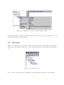
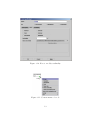
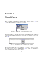
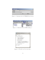
1
Introduction to the UML-Editor
Claude Eisenhut
V2.0.0 (February 13, 2004)
Contents
List of Figures
iv
1 Introduction
2
2 How To Start the UML-Editor
3
2.1
2.2
Windows . . . . . . . . . . . . . . . . . . . . . . . . . . . . . . . . . . . . .
3
2.1.1
System Configuration . . . . . . . . . . . . . . . . . . . . . . . . . .
3
2.1.2
Installation . . . . . . . . . . . . . . . . . . . . . . . . . . . . . . .
4
Mac . . . . . . . . . . . . . . . . . . . . . . . . . . . . . . . . . . . . . . .
4
2.2.1
System Requirements . . . . . . . . . . . . . . . . . . . . . . . . . .
4
2.2.2
Installation . . . . . . . . . . . . . . . . . . . . . . . . . . . . . . .
5
3 Data Modelling
6
3.1
Model and Class . . . . . . . . . . . . . . . . . . . . . . . . . . . . . . . .
6
3.2
Rename . . . . . . . . . . . . . . . . . . . . . . . . . . . . . . . . . . . . .
9
3.3
Deleting . . . . . . . . . . . . . . . . . . . . . . . . . . . . . . . . . . . . .
10
3.4
Attribute . . . . . . . . . . . . . . . . . . . . . . . . . . . . . . . . . . . .
10
3.5
Relationship . . . . . . . . . . . . . . . . . . . . . . . . . . . . . . . . . . .
10
3.6
Domaine, Unity . . . . . . . . . . . . . . . . . . . . . . . . . . . . . . . . .
12
3.7
Determining Order of Classes, Domaines and Units . . . . . . . . . . . . .
12
4 Creating a Documentation
17
5 Model Check
19
ii
6 From UML to INTERLIS
20
7 Graphic representation of INTERLIS
23
Bibliography
25
iii
List of Figures
2.1
The UML-Editor. . . . . . . . . . . . . . . . . . . . . . . . . . . . . . . . .
3
2.2
Establishing a link on your windows desk-top. . . . . . . . . . . . . . . . .
4
3.1
Main window of the UML-Editor. . . . . . . . . . . . . . . . . . . . . . . .
7
3.2
Menu item File/New. . . . . . . . . . . . . . . . . . . . . . . . . . . . . . .
8
3.3
Basic structure after selecting menu item File/New. . . . . . . . . . . . . .
8
3.4
Function New/Class in the navigation pane. . . . . . . . . . . . . . . . . .
9
3.5
The class Street. . . . . . . . . . . . . . . . . . . . . . . . . . . . . . . . . .
9
3.6
Function New/Attribute in the Navigation Pane. . . . . . . . . . . . . . . .
10
3.7
Specification dialog for an attribute. . . . . . . . . . . . . . . . . . . . . . .
11
3.8
A relationship between two classes. . . . . . . . . . . . . . . . . . . . . . .
12
3.9
Specification dialog for a role. . . . . . . . . . . . . . . . . . . . . . . . . .
13
3.10 How to modify cardinality. . . . . . . . . . . . . . . . . . . . . . . . . . . .
14
3.11 Context menu of a role. . . . . . . . . . . . . . . . . . . . . . . . . . . . . .
14
3.12 Function New/Unity on the navigation pane. . . . . . . . . . . . . . . . . .
15
3.13 Specification dialog for a unit. . . . . . . . . . . . . . . . . . . . . . . . . .
15
3.14 Defining dependency for a unit. . . . . . . . . . . . . . . . . . . . . . . . .
16
4.1
Menu item Reports/Object catalog.... . . . . . . . . . . . . . . . . . . . . .
17
4.2
Object catalog in the Web-Browser. . . . . . . . . . . . . . . . . . . . . . .
18
5.1
Menu item Tools/INTERLIS/Model check. . . . . . . . . . . . . . . . . . .
19
5.2
Error messages in the log pane after model check. . . . . . . . . . . . . . .
19
6.1
Specification dialog for an INTERLIS 2 file. . . . . . . . . . . . . . . . . .
20
iv
6.2
Dateiname für die INTERLIS-Datei ändern. . . . . . . . . . . . . . . . . .
21
6.3
Menu item Tools/INTERLIS/Export.... . . . . . . . . . . . . . . . . . . . .
21
6.4
The file bsp.ili in a text editor. . . . . . . . . . . . . . . . . . . . . . . . . .
21
6.5
Log pane after export of an INTERLIS-model file. . . . . . . . . . . . . . .
22
7.1
Function Tools/INTERLIS/Import.... . . . . . . . . . . . . . . . . . . . . .
23
7.2
Log pane after import of a INTERLIS-model file. . . . . . . . . . . . . . .
23
1
Chapter 1
Introduction
This introduction gives a step by step description of the UML-Editor . It is an aim of the
UML-Editor to enhance the use of the model-based method, to facilitate the mastering
of the complex subject of UML and INTERLIS thanks to an intuitive device and thus to
make it accessible to a greater number of users.
We presume understanding of UML and a certain knowledge of INTERLIS.
This introduction is not a reference manual.
You will find further information
• concerning the UML-Editor in the reference manual [8]
• concerning INTERLIS in the manuals [5], [6]
• concerning UML in various books z.B. [3], [4]
This manual is structured as follows
• chapter 2 explains how to start the editor,
• chapter 3 deals with data modeling,
• chapter 5 deals with the formal examination of the model,
• the conversion of UML in INTERLIS is explained in chapter 6,
• chapter 7 will teach you how to make a graphic representation of an existing INTERLIS model file.
2
Chapter 2
How To Start the UML-Editor
Depending on the configuration, a double-click on the file umleditor.jar is all that is
needed , to start the editor (fig. 2.1). If this should fail: consult chapter 2.1 for Windows
or chapter 2.2 for Mac.
Figure 2.1: The UML-Editor.
Depending on the configuration of your system, the texts (menu description, dialog title,
...) will be either in German or French.
2.1
2.1.1
Windows
System Configuration
In order to execute the UML-Editor, the JAVA-run time environment (JRE) version 1.4.2 or
more recent must be installed on your system. A free version of JAVA run time environment
(JRE) is available at the website http://www.java.com/.
3
2.1.2
Installation
In order to install the UML-editor, extract the ZIP-file into a new directory.
Establish a new link (fig. 2.2)on your desk-top. Als Location of object enter the following
command line:
javaw -jar "$UMLEDITOR\umleditor.jar"
$UMLEDITOR is a fill-in and corresponds to the UML-editor installation directory on
your system.
Figure 2.2: Establishing a link on your windows desk-top.
2.2
2.2.1
Mac
System Requirements
In order to execute the UML-editor, the JAVA-run time environment (JRE) version 1.4.2 or
more recent must be installed on your system. A free version of JAVA-run time environment
(JRE) is available at the website http://www.java.com/
2.2.2
Installation
In order to install the UML-Editor, extract the ZIP-file into a new directory.
4
Chapter 3
Data Modelling
In the following a detail of the data model Roads (from the INTERLIS-reference manual,
appendix C) will be modeled.
Having started the UML-Editor, the main window will appear (Fig. 3.1).
• The navigation pane on the left side of the main window of the UML-editor will guide
you as fast as possible to a certain element of the model.
• Within the modeling space data can be modeled graphically in individual diagrams.
• Within the documentation space a description concerning the currently selected
model element can be entered.
For further information see reference manual ([8], chapter 3).
3.1
Model and Class
Create a new data model using the menu item File/New ([8], chapter 3.1.1) (fig. 3.2).
A basic structure will be generated (fig. 3.3).
Add a new class (ClassDef) to this new model: In the navigation pane ([8], chapter 3.3)
mark the element ModelDef, press the right mouse button and use the function New/Class
(fig. 3.4).
Using the tool
a new class can be generated directly within a diagram. This tool is to
be found in the tool bar ([8], chapter 3.4.1).
Classes that have been generated in the navigation pane, will not be added automatically
to the diagram. In order to add this class to the diagram, mark the relevant class and
5
Figure 3.1: Main window of the UML-Editor.
6
Figure 3.2: Menu item File/New.
Figure 3.3: Basic structure after selecting menu item File/New.
7
Figure 3.4: Function New/Class in the navigation pane.
press the right mouse button. Using the function Insert in diagram ([8], chapter 3.3) you
can add the classes to the diagram.
3.2
Rename
All model elements can be modified: Mark an element and press the right mouse button.
By means of the function Rename you can assign new names to individual elements (Fig.
3.5).
Figure 3.5: The class Street.
Now you have both generated a small model and modified the names of the elements.
8
3.3
Deleting
Please note the difference between Deleting within a model and Deleting within a diagram:
When marking a class in a diagram and pressing the key Delete, the class will be deleted
in the diagram, but remains in the model (as you can easily see on the navigation pane).
In order to delete a class from the model you must press the right mouse button and use
the function Delete (within the model).
3.4
Attribute
On the navigation pane mark the class BoFlaechen and select the function New/Attribute
(Fig. 3.6) in the context menu (right mouse button).
Figure 3.6: Function New/Attribute in the Navigation Pane.
Assign the name Type to the attribute. For this, open the specification catalog of the
attribute: Mark the new attribute on the navigation pane and the select the function
M̈odify... in the context menu (Fig. 3.7).
3.5
Relationship
Generate one more class Gebaeude.
Using the tool
([8], chapter 3.4.1) generate a relation between the two classes BoFlaechen
and Gebaeude, by clicking the class BoFlaechen and pulling the mouse cursor (keep on
pressing the left mouse button) over to the class Gebaeude (release the left mouse button).
9
Figure 3.7: Specification dialog for an attribute.
10
You have now generated a relationship between the two classes (Fig. 3.8). Assign any
name to the relation (in our example GebaeudeFlaeche).
Figure 3.8: A relationship between two classes.
In the specification dialog ([8], chapter 4.2.11) of the two roles (Fig. 3.9) you can modify
your names. For one of the roles enter the name Flaeche and for the other the name
Gebaeude .
In the corresponding roles it is also possible to modify the cardinality (Fig. 3.10). Select
the value 1 for the role Flaeche and the value 0..* for the role Gebaeude.
By positioning the mouse cursor above a role (end of the relationship), the relationship
can be converted into a composition by means of the context menu (Fig. 3.11).
In order to define further properties of the relationship, you can mark the relationship and
open the specification dialog ([8], chapter 4.2.9).
3.6
Domaine, Unity
In order to define a domaine or a unity, mark the package in which you want to establish the
definition on the navigation pane. By means of the function New/Unity (in the context
menu) you then generate the corresponding definition (Fig. 3.12). Both domaines and
unities cannot be represented in a diagram in the UML-editor.
Modify the names of the unity in m. The exact definition of the unit will ensue by means
of INTERLIS. It is possible to enter a corresponding text in the INTERLIS syntax in the
specification dialog ([8], chapter 4.2.14) of the unity (Fig. 3.13).
3.7
Determining Order of Classes, Domaines and Units
Depending on the order in which model elements are entered in the UML-editor, they
will appear in a false order in the INTERLIS model file. In order to enforce a certain
11
Figure 3.9: Specification dialog for a role.
12
Figure 3.10: How to modify cardinality.
Figure 3.11: Context menu of a role.
13
Figure 3.12: Function New/Unity on the navigation pane.
Figure 3.13: Specification dialog for a unit.
14
order, a dependency relationship must be defined between the relevant model elements.
Such a dependency is defined by means of the tool
. However since e.g. units cannot
be represented in the diagram, the dependency can be indicated in the corresponding
specification catalog under Definition-Depends on (Fig. 3.14).
Figure 3.14: Defining dependency for a unit.
The dependency relationship between individual classes can be represented in the diagram.
15
Chapter 4
Creating a Documentation
When selecting a menu item Reports/Object catalog... ([8], chapter 3.1.6) (Fig. 4.1), you
must select a data name and thus an HTML-file will be generated.
Figure 4.1: Menu item Reports/Object catalog....
In this file all model elements will be listed along with their description. Using your
web-browser you can inspect and print this file (Fig. 4.2).
16
Figure 4.2: Object catalog in the Web-Browser.
17
Chapter 5
Model Check
When selecting the menu item Tools/INTERLIS/Model check ([8], chapter 3.1.7) (Fig.
5.1), the entire UML-model is checked for its correctness.
Figure 5.1: Menu item Tools/INTERLIS/Model check.
In a temporary directory the UML-editor generates all INTERLIS-files and checks them
by means of the INTERLIS-compiler. If any errors occur, they will appear in the log pane
(Fig. 5.2).
Figure 5.2: Error messages in the log pane after model check.
By positioning the mouse cursor on an error message, it is possible to open the corresponding specification catalog in the context menu (Fig. 5.2) by means of the function Select
nodes and thus the source oferror can be eliminated.
18
Chapter 6
From UML to INTERLIS
The name of the INTERLIS file, that is being generated, will be determined in the INTERLIS 2-file-specification dialog ([8], chapter 4.2.3) (Fig. 6.1).
Figure 6.1: Specification dialog for an INTERLIS 2 file.
Any name can be entered as file name (Fig. 6.2). Use your right mouse button to reach
M̈odify....
Using the button on the right side, right next to the text field, you can select a path as file
name. If the file name does not contain a path indication, then the INTERLIS-file will be
generated in the directory of the UML model file. You may generate (model) any number
of INTERLIS-files in a UML-model.
By selecting the menu item Tools/INTERLIS/Export... ([8], chapter 3.1.7) (Fig. 6.3), all
INTERLIS-model files will be generated (Fig. 6.4).
19
Figure 6.2: Dateiname für die INTERLIS-Datei ändern.
Figure 6.3: Menu item Tools/INTERLIS/Export....
Figure 6.4: The file bsp.ili in a text editor.
20
A message in the log pane will inform you whether the files have been successfully exported
or not (Fig. 6.5).
Figure 6.5: Log pane after export of an INTERLIS-model file.
21
Chapter 7
Graphic representation of INTERLIS
If you have already modeled by means of INTERLIS data, you can create a graphic representation of the existing INTERLIS-model file by using the UML-Editor. In order to convert
the INTERLIS-Model file into a UML-model, use the function Tools/INTERLIS/Import...
(Fig. 7.1). You will perceive a file selection dialog, where you can select the INTERLISmodel file (*.ili) that has to be converted.
Figure 7.1: Function Tools/INTERLIS/Import....
If errors occur during the conversion, e.g. if the INTERLIS-model file should contain a
syntactic error or if the INTERLIS-file cannot be found, these errors will appear in the log
pane of the UML-editor (Fig. 7.2).
Figure 7.2: Log pane after import of a INTERLIS-model file.
After a conversion the data model can be further treated with the usual application tools.
The navigation pane on the left side of the main window of the UML-editor will let you
attain a certain element of the model as fast as possible.
22
In order to view further properties of an element, e.g. parameters or its description, the
element must be marked and the dialog for specification must be opened via the contextmenu (right mouse button). Thereafter properties of the element, such as its description,
can be dealt with in the specification dialog (Fig. 3.7).
During conversion a diagram is automatically generated for each INTERLIS-topic; this
diagram will contain all classes of the topic. In general such automatically generated diagrams need further treatment, because the software cannot recognize the importance of a
class. When dealing with a topic with many classes, always generate several diagrams and
represent only one important class and its direct neighboring classes per diagram. In order
to have more free space in a survey diagram, you can suppress representation of attributes
for classes ([8], chapter 4.1.2).
23
Bibliography
[1] OMG, Object Management Group, http: // www. omg. org , The Object Management
Group (OMG) is an open membership, non-for-profit consortium that produces and
maintains computer industry specifications for interoperable enterprise applications.
Our membership includes virtually every large company in the computer industry, and
hundreds of smaller ones. Most of the companies that shape enterprise and Internet
computing today are represented on our Board of Directors.
[2] UML, Cetus-Links, http: // www. cetus-links. org , Various links to Objects &
Components
[3] Martin Fowler & Kendall Scott, UML konzentriert, Addison-Wesley
[4] James Martin & James Odell, Object-oriented methods a foundation, Prentice-Hall
[5] KOGIS, INTERLIS-Reference Manual, http: // www. interlis. ch
[6] KOGIS, INTERLIS-User Manual, http: // www. interlis. ch
[7] KOGIS, Introduction to the UML-Editor, http: // www. umleditor. org
[8] KOGIS, UML-Editor, http: // www. umleditor. org
24