1
VDAS Setup and Operating Instructions
__________________________________
21
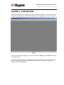
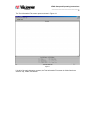
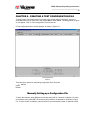
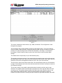
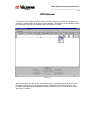
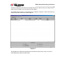
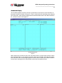
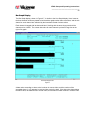
Channel Setup Screen
Figure 5.1
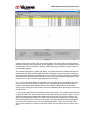
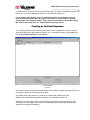
The screen is divided into three sections; top, middle, and bottom. This configuration is used
throughout the program.
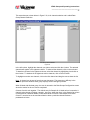
The top section of this screen identifies columns for each channel entry. The entry includes a
name, a symbolic channel number, its physical channel number, the type of channel, its range, its
precision, an optional scaling formula, a DSP filter bandwidth, a volt range, a volt threshold
percentage, an input frequency range, a pulse count reset interval, and two optional alarm
settings.
The middle section accepts entry of up to 300 channels (rows).
The legends in the bottom section of the screen define the operations that can be performed and
their associated function keys. Here you will find operations to add, delete, insert, import, and sort
channels, as well as file management functions to open, save, print, and close files.
The first column, which is the channel name field, can accommodate a name up to 50 characters
in length. The characters scroll to the left as data is entered into the field, if the name is more than
25 characters in length.
The next two columns, the symbolic and physical channel numbers, provide a way to map
channels. The symbolic channel number (Sym Ch#) allows the user to tag that channel in some
convenient way. The physical channel number (Phy Ch#) is the actual channel location on the
main chassis that provides the data. These two numbers permit the changing of physical
transducer connections without re-sorting through the data list to generate equivalent output data