1
F2-08DA--2
8-Ch. Voltage Output
11--4
F2-08DA-2 8-Channel Analog Voltage Output
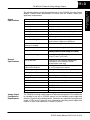
Special Placement
Requirements
(DL230 and
Remote I/O Bases)
Even though the module can be placed in any slot, it is important to examine the
configuration. As you can see in the section on writing the program, you use
V-memory locations to extract the analog data. If you place the module so the
output points do not start on a V-memory boundary, the instructions cannot access
the data. This also applies when module is placed in remote base (D2--RSSS in
CPU slot).
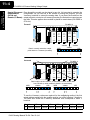
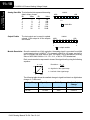
F2-08DA--2
Correct!
Slot 0
Slot 1
Slot 2
Slot 3
Slot 4
16pt
Input
8pt
Input
16pt
Output
16pt
Output
8pt
Output
X0
-X17
X20
-X27
Y0
-Y17
Y20
-Y37
V40500
V40502
V40501
MSB
LSB
Data is correctly entered so output
points start on a V-memory boundary.
Y
3
7
Y
2
0
Incorrect
F2-08DA--2
Slot 0
MSB
Slot 1
Slot 2
Slot 3
Slot 4
16pt
Input
8pt
Input
16pt
Output
8pt
Output
16pt
Output
X0
-X17
X20
-X27
Y0
-Y17
Y20
-Y27
Y30
-Y47
Data is split over two locations, so instructions cannot access data
from a DL230 (or when module is placed in a remote base).
V40502
V40501
LSB
MSB
LSB
Y Y
5 4
0 7
Y
5
7
Y40
-Y47
Y
4
0
Y Y
3 2
0 7
Y
3
7
Y
2
0
To use the V-memory references required for the multiplexing method, the first
output address assigned to the module must be one of the following Y locations.
The table also shows the V-memory addresses that correspond to these Y
locations.
Y
Y0
Y20
V
V40500 V40501 V40502 V40503 V40504 V40505 V40506 V40507
DL205 Analog Manual 7th Ed. Rev. B 4/10
Y40
Y60
Y100
Y120
Y140
Y160