1
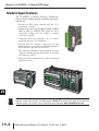
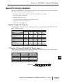
F0-04RTD 4-CHANNEL
RTD INPUT
CHAPTER
14
In This Chapter...
Module Specifications . . . . . . . . . . . . . . . . . . . . . . . . . . . . . . . . . . . . . . . . . . . . . . .14–2
Connecting and Disconnecting the Field Wiring . . . . . . . . . . . . . . . . . . . . . . . . . .14–4
Module Operation . . . . . . . . . . . . . . . . . . . . . . . . . . . . . . . . . . . . . . . . . . . . . . . . . .14–6
Special V-memory Locations . . . . . . . . . . . . . . . . . . . . . . . . . . . . . . . . . . . . . . . . . .14–7
Configuring the Module in Your Control Program . . . . . . . . . . . . . . . . . . . . . . .14–11
Negative Temperature Readings with Magnitude Plus Sign . . . . . . . . . . . . . . . .14–15
Analog Input Ladder Logic Filter . . . . . . . . . . . . . . . . . . . . . . . . . . . . . . . . . . . . .14–18
RTD Burnout Detection Bits . . . . . . . . . . . . . . . . . . . . . . . . . . . . . . . . . . . . . . . . .14–20
Chapter 14: F0-04RTD 4-Channel RTD Input
1
2
3
4
5
6
7
8
9
10
11
12
13
14
A
B
C
D
Module Specifications
14–2
The F0-04RTD 4-Channel Resistive Temperature
Detector Input Module provides the following features
and benefits:
• Provides four RTD input channels with 0.1 °C/°F
temperature resolution.
• Automatically converts type Pt100, jPt100, Pt1000,
10 Cu, 25 Cu, 120 Ni RTD signals into direct
temperature readings. No extra scaling or complex
conversion is required.
• Temperature data can be expressed in °F or °C, and as
magnitude plus sign or 2’s complement.
• Precision lead wire resistance compensation by dual
matched current sources and ratiometric measurements.
Works with three wire and four wire RTDs.
• The temperature calculation and linearization are based
on data provided by the National Institute of Standards
and Technology (NIST).
• Diagnostic features include detection of short circuits and
input disconnection.
R
PW
N
RU
U
CP
TX1
1
RX
TX2
2
RX
NOTE: The DL05 CPU’s analog feature for this module requires DirectSOFT32 Version 3.0c (or later) and
firmware version 4.70 (or later). The DL06 requires DirectSOFT32 version V4.0, build 16 (or later) and
firmware version 1.50 (or later). See our website for more information: www.automationdirect.com.
DL05/06 Option Modules User Manual; 7th Ed., Rev. A, 08/11
Chapter 14: F0-04RTD 4-Channel RTD Input
Module Calibration
The module automatically re-calibrates every five seconds to remove any offset and gain errors.
The F0-04RTD module requires no user calibration. However, if your process requires
calibration, it is possible to correct the RTD tolerance using ladder logic. You can subtract or
add a constant to the actual reading for that particular RTD. The actual reading can also be
scaled to obtain the desired value using ladder logic.
Input Specifications
The following table provide the specifications for the F0-04RTD Input Module. Review these
specifications to make sure the module meets your application requirements.
Input Specifications
Number of Channels
Input Ranges
4
Pt100:
PT1000:
jPt100:
10 Cu:
25 Cu:
120 Ni:
Resolution
Display Resolution
Absolute Maximum Ratings
Converter Type
Sampling Rate
Linearity Error (End to End)
PLC Update Rate
Temperature Drift
Maximum Inaccuracy
RTD Excitation Current
Common Mode Range
Notch Filter (Common Mode Rejection)
Digital Input Points Required
Power Budget Requirements
Operating Temperature
Storage Temperature
Relative Humidity
Environmental Air
Vibration
Shock
Noise Immunity
Replacement Terminal Block
Wire Size Range & Connector Screw Torque
16 bit (1 in 65535)
±0.1 °C, ±0.1 °F (±3276.7)
Fault Protected Inputs to ±50VDC
Charge Balancing, 24 bit
140ms per channel
±0.05 °C maximum, ±0.01 °C typical
4 channels/scan
15 ppm / °C maximum
±1 °C
200µA
0-5VDC
>50 db notches at 50/60Hz
None; uses special V-memory locations based on slot
70 mA @ 5VDC (supplied by base)
0 to 60° C (32 to 140° F)
-20 to 70° C (-4 to 158° F)
5 to 95% (non-condensing)
No corrosive gases permitted
MIL STD 810C 514.2
MIL STD 810C 516.2
NEMA ICS3-304
D0-ACC-4
28 - 16 AWG; 0.4Nm; DN-SS1 Screwdriver Recommended
-200.0 °C to 850.0 °C (-328 °F to 1562 °F)
-200.0 °C to 595.0 °C (-328 °F to 1103 °F)
-38.0 °C to 450.0 °C (-36 °F to 842 °F)
-200.0 °C to 260.0 °C (-328 °F to 500 °F)
-200.0 °C to 260.0 °C (-328 °F to 500 °F)
-80.0 °C to 260.0 °C (-112 °F to 500 °F)
DL05/06 Option Modules User Manual; 7th Ed., Rev. A, 08/11
1
2
3
4
5
6
7
8
9
10
11
12
13
14
A
B
C
D
14–3
Chapter 14: F0-04RTD 4-Channel RTD Input
1
2
3
4
5
6
7
8
9
10
11
12
13
14
A
B
C
D
Connecting and Disconnecting the Field Wiring
14–4
Wiring Guidelines
Your company may have guidelines for wiring and cable installation. If so, you should check
those before you begin the installation. Here are some general things to consider:
• Use the shortest wiring route whenever possible.
• Use shielded wiring and ground the shield at the transmitter source. Do not ground the shield at both
the module and the source.
• Unused channels require shorting wires (jumpers) installed from terminals CH+ to CH– to COM.
• Do not run the signal wiring next to large motors, high current switches, or transformers. This may
cause noise problems.
• Route the wiring through an approved cable housing to minimize the risk of accidental damage.
Check local and national codes to choose the correct method for your application.
To remove the terminal block, disconnect power to the PLC and the field devices. Pull the
terminal block firmly until the connector separates from the module.
You can remove the RTD module from the PLC by folding out the retaining tabs at the top and
bottom of the module. As the retaining tabs pivot upward and outward, the module’s connector
is lifted out of the PLC socket. Once the connector is free, you can lift the module out of its slot.
Use the following diagram to connect the field wiring. If necessary, the F0–04RTD terminal
block can be removed to make removal of the module possible without disturbing field wiring.
RTD - Resistance Temperature Detector
Use shielded RTDs whenever possible to minimize noise on the input signal. Ground the shield
wire at one end only, preferably at the RTD source.
Lead Configuration for RTD Sensors
The suggested three-lead configuration shown below provides one lead to the CH+ terminal,
one lead to the CH– terminal, and one lead to the common terminal. Compensation circuitry
nulls out the lead length for accurate temperature measurements.
Some sensors have four leads. When making connections, do not connect the second lead to the
CH+ input; leave that lead unconnected.
Do not use configurations that lack the use of the same color lead to both the CH– and COM
terminals. There is no compensation and temperature readings will be inaccurate.
This module has low RTD excitation current, worst-case dissipation with 100 RTDs
connected is only 0.016mW.
Wiring Connections For Typical RTD Sensor
Black
Black
To CH–
To COM
Sensor
Red
Red
(if applicable)
To CH+
No Connection
(if sensor has 4 leads, only
connect one lead to CH+)
DL05/06 Option Modules User Manual; 7th Ed. Rev. A, 08/11
Chapter 14: F0-04RTD 4-Channel RTD Input
Ambient Variations in Temperature
The F0-04RTD module has been designed to operate within the ambient temperature range of
0 °C to 60 °C.
Precision analog measurement with no long term temperature drift is assured by a chopper
stabilized programmable gain amplifier, ratiometric referencing, and automatic offset and gain
calibration.
Wiring Diagram
Use the following diagram to connect the field wiring. If necessary, the F0-04RTD terminal
block can be removed to make removal of the module possible without disturbing field wiring.
Note 1
Note 3
x
COM
COM
200 A
Current
Source
ANALOG MULTIPLEXER
Note 2
CH1+
CH1COM
CH2+
CH2COM
CH3+
CH3COM
CH4+
CH4-
RTD
COM
Ref.
Adj.
COM
+
- A/D
200 A
Current
Source
COM
COM
COM
F0-04RTD
Notes:
1. The three wires connecting the RTD to the module must be the same type and length.
Do not use the shield or drain wire for the third connection.
2. Unused channels require shorting wires (jumpers) installed from terminals CH+ to CH–
to COM to prevent possible noise from influencing active channels. This should be done
even if the unused channel is not enabled in the V-memory configuration.
3. If a RTD sensor has four wires, the plus sense wire should be left unconnected as shown.
DL05/06 Option Modules User Manual; 7th Ed. Rev. A, 08/11
1
2
3
4
5
6
7
8
9
10
11
12
13
14
A
B
C
D
14–5
Chapter 14: F0-04RTD 4-Channel RTD Input
1
2
3
4
5
6
7
8
9
10
11
12
13
14
A
B
C
D
Module Operation
14–6
Channel Scanning Sequence
The DL05 and DL06 read all four input channels data during each scan. The CPUs support
special V-memory locations that are used to manage the data transfer. This is discussed in more
detail on the following page, “Special V–memory Locations”.
Scan
DL05/DL06 PLC
Read Inputs
Execute Application Program
Read the data
Store data
Scan N
Ch 1, 2, 3, 4
Scan N+1
Ch 1, 2, 3, 4
Scan N+2
Ch 1, 2, 3, 4
Scan N+3
Ch 1, 2, 3, 4
Scan N+4
Ch 1, 2, 3, 4
Write to Outputs
Analog Module Update
Even though the channel updates to the CPU are synchronous with the CPU scan, the module
asynchronously monitors the analog transmitter signal and converts the signal to a 16-bit binary
representation. This enables the module to continuously provide accurate measurements
without slowing down the discrete control logic in the RLL program.
The time required to sense the temperature and copy the value to V-memory is 140 milliseconds
minimum to 560 milliseconds plus 1 scan time maximum (number of channels x 140
milliseconds + 1 scan time).
DL05/06 Option Modules User Manual; 7th Ed. Rev. A, 08/11
Chapter 14: F0-04RTD 4-Channel RTD Input
Special V-memory Locations
The DL05 and DL06 PLCs have special V-memory locations assigned to their respective option
slots. These V-memory locations allow you to:
• specify the number of input channels enabled and BCD/Binary data format
• specify the input pointer address
• specify the RTD input type
• specify the units code – temperature scale and data format
• specify burnout data value at burnout
• read module setup diagnostics
Module Configuration Registers
The table below shows the special V-memory locations used by the DL05 and DL06 PLCs for
the F0–04RTD module.
Module Configuration
Parameters
A: Number of Channels
Enabled / Data Format
B: Input Pointer
C: RTD Type
D: Units Code
E: RTD Burnout
Data Value
F: Diagnostic Error
DL05 and DL06 Option Slot
DL05
Slot
DL06
Slot 1
DL06
Slot 2
DL06
Slot 3
DL06
Slot 4
V7700
V700
V710
V720
V730
V7701
V7703
V7704
V701
V703
V704
V711
V713
V714
V721
V723
V724
V731
V733
V734
V7706
V706
V716
V726
V736
V7707
V707
V717
V727
V737
A: Number of Channels Enabled/Data Format Register
This V–memory location is used to define the number of input channels to be enabled and to
set the channel data to BCD or binary format.
Number of
Channel Data in Channel Data in
Channels Enabled BCD Format
Binary Format
1 Channel
2 Channels
3 Channels
4 Channels
K100
K200
K300
K400
K8100
K8200
K8300
K8400
MSB
LSB
Data Format
Number of channels
DL05/06 Option Modules User Manual; 7th Ed. Rev. A, 08/11
1
2
3
4
5
6
7
8
9
10
11
12
13
14
A
B
C
D
14–7
Chapter 14: F0-04RTD 4-Channel RTD Input
B: Input Pointer Register
1
2
3
4
5
6
7
8
9
10
11
12
13
14
A
B
C
D
14–8
This is a system parameter that points to a V-memory location used for storing module channel
input data. The V–memory location loaded in the input pointer V–memory location is an octal
number identifying the first V-memory location for the input data. This V–memory location is
user defined, but must use available consecutive V-memory locations. For example, loading
O2000 causes the pointer to write Ch 1’s data value to V2000/2001, Ch 2’s data value to
V2002/2003, CH 3’s data value to V2004/2005 and Ch 4’s data value to V2006/2007.
NOTE: Each channel’s data value occupies two (2) consecutive V-memory locations. This allows for more
than four (4) digits to be displayed if a BCD format for channel data is selected. For example: 1234.5 °F.
A binary format for either a 15-bit magnitude plus sign or 16-bit 2’s complement value will occupy the first
V-memory location of the two V-memory locations assigned for the slected channel.
Refer to the specific PLC’s user manual being used for available user V-memory locations.
C: RTD Type Selection Register
The F0-04RTD module supports six different RTD types. The type must be specified by
placing a value from the table shown below into a V-memory register. The register is
determined by the PLC type and slot number, as listed in the Module Configuration
Registers table on the previous page. For example, if using a Pt1000 RTD with a module
installed in slot 2 of a DL06, load a value of 4 into V713. All channels of the module must be
the same RTD type.
RTD
Type
Input
Selection
Pt100 (European curve w/TCR = .00385)
Cu10
Cu25
jPt100 (American curve w/TCR = .00392)
Pt1000
Ni120
K0
K1
K2
K3
K4
K5
The factory default setting is for Pt100 RTDs. This selects the DIN 43760 European
platinum type RTD. European curve type RTDs are calibrated to DIN 43760, BS1905, or
IEC751 specifications which is .00385 //°C (100 °C = 138.5).
The jPt100 type for the American curve 100 platinum RTD is more commonly used in
North America.
The Cu10 (10) and Cu25 (25) RTD settings are used with copper RTDs.
V-memory register
MSB
LSB
Input Type
Selection
DL05/06 Option Modules User Manual; 7th Ed. Rev. A, 08/11
Chapter 14: F0-04RTD 4-Channel RTD Input
D: Units Code Register
All RTD types are converted into a direct temperature reading in either Fahrenheit or Celsius.
The data contains one implied decimal place. For example, a value in V-memory of 1002
would be 100.2 °C or °F.
All RTD ranges can include negative temperatures, therefore the display resolution is from
–3276.7 to +3276.7.
Negative temperatures can be represented in either 2’s complement or magnitude plus sign
form. If the temperature is negative, the most significant bit in the V-memory location is set.
The 2’s complement data format may be required to correctly display bipolar data on some
operator interfaces. This data format could also be used to simplify averaging a bipolar signal.
To view this data format in DirectSoft32, select Signed Decimal.
The bipolar input ranges may be converted to a 15-bit magnitude plus sign or a 16-bit 2’s
complement value.
Bit 0 = Temperature Scale
0 = Temp in degrees F
1 = Temp in degrees C
Bit 1 = Data Format
0 = Magnitude plus sign bit format
1 = 2’s Complement format
Unit Code Register - Truth Table
Temperature Scale
Data Format
Bit 1
Bit 0
Value
°F
Magnitude + sign bit
0
0
K0
°C
Magnitude + sign bit
0
1
K1
°F
2’s Complement
1
0
K2
°C
2’s Complement
1
1
K3
Temp scale
MSB
LSB
Data Format
DL05/06 Option Modules User Manual; 7th Ed. Rev. A, 08/11
1
2
3
4
5
6
7
8
9
10
11
12
13
14
A
B
C
D
14–9
Chapter 14: F0-04RTD 4-Channel RTD Input
E: RTD Burnout Data Value Register
1
2
3
4
5
6
7
8
9
10
11
12
13
14
A
B
C
D
This register is used to define either up scale or down scale channel values when a channel RTD
burnout occurs.
Bit 0 = Up scale/down scale value at Burnout
0 = Up scale value at Burnout, 7FFFh (BCD/HEX) or 32767 (Binary)
written to CH register
1 = Down scale value at Burnout: 0000h (BCD/HEX) or 0 (Binary)
written to CH register
MSB
LSB
Up scale/down scale Burnout value
F: Diagnostics Error Register
14–10
This register is used to determine whether the configuration of the module is valid or not.
Bit 0 = Diagnostic bit:
0 = Module setup is valid
1 = Module setup is not valid
MSB
LSB
Diagnostics bit
DL05/06 Option Modules User Manual; 7th Ed. Rev. A, 08/11
Chapter 14: F0-04RTD 4-Channel RTD Input
Configuring the Module in Your Control Program
DL05 Example 1
The example program below shows how to setup the F0–04RTD for 4 input channels enabled,
use of a type Pt100 RTD on all 4 input channels, BCD channel data format, ºF temperature
scale, magnitude plus sign bit format, and with an up scale burnout value specified. Place this
rung anywhere in the ladder program or in the initial stage if you are using stage programming
instructions.
This is all that is required to read the temperature or voltage input data into V-memory
locations. Once the data is in V-memory you can perform mathematical calculations with the
data, compare the data against preset values, etc. V2000 is used in the example but you can use
any user V-memory location.
SP0
LD
K0400
-or -
LD
K8400
Loads a constant that specifies the number of input channels to scan
and the data format. The upper byte, most significant nibble (MSN)
selects the data format (0 = BCD, 8 = binary). The LSN selects the
number of channels (1, 2, 3 or 4).
The binary format is used for displaying data on some operator
interface units. K8400 enables 4 channels in binary format.
OUT
V7700
Special V-memory location assigned to the option slot that specifies
the data format and the number of channels to scan.
LDA
O2000
This loads an octal value for the first V-memory location that will be used
to store the incoming data. For example, the O2000 entered here using
the LDA instruction would designate the following addresses:
Ch1 – V2000/2001, Ch2 – V2002/2003, Ch3 – V2004/2005,
Ch4 – V2006/2007. See note on page 14-8.
OUT
V7701
The octal address (O2000) is stored here. Special V–memory location
V7701 is assigned to the option slot and acts as a pointer, which
means the CPU will use the octal value in this location to determine
exactly where to store the incoming data.
LD
K0
Loads a 0 into the accumulator to set the following parameters in
(V7703 – V7706).
OUT
V7703
Special V–memory location assigned to the option slot that specifies
the RTD Input Type. K0 selects a type Pt100 RTD.
See table on page 14-8 for selections.
OUT
V7704
Special V–memory location assigned to the option slot that specifies
the Units Code (temperature scale and data format) selections.
K0 selects a º F temperature scale and magnitude plus sign bit format.
See truth table on page 14-9 for selections.
OUT
V7706
Special V–memory location assigned to the option slot that specifies
the RTD up scale/down scale burnout value. K0 selects an up
scale burnout value of 7FFFh (BCD/HEX) or 32,767 (Binary). The value
is written to the channel input register when a RTD burnout occurs.
DL05/06 Option Modules User Manual; 7th Ed. Rev. A, 08/11
1
2
3
4
5
6
7
8
9
10
11
12
13
14
A
B
C
D
14–11
Chapter 14: F0-04RTD 4-Channel RTD Input
DL05 Example 2
1
2
3
4
5
6
7
8
9
10
11
12
13
14
A
B
C
D
14–12
The example program below shows how to setup the F0–04RTD for 2 input channels enabled,
use of a type Cu10 RTD on the first 2 input channels, BCD channel data format, ºC
temperature scale, 2’s complement format, and with a down scale burnout value specified.
Again, place this rung in the ladder program or in the initial stage if you are using stage
programming instructions.
SP0
LD
K0200
-or -
LD
K8200
Loads a constant that specifies the number of input channels to scan
and the data format. The upper byte, most significant nibble (MSN)
selects the data format (0 = BCD, 8 = binary). The LSN selects the
number of channels (1, 2, 3 or 4).
The binary format is used for displaying data on some operator
interface units. K8200 enables 2 channels in binary format.
OUT
V7700
Special V-memory location assigned to the option slot that specifies
the data format and the number of channels to scan.
LDA
O2000
This loads an octal value for the first V-memory location that will be used
to store the incoming data. For example, the O2000 entered here using
the LDA instruction would designate the following addresses:
Ch1 – V2000/2001, Ch2 – V2002/2003
See note on page 14-8.
OUT
V7701
The octal address (O2000) is stored here. Special V–memory location
V7701 is assigned to the option slot and acts as a pointer, which
means the CPU will use the octal value in this location to determine
exactly where to store the incoming data.
LD
K1
Loads a constant that specifies the RTD input type. K1 selects a type
Cu10 RTD. Enter a K0–K5 to specify the RTD Input Type.
See table on page 14-8 for selections.
OUT
V7703
Special V–memory location assigned to the option slot that specifies
the RTD input type.
LD
K3
Loads a constant that specifies the Units Code (temperature scale and
data format). K3 selects º C and 2’s complement data format.
See truth table on page 14-9 for selections.
OUT
V7704
Special V–memory location assigned to the option slot that specifies
the temperature scale and data format selections.
LD
K1
Loads a constant that specifies the RTD burnout data value at burnout.
K1 specifies a down scale value of 0000h (BCD/HEX) or 0 (Binary) to
be written to the channel input register when a RTD burnout occurs.
OUT
V7706
Special V–memory location assigned to the option slot that specifies
the RTD up scale/down scale burnout value. The value is written
to the channel input register when a RTD burnout occurs.
DL05/06 Option Modules User Manual; 7th Ed. Rev. A, 08/11
Chapter 14: F0-04RTD 4-Channel RTD Input
DL06 Example 1
The example program below shows how to setup the F0–04RTD in option slot 1 for 4 input
channels enabled, use of a type Pt100 RTD on all 4 input channels, BCD channel data format,
ºF temperature scale, magnitude plus sign bit format, and with an up scale burnout value
specified. Use the table shown on page 14–7 to determine the pointer values if locating the
module in any of the other slots. Place this rung anywhere in the ladder program or in the initial
stage if you are using stage programming instructions.
This is all that is required to read the temperature or voltage input data into V-memory
locations. Once the data is in V-memory you can perform mathematical calculations with the
data, compare the data against preset values, etc. V2000 is used in the example but you can use
any user V-memory location.
SP0
LD
K0400
-or -
LD
K8400
Loads a constant that specifies the number of input channels to scan
and the data format. The upper byte, most significant nibble (MSN)
selects the data format (0 = BCD, 8 = binary). The LSN selects the
number of channels (1, 2, 3 or 4).
The binary format is used for displaying data on some operator
interface units. K8400 enables 4 channels in binary format.
OUT
V700
Special V-memory location assigned to option slot 1 that specifies
the data format and the number of channels to scan.
LDA
O2000
This loads an octal value for the first V-memory location that will be used
to store the incoming data. For example, the O2000 entered here using
the LDA instruction would designate the following addresses:
Ch1 – V2000/2001, Ch2 – V2002/2003, Ch3 – V2004/2005,
Ch4 – V2006/2007. See note on page 14-8.
OUT
V701
The octal address (O2000) is stored here. Special V–memory location
V701 is assigned to option slot 1 and acts as a pointer, which means
the CPU will use the octal value in this location to determine exactly
where to store the incoming data.
LD
K0
Loads a 0 into the accumulator to set the following parameters in
(V703 – V706).
OUT
V703
Special V–memory location assigned to option slot 1 that specifies
the RTD Input Type. K0 selects a type Pt100 RTD.
See table on page 14-8 for selections.
OUT
V704
Special V–memory location assigned to option slot 1 that specifies
the Units Code (temperature scale and data format) selections.
K0 selects a º F temperature scale and magnitude plus sign bit format.
See truth table on page 14-9 for selections.
OUT
V706
Special V–memory location assigned to option slot 1 that specifies the
RTD up scale/down scale burnout value. K0 selects an up scale
burnout value of 7FFFh (BCD/HEX) or 32,767 (Binary). The value
is written to the channel input register when a RTD burnout occurs.
DL05/06 Option Modules User Manual; 7th Ed. Rev. A, 08/11
1
2
3
4
5
6
7
8
9
10
11
12
13
14
A
B
C
D
14–13
Chapter 14: F0-04RTD 4-Channel RTD Input
DL06 Example 2
1
2
3
4
5
6
7
8
9
10
11
12
13
14
A
B
C
D
14–14
The example program below shows how to setup the F0–04RTD in option slot 2 for 2 input
channels enabled, use of a type Cu10 RTD on the first 2 input channels, BCD channel data
format, ºC temperature scale, 2’s complement format, and with a down scale burnout value
specified. Use the table shown on page 14–7 to determine the pointer values if locating the
module in any of the other slots. V-memory location V3000 is shown in the example, but you
can use any available user V-memory location. Again, place this rung anywhere in the ladder
program or in the initial stage if you are using stage programming instructions.
SP0
LD
K0200
-or -
LD
K8200
Loads a constant that specifies the number of input channels to scan
and the data format. The upper byte, most significant nibble (MSN)
selects the data format (0 = BCD, 8 = binary). The LSN selects the
number of channels (1, 2, 3 or 4).
The binary format is used for displaying data on some operator
interface units. K8200 enables 2 channels in binary format.
OUT
V710
Special V-memory location assigned to option slot 2 that specifies
the data format and the number of channels to scan.
LDA
O3000
This loads an octal value for the first V-memory location that will be used
to store the incoming data. For example, the O3000 entered here using
the LDA instruction would designate the following addresses:
Ch1 – V3000/3001, Ch2 – V3002/3003
See note on page 14-8.
OUT
V711
The octal address (O3000) is stored here. Special V–memory location
V711 is assigned to option slot 2 and acts as a pointer, which
means the CPU will use the octal value in this location to determine
exactly where to store the incoming data.
LD
K1
Loads a constant that specifies the RTD input type. K1 selects a type
Cu10 RTD. Enter a K0–K5 to specify the RTD Input Type.
See table on page 14-8 for selections.
OUT
V713
Special V–memory location assigned to option slot 2 that specifies
the RTD input type.
LD
K3
Loads a constant that specifies the Units Code (temperature scale and
data format). K3 selects º C and 2’s complement data format.
See truth table on page 14-9 for selections.
OUT
V714
Special V–memory location assigned to option slot 2 that specifies
the temperature scale and data format selections.
LD
K1
Loads a constant that specifies the RTD burnout data value at burnout.
K1 specifies a down scale value of 0000h (BCD/HEX) or 0 (Binary) to
be written to the channel input register when a RTD burnout occurs.
OUT
V716
Special V–memory location assigned to option slot 2 that specifies
the RTD up scale/down scale burnout value. The value is written
to the channel input register when a RTD burnout occurs.
DL05/06 Option Modules User Manual; 7th Ed. Rev. A, 08/11
Chapter 14: F0-04RTD 4-Channel RTD Input
Negative Temperature Readings with Magnitude Plus Sign
With bipolar ranges, you need some additional logic to determine whether the value being
returned represents a positive temperature or a negative temperature. There is a simple solution:
• If you are using bipolar ranges and you get a value greater than or equal to 8000h, the value is
negative.
• If you get a value less than or equal to 7FFFh, the value is positive.
The sign bit is the most significant bit, which combines 8000h to the data value. If the value is
greater than or equal to 8000h, you only have to mask the most significant bit and the active
channel bits to determine the actual data value.
The following two programs show how you can accomplish this. The first example uses
magnitude plus sign (binary) and the second example uses magnitude plus sign (BCD).
Since you always want to know when a value is negative, these rungs should be placed before
any other operations that use the data, such as math instructions, scaling operations, and so
forth. Also, if you are using stage programming instructions, these rungs should be in a stage
that is always active. Note: you only need this logic for each channel that is using bipolar input
signals. The examples only show two channels.
Magnitude Plus Sign (Binary)
Check Channel 1
SP1
V2000
LD
V2000
Load channel 1 data from V-memory into the
accumulator. Contact SP1 is always on.
AND
K7FFF
This instruction masks the sign bit of the binary data, if
it is set. Without this step, negative values will not be
correct so do not forget to include it.
OUT
V2010
Put the actual signal value in V2010. Now you can use
the data normally.
K8000
Check Channel 2
SP1
V2002
K8000
C1
OUT
Channel 1 data is negative when C1 is on (a value of
–1.0 reads as 8010, –2.0 is 8020, etc.).
LD
V2002
Load channel 2 from V-memory into the accumulator.
Contact SP1 is always on.
AND
K7FFF
This instruction masks the sign bit of the binary data, if
it is set. Without this step, negative values will not be
correct so do not forget to include it.
OUT
V2012
Put the actual signal value in V2012. Now you can use
the data normally.
C2
OUT
Channel 2 data is negative when C2 is on (a value of
–1.0 reads as 8010, –2.0 is 8020, etc.).
DL05/06 Option Modules User Manual; 7th Ed. Rev. A, 08/11
1
2
3
4
5
6
7
8
9
10
11
12
13
14
A
B
C
D
14–15
Chapter 14: F0-04RTD 4-Channel RTD Input
Magnitude Plus Sign (BCD)
1
2
3
4
5
6
7
8
9
10
11
12
13
14
A
B
C
D
14–16
Check Channel 1
SP1
V2001
LDD
V2000
Load channel 1 data from V-memory into the
accumulator. Remember, the data can be negative.
Contact SP1 is always on.
ANDD
K7FFFFFFF
This instruction masks the sign bit of the BCD data, if it
is set. Without this step, negative values will not be
correct so do not forget to include it.
OUTD
V2010
Put the actual signal value in V2010. Now you can use
the data normally.
K8000
C1
OUT
Check Channel 2
SP1
V2003
K8000
Channel 1 data is negative when C1 is on (a value of
–1.0 reads as 8000 0010, –2.0 is 8000 0020, etc.).
LDD
V2002
Load channel 2 from V-memory into the accumulator.
Remember, the data can be negative. Contact SP1 is
always on.
ANDD
K7FFFFFFF
This instruction masks the sign bit of the BCD data, if it
is set. Without this step, negative values will not be
correct so do not forget to include it.
OUTD
V2012
Put the actual signal value in V2012. Now you can use
the data normally.
C2
OUT
Channel 2 data is negative when C2 is on (a value of
–1.0 reads as 8000 0010, –2.0 is 8000 0020, etc.).
DL05/06 Option Modules User Manual; 7th Ed. Rev. A, 08/11
Chapter 14: F0-04RTD 4-Channel RTD Input
Negative Temperatures 2’s Complement (Binary/Pointer Method)
You can use the 2’s complement mode for negative temperature display purposes, while at the
same time using the magnitude plus sign of the temperature in your control program. The
DirectSOFT32 element Signed Decimal is used to display negative numbers in 2’s complement
form. To find the absolute value of a negative number in 2’s complement, invert the number
and add 1 as shown in the following example:
V2000
K8000
LD
V2000
INV
Load negative value into the accumulator so we
can convert it to a positive value.
Invert the binary pattern in the accumulator.
ADDD
K1
Add 1.
OUT
V2010
Save Channel 1 data at V2010.
Repeat for other channels as required.
DL05/06 Option Modules User Manual; 7th Ed. Rev. A, 08/11
1
2
3
4
5
6
7
8
9
10
11
12
13
14
A
B
C
D
14–17
Chapter 14: F0-04RTD 4-Channel RTD Input
1
2
3
4
5
6
7
8
9
10
11
12
13
14
A
B
C
D
Analog Input Ladder Logic Filter
PID Loops / Filtering:
Please refer to the “PID Loop Operation” chapter in the DL06 or DL05 User Manual for
information on the built-in PV filter (DL05/06) and the ladder logic filter (DL06 only) shown
below. A filter must be used to smooth the analog input value when auto tuning PID loops to
prevent giving a false indication of loop characteristics.
Smoothing the Input Signal (DL06 only):
The filter logic can also be used in the same way to smooth the analog input signal to help
stabilize PID loop operation or to stabilize the analog input signal value for use with an operator
interface display, etc.
WARNING: The built-in and logic filters are not intended to smooth or filter noise generated by improper
field device wiring or grounding. Small amounts of electrical noise can cause the input signal to bounce
considerably. Proper field device wiring and grounding must be done before attempting to use the filters
to smooth the analog input signal.
Using Binary Data Format
14–18
SP1
LD
V2000
Loads the analog signal, which is in binary format
and has been loaded from V-memory location
V2000, into the accumulator. Contact SP1 is
always on.
BTOR
Converts the binary value in the accumulator
to a real number.
SUBR
V1400
Subtracts the real number stored in location
V1400 from the real number in the accumulator,
and stores the result in the accumulator. V1400
is the designated workspace in this example.
MULR
R0.2
Multiplies the real number in the accumulator by
0.2 (the filter factor), and stores the result in the
accumulator. This is the filtered value. The filter
range is 0.1 to 0.9. Smaller filter factors
increases filtering. (1.0 eliminates filtering).
ADDR
V1400
Adds the real number stored in
location V1400 to the real number
filtered value in the accumulator, and
stores the result in the accumulator.
OUTD
V1400
Copies the value in the accumulator to
location V1400.
RTOB
Converts the real number in the
accumulator to a binary value, and
stores the result in the accumulator.
OUT
V1402
Loads the binary number filtered value from
the accumulator into location V1402 to use in
your application or PID loop.
DL05/06 Option Modules User Manual; 7th Ed. Rev. A, 08/11
Chapter 14: F0-04RTD 4-Channel RTD Input
NOTE: Be careful not to do a multiple number conversion on a value. For example, if you are using the pointer
method in BCD format to get the analog value, it must be converted to binary (BIN) as shown below. If you
are using the pointer method in Binary format, the conversion to binary (BIN) instruction is not needed.
Using BCD Data Format
SP1
LDD
V2000
Loads the analog signal, which is in BCD format
and has been loaded from V-memory location
V2000, into the accumulator. Contact SP1 is
always on.
BIN
Converts a BCD value in the accumulator to
binary.
BTOR
Converts the binary value in the accumulator
to a real number.
SUBR
V1400
Subtracts the real number stored in location
V1400 from the real number in the accumulator,
and stores the result in the accumulator. V1400
is the designated workspace in this example.
MULR
R0.2
Multiplies the real number in the accumulator by
0.2 (the filter factor), and stores the result in the
accumulator. This is the filtered value. The filter
range is 0.1 to 0.9. Smaller filter factors
increases filtering. (1.0 eliminates filtering).
ADDR
V1400
Adds the real number stored in
location V1400 to the real number
filtered value in the accumulator, and
stores the result in the accumulator.
OUTD
V1400
Copies the value in the accumulator to
location V1400.
RTOB
Converts the real number in the
accumulator to a binary value, and
stores the result in the accumulator.
BCD
OUTD
V1402
Converts the binary value in the accumulator
to a BCD number. Note: The BCD instruction
is not needed for PID loop PV (loop PV is a
binary number).
Loads the BCD number filtered value from
the accumulator into location V1402 to use in
your application or PID loop.
DL05/06 Option Modules User Manual; 7th Ed. Rev. A, 08/11
1
2
3
4
5
6
7
8
9
10
11
12
13
14
A
B
C
D
14–19
Chapter 14: F0-04RTD 4-Channel RTD Input
1
2
3
4
5
6
7
8
9
10
11
12
13
14
A
B
C
D
RTD Burnout Detection Bits
Special Relays Corresponding to RTD Burnouts
14–20
The following Special Relay (SP) bits can be used in your program to monitor for RTD
burnout.
SP bit :
0 = RTD OK
1 = RTD burnout
DL05 and DL06 Option Slot
Module Channel
DL05
Slot
DL06
Slot 1
DL06
Slot 2
DL06
Slot 3
DL06
Slot 4
Channel 1
SP600
SP140
SP240
SP340
SP440
Channel 2
SP601
SP141
SP241
SP341
SP441
Channel 3
SP602
SP142
SP242
SP342
SP442
Channel 4
SP603
SP143
SP243
SP343
SP443
DL05/06 Option Modules User Manual; 7th Ed. Rev. A, 08/11