1
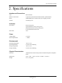
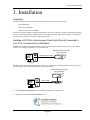
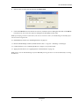
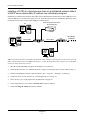
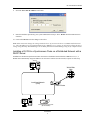
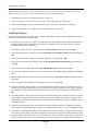
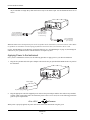
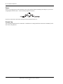
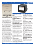
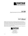
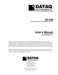
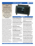
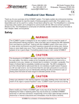
The way PC-based instrumentation should be
DI-789
Ethernet Repeater for Synchronous Ethernet Products
User'sManual
Manual
Revision A
Copyright © 2008 by DATAQ Instruments, Inc. The Information contained herein is the exclusive property of
DATAQ Instruments, Inc., except as otherwise indicated and shall not be reproduced, transmitted, transcribed, stored
in a retrieval system, or translated into any human or computer language, in any form or by any means, electronic,
mechanical, magnetic, optical, chemical, manual, or otherwise without expressed written authorization from the company. The distribution of this material outside the company may occur only as authorized by the company in writing.
DATAQ Instruments' hardware and software products are not designed to be used in the diagnosis and treatment of
humans, nor are they to be used as critical components in any life-support systems whose failure to perform can reasonably be expected to cause significant injury to humans.
DATAQ, the DATAQ logo, and WINDAQ are registered trademarks of DATAQ Instruments, Inc. All rights reserved.
241 Springside Dr.
Akron, Ohio 44333 U.S.A.
Telephone: 330-668-1444
Fax: 330-666-5434
Designed and manufactured in the
United States of America
Warranty and Service Policy
Product Warranty
DATAQ Instruments, Inc. warrants that this hardware will be free from defects in materials and workmanship under
normal use and service for a period of one year from the date of shipment. DATAQ Instruments' obligations under
this warranty shall not arise until the defective material is shipped freight prepaid to DATAQ Instruments. The only
responsibility of DATAQ Instruments under this warranty is to repair or replace, at its discretion and on a free of
charge basis, the defective material.
This warranty does not extend to products that have been repaired or altered by persons other than DATAQ Instruments employees, or products that have been subjected to misuse, neglect, improper installation, or accident.
DATAQ Instruments shall have no liability for incidental or consequential damages of any kind arising out of the sale,
installation, or use of its products.
Service Policy
1.
All products returned to DATAQ Instruments for service, regardless of warranty status, must be on a freight-prepaid basis.
2.
DATAQ Instruments will repair or replace any defective product within 5 days of its receipt.
3.
For in-warranty repairs, DATAQ Instruments will return repaired items to the buyer freight prepaid. Out of warranty repairs will be returned with freight prepaid and added to the service invoice.
DI–789 Hardware Manual
Table of Contents
Warranty and Service Policy ................................................................................................................
1. Introduction ........................................................................................................................................
Features ..............................................................................................................................................
Software .............................................................................................................................................
TCP/IP Manager .........................................................................................................................
Help .............................................................................................................................................
2. Specifications ......................................................................................................................................
3. Installation ..........................................................................................................................................
Unpacking ..........................................................................................................................................
Installing a DI-789 to a Synchronous Chain Directly Connected to your PC via a Hub/Switch ......
Installing a DI-789 to a Synchronous chain on network without a DHCP server .............................
Installing a DI-789 to a Synchronous Chain on a network with a DHCP Server ..............................
Installing Software .............................................................................................................................
Connecting the Device .......................................................................................................................
Applying Power to the Instrument .....................................................................................................
TCP/IP Manager ................................................................................................................................
4. Instrument Controls, Indicators, and Connectors ..........................................................................
DI-789 Front Panel ............................................................................................................................
Activity LEDs .............................................................................................................................
Sync Lost LED ............................................................................................................................
Power LED ..................................................................................................................................
DI-789 Rear Panel .............................................................................................................................
Toward PC and Expansion Ethernet Connections ......................................................................
Power ..........................................................................................................................................
Ground Lug .................................................................................................................................
Table of Contents
v
iii
1
1
1
1
1
3
5
5
5
8
9
10
11
12
13
15
15
15
15
15
15
15
16
16
DI-789 Hardware Manual
1. Introduction
Congratulations on your purchase of the DI-789 Repeater board. The DI-789 Repeater board is a specially designed
Ethernet switch that maintains synchonicity between DI-720/730/785/788 products that require distances greater than
100 meters apart.
Features
Features of model DI-789 include:
•
Compatability with all DATAQ Instruments Ethernet Synchronous devices (DI-720, DI-730, DI-785, DI788).
•
Expands distance between syncrhonous Ethernet devices by 100 meters.
•
12 VDC Power adapter included.
•
Activity LEDs for power, Ethernet activity, and indication of Lost Sync.
Software
All software required to setup DI-789 instruments is included with purchase.
TCP/IP Manager
The DATAQ Instruments TCP/IP Manager allows you to effectively manage and run multiple DI-72x/730/78x instruments installed or connected to your PC or your Network. This software can be found in the Start menu under the
WINDAQ program group called TCP/IP Manager. Access WINDAQ Acquisition software, configure auto-record settings, manage DATAQ networked devices, and more in this easy-to-use point and click environment. See xref for
more information.
Help
All WINDAQ software utilizes context-sensitive help. Help may be accessed through the Help menu or by pressing the
F1 key with any feature selected. This will take you directly to the Help topic most relevant to that particular function
or feature. Help topics discuss in detail each function available in the software.
Introduction
1
DI-789 Hardware Manual
2. Specifications
Interface and Connections
Type:
Ethernet (RJ45)
Interface Connections:
2 (upstream synchronization and downstream synchronization)
Power:
Standard DIN power connector (DC power supply provided)
Ground:
Ground lug screw
Indicators
Front Panel:
Power LED (green)
Upstream Ethernet activity LED (green)
Downstream Ethernet activity LED (green)
Lost Synchronization LED (red)
Rear Panel:
none
Power
Voltage Range:
9-36 VDC
Power Requirements:
< 5 Watts
Environmental
Operating Temperature:
-40°C to 70°C
Operating Humidity:
0 to 90% non-condensing
Storage Temperature:
-40°C to 70°C
Storage Humidity:
0 to 90% non-condensing
Physical Characteristics
Enclosure:
Aluminum base with steel wrap-around. Aluminum end-panels with plastic
bezels.
Dimensions:
5.4D × 4.1W × 1.5H in. (13.81D × 10.48W × 3.81H cm.)
Weight:
14 oz. (397 grams)
Specifications
3
DI-789 Hardware Manual
3. Installation
Unpacking
The following items are included with each instrument. Verify that you have the following:
•
DI-789 Instrument.
•
Power cable and adapter.
•
The WINDAQ Resource CD-ROM.
If an item is missing or damaged, call DATAQ Instruments at 330-668-1444. We will guide you through the appropriate steps for replacing missing or damaged items. Save the original packing material in the unlikely event that your
unit must, for any reason, be sent back to DATAQ Instruments.
Installing a DI-789 to a Synchronous Chain that is Directly Connected to
your PC or Connected via a Hub/Switch
Installation of an Ethernet Synchronous chain of devices directly connected to the network card on your computer
requires you to change the IP address of your network card.
Ethernet Synchronous Chain
(DI-72x/730/78x)
Standard CAT-5 Cable
100M Max
Your PC
Installation of an Ethernet Synchronous chain of devices via a hub/switch containing ONLY DI-72x/730/78x products also requires you to change the IP address of your network card.
Ethernet Synchronous Chain
(DI-72x/730/78x)
CAT-5 Cable
100M Max
Hub
Your PC
1.
Find the Network Connections on your computer (usually in the Control Panel).
2.
Double-click on the Local Area Connection icon.
Installation
5
DI-789 Hardware Manual
3.
Click on the Properties button.
4.
Select Internet Protocol (TCP/IP) in the “This connection uses the following items” window and click on the
Properties button.
5.
Click on the General tab.
6.
Select the radio button Use the following IP address.
7.
Enter 169.254.0.1 in the space provided for the IP address.
Installation
6
DI-789 Hardware Manual
8.
Enter 255.255.0.0 in the space provided for the Subnet mask.
9.
Click on the OK button to close the Internet Protocol (TCP/IP) Properties dialog box then click on the OK button in the Local Area Connection Properties dialog box for the changes to take effect.
Note: If you unplug your device and connect your PC to a network or router you should change the TCP/IP properties back to their original state.
10. Install WINDAQ software (see “Installing Software” on page 10).
11. Run the TCP/IP Manager software (default location is Start > Programs > WINDAQ > IP Manager).
12. Connect the device (see “Connecting the Device” on page 11) to your PC or hub.
13. Apply power the device (see “Applying Power to the Instrument” on page 12).
Note: Always start the TCP/IP Manager software BEFORE powering the device to avoid extended delays resolving
IP addresses.
Installation
7
DI-789 Hardware Manual
Installing a DI-789 to a Synchronous chain on a distributed network without
a DHCP server where static IP address are individually assigned
Installation of an Ethernet Synchronous chain connected to a distributed network that does not have a DHCP server or
where the DHCP server is turned off requires you to set a static IP to the device after installation to drastically reduce
the amount of time it takes for the TCP/IP Manager to find the device.
Ethernet Synchronous Chain
(DI-72x/730/78x)
PC
CAT-5 Cable
100M Max
Hub
CAT-5 Cable
100M Max
Hub
More Nodes
As Needed
Your PC
PC
Note: In the illustration above, the Ethernet Synchronous Chain could be located anywhere in the network. Also, the
Hubs could instead be routers with DHCP turned off (i.e., a static IP assigned network). Contact your system administrator for details about your network.
1.
Have the system administrator designate an IP address for your device(s).
2.
Install WINDAQ software (see “Installing Software” on page 10) entering the device’s MAC address at Step 13.
3.
Run the TCP/IP Manager software (default location is Start > Programs > WINDAQ > IP Manager).
4.
Connect the device to your network (see “Connecting the Device” on page 11).
5.
Power the device (see “Applying Power to the Instrument” on page 12).
6.
In the TCP/IP Manager main window, select the device you have installed.
7.
Select the Change IP Address drop down command.
Installation
8
DI-789 Hardware Manual
8.
Select the Set a static IP Address radio button.
9.
Enter the IP address provided by your system administrator in Step 1 above. Do not check the Remote Device
checkbox.
10. Click on the OK button for the change to take effect.
Note: These instructions change the settings inside the device. If you move the device to a DHCP-enabled network
(i.e., where IP addresses are assigned automatically by a DHCP server or router) you will need to change the device
settings using the Dataq TCP/IP Manager. See the Dataq Instruments TCP/IP Manager help file for complete details.
Installing a DI-789 to a Synchronous Chain on a Distributed Network with a
DHCP Server
Installation of an Ethernet Synchronous chain connected to a distributed network that has a DHCP server (i.e., a
DHCP router automatically assigns IP addresses to each device connected to the network) requires no extra setup.
Your PC
World Wide
Web
Local Area Network
(LAN)
DHCP Router
PC
Ethernet Synchronous Chain
(DI-72x/730/78x)
Installation
9
DI-789 Hardware Manual
Note: The Ethernet Synchronous Chain can be anywhere on the LAN. If you are unsure whether your network is
DHCP-enabled or not, check with your system administrator before installing WINDAQ.
1.
Install WINDAQ software (see “Installing Software” on page 10).
2.
Connect your device to your Local Area Network (see “Connecting the Device” on page 11).
3.
Run the TCP/IP Manager software (default location is Start > Programs > WINDAQ > IP Manager).
4.
Apply power to the device (see “Applying Power to the Instrument” on page 12).
Installing Software
Even though the DI-789 does not acquire data, you must install WINDAQ software and TCP/IP Manager software for
the device to work properly in the daisy chain.
1.
Insert the The WINDAQ Resource CD into your CD-ROM drive. The Windows auto run feature should start the
installation program. If the Windows auto run feature is not enabled on your PC, run the setup.exe program
located on the root of the CD directory.
2.
In the “What do you want to do?” dialog box select the Install Software radio button and click OK.
3.
In the “Installing Software” dialog box select the Install Software for all other products radio button and click
OK.
4.
In the “Specify the product” dialog box choose the WINDAQ/Lite option and click OK.
5.
In the “Specify the Instrument” dialog box select the DI-785/788/789 Desktop Instruments radio button and
click OK.
6.
In the “Select a Device” dialog box select the DI-785/788/789 ENB radio button and click OK.
7.
The “Welcome!” dialog box allows you to cancel the installation. Click OK to continue installation or Cancel to
abort.
8.
Read through the Software License agreement carefully and either Accept and Continue or Cancel to exit the
installation.
9.
Enter your Registration Information in the appropriate text boxes and click OK.
10. Select the destination directory where you would like all folders and files to reside on your hard drive. We recommend you accept the default path, but you can name this new directory anything you like. Simply substitute
the desired drive and directory in the Destination Directory text box. Once you have chosen the directory click
OK.
11. The “Make Backups?” dialog box provides the option of creating backup copies of any files that may be replaced
during installation. This is a safety courtesy; backup copies are not required. Click on No if you don't want to
make backups. Click on Yes to create backups. If you decide to create backups, you will be prompted to specify
a backup file directory.
12. Select the program manager group you would like to place the program shortcuts in your Windows programs.
The default is recommended, but you can specify any program group or create a new one. Click OK to continue.
13. You must know either the MAC address or the IP address of the device to continue. The MAC address is located
on the sticker on the bottom of your device. IP addresses must be retrieved from the system administrator. Enter
the MAC address or IP address in the text box provided in the “MAC or IP address of the device” dialog box. If
you are installing a device that is not connected to your Local Area Network, you should enter the IP address
Installation
10
DI-789 Hardware Manual
here. The software will go to that IP address and retrieve the MAC address for you. This will save further setup
in the TCP/IP Manager. Click OK to continue. Note: If you enter the wrong MAC address you will have to re-run
this installation program with the correct MAC address to access the device.
14. Click Yes in the “More ethernet devices to install” dialog box if you are installing multiple Ethernet devices.
15. Repeat Steps 12 and 13 until all Ethernet devices’ MAC addresses have been entered. Click No to continue
installation.
16. The “Installation Option” dialog box allows you to specify access to WINDAQ for multiple users on the same PC.
If you are the only user or you would like to allow access to all users click Yes. If there are multiple users and
you would like to be the only one able to access WINDAQ click No. Click Cancel to abort the installation.
17. Select the desired options for installation of WINDAQ/XL and Advanced CODAS.
18. Installation is complete. Run the TCP/IP Manager via the Windows program group specified during WINDAQ
Software installation (default is Start > Programs > WINDAQ > IP Manager) to access the device and run
WINDAQ Acquisition Software.
Connecting the Device
After power has been applied, install the DI-789 anywhere in a chain of Synchronous Ethernet instruments. Multiple
Ethernet products may be daisy-chained together to allow for one synchronous distributed data acquisition system.
Any combination of multiple DI-789s or Synchronous Ethernet instruments may be placed in the same daisy chain.
To maintain synchronicity, Ethernet hubs and switches cannot be used between units. Make sure to enter each MAC
address during installation. Daisy-chains must be installed to your Local Area Network (LAN) — you cannot access
more than one device per IP address outside of your subnet. If you are not sure whether or not the devices are in your
subnet see your system administrator before installation. You may acquire data from only one daisy chain at a time
(i.e., the same PC cannot access two daisy chained groups at the same time).
Note: If you are installing a daisy-chained group of instruments for the purpose of synchronous distributed data
acquisition, do not allow any other units or daisy chains to be installed to your subnet. Running other devices on the
same subnet will cause the synced units to become unsynced.
1.
Connect one end of a CAT-5 Ethernet cable to the Toward PC port of the first Ethernet device.
2.
Connect the other end of the same CAT-5 Ethernet cable to the Ethernet port on your PC or LAN.
3.
Connect one end of another CAT-5 Ethernet Cable to the Expansion port on the rear of the first Ethernet device.
4.
Connect the other end of the same CAT-5 Ethernet cable to the Toward PC port on the second Ethernet device.
5.
Continue installing more Ethernet devices by connecting a CAT-5 Ethernet cable to the Expansion port of the
last device in the chain and the Toward PC port on the next device you are adding to the chain. Up to 32 devices
Installation
11
DI-789 Hardware Manual
may be installed in a single daisy chain. Each device may be 100 meters apart. Use the illustration below for reference.
Connect to Expansion port
on previous DI-720/730 or to
the Ethernet port on your PC
or Network (up to 100 meters)
CAT-5 Ethernet Cables
(each cable can be up
to 100 meters long)
Connect to Toward PC
port on next DI-720/730
(up to 100 meters)
Note: DO NOT connect the Expansion port on the last product in the chain back to your network or PC. These Ethernet products use an Ethernet switch. Looping any Ethernet switch will cause your network or PC to crash.
Use the TCP/IP Manager to run WINDAQ Acquisition Software (see “TCP/IP Manager” on page 13) and manage IP
addresses in your synchronous chain. The DI-789 does not acquire any data.
Applying Power to the Instrument
Once you have installed the software, use the following procedure to apply power to your DI-789 instrument:
1.
Plug the five-pin DIN end of the power adapter cable into the five-pin jack labeled POWER on the rear panel of
the instrument.
Power Adapter Cable
Power Adapter
To power supply (outlet)
2.
Plug the appropriate end of the supplied power cord into the power adapter and the other end into any standard
120VAC, 60Hz, single-phase outlet. If an alternate power source is to be used, refer to the following pin-out diagram for power requirements:
+9 to +36 V
Common
When power is properly applied, the power LED on the front of the instrument will glow green.
Installation
12
DI-789 Hardware Manual
TCP/IP Manager
The TCP/IP Manager allows you to easily manage all DI-789, DI-720, DI-722, DI-730, DI-785, and DI-788 Ethernet
Instruments installed on your PC. The TCP/IP manager is installed when installing WINDAQ Software. Access the
TCP/IP Manager via the Windows program group specified during WINDAQ Software installation (default is Start >
Programs > WINDAQ > IP Manager). For help with TCP/IP settings and the TCP/IP Manager see the help files
accessible in the application (press F1 to access context-sensitive help or use the Help menu).
The main TCP/IP window shows all Ethernet devices installed on your PC. Devices could be busy or unavailable if
there are multiple users. If you entered the wrong MAC address during installation, the status of the device will be
“Off Line.” “UnSynced” devices are all single units installed to your network (units that are not daisy-chained).
Synced Groups are daisy-chained instruments. There is one Synced Group for each daisy chain. Each Synced Group
is named using the first device in the chain (in parentheses).
Use the drop down command menu to change the description of a device. All commands are performed by first
selecting a device, then using the drop down command menu. Multiple devices in the same Synced Group may be
selected for a recording session by using the Shift or Control key. Multiple Synced Groups cannot be accessed by the
same PC at the same time.
WINDAQ Acquisition software must be initiated from the TCP/IP Manager for all Synchronous Ethernet instruments.
To begin a recording session select a single device or a group of daisy-chained devices (using the Control or Shift
key) and click the Start WINDAQ button. Each device (except the DI-789) will open an instance of WINDAQ Acquisition software. Change channel settings, calibration, and display options independently for each device using each
instance of WINDAQ. Most WINDAQ menu items are available when recording synced devices with the following
exceptions: The Open and Record menu items in the File Menu are not available; The Triggered Mode, Triggered
Storage, and Remote Storage menu items in the Options Menu are not available.
Installation
13
DI–789 Hardware Manual
4. Instrument Controls,
Indicators, and Connectors
View LED indicators on the front panel of DI-789 instruments. Power, communications, and the ground lug can be
found on the rear of the instrument.
DI-789 Front Panel
Activity LEDs
These LEDs will glow green to show activity. The Ethernet Activity LEDs (Toward PC and Expansion) correspond
with the Ethernet ports on the rear of the instrument.
Sync Lost LED
This LED will glow red when the unit is inside a chain of Ethernet devices that are no longer acquiring data synchronously.
Power LED
This LED glows green when power is applied to the device.
DI-789 Rear Panel
Toward PC and Expansion Ethernet Connections
Two 10baseT ports. Connect the Toward PC port to an Ethernet port on your PC or Network. Use the Expansion
port to daisy-chain multiple units together.
Instrument Controls, Indicators, and Connectors
15
DI–789 Hardware Manual
Power
Allows you to apply power to the instrument. Power can be applied with the included power adapter or you can use
an appropriate alternate source - use the following diagram for pin out.
If power is on the Power LED on the front panel of the instrument will be on.
Ground Lug
This ground lug should always be connected to a solid chassis or earth ground. This connection is mandatory for the
unit to meet CE guidelines.
Instrument Controls, Indicators, and Connectors
16