1
MetraBus User’s Guide
Keithley Instruments, Inc.
28775 Aurora Road, Cleveland, OH 44139
Technical Support: I-888-KEITHLEY
Monday -Friday 8:00 a.m. to 5:OOp.m. (EST)
Fax: (440) 248-6168
httD://www.keithlev.com
Revision F - July, 1994
Pari Number: 62470
The information contained in this manual is believed to be accurate and reliable. However, Keithley
Instruments, Inc., assumes no responsibility for its use or for any infringements of patents or other
rights
of third parties that may result from ik use. No license is granted by implication or otherwise
under any patent righk
of Keithley Instruments, Inc.
KEITHLEY INSTRUMENTS, INC., SHALL NOT BE LIABLE FOR ANY SPECIAL,
INCIDENTAL, OR CONSEQUENTIAL DAMAGES RELATED TO THE USE OF THIS
PRODUCT. THIS PRODUCT IS NOT DESIGNED WITH COMPONENTS OF A LEVEL OF
RELIABILITY SUITABLE FOR USE IN LIFE SUPPORT OR CRITICAL APPLICATIONS.
Refer to your Keithley hWrumenk
warranty and liability information.
license agreement and Conditions of Sale document for specific
MetraByte is a trademark of Keithley hMru.menk, Lnc. AU other brand and product names are
&ademarks or registered trademarks of their respective companies.
@Copyright
Keithley
Instruments,
Inc. 1991,1992, 1993,1994
Au rights reserved. Reproduction or adaptation of any part of this doctunentation beyond that
permitted by Section 117 of the 1976 United States Copyright Act without pem&zion of the Copyright
owner is unlawful.
Keithley MetraByte Division
Keithley
Instruments,
Inc.
440 Myles Standish Blvd., Taunton, h4A02780
TEL 508/880-3000 * FAX 5081880-0179
Contents
CHAPTER 1 - INTRODUCTION
i::
:::
2
1:7
General Overview. ..................................
The MetraBus Cable ..................................
MetraBus Boards
Mounting & Connection.
............................
MetraBus Addressing .................................
Programming .....................................
Additional Notes ....................................
,1-l
l-l
1-2
: : : : : : : : : : : : : : : : : : : II-3
.I-4
.I-4
l-6
CHAPTER 2 - THE CONTROLLER BOARDS
Part 2A: MDB-64 Driver Board
2A.1
General . . . . . . . . . . . . . . .
Features
2A.2
Specificat’ions : : : : : : : : : : : :
2A.3
Setting The Base Address Switch .
2A.4
Installing The MDB-64 Fuse (Fi) .
2A.5
Installing The MDB-64 Driver Card
2A.6
The MDB-64 MetraBus Connector.
2A.7
2A.8
Programming The MDB-64. . . . .
Part 2B: MID-64 Driver Board
28.1
General . . . . . . . . . . . . . .
Features
2B.2
Specificat’ions : : : : : : : : : : :
28.3
Setting The Base Address Switch
Use 0-t The Auxiliary Supply . . .
z-i
Installing The Mid-64 Drier Card
2B:6
The MID-64 MetraBus Connector
2B.7
Programming The MID-64 . . . .
2B.8
. . . . . . . . . . . . . . . . . . . . . . . . : I??-;
: : : : : : : : : : : : : : : : : : : : : : : : . 2A-2
. . . . . . . . . . . . . . . . . . . . . . . . . 2A-2
. . . . . . . . . . . . . . . . . . . . . . . . . 2A-3
. 2A-3
: : : : : : : : : : : : : : : : : : : : : : : : . 2A-4
. . . . . . . . . . . . . . . . . . . . . . . . .2A-4
. . . . . . . . . . . . . . . . , . . . . . . . . .28-l
. 2B-2
: : : : : : : : : : : : : : : : : : : : : : : : : .2B-2
. . . . . _. . . . . .
. . 2B-2
. . . . . . . . . . . . : : : : : : : : : : : : . . .2B-3
. . . , . . . . . . . . . . . . . . . . . . . . . . 28-3
. . . , . . . . . . . . . . . . . , , . . . . . . . 2B-4
. . . . . . . . . . . . . . . . . . . . , . . . . . 2B-5
Part 2C: pCMDB-64 Driver Board
.2c-1
2c.1
General
Specifications 1 1 1 1 1 1 1 1 1 1 1 1 1 1 1 1 1 1 1 1 1 1 1 1 1 1 1 1 1 1 1 1 1 1 1 1 .2C-1
2c.2
Use Of An Auxiliary Power Supply. . . . . . . . . . . . . . . . . . . . . . . . . .2C-2
2C.3
System Configuration. . . . . . . . , . ; . . . . . . . . . . . . . . . . . . . . . .2C-2
2C.4
Programming . . . . . . . . . . . . . . . . . . . . . . . . . . . . . . , . . . . . .2C-7
2c.5
Part 2D: REhh-64 Driver Board
2D.I
General . . . . . . . . . . . . . . . . . . . . . . .
2D.2
Features. . . . . . . . . . . . . . . . . . . . . . .
g$;E;tions
. . . . . . . . . . . . . . . . . . . .
2D.3
2D.4
Connectors’ : : : : : : : : : : : : : : : : : : : : :
2D.5
Use of An Auxiliary Power Supply . . . . . . . . .
2D.6
Installation Of The REM-64. . . . . .
2D.7
Programming The REM-64 To Control ‘M’etraBus :
2D.8
.. .
- Ill -
. . . . . . . . . . . . . . . . .2D-1
. , . . . . . . . . . . . . . . .2D-2
. . . . . . . . . . . . . . . : : :X$-g
: : : : : : : : : : : : : : : . * 2D-5
. . . . . . . . . . . . . . . : : zLD-77
: : : : : : : : : : : : : : : . . 2D-8
Contents
CHAPTER 3 - THE POWER SUPPLY BOARDS
Part 3A: PWR-ZVPWR-100 Boards
3A.1
3A.2
Features
General, , . . . . . . . . . . . . . . . . . . . . . . . . . . . .
Specifications’ : : 1 1 1 1 1 1 1 1 1 1 1 1 1 1 1 1 1 1 1 1
3A.4
3A.3
Installing The PWR-55/PWR-100
111:
3A.5
Use of Other Power
. . . . . . . . . . . . . . . .
TheMTAP. . . . Supplies
. . . . . .. .. . . . . . . . . . . . . . . . .
3A.6
. . . . . . . . . . 3A-1
3A-1
1 1 1 1 1 1 1 1 1 1 3A-2
. . . . . . . . . . 3A-2
. . . . . . . . . . 3A-2
3A-3
Part 38: MBUS-PWR Boards
3B.1
General........................,.............:.
3B.2
Features
Specifications’
111 11111111111 1111111111 111111111 11
3B.3
1
Installation
.
3B.4
. Ground
. . . . .Jumper
.
: : : : : : : : : : : : : : : : : : : : : : : : : : :
Use of Output
3B.5
3B.6
The
MATP-1
The MBUS-PWk
‘cbnnkdtdrs : : : : : : : : : : : : : : : : : : : : : : : : : : : :
38.7
3B-1
38-2
3B-2
3B-3
3B-3
3B-3
3B-3
CHAPTER 4 - MDI-16/M%-16 SOLID STATE SWITCHING I/O SYSTEM
General, . . . . . . . . . . . . . . . . . . . . . . . . . . . . . . . . . , . . . . . . 4-1
Features
Specifications 1 1 1 1 1 1 1 1 1 1 1 1 1 1 1 1 1 1 1 1 1 1 1 1 1 1 1 1 1 1 1 1 1 1 1 1 1 ;::
Using An Auxiliary Supply . . . . . . . , . . . . . . . . . . . . . . . . . . . .
. 4-2
Configuring The MSS-16 . . . . . . . . . . . . . . . . . . . . . . . . . . . . : : . 4-2
Installing The MDI-16
CHAPTER 5 - THE RELAY BOARDS
Part 5A: MEM-8 Electromechanical Relay I/O System
5A.l
General. . . . . . . . . . . . . . . . . . .
5A.2
Specifications . . . . . . . . . , . . . . .
5A.3
Using An Auxiliary Power Supply
5A.4
Setting The MEM-8 Board Address : : : :
5A.5
Programming The MEM-8 . . . . . . . . .
5A.6
Use of Alternative Relays . . . . . . . . .
. . . . . . . . .
SA-1
. _. .
: ’ ’ ’ ’ * ’ . ’ ’ * * !iA-3
SA-3
: : : I- : : ’ * ’ . ’ . . ’ ’ ’ ’ ’ ’ * : 5A-3
. . . . . . : : : : : : : : : : : : : : . 5A-4
. . . . . . . . . . . . . . . . . . . . . 5A-5
_.
.
.
.
Part 58: MEM-32/A & MEM-32/W Electromechanical Relay System
58.1
General. . . . . . . . . . . . . . . . . . . . ....................
5B.2
Features
....................
5B.3
Specifications’ 1 1 1 1 1 1 1 1 1 1 1 1 1 1 1 1 ....................
5B.4
Using An Auxiliary Power Supply
....................
5B.5
Setting The MEM-32 Board Address : : : : ....................
5B.6
Typical Output Connections . . . . _ . . . . ....................
5B.7
Programming The MEM-32 . .
....................
5B.8
Using Compiled Or Assembled ian&&-% ’ ....................
- iv -
.
.
.
.
.
.
.
.
.
.
.
.
.
.
“I._
5B-1
58-2
5B-2
E-33
58-4
5B-4
5B-7
Contents
Part 5C: MSSR-32 Solid State Switching
5C.l
General . . . . . . . . . . .
5c.2
Features. . . . . . . . . . .
Specifications
E-i
Use Of An AuxkySuppiy:
5c:5
Configuring The MSSR-32 .
Installing The MSSR-32 . .
5C.6
I/O Module
. . . . . . . . . . . . . . . . . . . . . . . . . . . .
. . . . . . . . . . . . . . . . . . . . . . . . . . . .
.
: : : : : : : : : : : : : : : : : : : : : : : : : : : .
. . . , . . . . .
. . . . . . . . . : : : : : : : : : : : : : : : : : : :
. SC-1
. SC-2
. SC-2
.5C-2
5c-3
: 5C-3
Part 5D: MCPT-8X8 Cross-Point, Matrix Relay Board
5D.l
General
.
Specifications : -1 1 1 1 1 1 1 1 1 1 1 1 1 1 1 1 1 1 1 1 1 1 1 1 1 1 1 1 1 1 1 1 1 1 .
5D.2
5D.3
Use Of An Auxrlrary Power Supply. . . . . . . . . . . . . . . . . . . . . . . . .
5D.4
Jumpers And Switches . . . . . . . . . . . . . . . . . . . . . . . . . . . . . . .
Resistor Termination Networks. .
5D.5
Installing The MCPT-8X8. , . . . : : : : : : : : : : : : : : : : : : : : : : : : :
5D.6
5D.7
Programming The MCPT-8X8 . . . . . . . . . . . . . . . . . . . . . . . . . . .
.5D-1
.5D-2
.5D-3
.5D-3
5D-4
: 5D-4
.5D-4
CHAPTER 6 - THE LOGIC LEVEL l/O BOARDS
Part 6A: MIO-32 Isolated Digital Output Board
6A.l
General . . . . . . . . . . . . . . . . . . . . . . . . . . . . . . . . . . . . .
6A.2
Features
Specifications 1 1 1 1 1 1 1: 1 1 1 1 1 1 1 1 1 1 1 1 1 1 1 1 1 1 1 1 1 1 1 1 1:
6A.3
Using An Auxiliary Power Supply
6A.4
Installing The MIO-32. . . . . . . : : : : : : : : : : : : : : : : : : : : : : :
6A.5
Typical Output Connections
6A.6
Programming TheMIO-32 . : : : : : : : : : : : : : : : : : : : : : : : : : :
6A.7
Using Compiled Or Assembled Languages . . . . . . . . . . . . . . . . . .
6A.8
. . .6A-1
. 6A-2
1 1 . 6A-2
6A-3
: : : 6A-3
. 6A-4
: : . 6A-5
. . . 6A-7
Part 6B: MII-32 Isolated Digital Input Board
General ........................................
6B.1
6B-1
Features ............
6B.2
6B-2
Specifications .........
68.3
1 1 1 1 1 1 1 1: 1 1 1 1 1 1 1 1 1 1 1 1: 1 1 1 1 1 1 6B-2
Using An Auxiliary Power Supply
6B.4
6B-3
Installing The MI!-32 ... ....
6B.5
: : : : : : : : : : : : : : : : : : : : : : : : : : 68-3
Configuring The Mll-32 For Non-standard Inputs ..................
6B.6
654
Typical Input Connections
6B.7
6B-4
Programming The Mll-32. : : : : : : : : : : : : : : : : : : : : : : : : : : : : : : 6B-5
6B.8
Using Compiled Or Assembled Languages .....................
6B.9
6B-7
-V-
Contents
CHAPTER 7 - MCN-8 COUNTER/TIMER BOARD
;::
2
T-56
7:7
7.8
7.9
General. . . . . . . . . . . . . . . . . . .
Features
Specification’s* * : : : : : : : : : : : : : :
Use Of An Auxiliary Supply . . , . . . . .
Installing The MCN-8
Cascading The MCN-8’Coun’ters : : : : :
Typical Input Connections . . . . . . . . .
Programming The MCN-8 . . . . . . . . .
Using Compiled Or Assembled Languages
. . . . . . . . . . . . . . . . . . . . .
.
: : : : : : : : : : : : : : : : 1: : : .
. . . . . . . . . . . . . . . . . . . . .
: : : :
. . . .
. . . .
. . .
:
.
.
.
:
.
.
.
:
.
.
.
:
.
.
.
:
.
.
.
:
.
.
.
:
.
.
.
:
.
.
.
:
.
.
.
:
.
.
.
:
.
.
.
:
.
.
.
:
.
.
.
:
.
.
.
:
.
.
.
:
.
.
.
:
.
.
.
.
.
.
,
.
.
.
.
.
7-1
7-2
7-2
7-3
7-3
7-4
7-4
7-7
7-8
CHAPTER 8 - THE ANALOG I/O BOARDS
Part 8A: MAO-8 Analog Output Board
General. .......................................
8A.l
$A-1
Features
8A.2
. 8A-2
8A.3
Specificatiork’.~ : : : : : : : : : : : : : : : : : : : : : : : : : : : : 1 : : : : : . 8A-2
8A.4
Use Of An Auxrlrary Power Supply .......................
: : 883-z
Installing The MAO-8
8A.5
ProgrammingTheMAd-~::::::::::::::::::::::::::::
8A.6
. . 8A:6
Calibration And Adjustment Of The MAO-8
.;;;; ;
8A.7
......................
8A.8
Serviceable Parts .....
.. ..
......................
Part 88: MAO-12 Analog Output Board
8B.l
General. . . . . . . . . . . . . . .
8B.2
Features
8B.3
Specifications : : : 1 : : 1 : : : :
8B.4
Use Of An Auxiliary Power Supply
8B.5
Installing The MAO-1 2 , . . . . . .
8B.6
Programming The MAO-1 2 . . . .
. . . . . . . . . . . . . . . . . . . . . . . . .
.
: : : : : : : : : : : : : : : : : : : : : : : : .
. . . . . . . . . . . . . . . , . . . . . . , . .
. . . . , . . . . . . . . . , . . . . . . . . . .
. . . . . . . . . . . . . . . . . . . . . . . . .
Part 8C: MAI- Analog Input Board
8C.l
General. . . .
Features . . . : : : : : : : : : : : : : : : :
8C.2
Specifications . . . . . . . . . . . . . . . .
8C.3
8C.4
Using An Auxiliary Power Supply . . . . . .
Installing The MAI-I 6 . . . . . . . . . . . .
8C.5
8C.6
Typical Input Connections . . . . . . . s . ,
8C.7
Input Signal Attenuation . . . . . . . . . . .
Measuring Signals Greater Than +I 0 VDC .
8C.8
Measuring Signals Smaller Than +I .25 VDC
8C.9
Measuring Current With The MAI- 6 . . . .
E4 :
Auto Convert Mode Of Operation . . . . , .
A/D Resolution Via Hardware . . . , . . . .
8C:12
SC.13
Gain Selection Via Hardware . . . . . . . .
Programming The MAI- 6 . . . . . . . . . .
8C.14
Using Compiled Or Assembled Languages
Calibration Procedure For MAI. , . . .
3
- vi-
:
.
.
.
.
.
.
.
.
.
,
.
.
:
.
.
.
.
.
.
.
.
.
.
.
.
1:
. .
. .
. .
. .
. .
. .
. .
. .
. .
. .
. .
. .
:
.
.
.
.
.
.
.
.
.
.
.
.
:
.
.
.
.
.
.
.
.
.
.
.
.
:
.
.
.
.
,
.
.
.
.
.
.
.
:
.
.
.
.
.
.
.
.
.
,
.
.
:
.
.
.
.
.
.
.
.
.
.
.
.
:
.
.
.
.
.
.
.
.
.
.
.
.
:
.
.
.
.
.
.
.
.
:
.
.
.
:
.
.
.
.
.
.
.
.
.
.
.
.
:
.
.
.
:
.
.
.
:
.
.
.
:
.
.
.
:
.
.
.
.
.
.
.
:
.
.
.
.
.
.
.
:
.
.
.
.
.
.
.
:
.
.
.
.
.
.
.
: : : : : : : : : : : : : : : :
8B-1
8B-2
8B-2
88-3
8B-3
8B-5
8C-1
8C-2
8C-2
8C-3
8C-3
8C-4
: : : i 883-z
.
. : : . 8&
. . . . 8C-6
. . . . 8C-6
, . . . 8C-7
. . . . 8C-7
. . . , 8C-8
8C-12
: : : : 8C-13
:
.
.
.
:
.
.
.
:
.
.
.
:
.
.
.
Contents
Part 8D: MTHERM-20 Thermocouple Input Board
8D.l
General
. 8D-1
Functional bescnptidn’ 1 : : : : : : : 1 : : : : : : : : : : : : : : : : : : : : : : . 8D-2
8D.2
8D.3
Features
. 8D-2
Specifications 1 1 1 1 1 1 1 1 1 1 1 1 1 1 1 1 1 1 1 1 1 1 1 1 1 1 1 1 1 1 1 1 1 1 1 1 , 8D-2
8D.4
Installing The MTHERM-20. . . . . . . . . . . . . . . . . . . . . . . . . . . . . _8D-3
8D.5
Programming The MTHERM-20 . . . . . . . . . . . : : : : : : : : : : : : : : :
8D.6
8D.7
Other Memory Locations . . . . . . . . . . . . . . . . . . . . . . . . . . _ . . .
Calibration Procedure. . . . . . . . . . . . . . . . . . . . . , . . . . . . . . . . 8D-;o
8D.8
:FE
CHAPTER 9 - THE UTILITY BOARDS
Part 9A: MBB-32 Prototype/Breadboard
9A.1
General . . . , . . . . . . . . .
9A.2
Features . . , . . . . . . . . . .
Specifications . . . . . . . . . .
9A.3
9A.4
Installing The MBB-32
MBB-32 l/O Connections : : : :
9A.5
9A.6
The Read/Write Status Lines. .
Programming The MBB-32. . .
9A.7
Possible Uses For The MBB-32
9A.8
. . . . . . . . . . . . . . . . . . . . . . . . . . .9A-1
. . .
9A-2
. . . : : : : : : : : : : : : : : : : : : : : : : : : 9A-2
9A-2
: : : : : : : : : : : : : : : : : : : : : : : : : : : 9A-3
. . . . . . . . . . . . . . . . . . , . . . . . . . . 9A-3
.
9A-4
. : : : : : : : : : : : : : : : : : : : : : : : : : : 9A-6
Part 9B: MDG-1 Diagnostic Board
9B.1
General . . . . . . .
98.2
Features. . . . . . .
Installing The MDG-1
98.3
9B.4
Example Program. .
.
.
.
.
CHAPTER10
.
.
.
.
. .
. .
_,
. .
.
.
.
.
.
.
.
.
.
.
.
.
.
.
.
.
- FACTORYRETURNS
APPENDIX
Appendix A - Serial Communications Tutorial
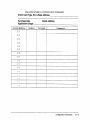
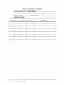
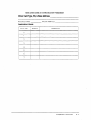
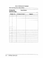
Appendix B - Configuration Worksheets
- vii -
. . . . , . . . . . . . . . . . . . . . . . . . . ;JI;
.
. : : : : : : : : : : : : : : : : : : : : : : : : 98-2
. . ~ . . . . . . . . . . . . . . . . . . . . . .9B-2
a
a
a
...
- VIII -
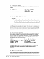
Chapter 1
INTRODUCTION
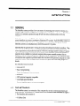
1.1
GENERAL
The MetraBus system provides a low-cost means of connecting real-world I/O devices to a
computer. The system is available in two configurations: (1) tightly coupled to an IBM PC bus
system or (2) remotely operated through RS-232/422 serial communications from any
computer.
Under the supervision of a PC, MetraBus digital, analog, and counter-timer measurement, and
control interfaces can control cost-effective industrial I/O systems. Each MetraBus system can
measure and control hundreds of analog, digital, and counter/timer I/O points. Several
MetraBus systems can simultaneously control thousand of I/O points.
MetraBus fills the gap between I/O plug-in boards and dedicated industrial controllers. Plugin boards and a personal computer are finding applications in process measurement and
control applications and product test stations. However, the large number of date I/O points
required, the proximity of the sensors to the control room combined Gith a finite number of
expansion slots available in a personal computer often require versatile systems that are
flexible, provide for enhanced expansion capability and are inexpensive. The MetraBus family
of industrial data acquisition products retains the close link of the personal computer to a data
acquisition system while offering extreme flexibility at a price that rivals many plug-in I/O
boards.
Key MetraBus features include:
1.2
l
Low cost I/O
l
Ease of programming
l
Simple packaging and interconnection
l
Reliability
l
100% personal computer compatible
l
Local, high speed interfaces
l
Remote capability, up to 1.2 km from computer
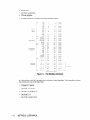
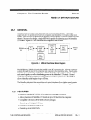
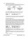
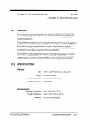
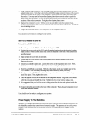
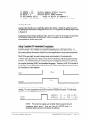
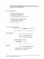
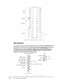
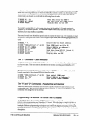
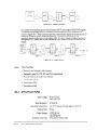
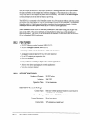
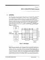
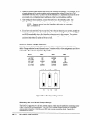
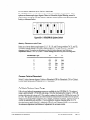
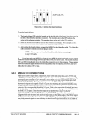
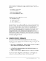
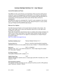
THE METRABUS
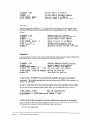
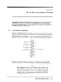
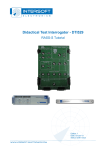
The MetraBus system is an extension of the computer bus to real world measurement and
control devices. All MetraBus I/O boards share the 5O-conductor cable illustrated in Figure l1. The MetraBus cable consists of:
l
6 Address lines
INTRODUCTION
I- 1
l
8 Datalines
l
4
l
3 Power supplies
l
Ground conductors between all address data and control
Control/status
lines
-
CONTROL
co
-c?
c2
r
CLEAR
j
!
i
WSTRB
R/W
07
AO
A:
x-2
ADDRESS
BUS
A3
K-4
A5
-
BUSY
+15 v
- 15 v
+5 ‘d
+-5 v
POWER
-
t5
+5
15
v
v
v
1
3
5
7
9
11
13
15
17
13
21
23
25
27
29
3:
33
35
37
39
41
43
45
47
49
2
4
6
8
10
12
14
16
18
20
22
24
26
28
30
32
34
36
38
40
42
44
46
48
50
7
GND.
GND.
GND.
GND.
GND.
GND.
GND.
GND.
GND.
GND.
GND.
GND.
GND.
GND.
GND.
GND.
GND.
GND.
GND.
GND.
+5 v
+5 v
+5
i5
-i5
v
v
v
I
POWE?
Figure 1-l. The MetmBus Connector
Six address lines yield 26 = 64 individual
may control any one of the following:
* 8
Digital I/O points
* One 8-bit A/D point
* One half of a la-bit A/D
* One 8-bit D/A
l
l-2
One 8-bit counter/timer
METRASUS USER MANUAL
addresses on the MetraBus. Each MetraBus address
1.3
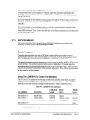
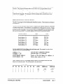
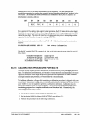
AVAILABLE METRABUS BOARDS
MetraBus I/O boards are controlled by the PC through one of the MetraBus controller/driver
cards. These I/O Boards are as follows:
l
pCMDB-64: PS/2 compatible MetraBus controller board
l
MDB-64: IBM PC compatible MetraBus controller board
MID-64: IBM PC compatible controller card with full optical isolation between PC and
MetraBus.
l
REM-64: Remote MetraBus controller. Communication via RS-232/422 serial. Multidrop
up 16 REM-64 per computer serial port.
INTMDB-64: Intelligent MetraBus controller board. This board is described in a separate
manual.
l
Both local and remote MetraBus systems control the same family of signal acquisition and
control boards. The boards and their various functions are as follows:
MID-16/M%-%:
l
16 solid-state relays
. MEM-8: 8 electromechanical relays
1.4
l
MEM-32: 32 electromechanical relays
l
MIO-32: 32-channel, optically isolated TTL output
l
MII-32: 32-channe1, optically isolated TT’L input
l
MAI-16: Wchannel, 12-bit A/D
l
MAO-8: &channel, 8-bit D/A
l
MAO-12: 12-Channel, 12-bit A/D
l
MCN-8: 8 Channel, &bit counter timer
l
MJ3B32: 32-bit prototype board with four fully decoded addresses
l
MDG-1: Diagnostic/training
l
MBUS-PWR: MetraBus power supply
l
MSSR-32: 32-channel, solid-state reIay board
l
MCPT-8X8: Cross-point relay board
l
MTHERM-20: 20-channel thermocouple
l
MTAP-1: Power supply tap board
board with LEDs
PACKAGING & INTERCONNECTION
All MetraBus I/O boards are 19” rack mountable using either the RMT-02 housing, a standard
NEMA cabinet, or any 7” x 6”~ 2” enclosure. A 50-way, 0.05” spacing ribbon cable connects the
MetraBus controller/driver card to the I/O boards. This MetraBus cable operates at lengths
of up to 100’. Connectors are standard, 50-pin insulation-displacement type; their parallel
architecture allows placement at any point along the MetraBus cable.
INTRODUCTION
1 -3
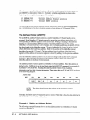
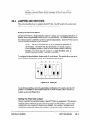
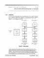
1.5
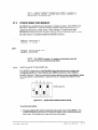
CONCEPTUAL VIEW OF METRABUS
MetraBus is an extension of the PC I/O control address space. The MetraBus controller card
implements three control functions, as follows:
* An address Ppinter
l
A data input/output
l
A reset/clear line
path
An I/O OUT command from the PC sets the address pointer to a MetraBus I/O board at its
address. Data may then move to or from the selected I/O boards. A RESET/CLEAR may
come from the PC at any time, clearing all I/O boards and resetting the address pointer to
zero.
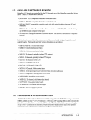
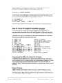
1.6
PROGRAMMING METRABUS
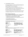
MetraBus is programmable from any PC-usable language having INPUT and OUTPUT
commands capable of manipulating the I/O bus. Examples of such languages are:
l
l
l
c
l
BASICA
Microsoft PASCAL
l
l
Assembly
GWBASIC
TURBO PASCAL
In addition, the REM-64 MetraBus controller allows connection of a MetraBus’system to any
computer with an Rs-232/RS-422 interface. A REM-64 can be controlled from any language
capable of writing and reading the computer’s serial ports.
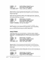
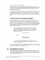
Programming the MetraBus is a two-step procedure: (1) set the address pointer then (2) read
or write the data. The following discussion wiIl use the variables DATAIO, ADRPTR, and
MRESET in order to help clarify MetraBus progr amming technique. These variables are
generally set at the beginning of your programs for ease of manipulation as follows:
lODATA
= 768
20ADRPTR = 769
30MRESET = 770
4OOU-T ADRJ?TR, 01
5OOUT DATAIO,45
‘Declare
MetraBus data I/O path
'Declare
address pointer
location
'MetraBus reset location
'Set the address pointer
to address
'Write data 45 to address 1
#l
Set the MetraBus address pointer by issuing a single comman d to the MetraBus controller
board. Once set, the address pointer is latched and need not be reset until a different address
is required.
Writing and reading data from a MetraBus I/O board is transparent once the address pointer
is set. Issuing an OUT command will write data to the targeted I/O board. Likewise, issuing
an INP command will retrieve data from the I/O board via the data I/O path.
40 OTJTADRPTR,Ol
500UT DATAIO,45
6OVAL = INP(DATAI0)
'Set address to 1
'Write data 45 to address
'Read back data from 1
1
The MetraBus controller board and all attached MetraBus I/O boards may be reset by writing
to the reset address. Here is an example in BASIC:
l-4
METRABUS USER MANUAL
40 OUT
MRESET, 00
‘Clear
the MetraBus
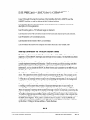
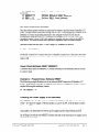
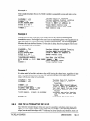
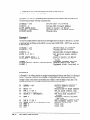
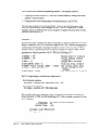
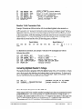
Examples of all MetraBus programming features are available on the MetraBus diskettes.
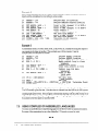
MDB-64 vs. REM-64 Programming
Direct bus plug-in controller boards (MDB-64 and MID-64) program differently than the
REM-64 MetraBus serial controller board. Commands to the MDB-64 and MID-64 are direct
statements to an I/O port. For example, in BASIC:
40 OUT ADRPTR, 01
5OOUT DATAIO, 44
‘Set address pointer
to #l
‘Write data 44 to board #l
REM-64 commands are writes to a COMl or COM2 serial port. The REM-64 has an on-board
m&!roprccessor which interprets commands from the personal computir. The REM-64 issues
commands to the I/O boards (via the MetraBus cable) identical to those issued by an MDB-64
or MID-64. For example, in BASIC:
10 PRINT #l,"B"
; 1
'Activate
REM-64 #l
PRINT #1, "A" ; 4 'Set address pointer
to MetraBus address
PRINT #l, "W" ; 44 ‘Write data “44” to I/O board #l
20
30
4
Since the MDB-64 and REM-64 use different hardware connections, programs for the MDB-64
are not compatible with those for the REM-64.
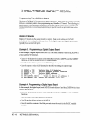
Programming
l/O Boards
MetraBus I/O boards fall into three major categories:
l
Digital in and out
l
Analog in and out
l
Counter/timer
Digital MetraBus I/O boards program with byte wide (8 bits) write and read commands.
Driving a single digital line high or reading the status of a single line requires one bit.
Therefore, 8 lines (or bits) are controlled when writing to or reading from the digital I/O
boards.
Data to a MetraBus digital ouQut board is latchtid and may be read back from the board. This
data readable feature is usable when manipulating the I/O lines, thus making digita
programming easy.
Analog output boards are controlled as an g-byte port, one byte per channel. The analog
equivalent of the &bit data is output by the DAC on the MetraBus analog output board.
Analog input for the MetraBus is full-featured, allowing user control of application specific
parameters. Prior to reading A/D data from a MetraBus MAI-16, the range channel and type
(12-bit or 8-bit) must be set. An A/D conversion is triggered by software only.
INTRODUCTION
I-
5
The MCN-8 counter/ timer board has two functions available from software: clear counter
and read counter. Writing to a counter will clear it while reading a counter will retrieve the
current count in the register.
I .7
SUMMARY
The remainder of this manual covers the individual MetraBus controller boards and I/O
function boards. The electrical interfacing and programming aspects of each board are
explained.
All explanations and example programs are as if the I/O board is under the control of an
MDB-64. The MIX-64 is a complete and simple implementation of the MetraBus concept.
The MID-64 and REM-64 embody additional features, and are treated in this manual with
programming examples for each.
The lNTMDI3-64 is an intelligent stand-alone driver/controller board for the MetraBus, It is
usable as a dedicated, low-cost controller, or as a satellite controller monitored/controkd
by
a larger host computer. This board is described in the INTMDB-64 user’s manual.
Schematics for the MetraBus are available in the MetraBus schematic package.
I-6
METRAHJS USER MANUAL
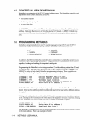
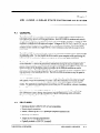
Chapter 2: The Controller Boards
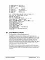
Part 2A
MDB-64 DRIVER BOARD
2A.l
GENERAL
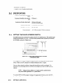
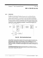
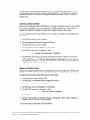
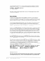
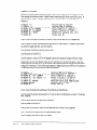
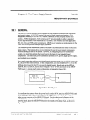
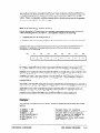
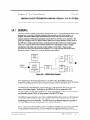
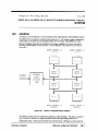
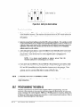
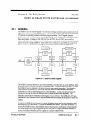
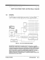
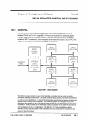
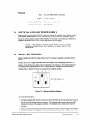
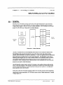
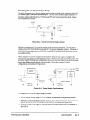
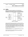
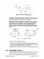
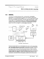
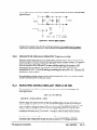
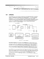
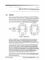
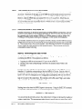
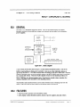
The MDB-64 driver board is the functional heart of the MetraBus system. This board
supervises all I/O operations between the computer and MetraBus I/O boards within your
system. Since the MBD-64 generates all necessary control signals, it controls system-level data
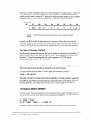
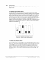
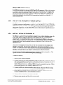
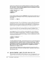
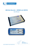
transfer. Because of its design, a single MDB-64 is capable of addressing up to 64 MetraBus
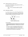
I/O boards. Figure 2A-1 is a functional block diagram of the MDB-64.
I
I
I
MFI’RABUS
TIMING
,
ADDRESS
DECODE
LOGIC
COMPUTER
EXPANSION
BUS
-
I
AND
CONTROL
SIGNAL
LOGIC
-
METRABUS
CABLE
DRIVER/
RECEIVER
-
METRABUS
CABLE
I
I
I
I
I
I
BASE
AOORESS
SWITCH
I
I
I
L-------------------------_--_-______---------------,
Figure 2A-1. MDB-64 Functional
I
Block Diagram
The MDB-64 is a ‘half-slot” board that installs in any PC expansion slot. A 50-pin connector
extends through the rear of the computer and connects to the MetraBus cable. Functionally,
MetraBus has a parallel-bus architecture with the MetraBus cable carrying all data, address,
and control signals, as well as distributing power to the MetraBus I/O boards. Ground
conductors are interleaved between all signal lines to reduce system noise. The MDB-64
allows MetraBus cable lengths of up to 100 feet.
The MetraBus industrial data acquisition and control interface allows higher speed, greater
accuracy, and total autonomous operation to otherwise slow and troublesome applications.
A.2
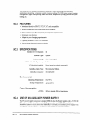
FEATURES
l
Interfaces with IBM PC/XT, PC AT or other bus-compatible computers.
l
Allows placement of MetraBus I/O boards at up to 100 feet from the computer.
l
Compatible with many off-the-shelf software packages.
l
Controls up to 512 digital I/O lines.
l
Controls up to 256 (8 or U.-bit) A/D.
l
Controls up to 64 @-bit) DACs.
THE CONTROLLER BOARDS
MDB-64 DRIVER BOARD
2A-1
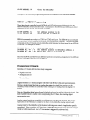
2A.3
l
Extremely cost effective.
l
Adapts to your changing requirements.
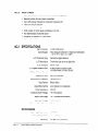
SPECIFICATIONS
Number of addressable MetraBus
ports:
64
Maximum MetraBus data transfer
rate:
80 kbytes/s
Maximum drivable cable length:
100 feet at full speed
200 feet at reduced speed
MetraBus cable type:
50 conductor ribbon cable
MetraBus connector:
3M 3425-4050
Power required:
2A.4
-+5 V: 250 rr~4 typical, 325 n-4 maximum
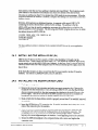
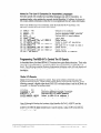
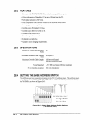
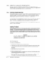
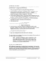
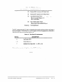
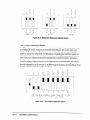
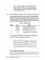
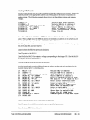
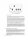
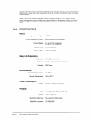
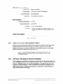
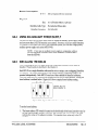
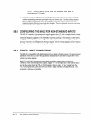
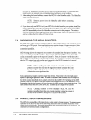
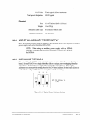
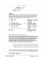
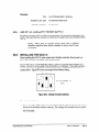
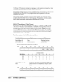
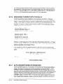
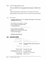
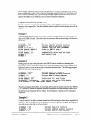
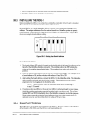
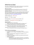
SE’TJING THE BASE ADDRESS SWITCH
The MD13-64 uses four consecutive locations in the PC I/O address space. This address space
extends from decimal 512 to 1023. The MDB-64 base address switch is preset by the factory
for 768 (3OOh),as shown in Figure 2A-2.
ADDRESS
LINE
-2
Switch
ADDRESS UNE
DECIWL
512
256
settings
indicate
512
256
i
VALUES:
HEX
200
100
o voluc
= 768
o!
Dccimoi
Figure ZA-2. Defautt Base Address Switch SettiRgs.
(768 decimal, 300h)
If I/O address 768 (300h) is occupied by another device, you must reset the base address
switch. Refer to your PC manual for available addresses in the I/O space.
Once you have selected an address, change the base address switch accordingly. For
assistance with the settings, use the INSTALLEXE program provided on your MetraBus
diskette.
NOTE: Setting the base address to a location used by another device
may cause erratic operation or PC system failure.
To run the INSTALLEXE program, change to the appropriate directory and at the DOS
prompt, and type INSTALL followed by [Enter]. When the program asks for the desired
2A-2
METRABUS USER MANUAL
base address, enter the new base address in decimal and press [Enter]. The program rounds
your address to the nearest 4-bit boundary and checks for conflicts with other devices.
Choosing an address less than 512 or greater than 1023 results in an error message. When the
program determines an address is suitable, it displays the settings you must make on the Base
Address Switch.
INSTALL.EXE performs an additional function: it generates a file named MBUS.ADR
containing the newly selected Base Address Switch settings. The address in the file
MBUS.ADR may then be read by application programs as an alternative to m-defining the
MDB-64 address in every program. The following short BASIC program shows how to obtain
the address from the MBUSADR file.
lOOPEN "KBUS.ADR" FOR INPUT AS #l
INPUT #~,BASADR
30 PRINT BASADR
40 CLOSE #l
20
The base address location is returned to the variable BASADR for use by your application
program.
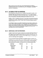
2A.5
INSTALLING THE MDB-64 FUSE.(Fl)
MBD-64 fuse Fl allows the PC to supply +5 VDC to the MetraBus I/O boards via the
MetraBus cable. Large systems and those using +15 V will require an additional high-quality
power supply such as the MBUS-PWR (see Contents). In this case, Fuse Fl must be removed.
Failure to remove the fuse when using the MDB-44 with an external power supply causes the
fuse to blow.
If the MetraBus System is to draw power from the PC power supply, the fuse Fl must be
installed. This fuse is a Littlefuse #312001,3AG 2A fast blow.
2A.6
INSTALLING THE MDB-64 DRIVER CARD
1. Unplug your computer.
2. Remove the cover of your computer and select any empty expansion slot. Remove the
backplate from the selected slot. If you are using an IBM PC/XT, note that the MDB-64
does not operate correctly in the short expansion slot farthest to the right (I8) next to the
power supply. This slot is reserved for the IBM expander card and is not available for
peripherals since the bus signals are slightly different from the other slots.
3. Make certain that the base address switch is properly set and fuse Fl is installed/removed
(as needed).
4. Lnsert the MDB-64 into a PC expansion slot. If needed, straighten the locking tabs on the
ends of the connector prior to insertion.
5. Once the board is in place, plug the MeiraBus cable into the MDB-64. Make sure the
locking tabs are locked around the mating portions of the MetraBus connector. The
mating portions of the connectors are keyed and should plug-in easily. Check the
keyways for correct alignment prior to insertion, Avoid applying force to the connector.
6. Secure the MDB-64 backplate to the computer frame with a screw and replace the
computer cover.
THE CONTROLLER BOARDS
MDB-64 DRIVER BOARD
2A-3
NOTE: The MDB-64 is shipped with two resistor networks. These
termination resistors are to be installed in sockets RN1 and RN2 on the
last MetraBus I/O board in your system. These resistor networks are
used to minimize signal reflection due to long MetraBus cable lengths.
They are optional, however, and have little effect for cables of 50 feet or
less.
2A.7
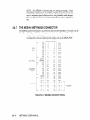
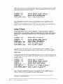
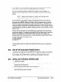
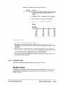
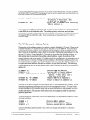
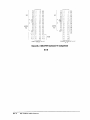
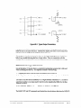
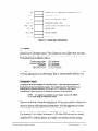
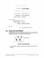
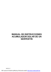
THE MDB-64 METRABUS CONNECTOR
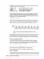
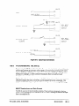
The MDB-64 passes information to and receives data from the MetraBus I/O boards via the
MetraBus cable. Figure ZA-3 shows the physical and functional layout of this cable.
NOTE: The +15 VDC pins are active only when the MDB-64 is used
in conjunction with an external power supply such as the MBUS-PWR.
1
DATA
BUS
POWER
L
BUSY
+15 v
-15
v
+5 v
+5 v
+5 v
+5 v
t5v
3
5
7
9
11
13
15
17
19
21
23
25
27
29
31
33
35
37
39
41
43
45
47
49
2
4
6
8
10
12
14
16
18
20
22
24
26
28
30
32
34
36
38
40
42
44
46
48
50
GND.
GND.
GND.
GND.
GND.
GND.
GND.
GND.
GND.
GND.
GND.
GND.
GND.
GND.
GND.
GND.
GND.
GND.
GND.
GND.
+5 v
i-5 v
+5 v
-1-5 v
i-5 v
Figure ZA-3. MetraBus Connector Pinouts
2A-4
METRABUS
USER MANUAL
POWER
2A.8
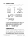
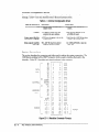
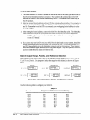
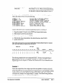
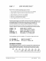
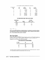
PROGRAMMING THE MDB-64
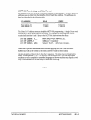
As mentioned earlier, the PC has I/O address locations for such things as disk drives,
printers, serial ports, and other peripherals. The MDB-64 Base Address is located within this
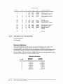
I/O space. The three MDB-64 locations and their functions are as follows:
LOCATION
I/O ADDRESS
(Decimal)
BaseAddress+-Oh
BaseAddress+lh
BaseAddress+2h
BaseAddress+3h
768
769
‘770
771
Function
Data I/O path (DATAIO)
Addresspointer (ADRPTR)
Softwarereset (PRESET)
Unassigne4l
For the sake of clarity, all references to specific address locations use the variable names
DATAIO, ADRFTR, and MRESET as specified in the table above. Normally, variable
assignments are made at the beginning of your application program. For example,
ZODATAEO = 768
20ADRPTR = 769
30WSET
= 770
'Declare
'Declare
'Declare
data I/O location
addxess pointer
location
RESET location
The following sections discuss address location functions in order of typical programming
use. All references to the above locations assume a base address of 768 decimal (300h).
The Address
Pointer (ADRPTR)
The function of the MDB-64 address pointer is to point to the specific MetraBus I/O board to
be accessed. Each MetraBus I/O Board must have a unique, non-overlapping board address
in order to identify it from other boards in the MeiraBus system. (Refer to the section “Setting
the board address” for the relevant I/O board.) Writing the board address to ADFUYIR sets
the current MetraBus address and targets the specific I/O board for use. Once the address
pointer is set to a particular board address, data can be written to or read from that board.
The BASIC commands IN? and OUT control the read and write functions respectively. It
should be noted that while the example are written using BASIC, many computer languages
supporting data I/O operations may be used. Refer to the programming manual for the
language that you are using for the correct syntax. The following example illustrates how to
set the address pointer to a MetraBus I/O board (MEM-8) at address 12.
10ADRPTR = 769
2QDATAIO = 76%
30MRELSET= 770
4OMBf8 = 12
5OOUT ADRPTR, MEM8
'Declare
address pointer
location
'Declare
data I/O location
'Declare
HetraBus RESET location
‘Declare m-8
board address
'Point to HEM-8 at address 12
Once the MetraBus address pointer is set, it does not change until another OUT command
changes it. Setting the address pointer is a fast operation on the personal computer bus,
taking less than 10 p.
Remember that the address pointer is used to point to a MetraBus I/O board address. Since
this address is latched on the MDB-64, it can be read back using the BASIC INP command, as
follows:
60ADDREXS = INP(ADRPTR)
THE CONTROLLER
BOARDS
MDB-64 DRIVER BOARD
ZA-5
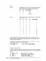
The BASIC variable ADDRESS contains the current MetraBus I/O board address. If the above
INP command were issued immediately after the previous OUT command, the ADDRESS
variable would contain a valued of 12. Reading the address pointer returns six bits of address
information and two bits of status information (R/W and BUSY), as shown below:
Address Byte
BIT
D7
D6
BUSY
R/w
D5
A.5
D4
A4
D3
D2
Dl
A3
A2
Al
DO
A0
NOTE: The driver board inverts the polarity of the actual bus control
signals.
Normally, the BUSY and R/W status bits are low (non-zero). When this is true, the data
returned is identical to the contents of the address pointer. See Programming TheMDB-64 7’0
Covttiol The I/O Boar& for an example and an explanation of how to monitor the status bits.
The Data l/O Register
(DATAIO)
Once the address pointer has been set, data may be written to and read from a MetraBus I/O
board. All data transfer takes place through DATAIO. Accessing specific functions on the
MetraBus I/O board and passing data back to the computer via DATA10 may be
accomplished using the BASIC OUT command
70 OUT DATAIO, 128
This command calls for a value of 128 which might activate a relay on the MEM-8 relay board.
The actual functions that it specifies is dependent on the board accessed.
You may read data from the data I/O with a single IN7 command, as follows:
EODAT = INP(DATAI0)
The BASIC variable DAT contains data from the MetraBus I/O board previously targeted by
the ADRPTR. All MetraBus output boards latch data sent to them and therefore, have data
readable capability. This means that if the above IN? command were issued after the
previous OUT command, variable DAT would contain a value of 128.
The Sofiware
RESET (MRESET)
A software reset causes alI MetraBus I/O boards connected to the MetraBus cable to be reset
to a known state. Seethe description of the I/O board for more details. The following shows
how to use the software RESET feature for all MetraBus I/O boards.
80 OUT HRZSET, 00
90 START = TIMER
100 IF (TIZGR - START) < .02 THEN 100
The BASIC Timer command is used to insure a wait of 20 ms for the reset pulse to finish.
214-6
METRABUS USER MANUAL
Notes On The Use Of Compiled Or Assembled Languages
Execution speeds with compiled and assembled languages may call for precautions. As
mentioned earlier, when reading the currently latched MetraBus I/O address, the lowest six
bits contain address information while the two most significant bits carry status information.
Prior to any BASIC Inp or Out command, check the status bits (R/W and Busy). The
following example shows the proper status checks.
10
20
30
40
50
60
70
80
90
100
110
120
130
140
150
DATA10 = 768
ADRPTR = 769
MRESET = 770
MA116 = 8
OUT MRESET, 00
START = TIMR
IF (TIKER - START) < .02
IF (INPUDRPTR)
AND 192)
OUT ADRPTR, HAI16+2
IF (INP(ADFU?TR) AND 192)
OUT DATAIO, 18
IF (INP(ADRPTR)
AND 192)
OUT ADRPTR, HAI16+1
IF (INP(ADRPTR)
AND 192)
AIN = INP(DATAI0)
'Declare
'Declare
'Declafe
'Declare
I/O location
address
pointer
location
MetraBus
RESET location
MAIboard address
'Input
Time
'Wait 20 ms
'Check status
'Point
to g-bit A/D resolution
'Check status
'Set gain to +5 V range on than
'Check status
'Point
to result
of conversion
'Check status
'Return
result
to computer
THEN 70
THEN 80
THEN 100
THEN 120
THEN 140
2
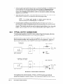
Programming The MDB-64 To Control The l/O Boards
As described above, the three MDB-64 I/O locations have quite distinct functions. Their order
of execution generally follows a consistent pattern when programming any MetraBus I/O
board. The following examples illustrate programming techniques used with both digital and
analog I/O Boards. For prograrnmin g information on a specific board, refer to the board
description.
Digital l/O Boards
Digital I/O boards are the easiest to control. Data can be written to DATAIO soon after
setting the address pointer. Digital output boards typically have several &bit ports. In the
following example, a digital output board (MIO-32) is at board address 0 and the MDB-64 is at
computer I/O Address 768 decimal (3OOh).
lODATA
= 768
20ADRPTR = 769
3OMRESET = 770
40MI032 = 0
5OOUT ADRPTR, MI032
6OOUT DATAIO, 255
'Declare
data
'Declare
address
'Declare
'Declare
I/O
location
pointer
location
MetraBus REXXT location
MIO-32 board address
'Point
to MIO-32
at address 0
'Output bit pattern
1111 1111
Lines 10 through 40 declare the locations of the MetraBus DATAIO, ADRF’TR, and the
MRESET functions, as well as declare the MIO-32 board address. Line 50 sets the address
pointer to the MIO-32 digital output board. Line 60 outputs a value of 255 to the MIO-32,
setting all outputs high.
THE CONTROLLER BOARDS
MDB-64 DRIVER BOARD
2A-7
Digital input board (Mu-32) programmin g is similar to that for digital output boards. Digital
input boards typically have several B-bit ports. After the address pointer has been set, data
can be read from the DATAIO, as follows:
lODATA
= 768
20ADRPTR = 769
30MRBSET = 770
40MII32 = 4
5OOUT ADRPTR, MI132
60DATIN = INP(DATAI0)
'Declare
'Declare
'Declare
'Declare
'Point to
'Get data
Data I/O Location
Address Pointer
Location
MetraBus RESET Location
MII-32 Board Address
MII-32 at Address 4
from DATA10
Lines 10 through 40 declare the locations of the MetraBus DATAIO, ADKPTR, and the
MRESET functions, as well as declare the MU-32 board address. Line 50 sets the address
pointer to the MIl-32 digital input board. Line 60 reads the contents of one of the four &bit
ports on the m-32 and stores the result in the BASIC variable DATIN.
Analog
I/O Boards
Analog output boards (MAO-8) use one MetraBus I/O address per channel. Setting the
Address Pointer to the appropriate address and writing data to the DATAIO will produce an
analog output. The following example shows how to set the address pointer and output a
voltage.
lODATA
= 768
20ADRPTR = 769
30MRESET = 770
4OMAO8 = 8
5OOUT ADRPTR, MAO8
6OOUT DATAIO, 255
7OOUT DATAIO, 0
8OOUT ADRPTR, MA116
'Declare
'Declare
'Declare
'Declare
'Point
'Output
'Start
'Select
Data I/O Location
Address Pointer
Location
MetraBus RESET Location
MAO-8 Board Address
to HAO-8 at Address 8
Pull Range Voltage
A/D Conversion
the MSB's address
Lines 10 through 40 declare the locations of the MetiaBus DATAIO, ADRPTR, and the
MRXSET functions, as well as declare the MAO-8 board address. Line 50 sets the address
pointer to channel 0 of the MAO-8 board. Line 60 outputs the highest voltage possible for its
selected range.
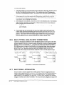
Analog Input boards (MAI-16) require additional steps, however, in order to set the gain and
resolution for the desired channel prior to taking data. Assume an MAI- board has been set
at Board Address 8.
lODATA
= 768
'Declare
Data I/O Location
20ADRPTR = 769
'Declare Address Pointer
Location
30MRESET = 770
'Declare MetraBus RESET Location
35MAI16 = 8
'Declare MAIBoard Address
4OOUT ADRPTR, KAI16+2'Point
to 8-bit A/D resolution
SOOUT DATIO,18
'Set gain to + 5 V range on channel
6OCUT ADRPTR, MAI16+1'Point
to result
of conversion
90AIN = INP(DATAI0)
'Return result
to computer
2
Lines 10 through 35 declare the locations of the MetraBus DATAIO, ADRPTR, and the
MXESET functions, as well as declare the MN-16 board address.
Line 40 selects the gain/channel selection mode for the board at address 8 (see MN-16
description for full explanation).
2A-a
METRABUS
USER MANUAL
Line 50 sets the gain to + 5V full scale range on channel 2.
Line 60 points to the B-bit conversion mode for the board and channel previously selected.
Line 70 starts the A/D conversion process.
Line 80 points to the results of the A/D conversion.
Line 90 returns the result to the computer and stores the data in the variable AJN.
THE CONTROLLER
BOARDS
MDB-64 DRIVER BOARD
2A-9
cl
P
2A-10
METRABUS
USER MANUAL
Part 2B
Chapter 2: The Controller Boards
MID-64 DRIVER BOARD
2B.l
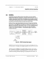
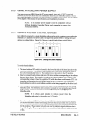
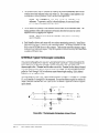
GENERAL
The MID-64 driver board optically isolates the computer bus from the MetraBus data
acquisition and control system. The MID-64 supervises all I/O operations between the
computer and MetraBus I/O boards within your system. All necessary control signals are
generated within the MID-64, so you don’t have to worry about system level data transfer.
Because of its design, a single MID-64 is capable of addressing up to 64 MetraBus I/O boards.
The MID-64 contains an on-board, programmable counter/timer capable of periodic system
interrupt generation. This allows the MetraBus operation in a foreground/background mode
emulating many common multitasking environments. A functional block diagram of the
MlD-64 is provided in Figure 2B-1.
r--------------------------------------------------------------------~
COMPUTER
EXPANSION BUS
:
I
PC
BUS
-
ADDRESS
OECOOE
LOGIC
-
METfZABUS
TIMING
AND
CONTROL
SIGNAL
LOGIC
-
ISOLAlORS
MEmABuS
CABLE
DRIER/
RECEIVER
!
’
?-+
Mmus
CABLE
1
BASE
ADDRESS
WITCH
Figure 2B-1.
MID-64 Functional
Block Diagram
When installed, a 50-pin connector extends out the rear of the computer and connects to the
MetraBus cable. Functionally, the MetraBus has a parallel bus architecture with the MetraBus
cable carrying all data, address, and control signals, as well as distributing power to the
MetraBus I/O boards. Ground conductors are interleaved between all signal lines to increase
system noise immunity. The MID-64 has been designed to allow MetraBus cable lengths of up
to loo feet.
The MetraBus industrial data acquisition and control interface, in conjunction with your
present computer, allows higher speed, greater accuracy, and total autonomous operation to
previously slow, troublesome, applications.
THE CONTROLLER
BOARDS
MID-64 DRIVER BOARD
2B-1
2B.2
28.3
FEATURES
l
Connects with IBM PC/XT, PC AT, or other bus compatible computers.
l
Allows placement of MetraBus I/O at up to 100 feet from the PC.
l
Full optical isolation to 500 Volts.
l
Fully compatible with software written for the MDB-64 driver board.
l
Interrupt generation capability.
l
Controls up to 512 digital I/O lines.
l
Controls up to 256 (8 or 12-bit) A/D.
l
Controls of 64 @-bit) DACs.
l
Controls up to 64 counter/timers.
l
Extremely cost effective.
l
Adapts to your changing requirements.
SPECIFICATIONS
Number of Addressable MetraBus
Ports:
64
Maximum MetraBus Data TrmR;yz
80 kbytes/s
Maximum Drivable Cable Length:
100 feet at full speed
200 feet at reduced speed
Power Required:
PC to MetraBus Isolation:
2B.4
+ 5 V: 250 mA typical, 325 rnA maximum
500 volts (minimum)
SETTING THE BASE ADDRESS SWITCH
The MID-64 uses four consecutive locations in the PC I/O address space. This address space
extends from decimal 512 to 1023. The MID-64 Base Address Switch is preset by the factory
for 768 (3OOh),as shown in Figure 2A-2.
ADDRESS
LINE
qs
i
iedicote
256
0 value
= 766
o!
Decimal
or
+ iOD = 300
Hex
Figure 2B-2. Default Base Address Switch Settings.
(768 decimal, 300h)
2B-2
METRABUS
USER MANUAL
If I/O address 768 (300h) is occupied by another device, you must reset the base address
switch. Refer to your PC manual for available addresses in the I/O space.
Once you have selected an address, change the base address switch accordingly. For
assistancewith the settings, use the INSTALLEXE program provided on your MetraBus
diskette.
NOTE: Setting the base Aadress to a location used by another device
may cause erratic operation or PC system failure.
To run the INSTALL.EXE program, change to the appropriate directory and at the DOS
prompt, and type INSTALL followed by [Enter]. When the program asks for the desired
base address, enter the new base address in decimal and press [Enter]. The program will
round your address to the nearest 4-bit boundary and check for conflicts with other devices.
Choosing an address less than 512 or greater than 1023results in an error message. When the
program determines an address is suitable, it displays the settings you must make on the base
address switch.
INSTALL.EXE also generates a file named MBUSADR containing the newly selected base
address switch settings. The address in the file &!fHJS.ADR may then be read by application
programs as an alternative to redefining the MID-64 address in every program. The
following short BASIC program shows how to obtain the address from the MBUS.ADR file.
1OOPKN "MBUS.ADR" FOR INPUT AS #1
20 INPUT #l,BASADR
30PRINT BASADR
40 CLOSE #l
The base address location is returned to the variable BASADR for use by your application
program.
2B.5
USE OF THE AUXILIARY POWER SUPPLY
An auxiliary power supply such as the MBUS-Pm is required for operation of the MID-64,
since it does not distribute power from the computer’s supply. Seethe chapters of this
manual dealing with the MBUS-PWR for specifications and installation instructions.
2B.6
INSTALLING THE MID-64 DRIVER CARD
1. Unplug your computer.
2. Remove the cover of your computer and select any empty expansion slot. Remove the
back-plate from the selected slot.
3. Make certain that the base address switch is properly set.
4. Insert the MID-64 into the expansion slot. It may help to straighten the locking tabs on the
ends of the connector prior to insertion.
THE CONTROLLER BOARDS
MID-64 DRIVER BOARD
28-3
5. Once the board has been inserted, plug the MetraBus cable into the MID-64. Make sure
that the locking tabs are locked around the mating portions of the MetraBus connector.
The mating portions of the connectors are keyed and should plug-in easily. Check the
keyways for correct alignment prior to insertion. Avoid applying force to the connector.
6. Secure the MID-64 back-plate to the computer frame with a screw and replace the
computer cover.
NOTE: The MID-64 is shipped with two resistor nehvorks. These
termination resistors are to be installed in sockets RN1 and RN2 on the
last MetraBus I/O board in your system. These resistor networks are
used to minimize signal reflection due to long MetraBus cable lengths.
They are optional, however, and have little effect for cables of 50 feet or
less.
2B.7
THE MID-64 METRABUS CONNECTOR
The MID-64 passesinformation to and receives data from the MetraBus I/O boards via the
MetraBus cable. Figure 2B-3 shows the physical and functional layout of this cable.
NOTE: The +15 VDC pins are active only when the MID-64 is used in
conjunction with an external power supply such as the MBUS-PWR.
m
D-1
m
m
r
DATA
BUS
m
iz
tie
m
L
CLEAR
WSTRB
CONTROL
C
ADDRESS
BUS
%
1
3
5
7
9
11
13
15
17
19
21
23
25
27
29
31
33
35
37
39
4’1
43
45
47
49
r -iii
/
A2
23
i
A5
XT
r
POWER
i
BUSY
+I5
v
-15
v
i5 v
+5 v
+.5 v
+5 v
+5 v
2
4
6
8
IO
12
14
16
18
20
22
24
26
28
30
32
34
36
38
40
42
44
46
48
50
GND.
GND.
GND.
GND.
GND.
GND.
GND.
GND.
GND.
GND.
GND.
GND.
GND.
GND.
GND.
GND.
GND.
GN3.
GN3.
GND.
+5 v
+5 v
+5 v
+5 v
+5 v I
Figure 28-3. The MetraBus Connector
28-4
METRABUS USER MANUAL
POWER
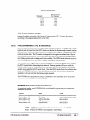
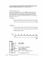
2B.8
PROGRAMMING THE MID-64
As mentioned earlier, the PC has I/O address locations for such things as disk drives,
printers, serial ports, and other peripherals. The MID-64 base address is located within this
I/O space. The eight MID-64 locations and their associatedfunctions are as follows:
LOCATION
I/O ADDRESS
(DecimaI)
BaseAddress+Oh
BaseAddress+lh
BaseAddress+2h
BaseAddress+3h
Base-4~Uress4h
BaseAddress+5h
BaseAddress+6h
BaseAddress+7h
768
769
770
771
772
773
774
775
Function
Data I/O pPath (DATAIO)
AddresspPointer (ADRXR)
SoftwarerReset(MRESET)
Unassigned
counter 0 (COUNTO)
Counter 1 (COTJNTI)
Unassigned
CountercContro1(CNTCTRL)
NOTE: Most applications do not require counter/timer interrupt
implementation. For those that do, a short section is included in this
manual.
The discussion below will deal with the majority of
applications and wiIl, for the moment, ignore interrupt
implementation.
There are three important address locations:
Address pointer (ADRF’TR)
Data I/O path (DATAIO)
Software reset (MRESET)
The following sections discuss address location functionality in order of typical programming
use. All references to the above locations will assume a base address of decimal 768. For the
sake of clarity, all references to specific address locations will use the variable names
DATAIO, ADRPTR, and MRESET as specified in the table above. Normally, variable
assignments are made at the beginning of your application program, as follows:
1ODATAIO = 768
20ADRPTR = 769
30MRESET = 770
The Address
'Declare
‘Declare
‘Declare
Data I/O Location
Address Pointer
Location
RELSETLocation
Pointer (ADRPTR)
The function of the MID-64 address pointer is to point to the specific MetraBus I/O board to
be accessed. Each MetraBus I/O board must have a unique, non-overlapping board address
in order to identify it from other boards in the MetraBus system. (Refer to the section “Setting
the Board Address” for the relevant I/O board.) Writing the Board Address to ADRPTR sets
the current MetraBus address and targets the specific I/O board for use. Once the address
pointer is set to a particular board address, data can be written to or read from that board.
The BASIC commands INP and OUT control the read and write functions respectively. It
should be noted that while the examples are written using BASIC, many computer languages
supporting data I/O operations may be used. Refer to the programming manual for the
THE CONTROLLER
BOARDS
MID-64 DRIVER BOARD
28-5
language that you are using for the correct syntax. The following example illustrates how to
set ADRF’TR to address 12 for a MEM-8 board:
10 ADRPTR = 769
20DATAI0
= 768
'Declare
'Declare
'Declare
40MEMB = 22
50 OUT ADRPTR, KEN8
‘Declare
30MRESET = 770
'Point
address pointer
location
data I/O location
MetraBus RESET location
MEN-8 board
address
to MELM-8at address
12
Once the MetraBus address pointer is set, it does not change until another OUT command
changes it. Setting the Address pointer is a fast operation on the personal computer bus,
taking less than 10 microseconds. Since this address is latched on the MID-&, it can be read
back using the BASIC INF’ command, for example:
60 ADDRESS = INPCADRPTR)
The BASIC variable ADDRESS contains the address of the MetraBus I/O board currently
targeted. If the above INP command is issued soon after the previous OUT command, the
ADDRESS variable would contain a value of 12. Reading the address pointer returns 6 bits of
address information and two bits of status information (R/W and BUSY), as follows:
AddressByte
BIT
NOTE:
D7
D6
BUSY
Pu’W
D5
A5
D4
D3
D2
Dl
A4
A3
A2
Al
DO
A0
The driver board inverts the polarity of the actual bus control
signals.
Normally, the BUSY and R/W status bits will be low (non-zero>. When this is true, the data
returned is identical to the contents of the address bus. See Programming TheMID-64 To
Control The I/O Boards for an example and an expknation of how to monitor the status bits.
The Data I/O Register
(DATA/O)
Once the address pointer has been set, data may be written to and read from a targeted
MetraBus I/O board. All data transfer takes place through DATAIO. Accessing specific
functions on the MetraBus I/O board and passing data back to the computer via DATA10
may be accomplished using the BASIC OUT command:
7OOUT DATAIO,
128
This command outputs a value of 128 which might activate a relay on the MEM-8 relay board.
The actual functions that it specifies is dependent on the board accessed.
Data can be read from the Data I/O with a single lNP con-man d, as follows:
80DAT = INP (DATAIO)
The BASIC variable DAT wiIl contain data from the MetraBus I/O board previously targeted
by the ADRM’R. All MetraBus output boards latch data sent to them and therefore, have data
2B-6
METRABUS
USER MANUAL
readback capability. This means that if the above INP command were issued after the
previous OUT command, variable DAT would contain a value of 128.
The Software
RESET (MRESET)
A software reset causes all MetraBus I/O boards connected to the MetraBus cable to be reset
to a known state. Seethe description of the I/O board for more details. The following shows
how to use the software RESET feature for al1MetraBus I/O boards.
80 OUT MRESET, 00
90 START = TIMER
100 IF (TIMF,R - START) < .3 THEN 100
The BASIC Timer command is used to insure a wait of 300 ms for the reset pulse to finish.
Notes On The Use Of Compiled Or Assembled Languages
The execution speed of compiled and assembledIanguages calls for precautions. As
mentioned earlier, when reading the currently latched MetraBus I/O address, the lowest six
bits contain address information while the two Most Significant Bits carry status information.
Prior to any BASIC Inp or Out command, you should check the status bits (R/W and Busy).
The following example shows the proper status checks.
10
20
30
40
50
60
70
80
90
100
110
120
130
140
150
DATA10 = 768
ADRPTR = 769
MRESET = 770
MA116 = 8
OUT MRESET, 00
START = TIMER
IF (TIMER - START) < .3 THEN 70
IF (INJ?(ADRPl'R) AND 192) TEEN 80
OUT ADRPTR, MAI16+2
IF (INP(ADRPTR)
AND 192) TW3N 100
OUT DATAIO, 18
IF (INP(ADRmR)
AND 192) TWEN 120
OUT ADRPTR, MA116+1
IF (INP(ADRPTR)
AND 192) THEN 140
AIN = INP(DATAI0)
'Declare
'Declare
'Declare
'Declare
I/O location
address
pointer
location
MetraBus
RESET location
MAIboard
address
'Input
Time
'Wait 300 ms
'Check status
'Point
to B-bit
A/D resolution
'Check status
'Set gain to +5 V range on than
'Check status
'Point
to result
of conversion
'Check status
.'Return
result
to computer
2
Programming The MID-64 To Control The I/O Boards
As described above, the eight MID-64 I/O locations have distinct functions. Their order of
execution generally follows a consistent pattern when programming any MetraBus I/O board.
The following examples illustrate programmin g techniques used with both Digital and
Analog I/O Boards. Detailed programmin g information on a specific board, refer to the board
description.
Digital I/O Boards
Digital I/O boards are the easiest to control. Data can be written to DATAIO soon after
setting the Address Pointer. Digital output boards typically have several 8-bit ports. In the
following example, a digital output board (MIO-32) is at board address 0 and the MID-64 is at
computer I/O Address 768 decimal GOOh).
THE CONTROLLER
BOARDS
MID-64 DRIVER BOARD
28-7
IODATAIO = 768
20ADRPTR = 769
30MRESET = 770
40MI032 = 0
50 OUT ADRPTR, MI032
60OUT DATAIO, 255
'Declare
Data I/O Location
'Declare
Address Pointer
Location
'Declare
MetraBus RESET Location
'Declare
MIO-32 Board Address
'Point to MIO-32 at Address 0
'Output bit pattern
1111 1111
Lines 10 through 40 declare the locations of the MetraBus DATAIO, ADRPTR, and the
MRESET functions, as well as declare the MIO-32 board address. Line 50 sets the address
pointer to the MIO-32 digital output board. Line 60 outputs a value of 255 to the MIO-32,
setting all outputs high.
Digiti input board programming is similar to that for digital output boards. Digital input
boards (MII-32) typically have several &bit ports. After the address pointer has been set, data
can be read from the DATAIO, for example:
1ODATAIO = 768
20ADRPTR = 769
30HRESET = 770
4OMII32 = 4
5OOUT ADRPTR, MI132
60 DATIN = INP(DATAI0)
'Declare
'Declare
'Declare
'Declare
'Point to
'Get data
Data I/O Location
Address Pointer
Location
MetraBus RESET Location
MII-32 Board Address
MII-32 at Address 4
from DATAIO
Lines 10 through 40 declare the locations of the MetraBus DATAIO, ADRPTR, and the
MFZSET dictions, as well as declare the MI-32 board address. Line 50 sets the address
pointer to the MII-32 digital input board. Line 60 reads the contents of one of the four &bit
ports on the m-32 and stores the result in the BASIC variable DATIN.
Analog
l/O Boards
Analog output boards (MAO-8) use one MetraBus I/O address per channel. Setting the
address pointer to the appropriate address and writing data to the DATAIO will produce an
analog output. The following example shows how to set the address pointer and output a
voltage.
lODATA
= 768
ZOADRPTR = 769
30MRESET = 770
4OMAO8 = 8
5OOUT ADRPTR, MAO8
600UT DATAIO, 255
'Declare
Data I/O Location
'Declare
Address Pointer
Location
'Declare MetraBus RESET Location
'Declare MAO-8 Board Address
'Point to MAO-8 at Address 8
'Output Full Range Voltage
Lines 10 through 40 declare the locations of the MetraBus DATAIO, ADRPTR, and the
MR.ESETfunctions, as well as declare the MAO-8 board address. Line 50 sets the address
pointer to channel 0 of the MAO-8 board. Line 60 outputs the highest voltage possible for its
selected range.
Analog input boards (MAI-16) require additional steps, however, in order to set the gain and
resolution for the desired channel prior to taking data. Assume an MAI- board has been set
at Board Address 8.
10DATAIO = 768
'Declare
Data I/O Location
20ADRPTR = 769
'Declare
Address Pointer
Location
30MRESET = 770
'Declare
MetraBus RESET Location
35MAIl6 = 8
'Declare
MAIBoard Address
4OOuT ADRPTR, MAI16+2'Point
to 8-bit A/D resolution
28-8
METRABUS
USER MANUAL
500UT DATI0,18
'Set gain to + 5 V range on channel
600UT ADRPTR, MAI16+1'Point
to result
of conversion
to computer
'Return result
90AIN = INP(DATAI0)
2
Lines 10 through 35 declare the locations of the MetraBus DATAIO, ADRPTR, and the
MFCESET functions, as well as declare the MAI-
board address.
Line 40 selectsthe gain/channel selection mode for the board at address 8 (see MAIdescription for full explanation).
Line 50 sets the gain to + 5V full scale range on channel 2.
Line 60 points to the &bit conversion mode for the board and channel previously selected
Line 70 starts the A/D conversion process.
Line 80 points to the results of the A/D conversion.
Line 90 returns the result to the computer and stores the data in the variable AIN,
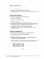
Interrupt Generation Via The 8254 Counter/Timers
The following discussion is for MetraBus users familiar with the 8254 and its associated
registers as well as IBM PC interrupts and interrupt service routines. Seethe 8254 Data Sheet
for further information.
For this discussion, we will simply show how to generate the interrupt. It is left to the user to
actually implement interrupt functionality. There are several good books dealing with IBM
PC interrupts and how to service them as well as vector tables and related interrupt
information, such as: Inside the IBM PC by Peter Norton and Assembler for the IBM PC and
PC-XT by Peter Abel.
The MID-64 has an INTEL 8254 programmable interval timer I.C. in conjunction with a 6 MHz
clock. The output from these counters may be connected to the PC bus. The counter can be
programmed to generate periodic interrupts for any of the IBM PC interrupt levels 2 through
7. This allows an interrupt service routine to be controlling the MetraBus in the background
while the computer is doing some other function in the foreground.
Timing is accomplished as follows: the output of counter 0 is cascaded to the input of counter
1 creating a 32-bit counter (this provides a maximum interrupt time of once every 11.9
seconds). The output from counter 1 is brought to the interrupt jumpers on the MID-&l.
There are typically 6 interrupt levels number 2 through 7, (level 1 is reserved). Level 2 has the
highest priority if more than one peripheral is requesting interrupt service at the same time.
To enable an interrupt request (IRQ), simply connect the counter output to the computer bus
by placing the IXQ level jumper on the desired level. Then, write the desired control word to
the 8254 control register. Next, point to counter 0 and/or counter 1 via the ADRPTR and
write a data word (clock multiplier) to the high and low byte registers of the 8254. This sets
up the tuner. Writing to the base address +7 starts the timer.
THE CONTROLLER
BOARDS
MID-64 DRIVER BOARD
26-9
cl
28-10
METRABUS
USER MANUAL
Chapter 2: The Controller Boards
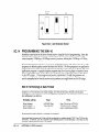
Part 2C
pCMDB-64 DRIVER BOARD
2C.l
GENERAL
The pCMDB-64 MetraBus controller board allows you to integrate your IBM PC System 2
(PS/2) computer (models 50 through 80) with a MetraBus industrial data acquisition and
control system. The MetraBus system is a low-cost solution for slow, troublesome data
acquisition applications.
The pCMDB-64 Board supervises all I/O operations between the PS/2 and the.MetraBus I/O
boards in your system (refer to Chapter 1 for a list of compatible boards). One pCMDB-64
board controls up to 64 external MetraBus I/O boards. The lKMDB-64 is capable of
controlling up to 512 Digital I/O lines, 256 (8 or 12 bit) A/D lines, and 64 (8 bit) D/A lines.
All timing and control signals are generated from the pCMDE-64.
The lKMDB-64 is easily programmable using any of the following languages: C, BASICA,
Microsoft Pascal, TURBO PASCAL, Assembly, or GWBASIC. A Utility Disk, containing
sample programs, is provided with the @vIDB-64 to aid in creating custom programs.
2C.2
SPECIFICATIONS
Physical
Size:
Weight:
MetraBus Cable Type:
MetraBus Connector:
11.50” L x 3.47’ H (29.17 cm L x 8.61 cm H)
18 ounces (509.40 g.)
50-Conductor Ribbon cable.
3M 3425-6050
Environmental
Operating Temperature:
Storage Temperature:
Humidity:
THE CONTROLLER
BOARDS
+32 to +158” F (0 to +70” C)
-104 to +212” F t-40” to +lOO”C)
0 to 95%, non-condensing
pCMDB-64
DRIVER BOARD
2c-1
2C.3
USE OF AN AUXILIARY POWER SUPPLY
If you have more than one MCPT-8x8 or other MetraBus I/O boards installed in your
MetraBus system or do not wish to use the PC +5 V power, an auxiliary power supply may be
required. Refer to the MBUSPWR sections for more information.
2C.4
SYSTEM CONFIGURATION
The jKMDB-64 design is in accordance with the IBM PS/2 POS (Programmable Option Select)
rules and there are no user jumpers or switches. The Board Identifier Number (602Bh) is
registered with IBM. If you need a special ID number for O.E.M. applications, contact our
technical support department as instructed in Instrz~tions For FLZC~~~
Rams .
If you are familiar with installing peripheral boards in your PS/2, you may want to skim over
most of this section. It is important, however, that you read the section Configuring the
System. The system configuration procedure differs slightly from typical ones.
If you have never installed a peripheral board in your PS/2, you might find it helpful to have
your PS/2 User’s Guide handy.
Installing The Board
Before installing the pCMDI3-64, be sure that you have created a working diskette containing
the @602b.ADF file and the contents of the IBM PS/2 Reference Disk (provided with your
computer). This section provides general instructions for installing the pCMDB-64 Board. For
more detailed information regarding installation of peripheral boards, refer to the Installing
options section of the IBM Personal System/2 Model XX Quick Reference provided with your
computer.
WARNING
DO NOT ATTEMPT TO INSERT OR REMOVE ANY ADAPTER
BOARD WITH THE COMPUTER POWER ON, OR YOU RISK
DAMAGING YOUR COMPUTER!
IBM PS/2 Model 50
To install the pCMDB-64 Board,
1. Turn off power to the PS/2 and to all attached options.
2. Unplug the power cords of the PS/2 and all attached options from the electrical outlets.
Note where all the cables and cords are attached to the rear of the system unit, and
disconnect.
3. Make certain the cover lock is unlocked.
4. Remove the cover of the PS/2.
5. Choose an available option slot. Loosen the screw at the base of the blank adapter plate.
Then slide the plate up and out to remove.
6. Hold the lKlvIDB-64 in one hand. With the other hand, touch any metaIlic part of the
PS/2 cabinet. This will safely discharge any static electricity from your body.
2c-2
METRABUS USER MANUAL
7. Align the gold edge connector with the edge socket and the back adapter place with the
adapter plate screw. Note that a slot in the pCMDB-64 edge connector mates with a key in
the socket, located at the front of the computer. Gently press the board downward into
the socket. You may need to loosen the adapter plate screw more in order to push the
board fully into the socket. Do not be concerned if ~CMDB-64 connector does not use all
sections of the socket connector. Re-tighten the adapter plane screw.
8. Replace the computer’s cover. Tilt the cover up and slide it onto the system’s base,
making sure the front of the cover is under the rail along the front of the frame. Install the
two mounting
screws.
9. Plug in all cords and cables. Turn the power to the computer back on.
You should now be ready to configure your system.
I5MPS/2Mod&60and80
To install the pCMDB-64 Board,
1. Turn the power to the PS/2 and to all attached options OFF.
2. Unplug the power cords of the PS/2 and all attached options from the electrical outlets.
Make a note of where all the cables and cords are attached to the rear of the system unit
and disconnect.
3. Make certain the cover lock is unlocked.
4. Loosen the two cover screws with a coin (these screws should remain in the cover).
Remove the cover.
5. Choose an available option slot. Loosen the screw on the expansion slot cover. Then,
slide the cover out and remove. Store the cover in a safe place for future use.
6. HoId the pCMDB-64 in one hand. With the other hand, touch any metallic part of the
PS/2 cabinet. This will safely discharge any static electricity from your body.
7. Firmly press the JKMDP&I board into the expansion slot connector until the adapter
clicks into place. Then, tighten the screw.
8. Find the square cut-outs in the bottom of the computer cabinet. Align the cover latches
with the cut-outs and install the cover. Tighten the two cover smews using a coin.
9. It is suggested that you lock the cover to help protect the devices and options inside the
computer.
10. Connect all cables and cords to the rear of the computer. Then, plug all computer power
cords into electrical outlets.
You should now be ready to configure your system.
Power Supply To The MetraBus
BecauseI’S/2 design specifications limit power draw from the MicroChannel Bus, power for
the MetraBus system must come from an external supply. The presence of an active power
suppIy to the MetraBus can be monitored, however, by using the power supply control
register.
THE CONTROLLER
BOARDS
pCMDB-64 DRIVER BOARD
2C-3
The ~Ch4DB-64 is electro-optically coupled to the +15 volt line of the MetraBus. If the +-15
volts is absent, a bit in the control register will be read high (1). Note that a low control bit
does not insure that the +15 volts is within specification nor that the + 5 and -15 volts are
present at all.
Creating a Back-Up Disk
Before you do anything with the pCMDB-64, it is strongly advised that you back-up your IBM
PS/2 model XX reference disk and the MetraByte CMDR-64 utility disk. This procedure is
detailed in the IBM PS/2 operator’s manual and is briefly outlined in this section.
To copy the reference disk, make certain you have a blank, unformatted, 2.0 MB high-density
disk. Then,
1. Turn OFF the power to your computer.
2. Place the reference disk into the floppy disk Drive A.
3. Turn ON the power to your computer.
4. The IBM logo will now be displayed. Press [Enter].
5. The IBM PS/2 main menu will appear. Select
2.
Backup the Reference
Diskette
6. The IBM PS/2 w-ill prompt you through the backup procedure. When you receive the
message,remove the copy of the Reference Disk. Label the copy
Copy complete....
and use this from now on. DO NOT WRIT&PROTECT THIS DISK! Be sure to place the
original Reference Disk in a safe place.
Making a Working Copy
Becauseyour origina reference disk is write-protected, you can not copy any .ADF files onto
it. Therefore, you must use the copy of the reference disk you created. Gather your copies of
the reference disk and the utility disk and follow these steps:
1. Turn the power to your computer OFF.
2. Place the copy of the reference disk in floppy disk Drive A.
3. Turn the power to your computer ON.
4. The IBM logo will now be displayed. Press [Enter].
5. The IBM PS/2 main menu will appear. Select
5.
Copy an Option
Diskette
Press IEnter].
6. The PS/2 will prompt you through creating a working disk. When copy complete.
appears, turn OFF the power to the computer.
You are now ready to install the pCMDB-64 Board.
2C-4
METRABUS USER MANUAL
..
Configuring The System
Before configuring your system, you should have made a working diskette and installed the
pCMDB-& Board. To configure the 1.~cMYDl3-64
Board,
1. With your computer OFF, place the working disk in floppy disk Drive A.
2. Turn ON the power to the computer. The computer will now run its memory check.
After the memory check has been run, the Error Code 165. . . Adapter
Configuration
Error appears followed by two beeps. This indicates that the
computer has recognized a change of configuration. Press [Enter].
3. You now need to configure the system. If your current system configuration
allows you
to assign a base address of 300h to the pCMDB-64 Board, you can automatically configure
the system. To do this, at the prompt Run Automatic
Configuration
press Y .
4. If a base address other than 300h must be assigned, press N at the Run Automatic
configuration
prompt. This returns you to the main menu.
5. In the main menu, select
3.
Set
Configuration
6. This enters you into the configuration menu. Select
2.
Change
Configuration
7. Use the cursor keys to scroll down through the configuration list until you reach
MetraByte
PCMDB-64 MetraBus
Controller
with the slot in which it is installed.
Highlight the base address. Use IF51and [F6] to select the desired address.
If you need help making this decision, press [Fll.
8. Press [FlO] to store the configuration
in RAM.
9. Remove the working disk from the drive and store it in a safe pIace.
The system should now be configured. Upon power-up, the computer will boot normally and
you will have full use of the pCMDB-64.
NOTE: Although the pCMDB-64 is capable of supporting up to 255
choices of Base Addresses, its @602b.ADF file contains only 16. This is
because IBM’s setup program allows a choice of only 16 different Base
Addresses. If you wish to use a base address other than what appears
in the menu, you can modify the @602b.ADF file.
Modifying The @6028.ADF File
IBM’s configuration program allows 16 possible choices for each selection. In the caseof the
base address, the p.CMDB-64 supports 255 possible choices for any named item. If the default
selections are not to your liking, use the GENADFXXE to generate a .ADF file including your
choices of base addresses. Be sure to copy the .ADF file to your working disk and proceed
with the configuration procedure described above.
THE CONTROLLER
BOARDS
~CMDB-64
DRIVER BOARD
2c-5
Common Configuration
Errors
If you have taken short cuts and skipped steps, you may have already encountered an error
message. Table 4-1 lists and describes some of the most common errors.
Table 4-I. Common Configuration
ERROR MESSAGE
Errors
SOLUTION
MEANING
Lomputer dOf.Sn’trecogmzeme
adapterboard.
Ke-lnstau and Conngure the
system.
Two adapterboardshavebeen
assignedthe sameaddress.
Selectanotheraddressfor the
/.LCMDB-@board.
Setup cannot find the
appropriate .ADF file
.ADF doesnot appearto be on the
working disk.
Verify that the .ADF fiIe hasbeen
copied to the working disk.
Setup cannot read the
The .ADF ftie hasbeenaltered
using the incorrect syntax.
Use GENADFEXE to alter the
.ADF file.
lb3
* Conflict
.ADF file.
System Connections
This section describes the connectors and cables used in making the system connections. The
CMDR-64 is equipped with a DB37F’connector which is used to interface the board to the
MetraBus. Figure 2C-1 describes each signal conductor in the connector.
58
Fl
D?
06
1
3
5
7
9
11
i3
15
i7
19
Ez
DATA
BL’S
F4
El
m
r
BUSA-4
x5
CLEAR
WSTRB
Rp
CONTROL
l-
r
z
7E
A3
ADDRESS
-
POWER
-
BUSY
+15 v
-15
v
+5
G-5
+5
+5
+5
Figure 2Gl.
2C.6
METRABUS
USER MANUAL
v
v
v
v
v
L
21
23
25
27
29
31
33
35
37
39
41
43
45
47
49
GND.
GND.
2
4
6
8
10
12
14
IS
18
GND.
GND.
GND.
Gi\;D.
GKD.
GND.
GND.
GND.
GND.
GND.
GND.
GND.
GNC.
GND.
GND.
GND.
GND.
GND.
+5 v
-4-5 v
i5
v
15 v
+5 v i
20
22
24
26
28
30
32
34
36
38
40
42
44
46
48
50
J
MetraBus Connector Pin-outs
POWER
Once you have installed the l04IX3-64 Board and have configured it properly, you will need
to connect the Board to the MetraBus I/O Boards Make this connection using either the
MetraBus adapter cable (MetraByte Part #UCM-37-50) or a 37-Pin MetraBus cable (MetraByte
Part #UCM-104-7).
If you are using the 37-Pin MetraBus cable, plug the end with the 37-pin D-type connector into
the 37-pin connector on the back of the lKMDB-64 board. Then connect the other end to the
MetraBus.
If you have elected to use the adapter cable, you will also need a standard MetraBus cable.
Plug the end of the adapter cable with the 37-pin connector into the connector on the rear of
the lKMDB-64 board. Then, connect the other end (with 50-pin connector) into one end of the
standard MetraBus cable.
2C.5
PROGRAMMING
This section describes how to program the @viDB-64. Examples are provided when
necessary to clarify syntax or programming procedures.
Sample Programs
The utility disk provided with your ~.FCMDB& contains additional sample programs
illustrating the features of the various MetraBus I/O boards. Refer to these programs if you
have any difficulty programming the @MD’&64 to accomplish a specific task.
The sample programs and their descriptions can be accessedby typing: BASICA MENU at the
system prompt. You are then presented with a menu of Met&us I/O Boards. Select the
appropriate board by following the instruction list on your computer screen. After you select
a board, an introductory description of the program will appear. Then, follow the instructions
on the screen to run the program.
Using The PCMDB-64 To Control The MetraBus
The PS/2 has I/O locations for such things as disk drives, printers, serial ports, and other
peripherals. The lKMDB-64 base address is located within this I/O space. The $MDB-64
responds to four byte addresses during normal operation. Table 4-2 describes these.
Table 4-2. pCMDB-64 I10 Addresses
I/O ADDRESS
FUNCTION
VARIABLE
NAME
READ
DATA
WRITE
DATA
BaseAddress+0
Data I/O Path
DATAIO
DataIn
BaseAddress+ 1
AddressPointer
ADRmR
Address+ Status
DataOut
BaseAddress+2
BaseAddress+ 3*
PowerCheck/Reset
MRESET
PO.3Byte 102
Address
Reset
* This address is unassigned.
THE CONTROLLER BOARDS
PCMDB-64 DRIVER BOARD
ZC-7
All references to specific address locations will use the variable names DATAIO, ADRPTR,
and MRESET as indicated in Table 3-1. Normally, variable assignments are done at the
beginning of your application program. For example:
10 DATAIO=768
20 ADRPTR=768
30 MRESET=770
'Declare
'Declare
'Declare
Data I/O Location
Pointer
Location
Address
RESET Location
The following sections discuss address location functions in order of typical programming
use. All references to the above locations assume a base address of 768 decimal (300h).
The Address
Pointer
(ADRPTR)
The lXMDB-64 Address Pointer points to a specific MetraBus I/O Board function to be
accessed. Most MetraBus I/O boards respond to more than one address (typically 4 or 2)
corresponding to different registers on the same board. Writing or reading to the different
registers on a board initiates different actions or transfers different sets of data. Each
MetraBus I/O board must have a set of unique, non-overlapping addresses to identify it from
the other boards in the MetraBus system. The set of addresses for a board is set by a switch
which determines the board base address. (Refer to the section of the MetraBus manual
describing the specific I/O board.) The base address fixes the address of the first board
register and the address of successive registers is found by adding 1 to the previous address.
Once the MetraBus address pointer is set, it does not change until another OUT command
changes it. The actual time necessary for the address pointer to latch and stabilize the
MetraBus address is less than 10 microseconds.
The address pointer is used to point to a MetraBus I/O board address. Since this address is
latched on the CMDR-64, it can be read back using the BASIC INF command, for example 60
ADDRESS = lNl?(ADRFTR). Reading the address pointer returns 6 bits of address
information and two bits of status information. These status bits are R/W and BUSY as shown
in the following diagram.
Adress Byte
BIT
NOTE:
signals.
D7
D6
BUSY
R/W
D5
A5
D4
D3
D2
Dl
A4
A3
A2
Al
DO
A0
The driver board inverts the polarity of the actual bus control
Normally, the BUSY and R/W status bits are low (zero). When this is true, the data returned is
identical to the contents of the address bus.
Example
1. Setting
an
Address
Pointer
The following example illustrates how to set the address pointer to a MetraBus l/O board
(MEM-8) at address 12.
ZC-8
METRABUS
USER MANUAL
10 ADRPTR=769
'Declare
Location
20 DATAIO=768
'Declare
30 MRESET=770
'Declare
40 MEM8 = 12
'Declare
50 OUT ADRPTR, MEMB'Point
to
The Data l/O Register
Address
Pointer
Data I/O Location
MetraBus
Reset Location
HEX-8 Board Address
MEM-8 at Address
12
(DATAIO)
Once the address pointer has been set, data may be written to and read from a MetraBus I/O
board. Ail data transfer takes place through the DATAIO. Accessing specific functions on the
MetraBus I/O board and passing data back to the computer via the DATA10 may be
accomplished using the BASIC OUT command, for example 70 OUT DATAIO, 128. This
command outputs a value of 128 which might, for example, activate a relay on the MBM-8
relay board. The actual function that it specifies is dependent upon the board accessed.
Data can be read from the Data I/O with a single INP comman d, as follows:
80 DAT = IXW(DATAI0)
The BASIC variable DAT contains data from a MetraBus output board. This means that if the
above INP command is issued after the previous. OUT command, variable DAT will contain a
value of 128.
Power ChecWSofMare
R&SET (MRESET)
A software reset causesall MetraBus I/O boards connected to the MetraBus cable to be reset
to a known state.
Example
2. Programming
a
Software
RESET
The following example illustrates use of the software RESET feature for all MetraBus I/O
boards. Note that the value 00 is an arbitrary value and has no significance except as a space
marker following the mandatory comma.
80 OUT MRESET, 00
Checking
the Power Supply
to the MetraBus
The MRESET value also allows you to read Bit 7 of the POS byte 102. This contains the state
of the + 15 volt power supply. If the bit contains a 1, power is OFF. If the bit holds a 0, then
the power is ON.
Note that the absence of a status bit does not guarantee the quality of the power supply. Its
main utility is to determine if the remote power supply has been inadvertently shut-off.
By ANDing 128 with the read MRESET Address, the state of the external power supply can be
determined, for example:
THE CONTROLLER BOARDS
pCMDB-tX DRIVER BOARD
x-9
70 STATUS = INP(MRJZSET) AND 128 'check power status bit
80 IF STATUS = 1 THEN PRINT "POWEROFF";
'flag problem
Programming The pCMDB-64 Board
The three l.KMDB-64 I/O locations have distinct functions. Their order of execution generally
follows a consistent pattern when programming any MetraBus I/O board. The following is a
brief overview of programmin g techniques associated with the various types of I/O boards.
Detailed information concerning programmin g of specific boards are provided later in this
manual.
Digital l/O Boards
Digital I/O boards are the easiest boards to control. Data can be written to DATA10
immediately after setting the address pointer. Both digital output and digital input boards
typically have several 8-bit ports.
Example
3. Programming
a Digital Output
Board
In this example, a digital output board (MIO-32) is at Board Address 0 and the pCMDB-64 is
at base address 768 (decimal).
l
Lines 10 - 40 declare the locations of the MetraBus DATAIO, ADWTR, and the MRBSET
functions, as well as declare the MIO-32 board address.
l
Line 50 sets the address pointer to the MIO-32 digital output board.
l
Line 60 outputs a value of 255 (decimal) to the MI032 setting all outputs high.
10
20
30
40
50
60
DATA10 = 768
‘Declare Data I/O Register
ADRPTR = 769
‘Declare Address Pointer
location
MRESET = 770
‘Declare RESET address
MI032 = 0
‘Declare RIO-32 board address
OUT ADRPTR, MI032
'Point to MIO-32 at address
OUT DATAIO, 255 ‘Output bit pattern
‘1111 1111‘
Example
4. Programming
0
a Digital input Board
In this example, the digital input board (MII-32) board address 0 and the lKMDB-64 is at base
address 768 (decimal).
l
l
Line 40 declares the board address of the MI132.
l
Line 50 sets the address pointer to the MLI-32.
l
2c-10
Lines 10 - 30 declare the locations of the MetraBus DATAIO, ADFFI’R, and the MRBSET
functions.
Line 60 reads the contents of the &bit port and stores the result in the BASIC variable
DATIN.
METRABUS
USER MANUAL
10
20
30
40
50
60
DATA10 = 768
'Declare
Data I/O Register
ADRPTR = 769
'Declare Addxess Pointer
location
MRFSET = 770
'Declare
RESET address
'Declare MIX-32 board address
MI132 = 4
OUT ADRPTR, MI132
'Point
to MI-32
at address 4
'Store contents
of 8-bit
port in DATIN
DATIN = INP(DATAI0)
Analog
Boards
Analog output boards use one MetraBus address-per channel. Setting the address pointer to
the appropriate address and writing data to the DATAIO will produce an analog output (refer
to Example 5).
Analog input boards require additional steps, however, in order to set the gain and resolution
for the desired channel prior to taking data. Refer to Example 6 for an illustration of
programming an Analog input board.
Using Compiled Or Assembled Languages
Execution speeds with compiled and assembled languages may call for precautions. As
mentioned earlier, when reading the currently latched MetraBus I/O address, the lowest six
bits contain address information while the two most significant bits carry status information.
The R/W bit goes high (non-zero) during a data write transfer for 10 microseconds.
Additional data should not be written or read from the DATAIO while the R/W status bit is
non-zero. The address pointer can be read, however, to determine when the R/W status bit
returns to zero. 10 microseconds is very fast compared to BASIC interpreter execution speed
for compiled (including BASIC) and assembled languages. Therefore, the R/W bit should be
monitored in all non-interpreted computer languages. Refer to the following timing diagram
for visuahzation of this sequence.
IO,!&
R/W
4
5vs
WSTRB
1
Several MetraBus boards use the BUSY status bit to indicate that their data is not ready for
reading. Two such examples are the MAI- and the MTHERM-16 boards. The following
diagram shows the BUSY bit for the l&41-16.
APPROX.
APPROX.
3USY
20 ,,s
30 ps
FOR 8-BIT
FOR 12--BIT
NOTE: The actual bus signals are inverted from the status bits and
waveforms shown above. Note also that the WSTRB signal is a
hardware feature and can not be found via software.
THE CONTROLLER BOARDS
j.GMDB-64 DRIVER BOARD
2c-11
When monitoring the status bits or when only status information is required, ANDing the
address pointer with 192 ( 27 + 26 = 192) returns the desired status information, as follows:
90STATUS = INP(ADRPTR) AND 192
100 PRINT STATUS
The BASIC variable STATUS contains either 0,64,128, or 192 indicating the state of the D7
and D6 (the two MSBs) bits.
Device Interface
To aid the user in writing software for the lKMDB-64, on the PS/2, a device interface is
included in the pCMDB-64 demo programs. The interface is essentially a device driver which
can pass the base address to user-written code. The interface greatly aids the user in porting
code from computer to computer with possibly different kCMDB-64 board settings.
The device interface gets installed during boot-up of the computer. The interface can handle
up to five different uCMDB-64 boards in the system. The following is sample syntax for
loading the device interface in the DOS CONPIG.SYS file with the first board at address 300h.
DEXICE = MDB64DI.SYS/B:&h300
{/B:BASE
#2.../B:BASE
#5)
In this case, the MDB64DI.SYS file is assumed to be in the boot drive. A path may be added to
search for the file in other directories. The /B: tells the driver that the number following is a
base address in either hex “&H” or decimal format. The driver requires at least one lKMDB64 to be present and checks each l.KMDB-64 base address against values stored in the I’S/2
Prog-ran-unable Option Select (POS) registers. After finding a match, the device interface goes
on to match the next base address in line. If an error is encountered, the computer will beep
and display the text in question with an explanatory message.
The ECONFIG.EXE program generates a new CONFIG.SYS file while preserving the old in a
file called C0NPIG.BA.K. Before running ECONPIG.EXE, make sure that the device interface
program MDB64DI.SYS is on your boot disk.
To read information about an individual pCMDB-64 once all ~Ch4DB4-h check successfully, a
unique ID name is opened and can be read like a file with a record size of four bytes. During
boot-up, the interface assigns an ID name starting from “MDB64IDl” up to “MDB64ID5,”
corresponding to each Base Address appearing in the CONFlG.SYS file. Note that the
interface accepts ID name WDB641D” which always returns information about the @~4DB-64
referenced by “MDB64IDl”. In BASIC, this would look as follows:
xxx00
xxx10
xxx20
xxx30
xxx40
OPEN "KDB64IDx" AS #l LEN=4 ‘open device interface
FIELD #I,2 AS B$,2 AS H$
‘describe
the interface
‘read in the interface
information
GET #l
'GET base address
to an integer
BASE=CVI(B$)
'GET host 0 - PC/AT, 1 - PS/2
HOS=CVI(H$)
for board
record
x
POS Byte Format
This section describes the POS (Programmable Option Select) addresses to which the lKMDB64 will respond upon power-up. Table 4-3 lists and describes each POS byte address used.
2c-12
METRABUS
USER MANUAL
Table 4-3, POS Byte Addresses
POS ADDRESS(hex)
FUNCTION/FORMAT
100
Returns 2BH - low byte of ID (Read Only)
101
Retums60H - high byte of ID (Read Only)
102
Card Enable (Read/Write)
Bit 7: MetraBus Power Status (1 = OFF, 0 = ON)
Bits l-6: not used (Read as l’s)
Bit 0: Card Enable
103
Base Address (Read/Write)
Bits O-7:Top byte of base address
Bottom byte of base address always 0
104 and up
Not implemented
The PS/2 interrogates the I/O cards to determine their type by reading the lower two bytes of
the board registers. The third byte is a control register with the bit assignments as indicated in
Table 4-4 (it can also be read at base address +2).
Table 44. Third Byte Bit Assignments
DESCRIF’TION
BIT NO.
0
Card Enable (R/W)
1-6
Unused (Readas 1)
Men-&us Power Status(RO) (I= Off, 0 = On)
7
The fourth byte contains the high byte of the lKMDB-64 address.
THE CONTROLLER
BOARDS
pCMDB-64 DRIVER BOARD
2C-13
26-14
M ETRABUS USER MANUAL
Part 2D
Chapter 2: The Controller Boards
REM-64 DRIVER BOARD
2D.1
GENERAL
The REM-64 is one of four available controller/driver boards for use with the MetraBus
industrial data acquisition and control system. As the serial communication card for the
MetraBus, it allows MetraBus compatibility with virtually all makes and models of computers
regardless of manufacturer. Remote control of the MetraBus system is possible for distances
of up to 5000 feet. Data transfer rates of up to 19.2 kBaud are attainable between the computer
and the REM-44 while internal MetraBus data transfer rates exceed 80 kBaud.
Rs232C and (20 mA current loop) and W22 protocols are supported with user selectable
baud rate, bus control signal enable/disable (CTS, RTS, DTR, etc.), parity check, data format
echo/no echo, etc. Every REM-64 has two RS-232 and two RS-422I/O ports allowing up to 16
REM+% to be operated from a single computer I/O port. Twc LEDs on the REM-64 indicate
the status of the on-board microprocessor, as well as the activity status of the REM-64
(whether it is the currently active REM-W. A functional block diagram of the REM-64 is
provided in Figure 2D-1.
RS-422
OR
CURRENT
LOOP
SERIAL PORT
I
I
I
I
I
I
RS-232,
M-+
’
REM-64
SERIAL PORT
INTERFACES
W
MICROPROCESSOR
CONTROLLED
PROTOCOL
CONVERTER
v
METRAEUS
CABLE
DRIVER/
RECEIVER
L____-____---_____-__-__________________-----~
I
_:
I
I
I
I
I
METRABUS
50 -CONDUCTOR
CABLE
SECOND
REM-64
BOARD
UP TO 14
ADDITIONAL
REM-64
SYSTEMS
Figure 2D- I. REM-64 Functional
Block Diagram
The REM-64 supervises all I/O operations between the computer and MetraBus I/O boards
within your system. All necessary control signals are generated within the REM-64 so that the
user need not be concerned with system-level data transfer.
A 50-pin connector on the REM-64 connects to the MetraBus I/O boards via the MetraBus
cable. Functionally, the MetraBus has a parallel-bus architecture with the cable carrying all
data, address, and control signals as well as distributing power on the MetraBus. Ground
conductors are interleaved between all signal lines to increase system noise immunity. The
MetraBus has been designed to allow cable lengths of up to 100 feet.
THE CONTROLLER
BOARDS
REM-64 DRIVER BOARD
2D - 1
The MetraBus industrial data Aaquisition and control system in conjunction with your
present computer allows higher speed, greater accuracy, and totally autonomous operation in
previously slow, troublesome applications.
20.2
2D.3
FEATURES
l
Connects to virtually all computers regardless of manufacturer.
l
MetraBus remote operation up to 1.2 km.
l
Baud rates up to 19,200 bits per second.
l
Control up to 16 MetraBus systems from one serial port.
l
Control up to 512 Digital I/O lines per system.
l
Control up to 256 ( 8 or 12-bit) ADCs per system.
l
Control of 64 @-bit) DACs per system.
l
Extremely cost effective.
l
Adapts to your changing requirements.
SPECIFICATIONS
Number of Serial I/O Ports:
Serial Port Configuration:
Power Consumption
Environmental
+5 Volts:
and 20 rnA Current Loop
Data Terminal Equipment (DTE)
285 IT-IA(typical>, 325 rn.4 (max.)
+15 Volts:
30 II-& (typical), 45 mA (max.)
-15 Volts:
30 mA (typical), 45 mA (max.>
Operating Temperature:
Storage Temperature:
Humidity:
Physical
Size:
MetraBus Cable Type:
MetraBus Connector:
2D-2
i;), &si
METRABUS USER MANUAL
0 to 70” c
-55 to 4125’ C
0 to 95%, noncondensing
16x4.75inches
(40.63 x12.06 an)
50conductor ribbon cable
3M 3425-6050
2D.4
SWITCHES
This section describes the board address switch, serial bus selection switch, and the protocol
selection switch.
The REM-64 Board Address Switch
The multi-drop design of the REM-64 allows control of up to 16 REM&Is from a single
computer serial port, Every REM-64 must have a distinct bus address in order to differentiate
it from other REM&& on the serial bus. Available bus addresses range from 0 to 15 and are
selected via the board address switch located to the far left of the REM-64. The numbers silkscreened above the switch assembly indicate the values of the switches immediately below
them. The numbers have value only in the ON position. Setting the board address switch is a
matter of selecting an unused address and setting the corresponding switch(es) ON. For
example, in order to set a bus address of 4, the switch with the value of 4 immediately above it
would be turned ON while the others would be OFF. Figure 2D-2 shows the board address
switch set for a bus address of 10.
8
1
2
s
4
L
Figure 20-2. Setfing the Board Address Switch
The Serial Bus Selection Switch
The serial bus selection switch is a 3-gang DIP switch located to the right center of the REM-64
driver card. There are three available serial bus choices: RS-232C,RS-422,and 20 m4 current
loop configuration. You are not required to understand these three bus configurations to
operate the REM-64 since your choice is dictated by the available serial interface of your
computer. Check the technical reference manual for your PC to determine which of the three
interfaces you will use. Then, set the REM-64 serial bus selection switch accordingly. (See
Figure 2D-3.)
THE CONTROLLER
BOARDS
REM-64 DRIVER BOARD
2D-3
The Protocol Selection Switch
The REM-64 design provides maximum serial protocol flexibility. The protocol select switch
is an S-gang DIP switch, Iocated to the center left of the REM-64. This switch allows user
selection of data transfer rate (Baud rate) , parity, # of data bits, echo on/off, and enable
disable of various bus control lines. For the purpose of operating the MetraBus system, it is
not necessary that you understand the protocol terms or even their functionality. However,
some of these are explained in the serial communication tutorial provided in Appendix A.
Check the technical reference manual for the computer and/or serial interface card that you
are using to find out which lines are implemented at the computer end of things. Once you
have this information, set the switches on the REM-64 protocol select switch (SeeFigure 2D-4.)
to match. Table 2D-1 lists the switches and their functions.
SET FOR BUS CONTROL LINES DISABLED,
BITS, NO ECHO, NO PARITY, 4800 BAUD.
Figure 204.
2D-4
METRABUS USER MANUAL
The Protocol Selection Switch
7 DATA
Table 20-l.
Protocol Selection Switch Settings
Switch #
1,2
Function
Bus Control Lines Enable/Disable. Both switches set
to ON = Enable. Both switches set to OFF =
Disable.
3
# of Data Bits. ON = 7 Data Bits. OFF = 8 Data Bits.
4
Echo/No Echo. ON = Echo. OFF = No Echo.
5
Parity. ON = No Parity. OFF = Even Parity.
6,7,8
Baud Rate. Switches are used to select Baud Rate as
follows:
Baud Rate
6
7
300
606
ON
ON
ON
ON
8
ON
OFF
1200
ON
OFF
ON
4800
9600
ON
OFF
OFF
ON
OFF
ON
19200
OFF
ON
OFF
Protocol slection notes:
1. The REM-64 is configured to transmit 1 Stop.Bit.
2. The RS-232protocol supports all standard IBM asynchronous control lines when
ENABLED and only the transmit (pin 21,receive (pin 3), and signal ground (pin 7) when
DISABLED.
3. The RS-422protocol supports the Clear To Send (CTS) and Ready To Send CRTS)lines, in
addition to transmit, receive, and ground when ENABLED and only transmit (pins 4 and
5), receive (pins 8 and 91,and signal ground (pin 1) when DISABLED.
4. EL4 standard current loop configurations support the transmit lines (pins 9 and 11) and
the receive lines (pins 18 and 25).
2D.5 CONNECTORS
This section describes the MetraBus connector and the cerial connectors.
MetraBus Connector
The REM-64 passesinformation to and receives data from the MetraBus I/O boards via the
MetraBus cable. The MetraBus pin-out diagram below shows the physical layout of this
interface connector.
THE CONTROLLER
BOARDS
REM-64 DRIVER BOARD
2D-5
m
r-
-1
DI
52
DATA
3X
/
D5
33
57
CONT?C)L
ADDRESS
BUS
i5
17
19
2:
23
25
27
29
3i
33
35
37
39
L *,
CLEAR
WSTR B
RT
7s
-27
L
XT
33
’
ii4
Ti5
BUSY
+I5 v
-15 v
i5 v
4-5 v
FOWER i
43
45
47
49
45 v
i5 v
+5 v
L
6
8
10
12
14
16
i8
20
22
24
26
28
30
32
34
36
38
40
42
44
46
48
50
7
9
:1
13
E3
D-4
T-
4
3
5
1
GND.
GND.
GND.
GND.
GND.
GN3.
GN3.
GIN].
GN3.
GNC.
GNG.
GNG.
GNG.
GNC.
SND.
GND.
GND.
GND.
GND.
GND.
+5 v
+5 v
+5 v
+5 v
+5 v i
POWER
Figure 20-5. MetraBus Connector Pinouts
Serial Connectors
The REM-64 driver card contains four serial connectors: two are KS-232 compatible, and two
are for RS-422. Note that your PC may require a null modem, depending upon its serial port
configuration (DTE/DCE). The REM-64 is shipped as Data Terminal Equipment (DTE),
allowing connection of additional REM-&s using standard serial cables. The current loop
communication interface is not multi-drop compatible. Figure 2D-6 illustrates the pin
assignments for both the FS-232 and FS422 interfaces.
RS-232
TRANSMIT
DATA (TO)
RxEivE
CLEAR TO SEND
SET READY
DATA CARRIER
RS-422
3
(R-IS)
(CTS)
(DSR)
6
7
DEECT
(DcD)
8
DATA *
9
XMIT DATA -
:
RTS
2
XMIT DATA
XMIT DATA-
5
GROUhD
SIG GROUND
RTS-
4
SIGNAL
XMli
LOOP
2
DATA (RD)
READY TO SEND
DAiA
AND CURRENl
18
RCV DATA *
20
DATA T.RA%MlT
25
RCV 3ATA
3
mA
CURRENT
5
5
READY (DTR)
.
LOOP
Figure 20-6. Serial Connector Pinouts
2D-6
METRASUS
USER MANUAL
0
4
I
- 20
>
0:
0
l
l
6
CTS-
7
CTS
8
RCV DATA
9
RCV DATA-
Multiple REM-64 Connections
Every REM-64 contains two sets each of 135-232and RS-422connectors. Each set of connectors
is configured in parallel so that multiple REM-+ may be interconnected. In a typical multidrop wiring scheme, the REM-64.smight be networked in a ‘7”’ type system. A11REM&s in
the network monitor the serial bus at all times. Only the active REM-64, as targeted by the
board select command, decodes the REM-64 commands and enables those MetraBus I/O
boards connected to it.
2D.6
USE OF THE AUXILIARY POWER SUPPLY
The REM-64 does not draw power from the PC. As a result, an auxiliary power supply such
as Keithley MetraByte’s MBUS-PWR is required to operate the REM-64 as well as ail MetraBus
I/O Boards in your system. The use of other supplies is permitted as long as they meet the
MBU!S-PWRspecifications. Seethe MBUS-PWR section of this manual for specifications and
installation procedure.
2D.7
INSTALLATION OF THE REM-64
The REM-64 is a serial I/O board specifically designed for use with the MetraBus system. Its
level of serial protocol support is equivalent to the standard IBM PC/XT asynchronous
adapter board. You should bear this in mind when interfacing the REM-64 to other serial
devices (computer, terminals, controllers, etc.). As mentioned earlier, the use of a null modem
(crossing pins 2 and 3) may be required for devices configured as Data Communication
Equipment (DCE) .
Once you have configured your REM-f%, you will want to connect it to the computer and
MetraBus I/O Board(s). The procedure outlined below will aid in the installation of your
REM-&. You should also refer to those sections of this manual that deal specifically with the
MetraBus I/O boards that you are using for a full discussion of their functionality.
You may want to refer to the serial communication tutorial provided in Appendix A. This
explains the basics of serial communication protocol interfacing.
To instaIl the REM-&i,
1. Remove power from the computer.
2. Connect one end of your serial cable W-232 or RS-422cable) to the computer’s serial port
and secure it using the two smaIl screws on the cable connector. Connect the other end to
one of the REM-64 serial ports. Since each pair of ports is wired in parallel, it doesn’t
matter which port your use. Additional REM-&Is may be connected at any time. Follow
the procedure below for each additional REM-64 being used.
3. Connect the REM-64 to the first MetraBus cable connector. Make sure that the locking
tabs are indeed locked around the mating portion of this connector.
4. Unplug the power supply from line current prior to MetraBus cable interconnection.
Connect the MBUS-PWR to a second MetraBus connector.
5. Connect all other MetraBus I/O boards to the cable.
6. Repower your computer and plug in the power supply.
THE CONTROLLER
BOARDS
REM-64 DRIVER BOARD
2D-7
NOTE: Two resistor termination networks are shipped with every
REM-64. These resistors should be installed on the MetraBus I/O
board furthest from the REM-&. The sockets RN1 and RN2 are
provided for this purpose. These resistors minimize signal reflections
due to long cable lengths. They are optional, however, and have little
effect upon cables of 50 feet or less.
2D.8
PROGRAMMING THE REM-64 TO CONTROL THE METRABUS
Programmi ng the REM-64 uses a set of eight simple comman ds. Designed for maximum
power and flexibility while maintaining the elegant simplicity that is evident throughout the
MetraBus line, the REM-64 command syntax provides the user with immediate accessto
MetraBus I/O board functionality. The commands may be sent in either upper or lower case.
A command interpreter on board the REM-64 detects any transmitted errors in command
syntax, data parameters out of range, etc. and generates an error messagedescribing the type
of error detected. The REM-64 commands are listed in Table 2D-2.
Table 2%).2. REM-64 Commands
Function
Name
Command
B
A
Board Select
AddressPointer
Write Data
ReadData
Clear MetraBus
status
Hex
Decimal
W
R
C
S
H
D
Targetsspecified REM-64 by Bus Address.
Selectsthe specified MetraBus I/O Board.
Transmits instructions to the selectedI/O board.
Retrieves datafrom the l/O board via the REM-64
Resetsentire MefraESusto power-up status.
Retrieve current Board Addressand statusbits.
All daratransmitted and retrieved in Hexadecimal.
All datatransmitted and retrieved in Decimal.
The commands are further described below. Note that all of the provided examples are
written in IBM BASICA as irnpIemented on IBM PC/XT and PC AT compatibles. Similar
routines can be written in other languages on other computers.
When first writing application programs for the REM-64, it is
good idea to return all data to string variables. This is because typing
errors, illegal parameters, etc. are flagged by the REM-64 and error
messages are transmitted to the COMM buffer. You will never see
these messages if you assume that integer data should be returned.
Characters that are printed as integers will have a value of zero. This
could cause a great deal of wasted time if you assume that the I/O
boards are not operating correctly. Once the program is working and
debugged, change back to the integer variables.
HINT:
The “B” Command
- Board Select
Before any MetraBus I/O board can be addressed, the REM-64 must be targeted. This is done
using the B command, followed by the REM-64 address. The examples assume an
asynchronous communication board such as Keithley MetraByte’s COM-422 configured as
“COMI” and a REM-64 with an address of 4.
2D-8
METRABUS
USER MANUAL
When communicating with the REM-64 via the serial communication port on your computer,
the BASIC PRINT # and INPUT # statements may be used to respectively send information to
and receive data from the MetraBus system.
10OPEN "COM1:9600,N,8,1"
20PRINT #l,
AS #l
"B4"
'Open COMl port Q 9600 baud,
'no parity,
8 data bits,
and
'1 .stop bit as FILE #l
'Print
"B4" to FILE#I thus selecting
'REM-64 Address 4.
Once a REM-64 is targeted, commands may be issued to any MetraBus I/O boards connected
to that REM-64 via the MetraBus cable. The address pointer, write data, and read data
commands (A,W,and R respectively) are used to instruct the various I/O boards connected to
the targeted REM-64 MetraBus cable. These commands are discussed below in order of
common usage.
The “A” Comnand
- Address
Puinfer
The function of the address pointer is to point to a specific MetraBus I/O board. There are 64
available MetraBus I/O addresses that may be “pointed to” by the REM-&L Each MetraBus
I/Q board must have a unique, non-overlapping board address in order to identify it from
other boards in the MetraBus system. (Refer to the section “Setting the board address” for the
relevant I/O board.) Some MetraBus I/O boards use more than one MetraBus address, so
that caution must be exercised when setting a board address. Again, the sections of this
manual delaying with your specific I/O boards should be consulted prior to attempting use of
the REM-64 and I/O boards. Writing the board address to the MetraBus address pointer sets
the current I/O board address and targets that board for use. Once the address pointer is set
to a particular board address, data can be written to or read from the board. The following
example illustrates how to set the address point to the I/O board (an MIA-16, for example) at
address 12.
lOlREH64 =4
2OMAI16 = 12
300PEN "COM1:4800,N,7,1"
40 PRINT #l,
50 PRINT #l,
"B";lREX64
"A";MAI16
AS #l
'Declare
REM-64 address
'Declare MAIBoard Address
'Open COMl @ 4800 baud, no
'parity,
7 data bits,
and 1
'stop bit as file
#l
'Target REX-64 at Addxess 4
'Point to MA116 at Address 12
Note that in the above example we have defined the I/O board address as a variable. This is
standard programmin g technique since it allows for reassignment of any I/O board (with a
simple redefinition of the address rather than an entire restructure of the program) with the
routine that follows. This practice will be followed in aI1examples in order to make them
generally applicable.
Variable declaration is generally done at the beginning of your application program for ease
of accessas follows:
lOMEM8=0
2OMAIl = 4
3OMAI12 = 8
'Declare
‘Declare
'Declare
MEM-8 address
first
MAIaddress
second MAIaddress
Once the MetraBus address pointer is set, it does not change until another A command
changes it.
THE CONTROLLER BOARDS
REM-64 DRWER BOARD
2D - 9
The “S” Command
- Status
Since the board address is latched on the REM-f& it may be read back using the 5 command
as follows:
90
PRINT #l,
"S"
100
INPUT #l,
ADDRELSS
‘Send
Status
command to
'target
REM-64
'Get data from the
'Communication
Buffer
The BASIC variable ADDRESS contains the current MetraBus I/O board address.
Reading the status returns six bits of address information and two bits of status information.
These status bits are R/W and BUSY as shown below.
AddressByte
BIT
D7
BUSY
D6
R/W
D5
A5
D4
D3
D2
D-I
A4
A3
A2
Al
DO
A0
Normally, the BUSY and R/W status bits will be low (zero). (Note that the driver board
inverts the polarity of the actual Bus control signals.) When this is true, the data returned will
be identical to the address. The REM-64 may be used with assembled or compiled languages
with no fear of active status bits since the serial nature of the data transfer in conjunction with
communication buffer accesstimes are quite slow in comparison to A/D conversion times.
The “w” Command
- Write Data
Once the address pointer has been set, data may be written to and read from a MetraBus I/O
board. Writing to the current I/O board involves no more than sending the W command
followed by the data value corresponding to the function to be accessed(see those sections of
this manual dealing with the specific board). The following example accessesan MEM-8
electromechanical relay board and closes switch 3.
10=8=4
2OlREM64 = 0
3OOPEZi “COM1:9600,N,7,
40 PRINT #l, “B”; l-64
‘Declare
IDecLare
1” AS #l.
50 PRINT #l,"A";EEM8
60 PRINT #l, “W”; 2A3
MEX-8 Board Address
REM-64 at Address
0
'Open COMMport
as File
#l
‘Select
REX-64 at address
0
‘Point
to MEX-8
‘Activate
switch 3 of MEM-8
This program outputs a value of 8 (2*3) which closes relay number 3 on the MEM-8 relay
board (seethe MEM-8 section of this manual for a complete discussion of MEM-8
functionality).
The “R” Command - Read Data
Reading data from MetraBus input (analog and digital) boards may be accomplished through
the use of the R command. In addition, all MetraBus Output Boards contain a data readback
feature that enables the user to verify transmission
2D-10
METRABUS
USER MANUAL
of data to the board. This allows for
verification of data integrity which may become important when using a REM-64 at very high
baud rates over long distances or where the MetraBus system is used in an electrically noisy
environment. For example, if. we use the above program and wish to make sure that the
correct relay was closed we could add the following lines of code:
70PRINT #1, "R"
80 INPUT #1, RELAY
90PRINT RELAY
'Read data from the MEM-8
‘Get data from the COMMbuffer
'Display
data on the CRT
The BASIC variable RELAY will contain data from the MetraBus I/O board previously
targeted by the address pointer. All MetraBus output boards latch data sent to them, and
therefore, have data readback capability.
Data may be read from MetraBus input boards in exactly the same way. For example, to read
the status of the inputs lines from a ME-32 digital input board, the following program may be
used:
= 8
= 1
"coM1:4800,N,7,1"
40PRINT #l,"B";lREM64
50 PRINT #l,"A";MII32
60 PRINT #l,"R"
7OINPUT #l,BLOCKO
80PRSNT BLOCK0
lOMII32
2OlREM64
30 OPEN
The “C” Command
AS #1
‘Declare MII-32 Board Address
'Declare REM-64 Address
'Open COMMport as file
#l
'Select
REM-64 at address 1
'Point to MII-32
'Send data from MII-32
(block
'Get data from COMMbuffer
'Display
data on CRT
0)
- Clear MetraBus
A software reset causesall MetraBus I/O boards connected to the MetraBus cable to be reset
to a known state. This reset state is described in the section covering each MetiaBus I/O
board.
The following example illustrates use of the software RESET feature for all MetraBus I/O
boards connected to the selected REM-64 MetraBus cable.
lOOPEN "COM1:96OO,N,8,1"
20 PRINT #1, "B2"
30PRINT #l , "C"
The “H” and “D” Commands
AS #1
'Open serial
COMMport
'Select
REM-64 at address 2
'Send system CLEAR command
- Hexadecimal
and Decimal
These two data format commands can be used to specify whichever data format you are
comfortable with. The power-up/default status is decimal. A subsequent PNNT #l, “H”
command will change this to hex format.
Programming The REM-64 To Control The I/O Boards
As described above, the execution of REM-64 commands generally follows a consistent
pattern when programming any MetraBus I/O board. The following is a brief ovetiew of
programming techniques associated with the various types of I/O boards. The following
examples illustrate programmin g techniques used with both digital and analog I/O boards.
Detailed information concerning programmin g for specific boards can be found in the board’s
description.
THE CONTROLLER
BOARDS
REM-64 DRIVER BOARD
ZD-11
Digital l/O Boards
Digiti I/O boards are the easiest to control. Data can be written to the board immediately
after setting the address pointer. Digital output boards typically have several &bit ports. In
the following example, a digital output board is at boarda address 4 and the REM-64 is at
address 0.
lOMIO32 = 4
201REM64 = 0
300PEN "COM1:9600,N,8,1"
40 PRINT #l,"B";lREK64
50 PRINT #1, "A";MI032
60PRINT #l, "W255"
70CLOSE #l
AS #1
'Declare
MIO-32 address
'Declare
REM-64 address
'Open COMl port as file
#1
'Select
REM-64 at address 0
'Point
to MIO-32 at address 4
‘Output bit pattern
1111 1111
'Close file #l
Lines 10 and 20 declare the address locations of the REM-64 and MIO-32, respectively.
Line 30 opens the serial communications port as file #1 with a data I/O format of 9600 Baud,
no parity bit, eight data bits, and one stop bit.
Line 40 selects the EM-64 declared previously.
Line 50 points to the MIO-32.
Line 60 outputs a value of 255 to the digital output card setting all outputs of block 0 high.
Digital input boards, like digital output board, typically have several &bit ports. After the
address pointer has been set to the MetraBus board address, data can be read from the board
using the R command. Ln the following example, a digital input board (MII-32, for example) is
at MetraBus address 4 while the REM-64 is at address 2.
'Declare
MII-32 address
= 4
'Declare
REX-64 at address 2
= 2
3OOPEN ~COM1:9600,N,7,1"
AS #1 'Open COMl port as file
#1
40 PRINT #l,
"B"; lREM64
'Select
REM-64 at address 2
'Point
to Block 2 of MII-32
50 PRINT #l,
"A"; MI132 + 2
'Transmit
data from MII-32
60PRINT #I, "R"
'Retrieve
data from COMMbuffer
70 INPUT #l, BLOCK2
BOPRINT BLOCK2
'Display
data on CRT
'Close file
#l
90CLOSE #1
lOMII32
201-64
Lines 10 and 20 declare the addresses of the MIT-32 and the REM-&L
Line 30 opens the serial communication I/O port as file #1 at 9600baud, no parity, 7 data bits,
and 1 stop bit.
Line 40 selects the REM-64 previously declared.
Line 50 points to the MS32.
Line 60 tells the REM-64 to send the data from the MIS32 back to the computer.
Line 70 retrieves this data from the communication buffer.
Line 80 displays this data on the CRT screen.
2D-12
METRABUS
USER MANUAL
Analog
l/O Boards
Analog output boards use one of the available 64 MetraBus addresses per channel. Setting the
address pointer to the appropriate address and writing data to the board will produce an
analog output. The following exampIe shows how to set the address pointer and output a
voltage.
lOMAO = 8
202RRM64 = 8
3OOPHN "coM1:9600,N,7,1"
AS #1
40 PRINT #l, "B"; 2REM64
50PRINT #l, "A"; MAO8 +
60PRINT #l, "Wl92"
70CLOSE #l
'Declare MAO8 Board Address
'Declare REM-64 at address 8
'Open COMMport as fil.e #l
'Select RHM-64 at address
8
'Point to channel 3 of MAO-8
'Output corresponding
voltage
'Close file
#l
Lines 10 and 20 declare MAO-8 and EM-64 addresses. Notice that these addresses are the
same. This is alright since the REM-64 address is essentially an address on the serial bus and
is not related in any way to the 64 available MetraBus addresses.
Line 30 opens the serial communication port as file #1 for data transfer at 9600 baud, no parity
bit, seven data bits, and one stop bit.
Line 40 selects the REM-64 previously declared.
Line 50 points to the MAO-8 .
Line 60 tells the MAO-8 to output a voltage corresponding to the integer 192. (Seethe MAO-8
description for more information.)
Line 70 and 80 close file #l and end the program.
Analog input boards require additional steps in order to set the gain and resolution for the
desired channel prior to‘collecting data. 10
20
30
40
50
60
70
80
;:O
110
120
130
140
150
160
170
MA116 = 16
lRHM64=1
OPEN "COM1:9600,N,7,1"
AS #l
PRINT #l, "B";lREM64
PRINT #1, "A"; MAI16+2
PRINT #1, "W";l8
PRINT #I, "A'&; MA116
PRINT #l,"WOO"
PRINT #l, "A";MAI16
IIR"
PRINT #l
INPUT #l: LSB
PRINT #l, "A"; MA116
PRINT #l, "R"
INPUT #l,
MSB
CLOSE #l
AIN=MSB*16 + LSB/lB
PRINT AIN
Lines 10 and 20 declare MAI-
'Declare MAIaddress
'Declare REM-64 at address 1
'Open COMMport as file
#1
'Select REM-64 at address 1
'Point to GAIN/CH selection
mode
'Set gain to +/- 5V range on Ch 2
'Point la-bit
conversion
mode
'Starts
la-bit
A/D conversion
'Point to data LSB's
'Read data back to COMMbuffer
'Store data in variable
LSB
'Point to data MSB's
'Read data back to CONMbuffer
'Store data in variable
MSB
'Close file
#l (COMMport)
'Combine bytes to form data value
and REM-64 addresses.
Line 30 opens the serialcCommunication port as specified parameters.
Line 40 selects REM-64 at address 1.
THE CONTROLLER
BOARDS
REM-64 DRIVER BOARD
2D-13
Line 50 points to GAIN/CH select mode of MAI-16.
Line 60 sets the gain to +5 V on channel 2.
Line 70 points to 12-bit conversion mode of MAI-16.
Line 80 starts the A/D conversion process.
Line 90 points to LSB data from the A/D conversion process.
Line 100 reads the LSBs back to the computer COMM buffer.
Line 110 gets the data from the buffer and stores it is a variable LSB.
Line 120 points to MSB data from A/D conversion process.
Line 130 reads the data MSBs back to the computer COMM buffer.
Line 140 gets the data from the buffer and stores it in variable MSB.
Line 150 closes file #l (the COMM port).
Line 160 combines the LSBsand MSBs to form a single data byte.
Line 170 displays the data on the CRT screen.
There is a good deal of redundancy in the above routine that would normally be ehrninated in
actual usage. It is shown here only for the sake of step-by-step instruction. Seethe MAIfor
details concerning the various functions on the board.
Using Compiled & Assembled Languages With The REM-64
The use of compiled and assembled languages requires no special precautions when used
with the REM-64 since even at very high data transfer rates (19,200baud) the serial nature of
the data transfer combined with buffer accesstimes are magnitudes slower than most A/D
conversions. When using the IEM-64, we are, therefore, not “taIking” directly to it or any of
the I/O board but must pass through this data buffer. You can seethat with very fast
program execution times i.e., compiled. or assembled programs, you are actually monitoring
the status of the communication buffer and not I/O board activity. The S command
(STATUS) is implemented for address verification and for future use as far as the status bits
are concerned.
NOTE: If your data-monitoring routines attempt to write data or
commands to the MBB-32 while the circuitry is busy, problems will
arise. Therefore, when gathering data from slow circuitry, design your
data collection routines so that they actually retrieve data and/or polI
the BUSY bit using the S command prior to assuming that no data has
been produced. Generally, it is a good idea to have the computer
simply time-out while waiting for data from the COMM buffer. See the
IBM DOS manual for further information concerning time out
definition.
2D-14
METRABUS
USER MANUAL
Chapter 3: The Power Supply Boards
Part 3A
PWR-55/PWR-I 00 BOARDS
3A.1
GENERAL
The PWR-55 and PWR-100 are auxiliary power supplies for the MetraBus industrial data
acquisition and control system. These boards are predecessors to the newer MBLJS-PWR
board (see Chapter 3, Part B). The Pm-55 and PWR-100 supply required power for all
MetraBus I/O boards. When a PWR-55/PWR-100 is used, the only power drawn from the
host PC is for the MetraBus controller/driver card. Both the PWR-55 and the PWP-100 are 19”
rack-mountable in either a standard NEMA type enclosure or the MetraByte RMT-02.
The PWR boards furnish +5 VDC, +15 VDC, -15 VDC, and ground signals on the MetraBus
cable. PWR-55 is 55 W supply, PWR-100power is 100 W. Either board must match the
anticipated power draw of your MetraBus system. Both supplies contain AC line filters that
exceed IL478 and UL1283 specifications and comply with UL, VDE, CSA, and IEC safety
standards.
NOTE: Connect only a single power supply to a single MetraBus
cable. For a MetraBus requiring more than 100 watts of power, contact
the factory for assistance.
Input voltages of 90 to 125 VAC or 180 to 250 VAC along with input frequencies of 45 to 65 Hz
(4 to -63 Hz for PWR-100) allow the use of both U.S. and European standard line current. The
PWR-55works with either 110 or 220 VAC interchangeably, while the PWR-100 requires a
jumper change for 220 VAC operation. The jumper is clearly marked on the board. The
supplies are approximately 65% efficient while providing 4000 Vrms of isolation from
standard 120/220 VAC lines. The PWR-55 and the PWR-100 are switching type supplies with
hold times of 16 ms (20 ms for the PWR-55). Both supplies feature a soft start mode, are
current limiting and have linear regulation on all outputs. Extra line filters and optional
power capacitors are available for various applications. Contact the factory (SeeChapter 21.)
for further details concerning those applications that may require these power options.
Certain MetraBus I/O boards require the use of either power supply. Any system using the
MID-&l, or REM-64 interface/driver cards, the MAI- analog input board, the MAO-8 analog
output board, certain configurations of the MCN-8, and any MetraBus system that draws
more than 2 Amps will require the use of an auxiliary power supply.
3A.2
FEATURES
l
Plugs into any MetraBus cable connector
l
Meet UL, VDE, IEC, and CSA approval
l
90-120VAC or 180-250VAC switch selectable
l
Isolation to 4000 Vrms
THE POWER SUPPLY BOARDS
PWR-55/PWFi-100
BOARDS
3A-1
3A.3
l
AC line filter built-in
l
Status LEDs and multiple test points
l
Convection cooled
l
45-65 Hz (47 - 63 Hz for PWR-100) input allows European voltages
SPECIFICATIONS
Input Voltage:
Input Frequency:
Isolation:
Operating Temperature:
Hold up Time:
Output Ratings:
MetraBus Cable Type:
MetraBus Connector:
3A.4
90 to 130 VAC
180 to 250 VAC
47 to 63 Hz (45 to 65 Hz for PWR-55)
4000 vrms
0 - 70” C (derate 2.5% per degree over 45” C)
16 ms (20 ms for PWR-55)
5 VDC @ 12 A (5 A for PWR-55)
+15 VDC @ 3 A (2 A for PWR-55)
-15 VDC @ 3 A (2 A for PWR-55)
50-conductor ribbon cable.
3M 3425-6050
INSTALLING THE PWR-55/PWR-100
Using the PWR-55 or PWR-100 requires a line cord with a plug for the avaiIable type of power
(110/220 VAC). The cord should be long enough to reach from the wall outlet to the
MetraBus cable.
NOTE: Perform the following
conditions.
procedure only under no-power
1. Visually inspect the PWR-55 or PWR-100 for loose wires, screws, or components.
2. Secure the three line wires to the line input terminals u2) of the PWR-55/PWR-100 and
replace the plastic cover for protection. Be sure to install the green earth-ground line.
3. Select an unused MetraBus cable connector and plug the power supply into the cable,
making certain that the locking tabs on the connector are locked around the mating
portion. The connectors are keyed for your protection. Check the keyways for correct
alignment prior to plugging them together. Avoid the use of force with these connectors.
4. Plug the line cord to a source of power.
3A.5
USE OF OTHER POWER SUPPLIES
You may use power supplies other than the PWR-55/PWR-100 so long as they supplies meet
PWR-55/PWR-100 specifications.
3A - 2
METRABUS
USER MANUAL
3A.6
THE MTAP-1
The MTAP-1 is a power break-out board for the MetraBus system. The board can bring power
to the MetraBus from an external supply or can extract power from the MetraBus power
supply to support user circuitry. Three LEDs show power supply status. A green LED lights
to show that +5 V power is on, while red and yeflow LEDs display power on conditions for
+15 V and -15 V supplies, respectively.
A 3 X 1.5 inch breadboard area is included on the board to facilitate the installation of user
circuitry. Terminal posts connected to the power supply inputs are at the edge of the
breadboard area.
The MTAP-1 provides direct connections to the power distribution conductors in the cable.
To power a MetraBus system with an external power supply, plug the MTAP-1 into the
MetraBus cable and connect the supply inputs to their corresponding screw terminals on the
MTAP-1.
CAUTION
Do not connect external power supplies to any MetraBus system
containing a PWR-55 or PWR-100 board of that has Fuse FI installed
on an MDB-64.
THE POWER SUPPLY BOARDS
PWR-55/PWR-100
BOARDS
3A-3
Q
Q
3A-4
METRAEWS USER MANUAL
Chapter 3: The Power Supply Boards
Par-t 3B
MBlJS-PWR BOARDS
GENERAL
The MBUS-PWRs are auxiliary power supplies for the MetraBus industrial data acquisition
and control system. A 120 VAC version is for use in North America and carries a /NA
designation; similarly, a 220/240 VAC version is-intended for the European market and
carries a /EURO designation. Both versions are 19” rack-mountable in either a standard
NEMA type enclosure or the MetraByte RMT-02 frame. Both versions also meet applicable
IEC, UL, CSA, and VDE safety requirements. MBUS power supplies are replacements for the
PWR-100/55 and provide multiple supply operation.
The MetraBus power distribution system is modular to accommodate the needs of small and
large systems. This feature allows you to minimize the cost of power supply components
without limiting the size of the system. However, in configuring the power distribution
system, you must first estimate the power load on the basis of your intended board
complement. The three basic power distribution systems are PC power, single power supply,
and multiple power supplies.
For a small system that will use only digital boards requiring under 2 A of +5 VDC power, the
PC can power the boards directly. In this configuration, you must install fuse Fl(1 A) on the
MDB-64 driver board for the PC to power the digital boards. Boards such as the MID-64,
REM-&, MAI-16, MAO-8, and the MCN-8 require +15 or -15 VJX and must use an MBLJSPWR board. A typical small system configuration is depicted in Figure 3B-1.
1 PC
MDB-64
-i5 VDC
+
I/O
BOARD
Figure 3B-I. Small System
In a medium-size system, where the power load is under 100 W, attach an MBUS-PWR board
to the MetraBus cable. Remove Fuse Fl from the MIX-64 board, and plug the cable into
either power connector of the MBUS-PWR board. Use the other power connector of the
MBUS-PWR board to further daisy-chain I/O boards. For even power distribution under
near-full loads, place the MBUS-PWR board in the middle of the daisy chain, as shown in
Figure 3B-2.
THE POWER SUPPLY BOARDS
MBUS-PWR BOARDS
3B-1
KID-64
I/O
BOARD
ND&64
I
POWW
I/O
BOARD
-z-zm
?OVW
Figure 3B-2. Medium System
In a system whose expected power draw is beyond 100 W, use multiple MBUS-PWR supplies.
Connections for -multiple MBUS-PWR boards utilize the expansion (EXP) connectors, as
shown in Figure 3B-3. These connectors pass the communication signals to the next set of I/O
boards but isolate the power distribution structure. The MBUS-PWR power (PWR)
connectors supply system power to the ribbon cable. Be sure to properly estimate the load of
each group of I/O boards, and do not connect the PWR connectors of any two MBUS-PWR
boards.
--XL-
Y&Y-
CRoYUF
Figure 3B-3. Large System
3B.2
FEATURES
* Plugs into any MetraBus cable connector
* Designed to meet UL, VDE, IEC, and CSA requirements
0 90 to 120 VAC or 180 to 250 VAC versions
* AC line filter built-in
3B.3
l
Power Status LEDs
l
Convection cooled
SPECIFKZATIONS
Input Voltage:
Input Frequency:
Operating Temperature:
Hold up Time:
Output Ratings:
MetraBus Cable Type:
3B-2
METRABUS USER MANUAL
90 to 132 VAC
180 to 264 VAC
47 to 63 Hz
0 to 70” C (derate 2.5% per degree over 50” C)
2orns
5VDC@15A
+15VDC@4A
-15.VDC@l A
50-conductor ribbon cable.
MetraBus Connector:
Status Indicators:
+5, +15, -15 V available (green LEDs)
Terminal Blocks:
+5, +15, -15 V and common
Output Ground Jumper:
3B.4
3M 3425-6050
Float or utilities ground
INSTALLATION
NOTE: Perform the following
conditions.
procedure only under no-power
1. Visually inspect the MBUS-PWR for loose wires, screws, or components.
2. Determine the power distribution configuration and connector utilization.
3. Select an unused MetraBus cable connector and plug the power supply into the cable,
making certain that the locking tabs on the connector are locked around the mating
portion. The connectors are keyed for your protection. Check the keyways for correct
alignment prior to plugging them together. Avoid the use of force with these connectors.
4. Plug the line cord to a source of power.
5. Turn on power switch.
3B.5
USE OF OUTPUT GROUND JUMPER
To provide maximum flexibility and minimize ground loops within multiple-supply systems,
MBUS-PWR boards contain an output ground jumper. If desired, this jumper can connect the
utilities chassis ground directly to the DC common of each supply. Such a connection in no
way affects the chassis ground of the supply itself. In most cases,you will elect to minimize
system noise by floating all output commons except one-to remove ground loop paths.
3B.6
THE MTAP-I
The MTAP-1 is a power break-out board for the MetraBus system. The board can bring power
to the MetraBus from an external supply or can extract power from the MetraBus power
supply to support user circuitry. Three LEDs show power supply status.
3B.7
THE MBUS-PWR CONNECTORS
The MBLJS-PWRconnectors allow you to split the power distribution in a MetraBus system
between multiple power supplies. Using the expansion connector passesthe bus and control
signals but isolates the power structure.
THE POWER SUPPLY BOARDS
MBUS-PWR BOARDS
38-3
Z
r
til
E
m
DATA
BUS
CONTROL
G
is
L- rsi
D
C
ti
CLEAR
WSiRa
m
-3
72
w
XZ
A3DRESS
BUS
i
I
POWER
3
5
7
9
11
13
15
17
19
21
23
25
27
29
3i
33
35
37
30
4:
43
45
47
49
w
BUS'I
+15
-15
t5V
+5
i5
+5
+5
v
v
v
v
v
v
POWER
i
2
4
6
a
i0
12
14
16
it3
20
22
24
26
28
30
32
34
36
38
40
42
44
46
48
50
CONNECTOR
Jl. J3
J
GNC.
GND.
GND.
GND.
GND.
GND.
GND.
GND.
GND.
GND.
GND.
GND.
GND.
GND.
GND.
GND.
GND.
GNO.
GNC.
GND.
+5 v -+5v
1
( POWER
+5 v
c5 v
c5 v
PI N-OUT
CONTROL
ADDRESS
BUS
F/
L-
CLEAR
WSiRB
VW
r
1
2
72
x3
1
3
5
7
3
11
13
15
i7
19
21
23
25
27
29
3:
33
35
37
39
41
43
45
47
49
EXPANSION
2
4
6 :
8
70
;2 :
i4
16
18
20
22
24
26
28
30
32
34
36
38
40
42
44
46
48
50
CONNECTOR
J2, J4
Figure 38-4. MBUSPWR Connector Pin Assignments
3B-4
METRABUS
USER MANUAL
GND.
GND.
GND.
GND.
GND.
GND.
GND.
GND.
GND.
GNO.
GND.
GND.
GND.
GND.
GND.
GND.
GND.
GND.
GNC.
GND.
PIN-OUT
Chapter 4
MDI-1 G/MSS-16 SOLID STATE SWITCHING I/O SYSTEM
4.1
GENERAL
The MDI-X/M!%16 is a moduIar 2-board system providing complete optical isolation for
both high and low power switching applications. Each MDI/MSS-16 monitors and controls
16 individual I/O points via optically isolated solid-state, plug-m modules. A variety of these
modules is available for both input and output. Voltages of 120/130 VAC, 0 to 60 VDC, etc. as
weU as standard European line voltages may be sensed and controlled. Control and sense
modules are also usable on a single MSS16. Screw terminals on the MSS-16accept 12 to 22
AWG wire.
The MDI-16/M%-16 connects directly to any of the MetraBus controller/driver cards through
the MeiraBus cable. You may install the driver card in your computer while positioning the
MDI-16/M%-16 combination adjacent to its point of use for easy signal connection.
The MetraBus cable carries aII data, address, and status information, and it distributes power
on the MetraBus. A tot4 of 20 ground lines interleaved among the data and address lines
ensure noise immunity. The MetraBus system allows MetraBus cable lengths of up to 100 feet.
Remote control of the MeiraBus system is possible via the REM-64 serial driver card at
distances of 1.2 km. The MDI-lGR/MSS-16 is 19” rack-mountable in either a standard NEMA
type enclosure or the MetraByte RMT-01. The MDI-16/M%-16 mounts on any flat panel or
other flat surface.
A total of 32 MDI-16/M%-16s can connect to a single MeiraBus cable, allowing monitoring
and control of up to 512 individual I/O points. Like other MetraBus I/O boards, the MDIX/M%-16 has a data read-back aBowing the user to verify data integrity in date output
modes. For applications requiring more power than your PC can deliver, a choice of auxiliary
power supplies is available.
Some common uses of the MDI-16/M%-16 include computer control of Pump Cychng,
ON/OFF Motor Control, Energy Management, Signal Multiplexing, alarm Activation,
Temperature Cycling, Product Life Cycle testing, etc.
4.2
FEATURES
l
Interfaces directly to IBM PC/XT/AT and compatibles
l
Remote signal connections
l
Senses/Controls up to 512 I/O points per computer expansion slot
l
Extremely cost effective
l
Adapts to your changing requirements
l
Optically isolated to 1500VDC (nominal)
THE DIGITAL i/O BOARDS
MDI-1 G/MSS-I 6 BOARDS
4-1
4.3
SPECIFICATIONS
Number of I/O ChanneIs:
Isolation Type:
Isolation Rating:
I/O Module Life Expectancy:
I/O Modules Installed:
MetraBus Cable Type:
MetraBus Connector:
16
Optical
4000 Vrms typical
Infinite
None (must be ordered separately)
50-conductor ribbon.
3M 3425-6050
Environmental
Operating Temperature:
Storage Temperature:
0 to 70” c
-40 to loa0 c
Power Consumption
+5vDc:
325 n-4 (typical); 40 mA maximum
Physical
Size:
4.4
14.5 x 3.5 inches (MSS-16)
5.0 x 3.5 inches (MIX-16)
USING AN AUXILIARY POWER SUPPLY
You may power a single MDI-16/M%-16 from the PC power supply since only +5 VDC is
required. However, if you have more than one combination board in your MetraBus system
or if you have other MetraBus I/O boards, an auxiliary power supply may be required. See
the MBUS-PWR sections of this manual for specifications and installation procedure.
NOTE: If you use an auxiliary power supply in conjunction with an
MlX-64 MetraBus Controller/Driver card, remember to remove Fuse
Fl from the MDB-64.
If you use an internal power supply, be certain that the links at each end of the edge connector
of the MSS-16 are installed. You may power the MDI-16/M%-16 with an external +5 VDC
supply by removing the Links and connecting the supply to the two-position power supply
barrier block on the MSS-16.
4.5
CONFIGURING THE MSS-16
The MSS-16is a standard PB16A mounting rack for solid-state, I/O plug-m modules. Each
MSS-16 wiIl hold up to 16 solid-state I/O modules, which are available in several different
versions and may be ordered from Keithley MetraByte or several other manufacturers. When
ordering I/O modules from other manufacturers, bear in mind that the MSS-16 uses +5 VDC
4-2
METRABUS
USER MANUAL
for module activation. A short list of the various I/O modules available for the MSS-16
foIlows.
VAC OUTPUT (control)
OAC5 - 120 VAC @3 Amps
OAC5A - 240 VAC @3 Amps
OAC5A5 - 120/240 VAC @3 Amps (normally closed)
VAC INPUT (sense)
IAC5 - 120 VAC/DC @11 mA
IAC5A -240 VAC/DC @6.5 mA
VDC OUTPUT (control)
ODC5 - 60 VDC @3 Amps
ODC5A-2OOVDC@lAmp
VDC INPUT (sense)
IDC5-10to32VDC@25mA
IDC5B - 4 to 16 VDC @45 mA (fast switching)
NOTE:
The MSS-16 contains 5 A miniature replacement fuses that
may open in the event of external circuit failure.
4.6
INSTALLING THE MDI-16
The MDI-16 adapter board is available in two versions. The difference between versions is the
placement of the edge connector. The MDI-16R is a right-angle version of the MDI-16. The
MDI-16R was specificaIIy designed to aUow mounting of the two-board combination in a 19”
rack mount (a depth of 5” is required). Our RMT-02 is a straight inhne version with an overaIl
length (including the MSS-16)of 19 l/4 inches. It is commonly mounted on a flat panel of at
least 20” or it may be mounted in 24” racks.
Each MDI-X/M%-16 combination connected to a single MetraBus cable must be set to a
unique, non-overlapping MetraBus I/O board address. Each MDI-16 uses 2 of the available
64 MetraBus addresses. These are consecutive locations starting from the board address.
Setting the board address is outlined below (Figure 4-l shows a typical board address switch
setting).
Prior to installing the MDI-16/MSS-16, make certain that a MetraBus controller/driver
has been installed. These boards are described in the first section of this manual.
THE DIGITAL l/O BOARDS
MDI-16/MSS-16
BOARDS
board
4-3
32
I6
8
Figure 7-l. Setting the Board Address
To set the board address,
1. The board-address DIP switch is located in the lower left comer of every MDI-16. The
numbers silk-screened above the switch indicate the value of the switch immediately
below it. The numbers have value only in the ON position.
2. Select an unused board address and turn ON those switches corresponding to the address
that you have chosen. For example, in order to set a board address of 24, switches with
corresponding values of 8 and 16 would be ON while the others would remain OFF. It is
important to remember that each MDI-16 must be set to an unused, non-overlapping
Board Address in order to avoid address conflicts when being targeted by the driver card.
3. After setting the board address, you may connect the MIX-16 to the MSS-16. Then,
connect the MDI-16 to the MetraBus driver card via the MetraBus cable. The MetraBus
cable connector is keyed for your protection and should plug in easily. Check the
key-ways for correct alignment prior to plugging in the MetraBus cable.
4. If you have only one MDI-16 or if one of your MDI-16s is the last board in your system,
you should install the resistor terminating networks that are provided with your driver
card. The sockets marked RN1 and RN2 immediately above the MetraBus connector are
for this purpose. These resistor networks are used to minimize signal reflection due to
long cable lengths. They are optional, however, and have little effect for cables of 50 feet
or less.
4.7
PROGRAMMING THE MDI-16/MSS-16
MDI-16 progr amming is very simple due to MetraBus supervision by the driver board. Since
alI necessary control signals are automatically generated within the driver board, the user
need not be concerned with control registers, PEEKing or POKEing memory locations, shifting
bits, PUSHing or POPing stacks, learning new languages, or other system level headaches.
Refer to the driver board descriptions provided in Part 1 of this manual.
Two programs (in BASIC) are included on the MetraBus diskette. In one, MSSlG.BAS loops
through and sequentially activates each I/O module while displaying the status of all I/O
modules on the CRT su-een. The second program illustrates the BASIC OR command for
4-4
METRABUS
USER MANUAL
activating I/O modules while maintaining the status of the present module configuration.
The programs link back and forth for easy access. They are heavily commented so that even
the beginning programmer should have little, if any, trouble following the flow of logic
within. These, in conjunction with the examples below, should answer most of the question
that arise concerning MIX-16/M%-16 usage.
MDI-16 Terminology & Data Format
Like all MetraBus I/O boards, there is a standard programmin g sequence that is followed
when controlling the MDI-16/M%-16. This sequence consists of the following:
1. Targeting the MDI-16 via the ADRPTR.
2. Sending a data value (corresponding to the I/O modules to be accessed)to the DATAIO.
MetraBus treats the 16 modules on the MSS-16 as two @-bit) blocks corresponding to two
MetraBus I/O addresses. The data format for each of the two blocks is the same and
corresponds to the folio-wiig:
BIT
D7
D6
D5
CH7
CH6
CH5
D4
CH4
D3
D2
Dl
DO
CH3
CH2
CHl
CHO
Because of this arrangement, control of the various I/O modules on the board is accomplished
by writing a single byte whose value is associated with the modules to be accessed. For
example, to activate module #4 on block 0, write a data value of 16 (24 = 16) to the DATAIO.
Similarly, if we wanted to activate modules #3 and #5, we would write a value of 40 (23 + 25 =
40) to the DATAIO. To accessmodule 3 of block 1 (relays 8-151,target block one via the
ADRPTR and write a data vaIue of 8(23 = 8) to the DATAIO. This arrangement makes it a
very simple matter to specify modules using a BASIC integer variable as shown in the
examples below.
The BASIC OUT and lNP commands are used to respectively send information to and receive
information from the MetraBus I/O board. While the examples are in BASIC, they are equally
applicable to many other computer languages supporting data I/O operations such as C,
PASCAL, Assembly, and others. The following examples assume a MetraBus driver card is
installed at base address 768 (3OOh)and an MDI-16/M%-16 at board address 20.
Example 1
This example illustrates the use of a BASIC variable to sequentially accesseach relay on the
MSS-16.
lODATA
= 768
20ADRPTR = 769
30MSS16 = 20
4OOUT ADRPTR,ESSS16
50 FOR I= 0 TO 7
600uT DATAIO. 2hI
70NEXT I
THE DIGITAL I/O BOARDS
‘Declare
Data I/O location
‘Declare Address Pointex location
'Declare
MSS-16 Boaxd Address
'Point to MSS-16 at address 20
'Begin BASIC control
loop
'Sequentially
close each relay
'End control
loop
MDI-16/MSS-16
BOARDS
4-5
Example 2
Reading back the data value sent to the MSS-16 can be very useful for detecting data
transmission errors. Such might be the caseif you are transmitting data over long distances at
high baud rates or if you are in an area of excessive electrical noise. The following program
illustrates the data read-back feature. For the sake of clarity, the above program will be used
with lines added only as necessary.
1ODATAIO = &H3OO
ZOADRPTR = 769
30MSS16 = 20
40OUT ADRPTR,MSS16
50 FOR I= 0 TO 7
6OOUT DATAIO, (2*1)
70RLYCHK=INP(DATAIO)
80 IF RLYCEX <> (2*1)
90
100 NEXT I
110 END
'Declare
Data I/O location
'Declare Address Pointer
location
'Declare MSS-16 Board Address
'Point to HSS-16 at address 20
'BASIC control
loop
'Activate
"1" relay
'Get data just written
THEN PRINT "ERROR" :END
'Data integrity
check
'Close control
loop
Example 3
It is often useful to be able to activate a relay while leaving the others intact, regardless of their
state. The most efficient way to do this is to read back the state of all relays then OR those
relays with the new relay to be activated.
lODATA
= 768
20ADRPTR = 769
3OKSS16 = 20
4OOuT ADRPTR,MSS16
5OINPuT "NEW RELAY II; RLY
6ORLYSTAT = INP(DATAI0)
7OOUT DATAIO,
(2ARLY) OR RLYSTAT
80GOT0 50
4-6
METRABUS
USER MANUAL
'Declare
Data I/O location
'Declare Address Pointer
location
'Declare MSS-16 Board Address
'Point to MSS-16 at address 20
'Get user input for new relay
'Read back current
status of
'relays
'Activate
new relay
leaving
the
'old ones the way they were
for next relay
'Loop-back
Chapter 5: The Reiay Boards
MEM-8 ELECTROMECHANICAL
5A.l
Part 5A
RELAY I/O SYSTEM
GENERAL
The MEM-8 is an 8-channe1,double-pole, double-throw (DPDT) electromechanical relay board
designed for use with the MetraBus industrial data acquisition and control system. As
shipped, the board contains eight electromechanical relays with the silver-button type
contacts rated for 100 thousand operations at load (120 VAC/28 VDC at 5 A resistive). The
relays are configured with two poles normally open and two poles normally closed when in
the OFF state. Unlike solid-state relays, electromechanical relays offer zero-current leakage
when OFF. Since the MEM-8 uses industry-standard R10 type plug-in relays, it accepts
substitutions with other relays having contact ratings of your choice. There are also
provisions for relays with other than the standard 5 VDC coils (see the section describing
alternative relays). Figure 5A-1 is a block diagram of the MEM-8.
“CO--*”
NC NO C-B
NC -
A
6
B
COAOS
NO C-A
NC NO C-B
NC -
A
A
B
B
Figure 5A-1. MEM-8 Block Diagram
Screw terminals on the board will accept 12 to 22 AWG wire. The MEM-8 is 19” rackmountable in either a standard NEMA type enclosure or Keithley MetraByte’s R-MT-02remote
enclosure. T’he MEM-8 may also be mounted on any flat panel or other flat surface.
The MEM-8, like other MetraBus output boards, has a data read-back feature allowing the
user to verify data integrity. Each relay on the MEM-8 also has-an annunciator LED
associated with it so that visual verification is given when the relay is active. Upon power-up
and MetraBus system CLEAR, all relays return to the INACTIVE state.
The MEM-8 connects directly to any of the available MetraBus driver cards via a 50-conductor
ribbon cable. This MetraBus cable carries all data, address, and control signals as well as
distributing power on the MetraBus. The MEM-8 may be positioned adjacentto its point of
use (up to 100 feet from the computer) for easy signal connections.
Because of its design, the MetraBus system is capable of controlling up to 512 relays (64 MEM8s) per computer expansion slot. For those applications requiring greater power than is
available from your computer supply alone, a choice of auxiliary power supplies is available.
THE RELAY BOARDS
MEM-8 BOARD
5A-1
Various relay types may be mixed and matched within the same MEM-8 or the board may be
dedicated to a single relay type making this the most versatile, cost effective relay switching
board available.
Uses of the MEM-8 include computer control of pump cycling, ON/OF?? motor control,
energy management, signal multiplexing, alarm activation, temperature cycling, and much
more.
5A.2
SPECIFICATIONS
Relays
Quantity and Type:
Contact Material and Type:
Contact Rating:
8 DPDT
Silver-cadmium oxide buttons
5 A at 120 VAC (resistive)
5 A at 28 VDC (resistive)
Operate Time:
30 ms maximum
Release Tune:
10msmaximum
Relay Life Expectancy
Mechanical:
100 miLlion operations
Electrical:
100 thousand operations (at load)
Isolation:
1000 vnns
Operating Temperature:
0 to 70” C
Environmental
Storage Temperature:
-40 to 100” C
Power Consumption
+5vDc:
120 rnA (+180 mA per relay)
Physical
Size:
Weight:
w-2
16 x 4.74 inches (40.63 x 12.06 cm)
11.5 oz (326 g-m)
MetraBus Cable type:
5O-conductor ribbon cable
MetraBus Connector:
3M 3425-6050
METRABUS USER MANUAL
5A.3
USING AN AUXILIARY POWER SUPPLY
You may power one MEM-8 from the PC power supply, since only +5 VDC is required.
However, if you have more than one combination board in your MetraBus system or if you
have other MetraBus I/O boards, you may require an auxiliary power supply. Seethe MBUSPWR chapter of this manual for specifications and installation procedure.
NOTE: If an auxiliary power supply is used in conjunction with an
MDB-64 MetraBus Controller/Driver card, remember to remove fuse
Fl from the MDB-64.
5A.4
SETTING THE MEM-8 BOARD ADDRESS
Each MEM-8 connected to a single MetraBus cable must be set for a unique, non-overlapping
MetraBus I/O address if the driver card is to target that specific MEM-8. Setting the board
address is outlined below. Figure 5A-2 shows a typical board address switch Setting.
r
32
:6
8
L.
2
1
1
2
3
4
5
6
I
Figure 5A-2. Setting the Board Address
To set the board address,
1. The board address DIP switch is located in the lower-left side of the board just above the
MetraBus connector. The numbers silk-screened above the switch indicate the value of
the switch immediately below it. The numbers have value only in the ON position.
2. Select an unused board address and turn ON those switches corresponding to the address
that you have chosen. For example, in order to set a board address of 24, switches with
corresponding values of 8 and 16 would be ON while the others would remain OFF. It is
important to remember that each MEM-8 must be set to an unused, non-overlapping
board address in order to avoid address conflicts when being targeted by the driver card.
3. After setting the board address, connect the MEM-8 to the MetraBus driver card via the
MetraBus cable. The MetraBus cable connector is keyed for your protection and should
plug in easily. Check the keyways for correct alignment prior to plugging in the
MetraBus cable.
NOTE: It is always good practice to remove power from the
MetraBus cable prior to connecting any I/O boards.
4. If you have only one MEM-8 or if one of your MEM-8s is the last board in your system,
you should install the resistor terminating networks that are provided with your driver
card. The sockets marked RN1 and RN2 immediately above the MetraBus connector are
for this purpose. These resistor networks are used to minimize signal reflection due to
long cable lengths. They are optional, however, and have little effect for cables of 50 feet
or less.
THE RELAY BOARDS
MEM-8 BOARD
5A-3
5A.5
PROGRAMMING THE MEM-8
MEM-8 programrnin g is very simple due to MetraBus supervision by the driver board. Since
all necessary control signals are automatically generated within the driver board, the user
need not be concerned with control registers, PEEKing or POKEing memory locations, shifting
bits, PUSHing or POPing stacks, learning new languages, or other system level headaches.
Refer to the driver board destiptions provided in Part 1 of this manual.
Two programs (in BASIC) have been included on the MetraBus diskette. MEM8.BAS loops
through and sequentially activates each relay while displaying the status of all relays on the
CRT screen. The second program illustrates the BASIC OR command for activating relays
while maintaining the status of the present module configuration. The programs are heavily
commented so that even the beginning programmer should have little, if any, trouble
following the flow of logic within. These, in conjunction with the examples below, should
answer most of the question that arise concerning MEM-8 usage.
MEM-8 Terminology
and Data Format
Like all MetraBus I/O boards, there is a standard programming sequence that is followed
when controlling the MEM-8. This sequence consists of the following:
1. Targeting the MEM-8 via the ADRPTR.
2. Sending a data value (corresponding to the relays to be accessed)to the DATAIO.
MetraBus treats the eight relays on the MEM-8 as a single data byte. The relays, numbered 0
through 7, are associated with MetraBus data control lines as follows:
BIT
D7
D6
D5
CH7
CH6
CH5
D4
CH4
D3
D2
Dl
DO
CH3
CH2
CHl
CHO
Because of this arrangement, control of the various I/O modules on the board is accomplished
by writing a byte whose value is associated with the relays to be closed. For example, to close
relay #4, write a data value of 16 (24=14) to the driver board. Similarly, if we wanted to close
relays #3 and #5, we would write a value of 40 (23 + 25 = 40) to the DATAIO. This
arrangement makes it a very simple matter to specify modules using a BASIC integer variable
as shown in the examples below.
The BASIC OUT and INP commands are used to respectively send information to and receive
information from the MetraBus I/O board. While the examples are in BASIC, they are equa.lly
applicable to many other computer languages supporting data I/O operations such as C,
PASCAL, Assembly, and others. The following examples assume a MetraBus driver card is
installed at base address 768 (300h) and an MEM-8 at board address 20.
SA - 4
METRABUS
USER MANUAL
Example 1
This example illustrates the use of a BASIC variable to sequentially accesseach relay on the
MEM-8.
lODATA
= 768
20ADRPTR = 769
30-8
= 20
400UT ADRPTR,=B
50FOR I= 0 TO 7
Data I/O location
Address Pointer
location
'Declare
MEM-8 Board
Address
'Point to MEN-8 at address 20
'Begin BASIC control
loop
'Sequentially
close each relay
'End control
loop
600UT DATAIO, 2"I
70NEXT
'Declare
'Declare
I
Example 2
Reading back the data value sent to the MEM-8 can be very useful for detecting data
transmission errors. Such might be the case if you are transmitting data over long distances at
high baud rates or if you are in an area of excessive electrical noise. The following program
illustrates the data read-back feature. For the sake of clarity, the above program will be used
withlinesadded
onlyasnecessq.
lODATA
= &H300
2OADRPTR = 769
'Declare
'Declare
Data I/O location
Address Pointer
location
3O&E348 = 20
4OOUT ADRPTR,MEZG
50FOR I= 0 TO 7
'Declare
MEM-8 Board
6OOUT DATAIO, (2AI)
75 RLYCHK=INE'(DATAIO)
'Activate
'Get data
80IF RLYCHK <> (2*1)
85
9ONEXT I
Address
'Point to MEN-8 at address
‘BASIC control
loop
"I" relay
just
written
'ERROR' : END
THEN PRINT
'Data
'Cl088
95END
20
integrity
control
check
loop
Example 3
It is often useful to be able to activate a relay while leaving the others intact, regardless of their
state. The most efficient way to do this is to read back the state of all relays then OR those
relays with the new relay to be activated.
IODATAIO
20ADRPTR
'Declare
= 768
= 769
30=8
= 20
4OOUT ADRPTR,HEM8
50 INPUT "NEW RELAY "; RTJY
60RLYSTAT = INP(DATAI0)
7OOUT DATAIO.
(2*RLY)
OR RLYSTAT
8OGoTO 50
5A.6
Data I/O
location
'Declare
Address
Pointer
'location
'Declare
MEM-8 Board Address
'Point
to HEM-8 at address
20
'Get user input for new relay
'Read back current
status
of
'relays
'Activate
new relay
'the old ones the
' were
'Loop-back
for
next
leaving
way they
relay
USE OF ALTERNATIVE RELAYS
Since industry standard plug-in relays are used, it is possible to substitute other relays with
higherorlowercontactratings,contaact
types, and coilvoltages. Whenselectingaltemative
relays, bear in mind that relays with 5 V coils may be driven directly and, therefore, most cost
THE RELAY BOARDS
MEM-8 BOARD
5A-5
effectiveIy from your computer’s own internal power supply or from our PWR-55 or PWR-100
power supplies. The standard relays supplied with the MEM-8 board have 28 ohm coils and
will, therefore, draw about 1.5 A at 5 VDC with all the relays ON. This means that a PWR-100
will drive 7 boards (56 relays) if there is a possibility that all relays will be on at the same tune.
Some applications require that you power more than 56 relays without resorting to a heavier
supply. In these cases,a “super sensitive” relay may be substituted, e.g. Potter & Brumfield
type RlOS-El-Y2-J500. This relay requires only 7 mA to activate the coil. This is less then
1/2Oth the current dram of standard relay coils and allows for as many as 512 relays to be
driven from a single PWR-100.
However, it is not always possible to use relays having 5V coils. Such applications are
generally confined to either high current (7.5 or 10 A) or where low level (mV) voltages
requiring gold crossbar contacts are used. These applications may require the use of relays
with 6 V or 12 V coils. Provisions have been made for the addition of a LM-317JXvoltage
regulator mounted on a Thermalloy 6254B heat sink. The output voltage from the regulator is
set by Rll and R12, as shown on the schematic diagram provided. The regulator draws +15V
from the power supply, therefore, an auxiliary supply (PWR-55 and PWR-100) is required.
When using the optional regulator, link Wl on the MEM-8 must be removed. Thevoltage
regulator and additional components can be installed by the factory. Contact the factory for
pricing and availability. See Chapter 21.
The following list of alternative relays is intended to aid MetraBus users who are not familiar
with the various relay manufacturers and their products. As such, it does not constitute an
endorsement of any one manufacturer nor of their products. There are certainly many
excellent manufacturers that are not listed below.
Potter & Brumfield
Super Sensitive
High Current Contact
Higher Current
Low Level
RlOS-El-Y2-J500
RlO-El-X2-V28
RlO-El-W2-V185
RlO-El-PZ-V185
Other suppliers of R10 type relays include
American Zettler - series AZ420
Aromat - series JS2E
Allied - series T154 or TX3
n BB
5A - 6
METRABUS
USER MANUAL
(5 V coil, 2 A contacts)
(5 V coil, 5 A contacts)
(12 V coil, 75 A contacts)
(12 V coil, 150 n-4 contacts)
Chapter 5: The Relay Boards
Part 5B
MEM=32/A & MEM-32/W ELECTROMECHANICAL
5B.l
RELAY
SYSTEM
GENERAL
The MEM-32/W and MEM-32/A are 32channe1, SPST,relay boards for the MetraBus system.
The MEM-32/W has Mercury-wetted contacts rated at 2 A. The wetted contact configuration
of the MEM-32/W allows it to be mounted within +30” of vertical. The MEM-32/A uses
Mercury Amalgam relays that have slightly less current capability (0.5 A max.) but can be
mounted without regard to relay position. A bIock diagram of the MEM-32 is provided in
Figure 5B-1.
BOARD ADDRESS
OUTPUTS
METRABUS
CABLE
C
METRABUS
CABLE
INTERFACE
+3
OUTPUT
LATCH
4
BOARD ADDRESS
OUTPUTS
+‘I
OUTPUT
LATCH
4
BOARD ADDRESS
OUTPUTS
+0
BOARD ADDRESS t-2
OUTPUTS
Figure 5B-1. MEM-32 Functional Block Diagram
The MEM-32 boards use four consecutive addresses on the MetraBus. This allows control of
up to 16 MEM-32 boards by a single MetraBus driver board providing control of 512
independent relays. The board is divided into four &bit ports. Writing to a port loads data
THE RELAY BOARDS
MEM-32/A & MEM-32/W BOARDS
55-l
into the output latches and to the relays themselves. Reading data back from a port returns
the data currently on the output latch without changing it. This feature allows the user to
verify that data on the outputs has been received correctly. The MEM-32 has been designed
so that all relays are set in their off state at power-up.
The MEM-32 is connected to the MetraBus system via a 50-conductor ribbon cable that carries
all address, and data signals as well as distributing all power on the MetraBus. The standard
MetraBus cable is 10 feet long, and includes connectors for four interface boards. Keithley
MetraByte can also build special cabIes up to 100 feet for your application.
Screw terminals on the MEM-32 offer easy connection to user field wiring, and accept wire
sizes 12-22 AWG. The screw terminals are detachable for added easewhile installing or
removing boards. The EM-32 can be mounted in standard 1Pinch racks (such as the RMT02) or in standard NEMA enclosures.
5B.2
5B.3
FEATURES
l
32 SPSTMercury-wetted contacts (MEM-32/W)
l
32 SPSTAmalgam contacts (MEM-32/A)
l
Mercury-wetted contacts rated to 2 A at 50 watts (resistive)
l
Amalgam Contacts rated at 0.5 A at 10 watts (resistive)
l
Up to 512 outputs per expansion slot
l
100 VDC Isolation
l
Very useful for switching in high or low current applications
l
Allows very dense packaging in control applications
l
Very low cost per channel
SPECIFICATIONS
Number of Outputs:
Isolation:
Operation Time:
32 SPSTrelays
loo0 VDC
2.0 ms maximum
MEM-32/W Contact Ratings
Contact Type:
Contact Rating:
Contact Resistance:
Contact Life:
58-2
METRABUS
USER MANUAL
Mercury-wetted ( sition-sensitive, board must be
mounted +30” 0$ vertical)
50 W at 2 A or 500 VDC (resistive)
50 ms2 maximum
107 operations at rated load
MEM-32/A Contact Ratings
Contact Type:
Contact Rating:
Contact Resistance:
Contact Life:
Mercury amaIgam
10 W at 0.5 A or 200 VDC maximum
50 n-0 maximum
107 operations at rated load
Environmental
Operating Temperature:
Storage Temperature:
0 to 70” c
-40 to 100” C
Humidity:
0 to 90% noncondensing
Mounting:
The MEM-32/W must be mounted within +30* of
vertical. The MEM-32/A can be mounted at any
angle
Power Consumption
+5
+I5
5B.4
v:
510 m4 plus 22 n-4 per activated relay maximum
v:
Not used
USING AN AUXILIARY POWER SUPPLY
Because of low power drain, the MEM-32 does not require an auxiliary power supply unless
you have more than two MEM-32 boards in your system. However, if you have other
MetraBus I/O boards or more than 2 MEM-32s in your MetraBus system, you need a highquality auxikuy power supply such as the MBUS-PWR.
NOTE: If an atiiary
power supply in used in conjunction with an
MDB-64 MetraBus Controller/Driver card, remember to remove fuse
Fl from the MDB-64.
5B.5
SE-I-I-ING THE MEM-32 BOARD ADDRESS
The I/O address for each MEM-32 connected to a single MetraBus cable must be unique and
non-overlapping for the driver card to target that specific MEM-32. These addresses allow the
boards in a MetraBus system to be operated independently. Each MEM-32 uses four of the
available 64 MetraBus addresses. These four addresses run consecutively starting from the
MEM-32 board address. Setting the board address is outlined below. Figure 5B-2 shows a
typical board address switch Setting.
THE RELAY BOARDS
MEM-32/A & MEM-32/W BOARDS
58-3
32
16
8
4
SETTINGS ARE FOR
BOARD ADDRESS 20
Figure 58-2. Setting the Board Address
To set the board address,
1. The board-address DIP switch is on the far-left side of the board just above and to the left
of the MetraBus connector. The numbers silk-screened above the DIP switch indicate the
values of the corresponding individual switches; these numbers have value only in the
ON position.
2. Select an unused board address and set the DIP switch accordingly.
to set a board address of 24, switches with corresponding values of
while the others would remain OFF. Remember that each MEM-32
addresses of the 64 that are available and must be set to an unused,
address order to avoid conflicts.
For example, in order
8 and 16 would be ON
uses four consecutive
non-overlapping
3. After setting the board address, connect the MEM-32 to the MetraBus driver card via the
MetraBus cable. The MetraBus cable connector is keyed for your protection and should
plug in easily. Check the keyways for correct alignment prior to plugging in the
MetraBus cable.
NOTE: It is always good practice to remove power from the
MetraBus cable prior to connecting any I/O boards.
4. If you have only one MEM-32 or if your MEM-32 is the last board in your system, install
the resistor-terminating networks provided with your driver card. The sockets marked
RN1 and RN2 immediately above the MetraBus connector are for this purpose. These
resistor networks mmimiz. e signal reflection caused by long cable lengths. They are
optional, however, and have little effect for cables of 50 feet or less.
58.6
TYPICAL OUTPUT CONNECTIONS
The MEM-32 was designed to interface with a variety of devices. Figure 5B-3 depicts typical
output connections.
5B.7
PROGRAMMING THE MEM-32
MetraBus supervision by the driver board simplifies MEM-32 programming. Since all
necessary control signals are automatically generated within the driver board, the user need
not be concerned with control registers, PEEKing or POKEing memory locations, shifting bits,
PLJSHing or POPing stacks, learning new languages, or other system level headaches. Refer to
the driver board descriptions in this manual.
58-4
METRABUS
USER MANUAL
C)+-J - - -
- - -
CHi
__-..__-
(-Jp
- - -
(-x3
- - - . - - -
- - -
INPUT
0
INPUT
1
INPUT
2
INPUT
3
INPUT
4
TO INPUT
CHO
INVERTING
OUTPUTS
NON-INVERTING
OUTPUTS
I
TO A/O
BOARD
CHo
(
;Lc1-
TO INPUT
Figure 5B-3. Typkxl Output Connections
A program (in BASIC) is included on the MetraBus diskette. The program deals with the
MEM-32 and its associated functions. MEM32.BAS displays the status of all 32 output bits
and allows you to change any bit using the cursor keys (, , , ).
This program is heavily commented so that even the beginning programmer should have
little, if any, trouble following the flow of logic within. These, in conjunction with the
examples below, should answer most of the question that arise concerning MEM-32 usage.
MEM-32 Terminology & Data Format
Like all MetraBus I/O boards, there is a standard programming sequence that is followed
when controlling the MEM-32. This sequence consists of the following:
1. Targeting the MEM-32 and the &bit block desired via the ADRPTR.
2. Sending a data value (corresponding to the desired state of the outputs) to the DATAIO.
The MEM-32 has four blocks (numbered O-3)of eight channels (numbered O-7). In order to
select block number 2, you must specify that block when targeting the MEM-32 at its Base
Address as follows:
lOOUT ADRPTR, KEM32 + 2
'point
to block
2 of m-32
The BASIC OUT and INF’ commands send instructions to and retrieve data from the lvfEM-32.
THE RELAY BOARDS
MEM-32/A & MEM-32NV BOARDS
58-5
lODATAI0
Data I/O location
Address Pointer
location
'Declare
HEM-32 MetraBus address
'Point
to block 0 of MEM-32
'Set
the lowest 6-bits
(0011
1111)
'Declare
= 768
'Declare
ZOADRPTR = 769
3OMEH32 = 4
40 OUT ADRPTR, MEM32
50OUT DATAIO, 63
Example 1
The above example sets Bits 0, 1,2,3,4, and 5 to their active states. To sequentially toggle
(ON then OFF) each of the 32 bits of the MEM-32, use nested BASIC FOR ... NEXT loops as
follows:
lODATA
20ADRPTR
= 768
= 769
3OME!M32 = 4
40FOR I = 0 TO 3
5OOTJT ADRPTR, MI032
+ I
60FOR J = 0 TO 7
7OOUT DATAIO, 2*Y
80NBXT J
90NEXTI
'Declare
Data I/O location
'Declare
Address Pointer
location
'Declare
W-32
Board Address
'Set up block access control
loop
'Point to block "1" of m-32
'Channel access control
loop
'Set each
'Increment
'Increment
bit
sequentially
channel
block.
high
variable
and loop
Loop back to 40
Example 2
It can be useful to be able to turn certain output bits ON while leaving the other output bits in
their present state. Do this with the BASIC OR comman d as follows:
'Declare
Data I/O location
'Declare
Address
Pointer
location
'Declare
MEM-32 Board Address
'Point to block 4 of MBM-32
(bit number)
5OINPUT "Bit
number ON II ; BIT 'Get user input
'Retrieve
present
status
60OLDBITS=INP(DATAIO)
7OOUT DATAIO, 2,'BIT OR OLDBITS 'OR new bit with old
'Loop back for next bit
SOGOT 60
1ODATAIO = 768
20ADRPTR = 769
3OMEB32 = 4
4OOUT ADRPTR,MBM32 + 4
As shown above, the MEM-32 has data read-back capability allowing for data integrity
verification. This lets the user read-back the data just sent to the MEM-32 and compare it to
thedatavaluespecified.
In order to verify data via the data read-back feature, the following program will be helpful.
We will use the above program with changes Qines 10 to 50 remain the same as above).
'Turn ON targeted
bits
6OOuT DATAIO, 2ABIT
'Get data just sent
70BITCBEK = INP(DATAI0)
80 IF BITCBER <> 2*BIT THEN PRINT "ERROR! !": END
90GOTO 50
Note that in all the above examples, we used a variable to set various bits to the specified
states. Calculatingtheintegerthatrepresentsvariousbitsis
Bitcalculationsarebased
5B-6
on binaryarithmetic
METRABUS USER MANUAL
a simplematterasshownbelow.
(base21 asfollows:
Therefore, to set bits 4 and 7 ON, we would output a data value of 144 to the DATAIO, after
we had targeted the MEM-32.
4OOUT ADRPTR,
5OOUT DATAIO,
MEM32 + 1
144
‘Point
to block
‘Set bits
4 and
1 of MJZM-32
7 high
Use this procedure for each block of eight bits being monitored. That is, calculation of digital
output line values do not correspond to lines 0 - 32, but simply 0 - 7.
58.8
USING COMPILED OR ASSEMBLED LANGUAGES
Program execution speed of compiled and assembled languages is such that their use requires
a few precautions. A WRIIE DATA (R/W! &me of 10 microseconds necessitates the
monitoring of the K/W and BUSY status bits prior to accessing the digitized data or
attempting other operations on the MetraBus. This monitoring operation can be accomplished
by reading the currently latched MetraBus address and “looking” at bit #6. This information is
contained in the ADRPTR location. The data storage format is:
BIT
D7
D6
BUSY
FUW
D5
A5
D4
D3
D2
Dl
A4
A3
A2
Al
DO
A0
For a period of 10 microseconds after a data output (WRITE) operation, the R/W status bit
will be active (high). The R/W status bit must be in its quiescent state prior to attempting
another operation on the MetraBus. Returning the value of only the R/W bit can be
accomplished as follows:
90 STATUS=INP (ADRPTR) AND 64
100 IF STATUS <> THEN GOT0 90
‘Get status
information
The BASIC variable STATUS will contain either 0 or 64 indicating the state of the D6 bit.
Again, it should be stressed that this procedure need only be done when using compiled
(including compiled BASIC) and assembled languages.
n BB
THE RELAY BOARDS
MEM-32/A & MEM-32/W BOARDS
58-7
cl
cl
58-8
METRABUS USER MANUAL
Chapter 5: The Relay Boards
Pat? 5C
MSSR-32 SOLID STATE SWITCHING I/O MODULE
X.1
GENERAL
The MSSR-32 is a 32-channel digital I/O module providing complete optical isolation for both
high and low power switching applications. This module monitors and controls 32 individual
I/O points via optically isolated, solid-state, plug-in modules. The 32 digital channels
perform as four B-bit I/O ports for easy programming. These modules are available for both
input and output. Voltages of 120/130 VAC, 0 to 60 VDC, 10 to 32 VDC, etc. as well as
standard European line voltages can be sensed and/or controlled. Control and sense modules
can be mixed on a single MSSR-32. Removable screw terminals on the MSSR-32accept 12 to
22 AWG wire. A functional block diagram of the MSSR-32is provided in Figure 5C-1.
METRABUS
CABLE
B CONTROL
Figure 5G7. MSSR-32 Block Diagram
The MSSR-32 connects directly to one of the MetraBus controller/driver cards (MDB-64, MID64, pCMDR-64, or REM-641 through the MetraBus cable. The driver card is in your PC, while
the MSSR-32 may be adjacent to its point of use for easy signal connection. The MetraBus
cable connects the MSSR-32 to the driver card and carries all data, address, and status
information as well as distributing power on the.MetraBus. A total of 20 ground lines are
interleaved among the data and address lines to ensure system noise immunity. The
MetraBus system allows MetraBus cable lengths of up to 100 feet. The MSSR-32 is 19” rackmountable in any standard NEMA type enclosure and also mounts on any panel or other flat
surface.
A total of 16 MSSR-32scan connect to a single MetraBus driver card via the MetraBus cable,
allowing up to 512 individual I/O points for monitor and control. Like other MetraBus I/O
boards, the MSSR-32 has a data readback feature allowing user verification of data integrity.
For those applications requiring greater power than your PC supply normally furnishes, a
choice of auxiliary MetraBus power supplies is available (MBUS-PWR).
THE RELAY BOARDS
MSSR-32 MODULE
5c-1
The MSSR-32 is a versatile, cost-effective solution to many industrial and laboratory
applications including: computer control of pump cycling, ON/OFF motor control, energy
management, signal multiplexing, alarm activation, temperature cycling, product life cycle
testing, etc.
5C.2
x.3
FEATURES
l
Interfaces directly to IBM PC/XT, PC AT, and compatibles
l
Remote connections with removable screw terminals
l
Sense/control up to 512 I/O points per computer expansion slot
l
Extremely cost effective
l
Adapts to your changing requirements
l
Optically isolated to 1500 VDC (nominal)
l
Uses Industry Standard plug-in modules
SPECIFICATIONS
Number of I/O Channels:
Isolation Type:
Isolation Rating:
I/O Module Life Expectancy:
I/O Modules Installed:
MetraBus Cable Type:
MetraBus Connector:
32
Optical
1500 Vi-n-6 typical
Infinite
None (must be ordered separately)
5Konductor
Ribbon
3M 3425-6050
Environmental
Operating Temperature:
Storage Temperature:
0 to 70’ C
-40 to loo0 c.
Power Consumption
+5 VDC:
5C.4
325 mA typical; 500 mA maximum
USE OF AN AUXILIARY POWER SUPPLY
The PC power supply can power a single MSSR-32since the Board requires only +5 VDC (@
500 mA, max>. However, if you are installing more than one MSSR-32board in your
MetraBus system or if you have other MetraBus I/O boards, an auxiliary power supply may
be required. Seethe MBTJS-PWRsection of this manual for more information.
5c-2
METRABUS
USER MANUAL
NOTE: If you are using an auxiliary power supply in conjunction
with an MDB-64 MetraBus controller/driver board, remember to
remove fuse Fl from the MDB-64.
5C.5
CONFIGURING THE MSSR-32
The MSSR-32is a mounting rack for solid-state, I/O plug-in modules. Each MSSR-32 will
hold up to 32 solid-state I/O modules that are available in several versions and may be
ordered from the factory or other sources. When ordering I/O modules from other
manufacturers, bear in mind that the MSSR-32uses +5 WC for module activation. A short
list of the various I/O modules available for the MSSR-32follows:
OUTPUT (control)
SMOAC5 - 120 VAC @3 A
SMODC5 - 0 to 60 WC
INPUT
SM-IAC5 - 120 VAC/DC @I1 mA
SM-IDC5 - IO to 30 WC
NOTE:
The MSSR-32 contains 5 A miniature replacement fuses that
may open in the event of external circuit failure.
5C.6
INSTALLING THE MSSR-32
Each MSSR-32connected to a single MetraBus driver card must be set to a unique, nonoverlapping MetraBus I/O board address. Each MSSR-32uses four of the available 64
MetraBus addresses. These are consecutive locations starting from the board address. Setting
this board address is outlined below. Figure 5C-2 shows a typical board-address switch
setting.
SEllINGS
ARE FOR
BOARD ADDRESS
20
1
2
3
4
Figure 5C-2. Typical Board Address Switch Setting
To set the board address,
1. The board address DIP switch is located in the lower-left corner of the MSSR-32. The
numbers silk-screened above the DIE indicate the values of the switches immediately
below them. The numbers have value only in the ON position.
THE REL4Y BOARDS
MSSR-32 MODULE
w-3
2. Selectan unused board address and turn ON the corresponding DIP switches. For
example, to set a board address of 24, turn on the switches for values 8 and 16. Remember
to choose an unused, non-overlapping board address to avoid conflicts.
3. After setting the board address, you may connect the MSSR-32 to the MetraBus driver
card via the MetraBus cable. The MetraBus cable connector is keyed for your protection
and should plug in easily. Check the key-ways for correct alignment prior to plugging in
the MetraBus cable.
4. If you have only one MSSR-32 or if one of your MSSR-32sis the last board in your system,
install the resistor terminating networks provided with your driver card. The sockets
marked RN1 and RN2 immediately above the MelraBus connector are for this purpose.
These resistor networks minimiz e signal reflection caused by long cable lengths. They are
optional, however, and have little effect for cables of 50 feet or less.
MSSR-32 Terminology
and Data Format
Follow a standard programming sequence when controlling the MSSR-32/MSSR-32. This
sequence consists of the following:
1. Targeting the MSSR-32 and desired 8-bit block via the ADRMR.
2. Sending a data value (corresponding to the I/O modules to be accessed) to the DATAIO.
MetraBus treats the 32 modules on the MSSR-32 as four @-bit) blocks corresponding to 4
MetraBus I/O addresses (board address +0 through board address +3). The data format for
each of the two blocks is the same and corresponds to the following digital I/O lines (DO-D7):
BIT
D7
D6
D5
D4
CH7
CH6
CH.5
CH4
D3
D2
Dl
DO
CH3
CH2
CHl
CHO
This arrangement enables control of I/O modules on the board to be accomplished by writing
a single byte whose value is associated with the modules to be accessed. For example, to
activate module 4 on block 0, write a data value of 16 (24= 16) to the DATAIO. Similarly, to
activate modules 3 and 5, write a value of 40 (23 + 25= 40) to the DATAIO. To accessmodule
3 of block 1 (relays 8 to 15), target block one via the ADRPTR (base address +l) and write a
data value of 8 (23 = 8) to the DATAIO. This arrangement allows you to specify modules
using a BASIC integer variable as shown in the examples below.
The BASIC OUT and INP commands respectively send information to and receive
information from the MetraBus I/O board. While the examples are in BASIC, they are equally
applicable to many other computer languages supporting data I/O operations such as C,
PASCAL, Assembly, and others. The following examples assume a MetraBus driver card is
installed at base address 768 (3OOh)and an MSSR-32 at board address 20.
x-4
METRABUS USER MANUAL
Example 1
This example illustrates the use of a BASIC variable to sequentially accesseach relay on the
MSSR-32.
lODATA
= 768
2OADRPTR = 769
30MSSR32 = 20
40FOR J = 0 TO 3
5OOUT ADRPTR,MSSR32 + J
60 FOR I= 0 TO 7
7OOUT DATAIO, 2"I
80NBXT I
90NEXT J
'Declare Data I/O location
'Declare Address Pointer
location
‘Declare MSSR-32 Board Address
'J represents
the various
8-bit blocks
'Point to MSSR-32 at address 20
'Begin BASIC control
loop
'Sequentially
close each relay
'End first
block
'End control
loop
Example 2
Readingbackthedatavaluesent
to the MSSR-32 canbeusefulfordetectingdatatransmission
errors if you are transmitting data over long distances at high baud rates or if you are in an
area of excessive electrical noise. The following program illustrates the data readback feature.
For the sake of clarity, the above program will be used with lines added only as necessary.
10
20
30
40
50
60
70
80
90
100
110
120
128
DATAIO = &H300
'Declare Data I/O location
ADRPTR = 769
'Declare Addxess Pointer
location
MSSR32 = 20
'Declare MSSR-32 Board Address
FOR J = 0 TO 3
'J represents
the various
8-bit
blocks
OUT ADRPTR,MSSR32
'Point to MSSR-32 at address 20
FOR I= 0 To 7
'BASIC control
loop
'Activate
"1" relay
OUT DATAIO, (2*1)
RLYCHK=INP(DATAIO)
'Get data just written
IF RLYCHK <> (2AI) THEN PRINT "ERROR" :END
'Data integrity
check
NEXT I
'Close control
loop
NEXTJ
IF J>3 THEN END
Example 3
It can be useful to be able to activate a relay while leaving the others intact, regardless of their
state. The most efficient way to do this is to read back the state of all relays then OR those
relays with the new relay to be activated.
10DATAIO = 768
'Declare Data I/O location
20ADRPTR = 769
'Declare Address Pointer
location
30MSSR32 = 20
'Declare MSSR-32 Board Address
40OUT ADRPTR,MSSR32
'Point to MSSR-32 at address 20
50 INPUT "NEW RELAY "; RLY
'Get user input for new relay
60RLYSTAT = INP(DATAI0)
'Read back current
status of relays
7OOUl' DATAIO, (aARLY) OR RLYSTAT
71
'Activate
new relay leaving
the old
'ones the way they were
80GCTO 50
'Loopback for next relay
THE RELAY BOARDS
MSSR-32 MODULE
Z-5
Z-6
METRABUS
USER MANUAL
Chapter 5: The Relay Boards
Part 5D
MCPT-8X8 CROSS-POINT, MATRIX RELAY BOARD
5D.l
GENERAL
The MCPT-8X8 features 64 I/O relay points in an 8 x 8 array. The relays are single-pole, form
A, mercury amalgam, non-position sensitive contact reed type. As an option, positionsensitive wetted relays are available. Figure 5D-1 shows a block diagram of the MCPT4X8.
MCPT-8X8
CROSS-POINT
SWITCH
Y?
Y6
Y5
SWITCH 1
Y4
Y3
Y2
Yl
Y3
I I I I I I I I
I X6
I x5
I x4I x3I x2I XlI x0I
x7
READ/WRITE
LOGIC
11
I
METRABUS
X REGISTER
X FEEDBACK
r
II
I
I
I
I
I
Figure 5D-I. MCPT-8X8 Functional BIock Diagram
The MCPT-8X8 is programmable in any language with I/O control such as C, Assembly,
Microsoft Pascal, TURBO PASCAL, GWBASIC, or BASICA. The relays are mapped to an X/Y
(consecutive byte) Cartesian matrix for ease of configuration and control. The MCPT-8x8 uses
2 consecutive addresses on the MetraBus allowing a maximum of 32 separately addressable
MCPT-8x8 boards (2048 I/O points) from a single MetraBus controller board. Also, any
number of boards may be assigned the same board address providing 2,3,or N pole switches,
making it possible to expand relay matrices in a linear (1 dimension), Cartesian (2
dimensions), or geometric (3 dimensions) fashion. This allows the creation of versatile, multidimensional input and control schemes.
THE RELAY BOARDS
MCPT-8X8
BOARD
5D - 1
The MCPT-8x8 connects to the MetraBus via a 50-conductor ribbon cable and connector (3M
Part # 3425-6050)carrying all address, data, and control signals from the controller/driver
and distributing power on the MetraBus. Removable screw terminals on the MCPT-8x8 offer
easy signal connection and interchange.
5D.2 SPECIFICATIONS
Relay Specifications
Number of I/O points:
64 (8 x 8 matrix)
Type of Relay:
Single-pole, Form A, reed type
Contact Type:
Mercury amalgam (not position-sensitive);
Optional-wetted mercury (position-sensitive)
Contact Power Rating:
Contact Resistance:
Relay Life:
Operate and Release Time:
200 VDC @ 0.5 A maximum
50 mQ minimum
>10,000,000operations at full load
2 ms maximum
Environmental
Operating Temperature:
+32 to +122’ F (0 to +50” C)
Storage Temperature:
-104 to +212’ F (-40 to +lOO’ C)
Humidity:
0 to 95%, noncondensing
@ +5 Volts:
+5VlX@2OOmA maximum plus 20 mA per
energized relay.
Power Supplies
Physical
Size:
Weight:
MetraBus Cable Type:
MetraBus Connector:
5D.3
4.75” H x 16.00” L (12.06 cm H x 40.64 cm L).
20 ounces (566.00 g-m).
5O-conductor ribbon cable.
3M 3425-6050.
USE OF AN AUXILIARY POWER SUPPLY
If you have more than one Mcl’T-8~8 or other MetraBus I/O boards in your MetraBus
system, or you do not wish to use the PC +5 V power, you may require an auxiliary power
supply. Refer to the MBUS-PWR chapter for more information.
5D-2
METRABUS
USER MANUAL
NOTE: When using an auxiliary power supply with an MDB-64
MetraBus controller/driver board, remember to remove fuse Fl from
the MDB-64.
5D.4
JUMPERS AND SWITCHES
This section describes how to configure the MCFT-8x8. One DIF switch (9) sets the board
address, and one jumper block (Jl) selects the read-data feature.
Setting the Board Address
Set each MCFT-8x8 on a single MetraBus cable for a unique, non-overlapping MetraBus I/O
address, unless using multiple boards as two of n pole switches. This distinct address allows
the various boards in a MetraBus system to operate independently. Each MCPT-8x8 uses two
of the 64 available addresses on the MetraBus.
NOTE: The MCPT-8x8 uses two of the 64 consecutive addresses on
the MetraBus. The MCM’-8x8, like all Me&aBus I/O boards, requires a
non-overlapping address in order to avoid address conflicts. Since any
MetraBus I/O board may be connect to a single MetraBus cable, an
address overlap is possible. Take care to avoid this.
To configure the board address, locate switch Sl on the board. This switch allows you to set
board addresses ranging from 2 to 62. Sl is illustrated in Figure 5D-2.
32
16
8
4
2
ON
A
Figure 50-2. Switch Sl
To set the board address, move the appropriate combination of Sl switches into the ON
position. For example, to set a board address of 24, move switches 2 and 3 into the ON
position as shown in Figure 5D-2.
Setting the Read Data Jumper
Jumper J6 permits the read-data feature of the MCFT-8x8 to be suppressed. This jumper is
normally factory-configured to allow data to be read (in its OFF position). Some system
configurations may require this feature to be disabled. For example, if multiple boards
assigned the same board address are installed in a multi-pole switch configuration (this
THE RELAY BOARDS
MCPT-8X8 BOARD
5D-3
configuration helps to avoid data conflict). To disable this function, move the jumper plug to
the ON position (between posts 1 and 2). Figure 5D-3 shows the read-data jumper.
ON
OFF
Figure 50-3. Read Data Jumper Block (J6)
If multiple boards use the same MetraBus address (they are in a multi-pole configuration),
only one read-data jumper should be ON. That is,the Read Data Jumper on one board should
be in the ON position. Read-data jumpers on all other boards should be in the OFF position.
5D.5
RESISTOR TERMINATION NETWORKS
If the MCPT-8X8 is the last board on the MetraBus network, you may need to install the two
resistor termination networks provided with the MetraBus controller board (refer to the
section describing your controller board for more information). These networks are installed
in sockets RN1 and RN2.
SD.6 INSTALLING THE MCPT-8X8
Before installing the MCPT-8X8, make certain that a MetraBus controller/driver
been installed. To install the board,
board has
1. Select an unused board address and set Sl accordingly. Remember that each MCPT-8X8
uses eight of the 64 MetraBus I/O addresses and must be set to an unused, nonoverlapping board address to avoid address conflicts.
2. After setting the board address, connect the MCPT-8X8 to the MetraBus cable. The
MetraBus cable connector is keyed for your protection,
NOTE: Remove power from the MetraBus cable prior to connecting
it to any I/O boards.
3. If you have only one MCPT-8X8 or if your MCPT-8X8 is the last board in your system,
install the resistor terminating networks provided with your driver card. The sockets
marked RN1 and RN2 immediately above the MetraBus connector are for this purpose.
These resistor networks minimiz e signal reflection from long cable lengths. They are
optional, however, and have little effect for cables of 50 feet or less.
5D.7
PROGRAMMING THE MCPT-8X8
Since the driver board generates all control signals, there.is no need for concern with control
registers, PEEKing or POKEing memory locations, shifting bits, PUSHing or POPing stacks,
learning new languages, or other system level headaches.
5D-4
METRABUS
USER MANUAL
MCPT-8X8 Terminology and Data Format
The MCPT-8x8 uses two of the 64 consecutive addresses on the MetraBus. Access to these two
addresses uses an offset from the MetraBus Driver Board Base Address. The addresses are
listed and described in the following table.
I/OADDRESS
READ
WRITE
BaseAddress+Oh
BaseAddress+lh
XDataIn
Y Data In
X Data Out
Y Data Out
The 2-byte (X/Y) address structure simplifies MCPT-8X8 programming. A single 2-byte word
controls any or all of the 64 relays on the board. For example, the following short BASIC
routine loads both the X and Y bytes to the MCPT-8x8, then activates the relays.
100
110
120
130
OUT ADRPTR, 8
OUT DATAIO, &H80
OUT ADRPTR,9
OUT DATAIO, &HO4
'MCPT-8X8 board address (8)
'select
X7. Do not activate.
‘Address Y register
'select
Y2,X7.
Activate
relays.
Notice that to prevent intermediate states between applying data, the X data is double
buffered and will not be written to the matrix until the Y data has been loaded.
All data should be written in the X, then the Y sequences. The relays may not break before
make. An intermediate X = 0, Y = 0, however, will accomplish this. Note that high-speed
machines as well as compiled or assembled languages on slower machines may require a wait
loop (2 ms minimum) for the reed relays to settle after switching.
n n n
THE RELAY BOARDS
MCPT-8X8 BOARD
5D-5
5D-6
METRABUS
USER MANUAL
Chapter 6: The Logic Level I/O Boards
Part 6A
MO-32 ISOLATED DIGITAL OUTPUT BOARD
6A.1
GENERAL
The MIO-32 is a 32-channel output board whose channels are DTL/TTL, NMOS/CMOS, and
0 to 5 V compatible. Outputs can be as high as 20 V. Each channel on the MIO-32 is optically
isolated to 500 V (continuous). Screw terminals on the board accept 12 to 22 AWG wire.
Figure 6A-1 is a block diagram of the MIO-32.
BOARD ADDRESS
OUTPUTS
+3
OUTPUT
LATCH
METRABUS
CABLE
BOARD ADDRESS
OUTPUTS
+2
OUTPUT
LATCH
M;;;;EuS
C
INTERFACE
& CONTROL
LOGIC
4
OUTPUT
LATCH
OUTPUT
LATCH
4
4
BOARD ADDRESS
OUTPUTS
t-0
BOARD ADDRESS
OUTPUTS
iI
Figure 6A-1. Block Diagram
The MIO-32 connects directly to any of the MetraBus controller/driver cards via a 50conductor ribbon cable. The MetraBus cable connects the MIO-32 to the driver card and
carries a.Il data, address, and status information as well as distributing power on the
MetraBus. A total of 20 ground Lines are interleaved among the data and address lines to
ensure noise immunity. The MetraBus system provides MetraBus cable lengths of up to 100
feet, allowing the MO-32 to be positioned adjacent to its point of use for easy signal
THE LOGIC LEVEL I/O BOARDS
MIO-32 BOARD
6A-1
connection. Remote control of the MeteaBus system is possible via the REM-64 serial driver
card at distances of up to 1.2 km. The MIO-32 is 19” rack-mountable in either a standard
NEMA type enclosure or the MetraByte RMT-02; it may also be mounted on any panel or
other flat surface.
The MetraBus system allows control of up to 512 digital output channeis from a single
computer expansion slot. This allows the development of extremely powerful and costeffective Industrial Data Acquisition and Control systems.
Some uses of the MIO-32 include computer control of relays, pumps, solenoids, and other
ON/OFF feedback control, computerized test benches, programmable square wave generator,
etc.
6A.2
FEATURES
l
Interface with IBM PC/XT, PC AT, and compatibles
. Remote signal connections
. Up to 512 outputs per computer expansion slot
* Cost effective
6A.3
l
Compatible with most computer languages
l
Optically isolated to 500 Volts
SPECIFICATIONS
Output Lines:
Overvoltage Isolation:
Isolation Type:
Maximum Output Voltage:
32 (four blocks of 8 lines)
500 VDC (continuous)
OptiCid
20 VDC
Output OFF Current:
ll.4.Amtium
Output OFT Voltage:
Set by user
Output drive current:
1.8 mA minimum
Output ON Voltage:
0.5 V maximum
Environmental
Operating Temperature:
Storage Temperature:
Humidity:
6A - 2
METRABUS USER MANUAL
0 to 70’ C
-55 to 125” c
0 to 95% non-condensing
Power Consumption
@+5 v:
520 mA typical; 600 mA maximum
Size:
16 x 4.75 inches (40.63 x 12.06 cm)
Physical
MetraBus Cable Type:
MetraBus Connector:
6A.4
50-conductor ribbon cable
3M 34256050.
USING AN AUXILIARY POWER SUPPLY
The MIO-32, due to its low power drain, does not require an auxiliary power supply unless
you have more than 2 MIO-32 boards in your system. However, if you have other MetraBus
I/O boards or more than 2 MIO-32s in your MetraBus system, you will need a high quality
auxiliary power supply such as the MBUS-PWR.
NOTE: If you use an auxiliary power supply in conjunction with an
MDB-64 MetraBus controller/driver card, remember to remove fuse Fl
from the MDB-64.
6A.5
INSTALLING THE MIO-32
Prior to installing the MIO-32, make certain that a MetraBus controller/driver
installed. These boards are described in the Chapter 2.
board is
Each MIO-32 on a single MetraBus cable must be set to a unique, non-overlapping MetraBus
I/O address. This distinct address allows the various boards in a MetraBus system to be
operated independently. Each MIO-32 uses four of the available & MetraBus addresses.
These four addresses run consecutively starting from the MIO-32 board address. Setting the
board address is outlined below. Figure 6A-2 shows a typical board address setting.
32
16
8
4
SETTINGS ARE FOR
BOARD ADDRESS 20
ON
1
tm
1
2
3
4
Figure 6A-2. Typical Board Address Address Setting
To set the board address,
1. The board address DIP switch is located on the far-left side of the board, just above and to
the left of the MetraBus interface connector. The numbers silk-screened above the DIP
indicate the values of the adjacent switches. The numbers have value only in the ON
position.
THE LOGIC LEVEL I/O BOARDS
MIO-32 BOARD
6A-3
2. Select an unused board address and set the DIP switches accordingly. For example, to set
a board address of 24, turn on switches with values of 8 and 16. Remember that each
MIO-32 uses four of the available 64 MetraBus I/O addresses and must be set to an
unused, non-overlapping board address in order to avoid address conflicts when being
targeted by the driver card.
3. After setting the board address, connect the MIO-32 to the MetraBus cable. The MetraBus
cable connector is keyed for your protection and should plug in easily.
NOTE: It is always good practice to remove power from the
MetraBus cable prior to connecting any I/O boards to it.
4.
6A.6
If you have only one MIO-32 or if your MIO-32 is the last board in your system, you
should install the resistor terminating networks that are provided with your driver card.
The sockets marked RN1 and RN2 immediately above the MetraBus connector are for this
purpose. These resistor networks are used to minimize signal reflection due to long cable
lengths. They are optional, however, and have little effect for cables of 50 feet or less.
TYPICAL OUTPUT CONNECTIONS
To ensure proper operation of the MO-32 with a variety of logic-level circuitry, follow this
discussion and associated illustrations when wiring your application.
The MIO-32 allows accessto both the emitter and collector of the opto-couplers output. This
allows maximum flexibility when connecting the MIO-32 to your application. Figure 6A-3
depicts typical wiring schemes that could be used to interface to the devices indicated.
CONNECTION
STAUDARD
USER
MIO-32
16
co
I
I
I
EC
I
I
I
5 K
+5
USER
COMMON
ALTERNATE CONNECTION
FOR CMOS OR NMOS
USER
MI@-32
I
I
I
co
v
LOGIC -EVEL
INPUT
I
I
I
OPTO-COUPLER
CIRCUITRY
+5
CIRCUITRY
v
I
I
/
EO
,
I
/
I
I
OPTO-COUPLER
Figure 6A-3. Typical Output Connections
User supplied source current (normally +5 VDC to +20 VDC) must be used with both
standard and alternative connection schemes. The output from the MIO-32 is then wired to
6A-4
METRABUS
USER MANUAL
the user’s “logic level input.” Note that when using the standard connection scheme, a logical
“OFF” command causes the photo-emitter not to emit, thus eliminating the low-resistance
ground path and causing current flow through the user input circuitry. This “inversion” of
logic level is easily compensated for by software. Issuing a MetraBus system RESET
command in conjunction with the standard connection configuration will cause all outputs to
go high. The alternate method shown above does not invert the data, but offers less drive
current becauseof the 2.0 kOhm ground path and is not recommended for use with TTL
inputs.
6A.7
PROGRAMMING THE MIO-32
MetraBus supervision by the driver board tends to simplify MIO-32 programming. Since the
driver board generates all necessary control signals, the user need not be concerned with
control registers, PEEKing or POKEing memory locations, shifting bits, PUSHing or POPing
stacks, learning new languages, or other system level headaches. Refer to the driver board
descriptions Chapter 1 of this manual.
The MetraBus diskette includes a program in BASIC to deal with the MIO-32 and its
associated functions. MI032.BAS displays the status of all 32 output bits and allows a change
of any bit with the arrow keys.
The program is heavily commented. Though the programs are in BASIC, the general flow of
the programs should be very similar in other languages, and on other machines. This
program in conjunction with the examples below should answer most of the questions that
arise concerning MlO-32 usage.
MIO-32 Terminology and Data Format
The MIO-32 uses four of the available 44 MetraBus locations. These locations correspond to
the four blocks of &bits making up the 32 channels on the I/O board. Setting the state of an
output bit is accomplished by
1. Targeting the MIO-32 and the desired &bit block via the ADRPTR.
2. Sending a data value (corresponding to the desired state of the outputs) to the DATAIO.
The MIO-32 has four blocks (numbered 0 - 3) of eight channels (numbered 0 to 7). To select
block 2, you must specify that block when targeting the’ MIO-32 at its base address as follows:
4OOUT ADRPTR, MI032 + 2
'Point
to block
2 of MIO-32
Use the BASIC OUT and INP commands to send instructions to and retrieve data from the
MIO-32.
1ODATAIO = 768
20ADRPTR = 769
30MI032 = 4
4OOUT ADRPTR,MI032
5OOUT DATAI0.63
THE LOGIC LEVEL I/O BOARDS
'Declare
'Declare
'Declare
'Point to
'Set the
Data I/O location
Address Pointer
location
MIO-32 Board Address
block 0 of MIO-32
lowest 6-bits
(0011 1111)
MIO-32 BOARD
6A-5
Example 1
The above example sets bits 0, 1,2,3, and 5 to their active states. To sequentially toggle (ON
then OFF) each of the 32 bits of the MIO-32, you could use the nested BASIC FOR ... NEXT
loops as shown in this example.
10DATAIO = 768
20ADRPTR = 769
3OMIO32 = 4
40FOR I = 0 TO 3
500UT ADRPTR,MI032 +I
60FOR J = 0 TO 7
7OOUT DATAIO, 2"s
80NEXT J
90NEXT I
'Declare
Data I/O location
'Declare
Address Pointer
location
'Declare
MIO-32 Board Address
'Set up block access control
loop
'Point
to block I of MIO-32
'Channel access control
loop
'Set. each bit sequentially
high
'Increment
channel variable
and loop
'Increment
block.
Loop back to 40
Example 2
It is often useful to be able to turn certain output bits ON while leaving the other output bits
in their present state. This can be done with the BASIC OR command as shown below.
lODATA
= 768
20ADRPTR = 769
30MI032 = 4
4OOWT ADRPTR,MI032 + 4
5OINWT "Bit number ON 'I; BIT
60OLDBITS=INP(DATAIO)
700UT DATAIO, 2ABIT OR OLDBITS
80GOT0 60
'Declare
Data I/O location
'Declare
Address Pointer
location
'Declare
MIO-32 Board Address
'Point
to block 4 of MIO-32
'Get user input
(bit number)
'Retrieve
present
status
'OR new bit with old
'Loop back for next bit
As shown above, the MIO-32 has data readback capability allowing for data integrity
verification. This lets the user read back the data just sent to the MIO-32 and compare it to the
data value specified.
In order to verify data via the data readback features, the following program will be helpful.
10 DATAIO = 768
'Declare
Data I/O location
20ADRPTR = 769
'Declare
Address Pointer
location
30MI032 = 4
'Declare
MIO-32 Board Address
4OOUT ADRPTRrMI032 + 4
'Point
to block 4 of MIO-32
5OINPUT "Bit number ON I'; BIT
'Get user input
(bit number)
'Turn ON targeted
bits
60 OUTDATAIO, 2"BIT
70BITCHEK = INP(DATAI0)
'Get data just sent
80 IF BITCHEK <> 2*BIT TBEN PRINT "ERROR! !": END
90GOT0 50
Note that in all the above examples, a variable set various bits to the specified states.
Calculating the integer that represents various bits is as shown in the example below. Bit
value calculations are based on binary arithmetic (Base 2) as follows:
Z4+2’=16+128=144
Therefore, to set bits 4 and 7 on requires outputting a data value of 144 to the DATA10 after
targeting the MIO-32, as follows:
6A-6
METRABUS USER MANUAL
400UT ADRPTR,MI032 + 1
5OOUT DATAIO, 144
'Point to block 1 of MIO-32
'set bits 4 and 7 high
Follow this procedure each block of eight bits being monitored. That is, calculation of digital
output line values do not correspond to Lines 0 to 32 but to 0 to 7 for each block.
6A.8
USING COMPILED OR ASSEMBLED LANGUAGES
Program execution speed of compiled and assembled languages calls for a few precautions. A
WRITE DATA (R/W) time of 10 microseconds requires monitoring the R/W status bit prior to
attempting other operations on the MetraBus. This monitoring is accomplished by reading
the currently latched MetraBus address and “looking” at Bit 6. This information is contained
in the ADRPTR location. The data storage format is
BIT
D7
D6
BUSY
R/W
D5
A5
D4
D3
D2
D-i
A4
A3
A2
Al
DO
A0
For a period of 10 fl after a data output (WRITE) operation, the R/W status bit is active
(high). The R/W status bit must be in its quiescent state prior to attempting another operation
on the MetraBus. Returning the value of the R/W bit is accomplished as follows:
90
100
STATUS=INP(ADRPTR) AND 64
IF STATUS <> 0 m
90
'Get
StatUS
information
from bit
6
The BASIC variable STATUS contains either 0 or.64, indicating the state of the D6 bit Again,
do this procedure only when using compiled (including compiled BASIC) and assembled
languages.
THE LOGIC LEVEL I/O BOARDS
MIO-32 BOARD
6A - 7
6A-8
METRABUS
USER MANUAL
Chapter 6: The Logic Level I/O Boards
Part 6B
MII-32 ISOLATED DIGITAL INPUT BOARD
6B.l
GENERAL
The MII-32 is a 32-channel isolated digital input board whose channels are DTL/TlL,
buffered CMOS, and 0 to 5 V compatible. Provisions are included for monitoring higher
voltages using customer-modifiable resistors. Each &bit block on the ME-32 is optically
isolated to 500 V (continuous). Screw terminals on the board will accept 12 to 22 AWG wire.
Figure 68-l provides a functional block diagram of the MII-32.
I I / I i I I I
BOARD
ADDRESS
SWITCH
METRABUS
CABLE
METRABUS
CABLE
INTERFACE
<
_ Illlllll
OPTOISOLATORS
OPTOISOLATORS
BOARD
ADDR +3
LATCH
BOARD
ADDR +2
LATCH
+
BOARD
ADDR +0
LATCH
BOARD
ADDR +l
LATCH
OPTOISOLATORS
OPTOISOLATORS
IIII/IlI
Figure 6B- 1. Block Diagram
The MII-32 connects directly to any of the MetraBus controller/driver cards via the 50conductor MetraBus ribbon cable. The cable carries all data, address, and status information
as well as power distribution. A total of 20 ground lines are interleaved among the data and
address lines to ensure noise immunity. The MetraBus system was designed to provide
MetraBus cable lengths of up to 100 feet allowing the ME-32 to be positioned for easy signal
connection. Remote control of the MetraBus system is possible via the REM-64 serial driver
card at distances of up to 1.2 kilometers. The MB-32 is 19” rack-mountable in either a
standard NEMA type enclosure or the MetraByte RMT-02; it may also be mounted on any
panel or other flat surface.
THE LOGIC LEVEL I/O BOARDS
Mll-32 BOARD
6B-1
Becauseof its design, the MetraBus system allows control of up to 512 digital input channels
from a single computer expansion slot. Some of the more common uses of the MII-32 include
computer monitoring of relay contact status, limit switchstatus, automated data collection
from BCD instrumentation, computerized test benches, etc.
68.2
FEATURES
. Connects directly to IBM PC/XT, PC AT, and compatibles
6B.3
l
Remote signal connections
l
Up to 512 inputs per computer expansion slot
l
Extremely cost effective
l
Compatible with most computer languages
l
Optically isolation to 500 V
SPECIFICATIONS
Input Lines:
Overvoltage Isolation:
Isolation Type:
32
500 VDC (continuous)
optical
HIGH Threshold Voltage:
22 VDC rilinimurn
HIGH Threshold Current:
32mA minimum
LOW Threshold Voltage:
1.3 VDC maximum
LOW Threshold Current:
025 n-~4maximum
Maximum Input Voltage:
11 VDC maximum
Environmental
Operating Temperature:
Storage Temperature:
Humidity:
0 to 70” c
-55 to 125” c
0 to 95% non-condensing
Power Consumption
@+5 v:
220 mA typical; 300 in4 maximum
Physical
Size:
MetraBus Cable Type:
MetraBus Connector:
68-2
MEPRABUS USER MANUAL
16 x 4.75 inches (40.63 x 12.06 an).
50-conductor ribbon cabIe.
3M 3425-6050.
6B.4
USING AN AUXILIARY POWER SUPPLY
Becauseof low power drain, the MD-32 does not require an auxiliary power supply unless
you have more than three m-32 boards in your system. However, if you have other
MetraBus I/O boards or more than 3 MII-32s in your MetraBus system, you need an auxiliary
power supply such as the MBUS-PWR.
NOTE: If you use an auxiliary power supply with an MDB-64
MetraBus controller/driver card, remember to remove fuse Fl from the
MDB-64.
6B.5
INSTALLING THE Mll-32
Before installing the M&32, make certain you install a MetraBus controller/driver
board.
Set each Ma-32 on a single MetraBus cable to a unique, non-overlapping MetraBus I/O
address. This distinct address allows the various boards in a MetraBus system to operate
independently. Each MB-32 uses four of the 64 MetraBus addresses. These four addresses
run consecutively, starting from the ME-32 board address. The procedure for setting the
board address is outlined below. Figure 6B-2 shows an example setting.
32
r
ON
t
1
I
1
16
8
4
SEITNGS
ARE FOR
BOARD ADDRESS
20
:
4
J
Figure 6B-2. Setiing the Board Address
To set the board address,
1. The board address DIP switch is located on the far-left side of the board, just above and to
the left of the MetraBus interface connector. The numbers above the DIP switch indicate
the value of the switches immediately below. The numbers have value only in the ON
position.
2. Select an unused board address and set the switches accordingly. For example, to set a
board address of 24, switches with corresponding values of 8 and 16 must be ON.
Remember that each MIT-32 uses four of the 64 Me’craBusI/O addresses and must be set
to an unused, non-overlapping board address in order to avoid address conflicts.
3. After setting the board address, connect the MIT-32 to the MetraBus cable. The MetraBus
cable connector is keyed for your protection and to facilitate alignment.
THE LOGIC LEVEL I/O BOARDS
Mll-32 BOARD
68-3
NOTE: Always remove power from the MetraBus cable prior to
connecting any I/O boards.
4. If you have only one MB-32 or if your MII-32 is the last board in your system, install the
resistor terminating networks provided with your driver card. Use the sockets marked
RN1 and RN2, immediately above the MetraBus connector. These resistor networks
minimize signal reflection from long cable lengths. They are optional, however, and have
little effect for cables of 50 feet or less.
6B.6
CONFIGURING THE MII-32 FOR NON-STANDARD INPUTS
The MB-32 is capable of accepting input signals greater than 5 V with a simple resistor change
on each input channel These resistors are Rl to R32 on the I/O board as well as on the
schematic diagram supplied in The MetraBus schematic package. The resistors on the MB-32
are 220 L2,current-limiting resistors. The size of the replacement resistors will depend the
amount of power to be dissipated by the input signal. Seethe wiring diagrams in the “Typical
Input Connection” section for actual signal hook-up.
6B.7
TYPICAL INPUT CONNECTIONS
The MB-32 is compatible with digital inputs from a variety of input sources. To ensure proper
operation of the MII-32, follow the guidelines outlined below and refer to Figure 6B-3 when
wiring your input signals.
Both TTL and CMOS outputs are much better at sinking current than at sourcing it.
Therefore, when monitoring these outputs, supply +5 V to the high side of the channel input
and tie the output from the TTL or CMOS signal to the low side. A ‘low” signal from the
TTL/CMOS gate then causes the h4II-32 to sense a “high,” thereby inverting the data. This
inversion is software-correctable.
6B-4
METRABUS
USER MANUAL
Mll-32
r----------y
I
I
I
I
t-5 v
CMOS
I
I
CMOS OUTPUT
I
I
I
-
I
L------_--J
100 OHMS
r---------7
Mll-32
+
CONTACT
1 HIGH INPUT
; FOR OPEN
; CONTACT
I
CLOSURE
I
Lee----___d
II
MII-32
+5
;----&)----:
“-do
ALTERNATE CONTACT
CLOSURE
1,
..‘:
HIGH ,NP”T
____;
::T:hySED
Y.
O-5 VDC IN
OTHER O-5
VDC
INPUTS
RETURN
r---------7
I
I
I
I
I
L---------J
Mll-32
I
I
I
I
I
I
I
Figure 68-3. Typical Input Connections
6B.8
PROGRAMMING THE MII-32
Programming the MB-32 is facilitated by MetraBus supervision by the driver board. Since the
driver board generates all necessary control signals, you need not be concerned with control
registers, PEEKing or POKEing memory locations, shifting bits, PUSHing or POPing stacks,
learning new languages, or other system level headaches. Refer to the driver board
descriptions for more information.
The MetraBus diskette includes a program in BASIC dealing with the MB-32 and its functions,
MII32.BAS displays the status of all 32 bits, and the program is heavily commented. This
program and the following examples should cover most questions concerning MB-32 usage.
MU-32 Terminology
and Data Format
The MII-32 uses four of the 64 MetraBus locations. These locations correspond to the four
blocks of &bits making up the 32 channels on the I/O board. Reading the status of the input
lines is accomplished by
THE LOGIC LEVEL I/O BOARDS
Mll-32 BOARD
68-5
1. Targeting the M-32 and the desired &bit block via the ADRPTR.
2. Retrieving the data from the DATAIO.
The BASIC OUT and N? commands send instructions to and retrieve data from the MII-32.
The following example will help to illustrate this.
lODATA
= 768
20ADRPTR = 769
30MII32 = 4
4OOUT ADRJ?TR,MII32
50BLOCKO = INP(DATAI0)
60 PRINT BLOCK0
'Declare
'Declare
'Declare
'Point to
'Retrieve
'Display
Data I/O location
Address Pointer
location
MI-32
Board Address
block 0 of MII-32
data to variable
BLOCK0
data
Example 1
The above example retrieves data from the first eight lines (one block) of the m-32. In order
to get data from all 32 lines of the MII-32, you may use a BASIC FOR ... NEXT loop, as shown
in this example.
'Declare
Data I/O location
'Declare
Address Pointer
'location
30241132 = 4
'Declare
MII-32 Board Address
'Set up block access control
40FOR I = 0 TC 3
'loop
'Point
to block I of MII-32
5OOlJT ADRPTR,MII32
+ I
'Get data from successive
60BLOCK(I) = INP(DATAI0)
'blocks
'Intirement
variable
and loop
70NEXT I
results
and loop
BOPRINT BLOCKO, BLOCKl, BLOCKZ,BLOCK3 'Display
'Increment
block.
Loop back to
90NEXT I
'40
1ODATAIO = 768
20ADRPTR = 769
Example 2
In Example 1, the values printed are integers representing the binary state (base 2) of the input
blocks. While this is useful to the computer for high-speed data manipulation and data
storage to disk, it may not be convenient if you wishes to view the status of each line. This
example illustrates how to break the blocks down into individual lines.
10
20
40
50
60
MI132 = 4
FOR I = 0 TO 3
OUT ADRPTR,MII32 + I
BLCCK(1) = INP(DATAI0)
70
NEXT1
80
90
100
110
120
130
FOR J = 0 TC 3
FOR K = 0 TO 7
PRINT "bit" ;k; "=";BLOCK(J)/2*K
NKXTK
N-EXTJ
END
30
6B-6
DATAIO = 768
ADRPTR = 769
METRABUS
USER MANUAL
'Declare
Data I/O location
'Declare
Address Pointer
'location
'Declare
MII-32 Board Address
'Set up block control
loop
'Point
to block t'I'l of MII-32
'Get data from successive
'blocks
'Increment
control
variable
'and loop
'BLOCK increment
control
loop
'BIT increment
control
loop
'Display
of each bit
'Close loop
'Close loop
Note that in this program, we have three routines. These are the variable declaration routine
(lines 10 to 30), the data collection routine (lines 40 to 701,and the sequential breakdown and
display of digital input lines (lines 80 to 110). There are also other ways the same end could
be achieved.
Example 3
Monitoring all 32 lines is often not needed, unless they are al1in use. It may be desirable to
‘look” at certain lines to see when they become active. Using the BASIC AND statement
accomplishes this quite easily, as illustrated below.
10
20
30
40
50
60
70
80
120
130
140
150
DATA10 = 768
ADRPTR = 769
'Declare
Data I/O location
'Declare
Address Pointer
'location
MI132 = 4
'Declare
MII-32 Board Address
OUT ADRPTR, MII+2
'Point to block 2 of MII-32
'(digital
input lines
16-24)
BLOCK3 = INP (DATAIO)
'Get data from block
BITTEST = BLOCK3 AND 144
'Test bits 4 and 7 for activity
IF BITTEST = 0 THEN GO TO 60
'If no activity,
then go back
'and get more data.
Note that
'we need not point to block 3
'again since we have not
'changed it.
IF BITTEST = 16 TEEN PRINT "Bit 4 Activel'
IF BITTEST = 128 TEEN PRINT "Bit 7 Active"
IF BITTEST = 144 TEEN PRINT "Bits 4 and 7 Activel'
GOT0 60
Note that a value of 144 is used to test activity of bits 4 and 7. Bit calculations are based on
binary arithmetic (base 2) as follows:
Follow this procedure for each block of eight bits being monitored. That is, calculation of
digital input line values do not correspond to Lines 0 to 32, but to 0 to 7 for each of the four
blocks.
6B.9
USING COMPILED OR ASSEMBLED LANGUAGES
Execution speed of compiled and assembled programs requires a few precautions. A WRITE
DATA (R/W) time of 10 microseconds necessitates the monitoring of the R/W status bit prior
to attempting other operations on the MetraBus. You may monitor operations by reading the
currently latched MetraBus address and ‘looking” at bit 6. This information is contained in
the ADRFTR location. The data storage format is
BIT
D7
D6
BUSY
lvw
THE LOGIC LEVEL I/O BOARDS
D5
A5
D4
D3
D2
Dl
DO
A4
A3
A2
Al
A0
Mll-32 BOARD
68-7
The R/W status bit is active (high) for 10 ms after a data output (WRITE) operation. The R/W
status bit must be in its quiescent state prior to attempting another operation on the MetraBus.
You may accomplish the return of the the R/W bit value as follows:
9OSTATUS=INP(ADRPTR) AND 64
'Get status
information
from Bit
The BASIC variable STATUS will contain either 0 or 64, indicating the state of the D6 bit.
Again, do this procedure only when using compiled hhding
compiled BASIC) and
assembled languages.
68-8
METRABUS
USER MANUAL
6
Chapter 7
MCN-8 COUNTER/TIMER
7.1
BOARD
GENERAL
The MCN-8 counter/timer board contains eight counters with &bit resolutions ( 1 part in 256)
each. Cascading the counters produces a 4 x &bit, 2 x 24-bit, 2 x 32-bit, or a single 64-bit
counter. Each channel on the MCN-8 acceptsa variety of input types including TTL (at rates
up to 25 MHz), comparator (with 50 mV hysteresis), mechanical contact closures (10 ms
debounce period), and even has on-board, optically isolated inputs (to 1000 V) that eliminate
problems associated with large common and normal mode voltages, ground loop currents,
and also offers protection for large voltage transients. The MCN-8 has a pulsed output
channel with periods of 0.125,0.25,0.5,1,2,4, and 8 s for generating TTL compatible output
pulses. Screw terminals on the board will accept 12 to 22 AWG wire. Figure 7-l is a block
diagram of the MCN-8.
COUNTER
INTERFACE
CIRCUITRY
Figure 7-1. Block Diagram
The MCN-8 connects directly to any MetraBus controller/driver cards (MDB-64, MID-64, or
REM-&I) through the MetraBus cable. The MetraBus system accommodates cable lengths up
to 100 feet, which allows positioning the MCN-8 for convenient signal connection. The
MetraBus cable carries all data, address, and status information as well as distributing power
on the MetraBus. A total of 20 ground lines are interleaved among the data and address lines
to ensure noise immunity. Remote control of the MetraBus system is possible via the REM-64
serial driver card at distances of up to 1.2 km. The MCN-8 is 19” rack-mountable in either a
standard NEMA-type enclosure or the MetraByte RM’T-02, and it may also be mounted on a
panel or other flat surface.
THE COUNTER/TIMER
BOARD
MCN-8 BOARD
7-1
The MetraBus system allows control of up to 64 counter/timer channels (and 8 pulsed
outputs) from a single computer expansion slot. Some of the more common uses of the MCN8 include computer monitoring of relay contact closures, high speed (up to 25 MHz) frequency
measurements, comparator trigger monitor, data logging from turbine flow meter (gas and
liquid), instrument calibration, electronic troubleshooting, programmable low speed
frequency generator, etc.
7.2
7.3
FEATURES
l
Interfaces directly to IBM PC/XT, PC AT, and compatibles
l
25 MHz input frequency (max T’TL)
l
TTL, comparator, isolated, and debounced inputs
l
Cost-effective
l
Compatible with most computer languages
l
Cascadable counters to &-bits (1 part in 1.8 x 10¹⁹)
SPECIFICATIONS
Number of Counters:
8
Counter Resolution:
&bit (cascadable to higher resolution)
Counter Input Types:
TTL logic level
Comparator (0 to 10 VDC ad’ustable)
to-isolated (isolated to 10do VBC)
ri?echanical contact closures
Counter Output Type:
Periodic Pulse Outputs:
Overflow pulse (CARRY OUT)
8 s period
4s
2s
&
0:25 s
0.125 s
Environmental
Operating Temperature:
Storage Temperature:
Humidity:
0 to 70” C
-55 to 125” C
0 to 95% non-condensing
Power Supplies
@ +5 V:
7-2
METRABUS
USER MANUAL
330 mA typical; 500 mA maximum
@ +15 v:
10 mA typical; 15 mA maximum
@ -15 v:
2 n-4 typical; 4 mA maximum
Physical
Size:
Weight:
MetraBus Cable Type:
MetraBus Connector:
7.4
USE OF AN AUXILIARY
16 x 4.75 inches (40.63 x 12.06 an)
13.5oz. (378 g-m)
50-conductor ribbon cable
3M 3425-6050
POWER.SUPPLY
Becauseof low power drain, the MCN-8 does not require an auxiliary power supply, unless
your system contains than two MCN-8 boards or you wish to use the comparator inputs.
However, if your system contains other MetraBus I/O boards or more than two MCIWk, it
requires a MetraBus MBTJS-PWRor other high-quality power supply.
NOTE: When using an auxiliary power supply with an MlX-64
MetraBus controller/driver card, remember to remove Fuse Fl from
the MDB-64.
7.5
INSTALLING
THE MCN-8
Before installing the MCN-8, make certain your PC contains a MetraBus controller /driver
board.
Set each MCN-8 on a single MetraBus cable for a unique, non-overlapping MetraBus I/O
address. Each Mm-8 uses eight of the 64 MetraBus I/O addresses. These eight addresses
run consecutively starting from the MCN-8 board address. Setting the board address is
outlined below. Figure 7-2 shows an example board address setting.
32
16
8
SET FOR DECIMAL
16
(IOh)
Fjgure 7-2. Settjng the Board Address
To set the board address,
1. The board address DIP switch is located on the far-left side of the board, just above and to
the left of the MetraBus Interface connector. The numbers silk-screened above the DIP
indicate the values of the adjacent switches. The numbers have value only in the ON
position.
2. Select an unused board address and turn ON those switches corresponding to the address
you have chosen. For example, to set a board address of 24, turn ON switches with values
THE COUNTER/TIMER
BOARD
MCN-8 BOARD
7-3
of 8 and 16. Remember that each MCN-8 uses 8 of the 64 MetraBus I/O addresses and
must be set to an unused, non-overlapping board address to avoid conflicts.
3. After setting the board address, connect the MCN-8 to the MetraBus cable. The MetraBus
cable connector is keyed.
NOTE: Remove power from the MetraBus cable before connecting
any I/O boards.
4. If you have only one MCN-8 or if your MCN-8 is the last board in your system, install the
resistor terminating networks provided with your driver card. The sockets marked RN1
and RN2 immediately above the MetraBus connector are for this purpose. The resistor
networks minimize signal reflection from long cable lengths. They are optional, however,
and have little effect for cables of 50 feet or less.
7.6
CASCADING THE MCN-8 COUNTERS
The MCN-8 has eight counters of &bit resolutions. This number allows each counter to count
and store up to 256 events. Some applications may require storage of larger amounts of data
(counts). These applications are generally high-speed measurements or long periods of
unattended operation.
MCN-8 design allows the output of one counter to be cascadedinto the input of another. You
may use cascading to handle overflow. For example, if Counter 0 fills to a maximum 256
counts, it transmits a pulse to the input of Counter 1. Then, for Counter 1 to fill takes 256 x
256 or 65,536counts (making a single X-bit counter). To cascadetwo counters on the MCN-8,
take the TIL output from one counter and connect it to the IX-IN terminal of a second
counter; connect the ISO-COM terminal to GND.
NOTE: When reading the data stored in cascaded counters, the
primary counter (the one that the signal first enters) contains the Least
Significant Bits while the last counter (furthest from the input signal)
contains the most significant bits.
Some applications require counters larger than X-bits. These tend to be very high speed
inputs for prolonged periods of time. In order to cascadea third counter onto the output of
the 16-bit counter described above, simply wire from the CARRY OUT terminal of the MSB
counter to the ISO-IN input of the next counter, and connect the ISO-COM terminal to GND.
Remember that this last counter will now become the MSB counter when retrieving data. This
same scheme holds true for 32-bit, 40-bit, etc. counters up to a single 64-bit counter.
NOTE: Creating counters of 8-bit multiples (16,32, 48, and 64)
requires cascading more than one counter together wiring the output of
the first 16-bit counter to the input of a second &-bit counter.
7.7
TYPICAL INPUT CONNECTIONS
The MCN-8 is compatible with inputs from a wide variety of input sources. To ensure proper
operation of the MCN-8, refer to the following discussion and associated illustration when
wiring your input signals. The input termination
strip is illustrated below for channel 0. All
channels have identical input configurations.
7-4
METRABUS USER MANUAL
CNC
CONT 0
i-5
v
CMP 0 IK
CARRY 0 OUT
TTL 0 IN
IS0 0 CON
IS0 0 Iti
COMMON FOR’ TTL, DEBOUNCED,
& COMPARATOR INPUTS
DEBOUNCED INPUTS
SOURCE FOR DEBOUNCED
INPUTS
COMPARATOR SIGNAL INPUT
COUNTER OUTPUT OR OVERFLOW FLAG
COUNTER INPUT
ISOLATED COMMON
ISOLATED INPUT
Figure 7-3. Typical Input Connections
lTL Inputs
TTL compatible signals are a common type output from electronic equipment and most
industrial sensors with digital outputs. Some examples are vortex, paddle wheel, and turbine
flow meter, many older types of time-based measurement systems, frequency generators, etc.
TTL threshold levels are defined as follows:
Positive going pulses:
Negative going pulses:
Hysteresis:
Input high current:
Input low current:
1.4 V minimum
1.0 V m&mum
0.4 v minimum
-0.3 mA maximum
-1 .OmA maximum
Wiring TTL signals to the counter inputs is simply a matter of connecting the signal to the TI’L
“x” IN and signal ground to the GND terminal. Refer to PROGRAMMING THE MCN-8 for
software accessroutines.
Comparator Inputs
Comparator inputs are compared to a threshold level. When these inputs exceed the
threshold level, they increment the counter. Every input channel of the MCN-8 has an
independently adjustable threshold level (from 0 to 10 V) that is set with a small
potentiometer located just above the terminator connector for that channel.
NOTE: You require an auxiliary power supply, such as the h4BUS
PWR, when using the comparator inputs.
There are two methods of setting the threshold level. One is to wire a precision voltage source
of the desired threshold value between CMP “x” IN (t) and GND (->and then monitor the
channel via software while adjusting the potentiometer. When the trigger tips the counter,
back off slightly. The threshold is now set to the level of the input source.
The other method uses a Digital Voltmeter. The DVM is placed between GND and either pin
2 (for channels 0,2,4,6) or pin 6 (for channels 1,3,57) of the LM393 for every two channels.
The trigger-point voltage is adjusted via the potentiometer associated with that channel while
reading the DVM. Schematic diagrams are available in the MetraBus schematic package.
THE COUNTER/TIMER
BOARD
MCN-8 BOARD
7-5
Wire input signals the same as above, with the ground going to GND and the signal going to
CMP “X” IN.
Comparator inputs should
conform
to the following specifications:
!Z$Zble
50 mV
between 0 to 10 V
Opto-Isolated Inputs
The optically isolated inputs are generally used to eliminate problems such as large commonmode voltages, ground loops, and general normal or common-mode noise. They also provide
protection from large voltage transients. Theseinputs are TTL compatible and require at least
6.3 mA for full speed operation (10 MHz maximum).
Contact Closure inputs
Count the times a piece of equipment changes state or some other electrical event occurs by
monitoring a strategic relay on the equipment. The mechanical nature of power relays causes
the contacts to go through a series of bounces with each closure. The MCN-8 take this
bouncing into consideration when monitoring these types of events. A 10 ms debounce
period is built into every CONT “X” channel, so that there is no chance of counting the same
“event” twice due to bouncing contacts. The maximum count rate for these channels is 100 Hz
(100 contact closures per second). Input signals are wired across an unused pole of the relays
using the +5 V and the CONT “X” terminals on the (MCN-8) termination strip for that channel.
When the relay closes, the +5 V is sent to the CONT “X” input and an event is logged.
Periodic Pulsed Outputs
The MCN-8 contains seven different periodic pulsed outputs. Periods of 0.125,0.25,0.5,1,2,
4, and 8 s are available at all times. That is, these outputs run continuously and may all be
used at the same time. The outputs are TTL compatible and may be used for a variety of
purposes such as a time base for any of the counter channels, allowing a real-time averaging
of counts-per-time on any of the input channels.
The Clear Timing and Latching
Counter data is latched into the DATA10 registers when the counter address is selected by the
MetraBus driver card. This factor is important when programming the MCN-8, as it affects
system timing. Once the counter is addressed, the data in the DATA10 buffer is not updated
until the MetraBus Address is changed to another address and then back to the counter to be
read. However, the counter continues to count after the data is latched into the data buffer,
and no counts are lost.
Reset a single counter by writing to the counter’s DATA10 register. Writing to a counter
resets both the actual counter contents and the DATAIO register contents. To read new data
from the counter, enter a new MetraBus address and then return to the desired counter. This
change is necessary since it is the address selection action that actually causes the counter
contents to load into the DATAIO register.
7-6
METRABUS USER MANUAL
7.8
PROGRAMMING
THE MCN-8
MetraBus supervision by the driver board tends to simplify MCN-8 programming. Since the
driver board generates all necessary control signals, you need not be concerned with control
registers, PEEKing or POKEing memory locations, shifting bits, PUSHing or POPing stacks,
learning new languages, or other system level requirements.
The MetraBus diskette includes a program in BASIC dealing with the MCN-8 and its
functions. This program illustrates the use of the MCN-8 as a frequency counter; one channel
is a time base. The program is heavily commented. Though the programs are in BASIC, their
general flow should be similar in other languages and on other machines. This program and
the examples below should answer most questions concerning MCN-8 usage.
The counters are free-runnin g, rollover counters and wiIl begin counting as soon as they “see”
a valid pulse input. Therefore, to get accurate readings, clear the counters immediately prior
to data collection by writing to the DATAIO. This move ensures that the counter is empty
immediately prior to counting.
MCN-8 Terminology
and Data Format
The MCN-8 uses eight of the 64 addressable MetraBus locations. These locations correspond
to the eight channels on the I/O board. Reading the status of the input channels by
1. Targeting the MCN-8 and desired channel number via the ADRPTR.
2. Initialize the counter by writing to the DATAIO. This cannot be done with the CLR/EN
jumper in the enable position.
3. Reset the ADRPTR to the channel desired.
4. Retrieving data from that channel via the DATAIO.
The BASIC IN and OUT commands send instructions to and retrieve data from the MCN-8.
The following example will help to illustrate this.
2ODATAIO = 768
30ADRPTR = 769
40MCN8 = 8
50OUT AI)RPTR, MCN8
60cNTRO = INP(DATAI0)
70PRINT CNTRO
'Declare
Data I/O location
'Declare
Address Pointer
location
'Declare
HCN-8 MetraBus address
'Point to channel 0 of the MCN-8
'and latch the channel 0 counter
'Retrieve
data to variable
CNTRB
'Display
data
Example 1
The above example retrieves data from a single channel of the MCN-8. To retrieve data from
all eight channels, use a FOR...NEXT loop, as follows:
lODATAI0 = 768
20ADRPTR = 769
30MCN8 = 8
40FOR I = 0 TO 7
5OOUT ADRPTR, MCN8 + I
= INP(DATAI0)
60CNTR(I)
70PRINT CNTR(I)
8ONEXT I
THE COUNTER/TIMER
BOARD
'Declare
Data I/O location
'Declare
Address Pointer
Location
'Declare
MCN-8 MetraBus Address
'Set up block control
loop
'Point to channel "1" of MCN-8 51
'and latch the counter.
'Get data from successive
61 channels
'Display
data
'Increment
variable
and loop
MCN-8 BOARD
7-7
Example 2
This example illustrates the use of a X-bit counter (channel 2 output cascaded to channel 3
input) and the calculations for converting to actual counts.
10
20
30
40
50
60
70
80
90
3.00
110
120
130
DATAIO = 768
ADRPTR = 769
McN8 = 8
OUT ADRPTR, MCN8 c 2
OUT DATAIO,OO
OUT ADRPTR, MCN8 + 3
OUT DATAIO, 00
OUT ADRPTR MCN8 + 2
LSB = INP(DATAI0)
OUT ADRPTR, MCN8 + 3
MSB = INP(DATAI0)
COUNTS = LSB + 256 * MSB
PRINT COUNTS
'Declare
Data I/O Location
'Declare Address Pointer
Location
'Declare KCN-8 MetraBus Location
'Point to LSB (channel
2) of MCN-8
'Clear counter 2
'Point to MSB (channel
3) of MCN-8
'Clear counter 3
'Point to LSB (counter
2)
'Get data from DATA10
'Point to MSB (channel
3) of MCN-8
'Get data from DATAIO
'Calculate
16-bit
results
'Display
results
Example 3
As mentioned earlier, you may create 24-bit, 32-bit, 40-bit, etc. counters by tying the output of
one counter to the input of another. This example uses a.32-bit counter (1 part in
4,294,967,296)and calculates the results.
'Declare DATA10 location
'Declare ADRPTR location
'Declare MCN-8 MetraBus Address
'Begin control
loop to clear
'counters
50
OUT ADRPTR, MCN8 + J
'Sequentially
point
'Clear each counter
in turn
60
OUT DATAIO, 00
'End control
loop
.70
NEXT J
'Control
loop for data
FOR I = 3 TO 0 STEP -1
80
'retrieval
'Point to and
90 OUT ADRJ?TR, MCN8 -i- I
'latch
each
'channel
100 CT(I) = INP(DATAI0)
'Get data from
'each channel
'End loop
110 NEXT I
'Calculate
Total
120 TOTAL = CTO+(CT1*2*8) e (CT2*2*16) + (CT3*2*24)
'Display
data
130 PRINT TOTAL
10
20
30
40
DATAIO = 768
ADRPTR = 769
MCN8 = 8
FOR J = 0 TO 3
The program sequentially clears the relevant counters then comes back and reads them. Lines
70 to 100 actually collect the data. Note that data is collected from the MSB to the LSB counter
for best accuracy. This direction is important because the timer is so Iarge and is probably
counting high-speed events. If the program collected data starting with the LSB, several 10s of
milliseconds would elapse (depending on the programming language) and events might not
be counted in the time taken to reach the MSB.
7.9
USING COMPILED OR ASSEMBLED
LANGUAGES
You may use assembled and compiled languages for the MCN-8 with no special precautions.
Be aware of the precautions for any other MetraBus I/O boards you may be using.
7-8
METRABUS USER MANUAL
Chapter 8: The Analog I/O Boards
Part 8A
MAO-8 ANALOG OUTPUT BOARD
8A.1
GENERAL
The MAO-8 is an &channel analog output board with eight independent output channels,
each with g-bit (1 part in 256) resolution. The MAO-8 has four standard switch-selecmble
voltage output ranges as well as 4 to 20 mA output capability. Saew terminals on the board
accept 12 to 22 AWG wire. Figure 8A-1 is a block diagram.
8-BIT
LATCHES
1
& CONTROL
4
e
D/A
0
b
D/A
1
b
D/A
2
b
D/A3
b-
D/A
4
b
D/A
5
*
D/A
6
*
D/A
7
*
1
Figure BA-7. Block Diagram
The MAO-8 connects to any of the MetraBus driver cards via a 50-conductor ribbon cable.
The MetraBus cable connects the MAO-8 to one of the driver cards and carries all data,
address, status information, and power distribution. A total of 20 ground lines are interleaved
among the data and address lines to ensure noise immunity. The MetraBus system allows
MetraBus cable lengths of up to 100 feet. Remote control of the MetraBus system is possible
via the REM-64 serial driver card at distances of up to 1.2 km. The MAO-8 is 19” rack
mountable in either a standard NEMA type enclosure or the MetraByte RMT-02; it may also
mount on any panel or other flat surface.
Like all MetraBus output boards, the MAO-8 contains a dati readback feature allowing the
user to verify data integrity. The MetraBus system allows control of up to 64 analog output
channels (eight I&40-8$ from a single computer expansion slot, making it a cost-effective
data acquisition and control System.
Some uses of the MAO-8 include computer control of 4 to 20 mA process-control equipment,
single-board function generation, ON/OFF servo-motor control, digital attenuation, variable
voltage supply, etc.
THE ANALOG I/O BOARDS
MAO-8 BOARD
8A-1
8A.2
8A.3
FEATURES
l
Connects directly to IBM PC/XT, PCAT, and compatibles
l
Unipolar, bipolar, and 4 to 20 mA outputs
l
Remote signal connections
l
Up to 64 analog outputs per computer expansion slot
l
Extremely cost-effective
l
Compatible with most computer languages
l
Cascadable DACs for l&bit resolution
SPECIFICATIONS
Output Channels:
Output Ranges:
D/A Resolution:
Relative Accuracy:
Differential Linearity:
Temperature Coefficient of gain:
Zero Drift:
Voltage Output Impedance:
Voltage Output Drive Current:
8
0 to 5 V FS (Volts Full Scale)
OtolOVFS
-5V to +5 V FS
-10 V to +lO V FS
4 to 20 mA current loop
8 bits (1 part in 256)
0.5% maximum
l/4 LSB maximum
+75 ppm per o C (w/ reference)
+lO ppm per ’ C (w/o reference)
+lO ppm per ’ C
0.1 + maximum
+5 mA maximum
4-20 II-A Compliance:
8to36V
Current Input Range:
Oto2mAmaximum
Input Reference Resistors:
4.99 k~2 (10 V FS)
2.495 ki-2 (5 V FS)
Environmental
Operating Temperature:
Storage Temperature:
Humidity:
0 to 70” c
-55 to 125” c
0 to 95% non-condensing
Power Supplies
@+5 v:
@+15 v:
8A-2
METRABUS USER MANUAL
330 mA typical; 535 mA maximum
54 mA typical; 88 IX-& maximum
@-15 Volts:
Total power dissipation:
75 mA typical; 105 mA maximum
3.58 W typical
Physical
Size:
Weight:
MetraBus Cable Type:
MetraBus Connector:
8A.4
16 x 4.75 inches (40.63 x 12.06 cm)
14 oz (392 g)
50-conductor ribbon cable
3M 3425-6050.
USE OF AN AUXILIARY POWER SUPPLY
Since, the MAO-8 requires +15 V (in addition to the standard +5 V), it also requires an external
power supply such as the MetraBus MBUS-PWR.
NOTE: When using an auxiliary power supply with an MDB-64
MetraBus controller/driver board, remember to remove fuse Fl from
the MDB-64.
8A.5
INSTALLING THE MAO-8
Before installing the MAO-8, make certain the system contains a MetraBus controller/driver
board. Set each MAO-8 on a single MetraBus cable to a unique, non-overlapping MetraBus
I/O address. Each MAO-8 uses eight of the 64 MetraBus I/O addresses. These eight
addresses run consecutively starting from the MAO-8 board address. Set the board address as
outlined below. Figure 15-2 shows an example board address setting.
32
16
8
SET FOR DECIMAL
16
(IOh)
Figure 8A-2. Typical Board Address Setting
THE ANALOG I/O BOARDS
MAO-8 BOARD
8A-3
To set the board address,
1. The board address DIP switch is located on the far-left side of the board, just above and to
the left of the MetraBus Interface connector. The numbers silk-screened above the DIP
indicate the values of the switches immediately below. The numbers have value only in
the ON position.
2. Selectan unused board address and turn ON the corresponding switches. For example, in
order to set a board address of 24, turn ON the switches with corresponding values of 8
and 16. Remember to set the DIP to an unused, non-overlapping board address in order
to avoid conflicts.
3. After setting the board address, connect the MAO-8 to the MetraBus cable. The MetraBus
cable connector is keyed for your protection; check the keyways for correct alignment.
NOTE: Remove power from the MetraBus cable before connecting it
to any I/O boards.
4. If you have only one MAO-8 or if your MAO-8 is the last board in your system, install the
resistor terminating networks provided with your driver card. The sockets marked RN1
and RN2 immediately above the MetraBus connector are for this purpose. These resistor
networks minimiz e signal reflection from long cable lengths. They are optional, however,
and have little effect for cables of 50 feet or less.
MAO-8 Output Range, Polarity, and Reference Selection
Each channel on the MAO-8 sets to any of the standard output ranges (0 to 5 V, *5 V, 0 to 10
V, ?lO V, 4 to 20 mA). Use jumpers to select the range for each channel, as shown in Figure
8A-3.
RANGE
5 v F.S. II p[
POLARlrY
REFERENdE
0
10 V F.S. )I
+5 V REF 1010
UNlPOlAR
BIPOLAR
REF IN I[
-1
m[
Figure 8A-3. The Output Range, Polarity, and Reference Jumpers
Use the following table to configure your MAO-8.
Jumper #
Channel
CHO
CHl
CH2
CH3
CH4
CH.5
CH6
CH7
8A-4
METRABUS
USER MANUAL
Range
W5
W6
W7
W8
w4
w3
w2
Wl
Reference
w13
w14
w15
WI6
w12
Wll
WlO
w9
Polarity
w21
w22
W23
W24
w20
w19
W18
w17
Selecting the 4 to 20 mA Output Range
The MAO-8 supports a 4 to 20 m4 current output, which is useful when connecting the MAO8 to certain types of industrial instrumentation. The 4 to 20 mA current output consists of a
precision current sink formed by a VMOS power PET and reverse protection diode. Figure
8A-4 illustrates this circuit.
’
mA
f)
!
0
T
o 4-20
1
o
mA OUTPUT
ANALOG
GROUND
Figure 8A-4. 4 to 20 mA Current Output Circuit
Maintainaminim urn of 6 V across the output circuit for proper operation. The maximum
voltage across this circuit should not exceed 36 V for power dissipation reasons. Therefore, a
36 V or 24 V loop supply such as ACCULEX model PSLOOP-175(24 VDC @ 175 mA) makes
an excellent source.
When using the 4 to 20 mA output from the MAO-a, there are two ways to configure the
process loop: grounded load with floating supply or floating load with grounded supply. The
grounded supply/floating load configuration allows you to power many loops from the same
supply but dictates that the load be 2-wire floating. The wiring schemes for both
configurations is illustrated in Figure 8A-5.
)
To
OTHER
LOOPS
I
2-l”
LOOP
SUPPLY
i
’ FRAME &
: LINE LINK
+
’
ANALOG
8
’ FRAME &
: LINE LINK
GROUND
+
Figure 8A-5. Power Supply Configurations
To configure for 4 to 20 mA output range, you must
1. Set the channel output range to 5 V FS Unipolar, as instructed in the previous section.
2. Wire the (+) side of the floating supply to the (+>side of the sensing load, then wire the (-)
side of the load to the I OUT terminal of the MAO-8, as indicated in Figure 8A-5.
3. Wire the (-1 side of the supply or the other side of the load to the ANAGND terminal of
the MAO-8.
THE ANALOG l/O BOARDS
MAO-8 BOARD
8A-5
Use of External Reference Sources
Each output channel of the MAO-8 is capable of operating from either the internal +5 V
reference source or via an externally supplied voltage. This allows the output of one channel
to be used as the reference for another channel, effectively cascading the two channels and
increasing the D/A resolution.
You may also use the MAO-8 with a variable or fixed external reference voltage provided the
voltage remains above 0 volts. This allows, for example, the MAO-8 to be a programmable
voltage attenuator in conjunction with a non-negative sine wave, saw tooth, or other source.
Most applications do not require an external reference source; the internal +5 V REF should be
used.
Configuring the MAO-8 for Non-standard Output Ranges
Since the output range for any channel of the MAO-8 depends on the amount of current
feeding the REF IN pin of the D/A converter, the output varies with this current. Place a
resistor between the +5REF and the REF IN pins to determine the desired range according to
Ohm’s Law (E = IR). Thus, changing the range of the MAO-8 is actually varying the resistance
between these two points. Resistors R98-R105(refer to the MAO-8 schematic in the MetraBus
schematic package) are optional and for this purpose. The use of 0.1% tolerance precision
resistors is highly recommended.
NOTE: The optional resistor is in parallel with the standard 4.99 kQ
resistor. For example, when switching from +5 V FS to + 10 V FS, you
are actually adding another 4.99 k12resistor. This can be confirmed by
referring to the schematic and by calculating the total resistance of
parallel resistors, as follows:
l/R = (lIR1) + (l/R2)
Thus:
l/R {total) = II4999 + 114999
R (total) = 2499 ~2
You can see that changing from +5 V FS to +lO V FS is
actually halving the output resistance, thereby doubling the full scale
range of the output voltage.
Using an external reference with a non-standard full scale range selection, you may customize
any channel on the MAO-8 for your specific application.
8A.6
PROGRAMMING
THE MAO-8
MetraBus supervision by the driver board tends to facilitate MAO-8 programming. Because
the driver board generates all necessary control signals, the user need not be concerned with
control registers, PEEKing or POKEing memory locations, shifting bits, PUSHing or POPing
stacks, learning new languages, etc.
8A-6
METRABUS USER MANUAL
The MetraBus diskette includes a program in BASIC (MAOKBAS) dealing with the MAO-8
functions. This program illustrates the use of the MAO-8 as a programmable function
generator(inthis case,generatinga sine wave).
The program is heavily commented. Though the program is in BASIC, its general flow is
shouldanswermost
similarinother languages. Thisprogramwiththeexamplesbelow
questions about MAO-8 usage.
MAO-8 Terminology
and Data Format
The MAO-8 uses eight of the 64 addressable MetraBus locations. These locations correspond
to Channels O-7.
The MAO-& like all MetraBus output boards, contains a data readback feature for verification
of channel output status. Data readback is accomplished by reading from DATAIO. Writing
to the MAO-8 sets the output level for that channel. In BASIC, these are accomplished using
the INF’ and OUT commands. A master clear command (MRESET) resets all outputs to zero
and clears the data latches. The address registers of the MAO-8 card are as follows:
MetmBus Address
Read
Board Address +Oh
Board Address+lh
Board Address+2h
Board Address+3h
Board Address+4h
Board Address+5h
Board Address+6h
Board Address+7h
Write
CH 0 Status
CH 1 Status
CH 2 Status
CH 3 Status
CH 4 Status
CH 5 Status
CH 6 Status
CH 7 Status
CH 0 Data
CH 1 Data
CH 2 Data
CH 3 Data
CH 4 Data
CH 5 Data
CH 6 Data
CH 7 Data
Use the variable MAO-8 for all data writes and status reads. For example, to write a data
value of 192 to CH 5, do the following:
lOMAO = 16
2QDATAIO = 768
30ADRPTR = 769
4OOUT ADRPTR, MAO8+5
50 OUT DATAIO, 192
'Declare
MAO-8 MetraBus Address
'Declare
Data I/O location
'Declare
Address Pointer
location
'Point
to CH #5 OF %AO-8 at address
'Write data value of 192
16
Data is written to the MAO-8 in straight binary format for the unipolar mode and offset
binary for the bipolar mode. This is illustrated in the table below.
B7
B6
B5
DATA BITS
B4
B3
B2
Bl
BO
1
1
0
1
0
0
1
0
0
1
0
0
1
0
0
1
0
0
1
0
0
THE ANALOG I/O BOARDS
1
0
0
BYTE
25.5
128
0
OUTPUT
UNIPOLAR
i-V FS
l/2 scale
0
MAO-8 BOARD
BIPOLAR
+V FS
0
-V FS
BA-7
MAO-8 control uses a standard programmin g sequence. This sequence consists of
1. Targeting the desired MetraBus I/O board and ChanneI number by writing to the Board
Address + Channel Number.
2. Writing the data value corresponding to the desired function to the DATAIO.
The following examples are in interpreted BASIC. However, the MAO-8 functions of the
MAO-8 can be illustrated in other languages such as C, PASCAL, Assembly, etc. In these
examples, assume an MDB-64 driver card at computer I/O address 768 and an MAO-8 with a
MetraBus board address of 32.
Example 1
In the above example, voltage output levels are specified as a function of the Full Scale Output
Range in conjunction with a D/A resolution of eight bits (28 = 256). While this arrangement is
useful for the computer when calculating proportional voltage outputs or when describing a
ramped output, it is sometimes desirable to specify the output as an actual voltage. Line 60
does the conversion from voltage to the corresponding D/A integer. The assumed setup
parameters are Unipolar operation with +5 V REF and a Full Range of 5 V.
10 DATAIO = 768
20ADRPTR = 769
3OMAO8 = 32
4OOUT ADRPTR, WkO8 + 4
50 INPUT "Output Voltage
(CH#4 )'I ; VOLTS
60VOLTS = INT(VOLTS*256)/5
7OOtJT DATAIO, VOLTS
'Declare
Data I/O location
‘Declare Address Pointer
’ Locat ion
'Declare HAO-8 MetraBus
'Address
'Point the CH #4 of EfAO-8
'Get voltage
output level
'Convert voltage
to D/A
' integer
'Set output voltage
on CH #4
The D/A output integer is calculated as a simple ratio of
For 8-bit bipolar operation:
D/A integer = ((specified volts * 256)kottage span) + 128
For 4-bit unipolar operation:
D/A integer = (specified volts * 256)holtage span
The calculation below may clarify this concept. Suppose the MAO-8 setup parameters are
bipolar operation (+5 VREF, and Full ScaleRange of 5 V), and we wished to convert 3.26 volts
to a D/A integer.
Voltage Span:
D/A Resolution:
Specified Voltage:
l0:
(span is 10 V due to bipolarity).
+3.i6.
D/A Integer= (3.26 “256)/(1O)t128
D/A hteger = 21 I
aA-
METRABUS USER MANUAL
For unipolar operation at 5 V REF and Fti Scale Range of 5 V:
Voltage Span:
D/A Resolution:
Specified Voltage:
5 v (Lmipolar).
256.
+3.26.
D/A Integer = (3.26 * 256)/ 5
D/A Integer = 167
Example 2
Reading back the data value sent to the MAO-8 can be useful for detecting data transmission
errors (for example, if you are transmiting data over long distances at high baud rates or if
you are in an area of excessive electrical noise). The following program illustrates the data
readback feature (it uses the above program with required changes).
10
20
DATAIO = 768
ADRPTR = 769
30
MAO8 = 32
40
50
60
OUT ADRPTR, MAO8+3
INPUT "Output Voltage
(CH #3);
VOLTS = INT (VOLTS*256)/5
70
OUT DATAIO, VOLTS
80
VOLTCEK = INP(DATAI0)
90
100
110
VOLTS
'Declare Data I/O Location
'Declare Address Pointer
'Location
'Declare MAO-8 MetraBus
*Location
'Select CH #3 on MAO-8
'Get Output Voltage
'Calculate
D/A integer
'value
'Set output
to specified
'level
'Readback voltage
just
'sent
IF VOLTCHK <> VOLTS THEN PRINT "ERROR! !!" : END
'Data integrity
check
GOT0 50
'Loop back and get new
'voltage
Using Compiled Or Assembled Languages
The execution speed of compiled and assembled languages calls for precautions when used
with the MAO-g. Typical A/D conversion times of 80 ns minimize the wait for BUSY status
bit to settle. However, a WRITE DATA (R/W) time of 10 ps may require monitoring the R/W
and BUSY status bits prior to accessing the digitized data or attempting other operations
(exceptreadingthe ADRFTRfor stat~~sinfonnation) on the MetraBus. Performhis
monitoring by reading the currently latched MetraBus address and “looking” at Bit 6. This
information is contained in t-heADRMR location. The data storage format is
BIT
D7
D6
BUSY
Rlw
D5
A5
D4
D3
D2
Dl
A4
A3
A2
Al
DO
A0
For a period of 10 wsafter a data output (WRITE)operation, the R/W status bit will be active
(high). The R/W status bit must be in its quiescent state prior to attempting another operation
on the MetraBus. Returning the value of only the R/W bit can be accomplished as follows:
90STATUS=INP(ADRPTR) AND 64
100 IF STATUS <> THEN GOT0 90
THE ANALOG I/O BOARDS
'Get status
information
MAO-8 BOARD
m-9
The BASIC variable STATUS will contain either Clor fX, indicating the state of the D6 bit.
Again, do this procedure only when using compiled (including compiled BASIC) and
assembled languages.
8A.8
CALIBRATION
AND ADJUSTMENT
OF THE MAO-8
Calibrate the MAO-8 periodically to maintain the highest accuracy. For laboratory
environments, use an 8 month to 1 year interval. For more rigorous conditions where large
temperature gradients are experienced or where vibration an humidity are prevalent, use a 6
month interval.
To facilitate calibration, the MAO-8 package contains a software calibration program called
CALMAO.BAS . The minimum equipment requirement is a 4 l/2 digit Digital Multimeter.
This section is brief and intended for use with CALMAOBAS.
CALMAO.BAS has four sections. The first section instructs the user to set the MDB-64 Base
Address to 768 (3OOh)and the MAO-8 board Address to 8. If your MAO-8 card is at a
different address, you may change it without removing it from the bus cable, provided no
other card occupies that board address. Note that the MAO-8 requires an auxiliary power
supply.
The second CALMAO.BAS section tests the latches on the MAO-8 by writing to and reading
from each bit of each latch. Errors, if any, are be displayed as they are encountered. The third
section tests analog zero offset. Each channel’s offset resistor (Rl-R8) should be adjusted until
a zero reading is established. The final CALMAO.BAS section tests the gain adjustment. In
this case,all channels should read 5 V on a 5 V Unipolar Full Scale. Steps three and four
should be repeated until no further adjustment is necessary. CALMAO.BAS will allow for
this looping.
8A.9
SERVICEABLE
PARTS
As a convenience, “critical” components are mounted in sockets. These components are those
that may be damaged by large external transients, etc.
To perform your own service, plug the MAO-8 into the MetraBus cable and operate it
normally. The voltmeter is required to probe various voltages as follows:
If the +5 V reference does not meet specification, replace U33 (LF442C.N) or QlO 2N2222. If
any of the D/As cannot be adjusted for gain or are dropping bits or non-linear, replace
either the DAC-08 or LF442CN W25-U32) associated with that channel. If the offset for the
4-20 m4 current range is out of specification, replace U33 (LF4420.
If the current output
does not change with the voltage output of that channel, replace the corresponding
(LF442CN) (U25-U32).
q
8A-10
METRABUS
USER MANUAL
mm
Chapter 8: The Analog I/O Boards
Part 8B
MAO-12 ANALOG OUTPUT BOARD
88.1
GENERAL
The MAO-12 is an 8-channel analog output board. Each of the output channels is
independent and has a 12-bit (1 part in 4095) resolution. The MAO-12 has five standard
switch-selectable, voltage-output ranges as well as 4 to 20 mA output capability. The board’s
smew terminals accept 12 to 22 AWG wire. Figure 8B1 is a block diagram of the MAO-12.
2 x 8-BIT
LATCHES
l
b
D/A
2
D/A
3
D/A4
w
)
b
D/A
5
+
D/A
6
b
D/A
7
b
ANALOG
OUTPUTS
Figure 88- 1. Block Diagram
The MAO-12 connects directly to any of the MetraBus driver boards via the 50-conductor
MetraBus ribbon cable. This cable connects the MAO-12 to one of the driver cards and carries
all data, address, and status information, and power distribution for the MetraBus. A total of
20 ground Linesare interleaved among the data and address lines to ensure noise immunity.
The MetraBus system allows cable lengths of up to 100 feet. Remote control of the MetraBus
system is possible via the REM-64 serial driver card at distances of up to 1.2 km. The MAO-12
is 19” rack mountable in either a standard NEMA type enclosure or the MetraByte RMT-02; it
also mounts on any panel or other flat surface.
The MetraBus system allows control of up to 64 analog output channels (8 MAO-12s) from a
single computer expansion slot
Some common uses of the MAO-12 include computer control of 4 to 20 II-IA process control
equipment, single-board function generation, ON/OFF servo motor control, digital
attenuation, variable voltage generation, etc.
THE ANALOG I/O BOARDS
MAO-l 2 BOARD
8B-1
86.2
8B.3
FEATURES
l
Interfaces directly with IBM PC/XT, PC AT, and compatibles
l
Unipolar, bipolar, and 4 to 20 mA outputs
l
Remote signal connections
l
Up to 64 analog outputs per computer expansion slot
l
Extremely cost-effective
l
Compatible with most computer languages
l
12-bit resolution (1 part in 4095)
SPECIFICATIONS
Output Channels:
Output Ranges:
8
Oto +5v
Oto+10V
c5v.
+10 v.
4 to 20 in4 current loop
D/A Resolution:
Relative Accuracy:
Differential Linearity:
Temperature Coefficient of Gain:
Zero Drift:
Voltage Output Impedance:
Voltage Output Drive Current:
4 to 20 m4 Compliance:
12 bits (1 part in 4096)
l/2 LSB (0.01%) maximum
l/2 LSB maximum
+35 ppm per ’ C kmipolar)
+55 ppm per ’ C (bipolar>
+lO ppm per ’ C
0.1 sz maximllrn
5mAmaximum
6to36V
Environmental
Operating Temperature:
Storage Temperature:
Humidity:
oto 7o"c
-55 to 125 * c
0 to 95% non-condensing
Power Supplies
@+5V:
@+15V:
28mAmaximum
v:
75mAmaximum
a-15
Total power dissipation:
88-2
METRABUS
USER MANUAL
590 n-4 maximum
4.5 W typical
Physical
Size:
MetraBus Cable Type:
MetraBus Connector:
88.4
USE OF AN AUXlLlARY
16 x 4.75 inches (40.63x 12.06 cm>
50-conductor ribbon cable
3M 3425-6050
POWER SUPPLY
The MAO-12 requires +15 V in addition to the standard +5 V required by all MetraBus I/O
boards. The board therefore requires an external power supply such as the MetraBus MBUS
Pm-55.
NOTE: When using an auxiliary power supply with an MIX-64
MetraBus controller/driver board, remember to remove fuse Fl from
the MDB-64.
8B.5
INSTALLING THE MAO-12
Before installing the MAO-12, make certain that a MetraBus controller/driver
place. These boards are described earlier in this manual.
board is in
Set each MAO-12 on a single MetraBus cable to a unique, non-overlapping MetraBus I/O
address. Each MAO-12 uses eight of the 64 MetraBus I/O addresses. These eight addresses
run consecutively starting from the MAO-12 board address. Setting the board address is
outlined below. Figure 8E2 shows an example board address setting.
SET FOR DECIMAL
i6
(lob)
Figure BB-2. Setting the Board Address
To set the board address,
1. The board address DIP switch is located on the far-left side of the board, just above and to
the left of the MetraBus interface connector. The numbers silk-screened above the switch
indicate the value of the switch immediately below it. The numbers have value only in
the ON position.
ME
ANALOG I/O BOARDS
MAO-I 2 BOARD
86-3
2. Select an unused board address and set the DIP switches accordingly. For example, to set
a board address of 24, set the switches with corresponding values of 8 and 16 to ON.
Remember that each MAO-12 uses 8 of the 64 MetraBus I/O addresses and must be set to
an unused, non-overlapping board address in order to avoid address conflicts.
3. After setting the board address, connect the MAO-12 to the MetraBus cable. The
MetraBus cable connector is keyed for your protection and should plug in easily.
NOTE: Remove power from the MetraBus cable prior to connecting
any I/O boards to it.
4. If you have only one MAO-12 or your MAO-12 is the last board in your system, install the
resistor-terminating networks provided with your driver card. The sockets marked RN1
and RN2 immediately above the MetraBus connector are for this purpose. The resistor
networks minimiz e signal reflection from long cable lengths. They are optional, however,
and have little effect for cables of 50 feet or less.
MAO-l 2 Output Range Selection
You may set any channel of the MAO-12 for any of five output ranges (see the following
table). Range selection for each channel uses a 3-station switch, whose assignments are shown
in the table. The switch is depicted in Figure 8B-3.
Range
SW1
SW2
SW3
L5VDC
L2.5 VDC
+10 VDC
o-5 VDC
O-10VDC
up
UP
DOWN
UP
DOWN
DOWN
UP
DOWN
DOWN
DOWN
UP
UP
UP
DOWhI
DOWN
2.5,
5
2.5
BIP
1
2
3
IO
5, 10
UNI
Figure 88-3. The Output Range Switch
Selecting the 4 to 20 mA Output Range
The MAO-12 supports a 4 to 20 m4 current output, which may be useful for connecting some
types of industrial instrumentation. The 4 to 20 rnA current output consists of a precision
current sink formed by a VMOS power FET and reverse protection diode. Figure 8B-4
illustrates this circuit.
88-4
METRABUS
USER MANUAL
I0
4-20
mA OUTPUT
GROUND
figure 16-4. 4 to 20 mA Current Output Circuit
A minimum of 6 V must be maintained across the output circuit for proper operation. The
voltage across this circuit should not exceed 36 V. Therefore, a 36 V or 24V loop supply such
as ACCULEX model PSLOOP-175 (24 Vdc @175 mA) is recommended.
When using the 4 to 20 mA output from the MAO-12, you must select the required type of
power supply and determine its configuration. As mentioned above, you need an external
supply. There are two ways to configure the process loop, grounded load with floating
suppIy or floating load with grounded supply. The grounded supply/floating load
configuration allows may loops to be powered from the same supply; but dictates that the
load be a-wire floating. The wiring scheme for both of these configurations is illustrated in
Figure 8B-5.
)
FLOATING
I
I
I
ANALOG
I FRAME &
: LINE LINK
J-
To
OTHER
LOOPS
+
24 v
LOOP
SUPPLY
-
GROUND
7
Fjgure BB-5. Power Supply ConfiguMion
To configure for 4 to 20 mA output range, you must
1. Set the channel output range to 5 VFS uUnipolar, as instructed in the previous section.
2. Wire the + side of the floating supply to the + side of the sensing load, then wire the - side
of the load to the I OUT terminal of the MAO-12 (see Figure 8B-5).
3. Wire the - side of the supply or the other side of the load to the ANAGND terminal of the
MAO-12.
8B.6
PROGRAMMING
THE MAO-12
MAO-12 programming tends to be made easier because of MetraBus supervision by the driver
board. Since the driver board generates all necessary control signals, the user need not be
concerned with control registers, PEEKing or POKEing memory locations, shifting bits,
THE ANALOG I/O BOARDS
MAO-12 BOARD
8B-5
PUSHing or POPing stacks, learning new languages, or other system level headaches. Refer
to the driver board descriptions provided earlier in this manual.
The MetraBus diskette includes a program in BASIC dealing with the MAO-12. The program
illustrates the use of the MAO-12 as a programmable function generator (in this case,
generating a sine wave).
The program is heavily commented. Though written in BASIC, the general flow of the
programs should be similar to that of other languages. This program, with the examples
below, should answer most of the questions concerning MAO-12 usage.
MAO-12 Terminology
& Data Format
The MAO-12 uses eight of the 44 MetraBus I/O addresses. In BASIC, use lNP and OUT
commands to write data to and read data from the MAO-12. Data goes in bytes via the
DATA10 register to the MAO-12 board address targeted with the ADRPTR. The eight
functional MAO-12 locations are offsets from the MAO-12 board address. The MAO-12 is
double-buffered and contains data latches that hold output data until the update trigger
(board address +4 thru +7) is written,
The address registers of the MAO-12 card are as follows:
Write
MetraBus Address
Read
Board Address+Oh
Board Address+lh
Board Address+2h
None
None
Channel readback
Write data(high by&e)
Write data(low byte)
Channel select
The map for the channel select byte is as follows:
BIT
D6
D7
DS
D3
D4
D2
cs-c
CH SEL Bit
D2
Dl
DO
Board Address+3 (Write
OdY)
BIT
BB-6
0
1
2
0
0
0
0
0
1
0
1
0
Channel Number
3
4
0
1
1
1
0
0
Df
DO
CS-A
CS-B
5
6
7
1
0
1
1
I
0
1
1
1
Selectsany or all channelsfor simultaneousupdatemode.
Channel selectionis accomplishedby settingthe specific
bit(s):
D7
D6
D5
D4
D3
D2
Dl
DO
SIM7
SIM6
SIM5
SIM4
SIM3
SIMZ
SIMI
SIMO
METRABUS USER MANUAL
Board Address+4 thru +7
(write Only)
Are updatetriggers for previously selectedchannels(via
Board Address+ 2 or +3). When any of thesefour addresses
is written, all previously selectedDACs are updatedwith data
from high and low databytes (BoardAddresses+Oand cl).
For clarity, use the variable MAO-12 for all data writes and status reads. For example, to
write a data value of 192 to CH 5, do the following:
'Declare MAO-12 MetraBus Address
'Declare
data I/O location
'Declare
address pointer
location
'Point to channel select Address
'Select
channel 5 via data value
'Point to high data byte
'Write data value of 192
'Update selected
DAC output
lOMAO
= 16
20DATAI0 = 768
30ADRPTR = 769
4OOUT ADRPTR, BfAO12+2
50OUT DATAIO, 5
6OOuT ADRPTR, MAO12
7OOUT DATAIO, 192
80 OUT ADRPTR, MAO12c4
(5)
Control of the MAO-12 uses a standard programming sequence, consisting of:
1. Target the desired I/O board via the ADRPTR and channel select location.
2. Select channel via DATA10 and channel #.
3. Point to data output location via ADRPTR.
4. Write the data value corresponding to the desired function to the DATAIO.
5. Update selected DAC.
Data writes to the MAO12 are in 2-byte straight binary (right-justified format) for unipolar
and 2-byte offset binary for bipolar mode, as follows:
Low Byte
High Byte
B7 B6 B5 B4 B3 B2 Bl
1 1 1 1
1 0 0 0
000000000000
11111111
0 0 0
BO B7 B6 B5 B4
0
0
0
0
0
Data
Value
Unipolar
BipoIar
409.5
2048
0
+VFS-lbit
+1/2 FS
0
-VFS+lbit
0
+V FS
The following examples below are in interpreted BASIC. However, the programming of
MAO-12 functions can also use C, PASCAL, Assembly, etc. In these examples, assume an
MDB64 driver card at computer I/O address 768, while the MAO-12 has a MetraBus board
address of 32.
Example I
Note in the example below that voltage output levels are specified as a function of the fullscale output range with a D/A resolution of 12-b& (1 part in 4096). While this may be useful
for the computer when calculating proportional voltage outputs or when describing a ramped
output, it may also be useful to specify the output as an actual voltage. Line 70 does the
conversion from voltage to the corresponding D/A integer. The assumed setup parameters
are unipolar operation with +5 V REF and a full range of 5 V.
THE ANALOG I/O BOARDS
MAO-12 BOARD
8B-7
20
DATA10 = 768
ADRPTR = 769
30
MAO12 = 32
40
50
60
70
OUT ADRPTR, MAO12 + 2
OUT DATAIO, 4
INPUT "Output Voltage
(CH#4)"
VOLTS = INT(VOLTS*4096)/5
80
90
100
FOR I = 11 TO 4 STEP -1
IF VOLTS => 2"I
HIBYTE = HIBYTE + 2"(I-3)
110
VOLTS = VOLTS - 2"I
120
130
140
150
NEXT I
FOR I = 3 TO 0 STEP -1
IF VOLTS => 2AI
LOBYTE = LOBYTE + 2 A(I+4)
160
VOLTS = VOLTS - 2"I
170
180
NEXT1
OUT ADRPTR, MAO12
190
200
OUT DATAIO, HIBYTE
OUT ADRPTR, M.AO12el
210
220
OUT DATAIO, LOBYTE
OUT ADRPTR, MAO12+4
10
'Declare
data I/O location
'Declare
address pointer
'Location
'Declare
MAO-12 MetraBus
'Address
'Point the channel select
'Select
channel 4
; VOLTS 'Get voltage
output level
'Convert voltage
to
'integer
(high byte)
'Set up high byte loop
'Check bits in high byte
'Create high byte for
'output
'Subtract
bit value from
'Volts
'Set up low byte loop
'Check bits in low byte
'Create low byte for
'output
'Subtract
bit value from
'Volts
'Point
to high byte
'Location
'Output Hhgh byte of volts
'Point to low byte
'Location
'Output low byte of volts
'Update DAC and output
'voltage
The D/A output integer is calculated as follows:
For 12-bit bipolar operation
D/A integer = 2048 - ((specified volts * 4096)/FulI Scale Voltage Span)
For 12-bit unipolar Operation
D/A integer = (specified volts * 4096)/Full Scale Voltage Span
NOTE: A 12-bit output requires two bytes of data: a high byte and a
low byte. Converting from an output integer to two data bytes is a
matter of establishing these two bytes. If 12-bit precision is not
required for your specific application, you may ignore the low byte (it
will be output as 0) and use only the high byte. In this case, use 256
rather than 4096 for the calculations. A 12-bit data calculation is
illustrated below.
Suppose the MAO-12 is configured for bipolar operation with an output range of e5 V and
you want to convert 2.5 V to a D/A integer.
D/A integer = 2048 - (specified votts * 4096)/(voitage span)
D/A integer = 2048 - ((2.5*4096)/l 0.0)
D/A integer = 1024
88-8
METRABUS USER MANUAL
Suppose the MAO-12 is configured for unipolar operation with an output range of 0 to 10 V
and you want to convert 5.0 V to a D/A integer.
D/A integer = (specified volts * 4096)Qvoltage span)
D/A integer = (5.0*4096)/10.0
D/A integer = 2048
Example 2
Reading back the data value sent to the MAO-124s useful for detecting data transmission
errors or for computer calculation of ramped or proportional outputs. The following program
illustrates the data readback feature. For the sake of clarity, use the above program with
required changes.
10
DATA10 = 768
20
ADRPTR = 769
30
MAO12
40
OUT ADRPTR, HA012 + 2
50
60
OUT DATAIO, 4
SNPUT "Output
70
VOLTS = INT(VOLTS*4096)/5
80
90
100
FOR I = 11 TO 4 STEP -1
IF VOLTS => 2AI
HIBYTE = HIBYTE + 2*(I-3)
110
VOLTS = VOLTS- 2"I
120
130
140
150
NEXT I
FOR I = 3 TO 0 STEP -1
IF VOLTS => 2*X
MBYTE = MBYTE + 2 *'(I+41
160
VOLTS = VOLTS - 2,'I
170
180
NEXT
190
200
210
220
230
240
250
260
= 32
Voltage
(CH#4)"
;
VOLTS
'Declare
data I/O
'location
‘Declare
address pointer
’ Location
'Declare MAO-12 MetraBus
'Address
'Point the channel
'select
'Select
channel 4
'Get voltage
output
1level
'convert
voltage
to
'integer
(high byte)
'Set up high byte loop
'Check bits in high byte
'Create high byte for
'output
'Subtract
bit value from
'Volts
'Set up low byte loop
'Check bits in low byte
'Create low byte for
'output
'Subtract
bit value from
'Volts
I
OUT ADRPTR, MAO12
'Point to high byte
'Location
OUT DATAIO, HIBYTE
'Output high byte of
'Volts
VOLTCHK = INP(DATAI0)
'Readback data just
'sent
IF VOLTCEIK<> HIGH BYTE THEN PRINT "ERROR!! !":END
OUT ADRPTR, MAO12+1
'Point to low byte
'Location
'Output low byte of
OUT DATAIO, LOBYTE
'volts
VOLTCH.K=INP(DATAIO)
'Readback data just
'sent
IF VOLTCHK <> MBYTE THEN PRINT "ERROR!! !":END
OUT ADRPTR, mO12+4
'Update DAC and
'output
voltage
THE ANALOG I/O 13OARDS
MAO-1 2 BOARD
8B-9
cl
88-70
METRABUS USER MANUAL
Chapter 8: The Analog I/O Boards
Part 8C
MA14 6 ANALOG INPUT BOARD
8C.l
GENERAL
The MAI- is a X-channel analog input board. The board uses a 12-bit successive
approximation A/D converter that may be operated at &bit resolution for higher speed
applications. Software-seIectable input ranges of +lO VDC, t2.5 VDC, and +1.25VDC as well
as 4 to 20 mA are available on each channel. The board accepts resistors that allow a variety
of input ranges. A 50 Hz, single-pole, low-pass filter working with the differential inputs
virhdly eliminates troublesome 50/60 Hz line noise. Each channel of the MAI- has an
annunciator LED for visual verification of channel access. Screw terminals on the board
accept 12 to 22 AWG wire. Figure K-1 is a block diagram of the MAI-16.
INSTRUMENTATION
CH OO---
VREF
10.0 v
SAMPLE
12-BIT
CONVERTER
MUX
CH 156
PROGRAMMABLE
GAIN STAGE
A/D DATA
REGISTER
BOARD
ADDRESS
SWITCH
.
-
CABLE INTERFACE
&
CONTROL LOGIC
METRABUS
CABLE
Figure 8C1. Block Diagram
The MAI- connects directly to any of the MetraBus driver cards via a %)-conductor ribbon
cable. This MetraBus cable carries all data, address, control signals, and power. The MN-16
is 19” rack-mountable in either a standard NEMA-type enclosure or the EMT-02 housing.
The Me&Bus system can address up to 256 analog input channels (16 MAI- boards) per
computer expansion slot. Some uses of the MAI- include signal analysis, process trend and
correlation analysis, data logging, Q.C. and life-cycle Testing, general voltage and current
measurements, component test beds, and temperature, pressure, and flow measurements.
THE ANALOG I/O BOARDS
MAI- 6 BOARD
8C-1
SC.2
8C.3
FEATURES
l
Interfaces directly with IBM PC/XT, PC AT, and compatibles
l
Remote location for easy signal connections
l
Up to 256 analog channels per computer expansion slot
l
Very low cost per channel
l
Software selectable ranges
l
Wide variety of input ranges including 4 to 20 mA
l
Full differentially measured inputs
l
Designed for standard 19” rack mount
l
Choice of 8 or 1Zbit resolution
SPECIFICATIONS
Input Channels:
Input Ranges:
A/D Converter type:
A/D Resolution:
A/D Accuracy:
A/D Speed (Inhibit Conv):
A/D Speed (Auto Conver):
Multiplexer type:
Temperature Coefficient:
Data Format:
Input Bias Current:
Input Impedance:
Common Mode Voltage:
16 fully differential
Four standard (software- or hardware-selectabIe)
+lO V, +5 V, +?5 V, or +1.25 V
Successiveapproximation
Twelve bits (can be set to eight bits)
0.01% +‘I bit
50 kHz (8-bit) 33.3 kHz (12-bit)
14.2 kHz (8-bit) 125 kHz (12-bit)
Solid state &II 506)
+45ppmper’C
Binary offset
2nAtypicaI;6nAmaximum
1OOIvl.Q
+lO V maximum
Input Overvoltage:
+30 V continuous maximum
Reference Voltage:
+lO v (+O.l V)
Reference Drive Current:
1omAmaximum
Environmental
Operating Temperature:
Storage Temperature:
Humidity:
8C.2
METRABUS
USER MANUAL
0 to 7o” c
-40 to 1OO*c
0 to 95% non-condensing
Power Requirments
@+5V:
180 ~-LAtypical; 220 mA maximum
@+15 v:
33 mA typical; 40 mA maximum
63-15 v:
44 n-k4 typical; 50 mA maximum
Physical
Size:
Weight:
MetraBus Cable Type:
MetraBus Connector:
8C.4
16 x 4.75 inches (40.63 x 12.06 cm)
11.5 oz (326 gm)
50-conductor ribbon cabIe
3M 3425-6050
USING AN AUXILIARY POWER SUPPLY
The MAI- requires +15 VDC in addition to the normal +5 VDC. For this reason, a MetraBus
MBUS-PWR power supply is required.
NOTE: When using an auxiliary power supply with an MIX-64
MetraBus controller/driver card, remember to remove fuse Fl from the
MDB-64.
8C.5
INSTALLING THE MAIBefore instaUing the MAI-16, make certain your system contains a MetraBus controller/driver
board. Set each MAI- on a single MekaBus cable to a unique, non-overlapping MetraBus
I/O address. This address allows the boards in a MetraBus system to operate independently.
Each MAI- uses four of the 64 MetraBus addresses. These four addresses run consecutively
starting from the MAI- board address. Instructions for setting the board address appear
below. Figure 8C-2 shows an example board address setting.
32
16
8
4
SElllNGS
ARE FOR
BOARD ADDRESS 20
Figure K-2.
THE ANALOG I/O BOARDS
Setting the Board Address
MALI 6 BOARD
8C-3
To set the board address,
1. The board address DIP switch is located on the far-left side of the board, just above and to
the left of the MetraBus Interface connector. The numbers above the DIF’ indicate the
values of the corresponding switches. The numbers have value only in the ON position.
2. Select an unused board address and set the DIP switches accordingly. For example, to set
a board address of 24, set the switches with corresponding values of 8 and 16 to ON.
Remember that each M-AI-16 uses four of the 64 MetraBus I/O addresses and must be set
to an unused, non-overlapping board address.
3. After setting the board address, connect the MAl-16 to the MetraBus cable. The MetraBus
cable connector is keyed for your protection. Check the keyways for correct alignment
prior to plugging in the MetraBus cable.
NOTE: Remove power from the MetraBus cable prior to connecting
any I/O boards.
4. If your system has only one MAI- or if one of your MAI-16s is the last board in the
system, install the resistor-terminating networks provided with your driver card. The
sockets marked RN1 and RN2 immediately above the MetraBus connector are for this
purpose. These resistor networks minimize signal reflection from long cable lengths.
They are optional, however, and have little effect for rabies of 50 feet or less,
8C.6
MAI- 6 TYPICAL ANALOG INPUT CONNECTIONS
analog input channels use screw-type terminal strips for easy signal connections.
All input channels of the MAI- measure signals differentially (positive is measured against
negative, which is not necessarily 0 V). This means that external noise (fluorescent lights or
50/60 Hz line noise, for instance) has little affect on the measured signal since this external
noise affects both + and - lines. You may connect analog’signals having common ground
directly to the + and - terminals while tying those from isolated voltage sources to the
negative side of the Analog Ground terminal. Figure 8C-3 shows several signal hook-ups.
The MAI-
VOLTAGE MEASUREMENTS FROM
ISOLATED INPUT SOuFiCE
ALTERNATE CONNECTION TO
ISOLTED INPUT SOURCE
VOLTAGE MEASUREMENTS
FROM
A COMMON GROUND SOURCE
+
VOLTAGE
SOURCE
SOURCE
-
I
ANAGND
Figure 8G3, Typical Input Connections
8C.7
INPUT SIGNAL ATTENUATION
It may be useful to measure signals that are either greater or lesser in magnitude than the
standard input ranges allowed by the MAI-16. For this reason, the MAIcan accommodate
a range of analog input configurations via custom-installed resistors. The standard input
stage contains a 50 Hz single-pole, low-pass filter. The filter cut-off frequency may be easily
changed or the filter may be removed entirely. The circuit and layout diagrams in Figure 8C-4
8C-4
METRABUS USER MANUAL
are the input section of one MAIphysical layout.
channel. Every input channel on the MAI-
ANAGND
,.I
has the same
I
RF
Y.
CA = 1 UF
RB = RC = 10 kOHMS
Figure 8G4. MAI-
Input Channel
In Figure K-4, Resistors RA, RD, RE, and RF are.optional, to be installed only if required.
Applications requiring installation of these resistors are outlined in the following sections.
8C.8
MEASURING SIGNALS GREATER THAN +I0 VDC
The input of the MAI- allows you to install voltage divider circuits. These voltage dividers
decreasethe gain of the input channel, allowing measurement of larger voltages. The simplest
voltage divider is created by installing RD, (R97-R112, corresponding to channels 0 to 15).
Since the circuit has 20 Idz (RB and RC) in series with the input legs, the insertion of RD
decreasesthe gain accordingly. For example, to halve the input gain by allowing for
measurement of t20 V. You do this halving by matching the value of RB + RC. Therefore, RD
should have a value of 20 kQ.
For applications requiring common-mode voltages greater than +lO V, use a divider with RE
and RF (where RE and RF are the same value).
8C.9
MEASURING SIGNALS SMALLER THAN +I.25 VDC
The input gain for the MAIfollowing formula:
is defined by the ratio of R116 to R115, according to the
Gain = 20 * (RI 15/R-i 16)
where R115 < 20 k.Q and R116 > 100 !TL
If R115 is large with respect to R116 (within the specified limits), the gain of the MAI- is
increased. For example, to increase the gain by a factor of 2 (allowing a minimum full range
scale of -to.625V), change R115 from a 5 l& to a 10 kQ resistor (both R115 and R116 are
precision resistors of similar tolerance). Note that R115 and R116 are located after the
multiplexer and before the A/D converter. A change in value of either of these resistors
affects all channels of the MAI-16.
Since the reference of the A/D converter is set at +5 V, select input gains to keep the
maximum input voltage times the gain less than or equal to 5 V for proper operation.
THE ANALOG I/O BOARDS
MAI- 6 BOARD
W-5
For example, the factory-installed values of R115 and R116 on the MAI- are 5 k.Q and 200
ki2, respectively. This equals a gain of 1.2 (20~5ooO/200000= 0.5). Thus, when the MAI- is
in the +lO V full-scale range, the A/D “sees” signals no greater than 5 V. Selecting ranges of
+5, +25, or +1.25 attenuates the signal by factors of 2,4, or 8, respectively.
8C.10 MEASURING CURRENT WITH THE MA146
Current measurements require installation of shunt resistors on the MAI-16. The shunt
provides a low-resistance bypass that converts the input current into a corresponding input
voltage. A shunt resistor is always connected in parallel with the measurement circuit. RA is
the shunt resistor. The value of IL4 is dictated by the magnitude of the current being
measured. To measure a current range of 4 to 20 rnA in the +5 V full-scale range, calculate
(using Ohms Law (E = IN) as follows:
Maximum Current. 0.020 A
Maximum Full ScaIeVoltage: 5 V
UsingR=E/I,
R=5V/O.ZA=R=250Q
Minimum Current: 0.004 A
Resistance: 250 Q
UsingE=m,
E=O.O04X250
Minimum FulI Scale Voltage: 1 V
Therefore, a current range of 4 to 20 mA used with a 250 .Qprecision shunt in the +5 V range
results in readings of l-5 V. This range and the 12-bit A/D resolution (1 part in 2048) allows a
minimum detectable current change of 9.8 @.
As an example, if an MAIconfigured as above is used with a 4 to 20 mA thermocouple
tiansmitter having a fixed range of 0 to 400 OF,the minimum detectable temperature change is
0.25’ F.
20 mA / 2048 counts = .0098 mA per count
400°/16mA=250per1
mA
Therefore,
25” per mA / 0.0098 mA per count = 0.245” per count
(minimum detectable change)
8C.11 AUTO CONVERT MODE OF OPERATION
AUTO CONVERT causes an A/D conversion every time the Gain/Channel select address is
written. This feature is for users who will be programming in interpreted BASIC. AUTO
CONVERT avoids two pro gramming steps (pointing to the Gain/Channel Select mode and
setting the gain) and thus speeds up program execution. Since the BASIC interpreter typically
executes a short line of code in about 10 ms, the time savings with the AUTO CONVERT is
substantial. Select the AUTO CONVERT mode by placing jumper Wl in the AUTO
CONVERT position. Execution of the A/D conversion starts approximately 50 ms after the
Gain/Channel Select command is issued, so that precise timing is sacrificed for the sake of
8C-6
METRABUS USER MANUAL
speed. However, this is not really a factor when using interpreted BASIC since the
programmer has little control over timing anyway. When using the AUTO CONVERT mode,
the entire board must be set (via hardware) for either 8 or la-bit operation. Seethe next
section for a full explanation.
8C.12 A/D RESOLUTION VIA HARDWARE
The MAI-16 gives you’total control over A/D variables that are application specific. One of
these variables is the resolving power of the A/D itself. A/D resolution is the minimum
detectabIe voltage change within the full-scale range of the A/D. For example, setting the
gain of an A/D converter for a full-scale range of +5 V <giving a voltage span of 10 volts), and
&bit A/D converter has a theoretical resolution limit of (lO,ooOmV/28) = 39.1 mV.
Similarly, a 12-bit A/D operating on the same 10 V span results in a theoretical resolving limit
of 10,000 mV/212 = 2.4 mV. On a functional basis, this means that an &bit A/D can sensethe
difference between 2.0000 and 2.0391V, where a 12-bit A/D sensesthe difference between
2.0000 and 2.0024 V.
In an application program, you may either set the MAI- A/D resolution via software or fix
it at 8 or 12 bits via hardware jumper W2. Locate the jumper (w2) in the upper left comer of
the MAT-16 and instal1 it in the desired position. InstaRing the jumper in the &bit mode of
operation fixes aU channels on the MN-16 at &bits. The 12-bit mode allows 8-bit functionality
via software. This, in conjunction with the AUTO CONVERT mode saves time when
controlling the MAIunder interpreted BASIC.
8C.13 GAIN SELECTION VIA HARDWARE
As mentioned earlier, the MAI- allows total control over important apphcation specific A/D
variables. Another of these variables is the full-scale input range of each channel. This fuIlscale range is normally set by applying a multiplier to the standard input range of the A/D.
The multiplier (signal amplifier> is applied to the input signal prior to A/D conversion. The
available multipkation factors are xl, x0.5, x.25, and x0.125, resulting in full-scale ranges of
+lO V, +5 V, +25 V, and +1.25 V, respectively.
You may set the MAI-16 input range either by an application program via software or by
disabling the software selection feature with a setting for fixed hardware gain. A 3-gang DIP
switch, located to the far left side of the MAI-16, serves this purpose. When operating the
MAI- in the fixed gain mode, all channels on the board are fixed at the selected gain. The
following table gives the selections, while Figure K-5 shows the Gain Selection Switch.
Input Range
Software-Selected
+lO.oO V F.S.
+5.00 V F.S.
f2.50 V F.S.
+1.25 V F.S.
THE ANALOG I/O BOARDS
Fixed Gain
Off
Off
On
On
On
Gl
G2
“”
Off
Off
On
On
“”
Off
On
Off
On
MAI- 6 BOARD
8C-7
FIXED
GAIN
Gl
GO
[
I
Figure 8C5, Gain Selection Switch
8C.14 PROGRAMMING THE MAIMetraBus supervision by the driver board tends to simplify M-AI-16 programming. Since the
driver board generates all necessary control signals, the user need not be concerned with
control registers, PEEKing or POKEing memory locations, shifting bits, PUSHing or POPing
stacks, learning new languages, or other system level nuisances.
The MetraBus diskette includes two programs (in BASIC) dealing with MAIfunctions. The
programs are linked together under the name MAI16.BAS. The first program is an application
program that scans all 16 channels of the MA516 and allows gain changes on the fly. The next
application program is a graphic display program that allows you to graph a channel of your
choice on the CRT screen. It also allows you to change gain “on the fly” and to seethe effects
on the CRT screen. These programs are heavily commented. Though the programs are
written in BASIC, their general flow should be similar in other languages. These programs
and the examples below should answer most questions you might have on MAI- usage.
MAI-
Terminology
& Data Format
The MAI- uses four of the 64 addressable MetmBus locations. Writing to these addresses
initiates A/D conversions, sets input ranges, and selects the input channel and its gain.
Reading from these locations will return digitized analog data. The function of three of these
four addresses is as follows:
MetraBus Address
Read
Board Address
Board Address + 1
Board Address+2
A/D MSB Data
A/D LSB Data
--
Write
Start 1Zbit Conv (CNV12)
Start 8-bit Conv (CNV8)
SelectGain/Channel (SGC)
Note that the fourth address is currently unassigned.
Also note that you may set 12-bit or &bit resolution by writing either CNV12 or CNV8 to the
DATAIO. As before, use the variable names defining MAI- functionality. Note that in this
example a Board Address of 4 is assumed.
8C-8
METRAEVJSUSER MANUAL
4ocNv12 = 4
5OCNv8 = 5
6OSGc=6
The MAI-
‘Declare
'Declare
‘Declare
board address and CNV12
CNVB address location
gain/channel
Select
has a standard programming sequenceas follows:
1. Point to the gain/channel select mode at the board address via the ADRPTR.
2. Assign the gain for the specific channel on the board via the DATAIO.
3. Select required the A/D resolution via the ADRPTR.
4. Start the A/D Conversion process via the DATAIO.
5. Point to the converted data via the ADRPTR.
6. Retrieve digitized data from the WI-16 via the DATAIO.
The following short program uses the BASIC commands OUT and INP for writing data to and
reading data from the MA516 via the driver card at computer I/O address 768. The examples
use a MetraBus address of 4 for the MAI-16. Although the example is in BASIC, the
procedure is applicable to many computer languages supporting data I/O operations.
The example below illustrates how to set the gain for a specified channel and set the A/D
resolution to eight bits. Recall that most of these progr amming steps are hardware selectable.
lODiTAI0
= 768
20ADRPTR = 769
3ocNv12 = 4
4OcNV8 = 5
6OSGc = 6
70OUTADRPTR, SGC
8OOUT DATAIO, 16
9OOUT ADRPTR, DNVO
'Declare
Data I/O location
'Declare
address pointer
location
'Declare
Board Address and CNV12 mode
'Declare
B-bit resolution
address
‘Declare
SCG address
‘Point to SGC for specified
board
'Set channel 0 to + 5V full
scale
'Point to 8-bit conversion
mode
Once the preliminary work above is complete, A/D conversion can begin and the results
obtained. The following lines.would do this.
100
110
120
OUT DATAIO, 00
OUT ADRPTR, 4
AIN = INP (DATAIO)
'Initiate
A/D conversion
'Point to A/D result
'Get result
to variable
AIN
Gain Selection Via Software
The preceding program introduces a concept that is unexplained: that of setting the full-scale
range for a specified channel via software. Select the input channel and range by writing a
single data byte to the SGC (line 80 above). The data format for the SGC byte is as follows:
BIT
D7
D6
D5
GSl
THE ANALOG I/O BOARDS
D4
GSO
D3
cs3
D2
Dl
cs2
csi
MAI-
BOARD
DO
cso
8C-9
Where
GSl, GSO
Gain Selection These bits are used to define the full scale range
for the selected channel. Available ranges are as follows:
GSl
GSO
Full Scale Range
0
0
0
1
1
0
a.5 v
1
1
f12.5 v
+_lOv
f5 v
Channel Select These bits select the channel to be programmecl.
Channels are as follows:
cs3-cso
cs3
cs2
CSl
cso
0
0
0
0
0
0
0
0
1
1
1
1
1
1
0
0
0
0
1
1
1
0
0
0
1
1
0
0
1
1
0
0
1
1
0
0
1
1
0
1
1
1
0
0
0
0
1
1
1
1
Selected Channel
1
1
0
1
0
1
0
1
0
1
0
1
0
1
0
1
2
3
4
5
6
7
8
9
10
11
12
13
14
15
The above chart shows that finding the value of the data byte to be written to the SGC is a
matter of adding the values for the desired range and channel. Note also that the value for
CH5 is 5, for CHl5, is 15, and so on.
For example, to set the channel to a full-scale range of +25 V, the value is 32 -I-7 = 39. This
value is then sent to the SGC via the DATA10 as follows:
7OOUT ADFGTR, SGC
8OOTJT DATAIO, 39
'Point to SGC at board address
'Set range for specified
channel
A/D Conversion Process
The BASIC example below illustrates the actual steps involved in an A/D conversion process.
Note that the value in line 90 (00) is irrelevant and is a space marker following the mandatory
comma.
10
20
30
40
50
8C-10
DATAIO = 768
ADRPTR = 769
MA1 = 4
CNV8 = 5
SGc = 6
METRABUS
USER MANUAL
'Declare
'Declare
'Declare
'Declare
'Declare
data I/O location
address pointer
location
HAIboard address
CNV8 address
select
gain/channel
55
60
70
80
90
100
110
120
OUT ADRPTR, SGC
OUT DATAIO, 18
OUT ADRPTR, CNVS
OUT DATAIO, 00
OUT ADRPTR, MA1
AIN=INP(DATAIO)
PRINT AIN
'select
address
'Point to SGC at board address
'Set CH2 to e 5 V range
'Point to 8-bit
conversion
mode
'Initiate
A/D conversion
'Point to digitized
result
'Result returned
to AIN
'Display
results
Reading 1Z-bit Conversion Data
Example 1 illustrates an &bit conversion with the resultant digitized value returned as a
single S-bit word. Do 12-bit conversions same way, but store the results in two consecutive
bytes rather than one. Therefore, both bytes must be returned and added together. The Most
Significant 8 bits (MSBs) of a 12-bit conversion (and all bits of an g-bit conversion) are stored
at the board address, while the remainin g four bits are stored at the next consecutive location:
board address +l. Forthose interestedinheexactdata
storage fonnat,itis straightbinary
offset with the lowest four bits of the LSB byte being zeros, as follows:
Board Address
B11
MSB
B10
B9
88
87
Board Address +I
B6
B5
B4 1
83
B2
Bl
BO 0
LSB
0
0
0
To illustrate this conversion, use Example 1 with lines 10-90 unchanged and with the
following lines added:
100 OUT ADRPTR, MA1
110 MSB = INP(DATAI0)
120 OUT ADRPTR, MA1 + 1
130 LSB = INF'(DATAI0)
140 AIN = MSB*16+LSB/16
150 PRINT AIN
'Point to MSBs
'Result returned
to MSB
'Point to LSBs
'Result returned
to LSB
.'Combine MSB and LSB bytes
'Display
results
Converting Digitized Results To Voltage
The results in the above programs will be the digitized value of the A/D conversion. In many
cases,this is enough; but often the actual voltage value is of more relevance. To change an Sbit or 12-bit digitized value to voltage, use the following steps. Again, use Example 1 with 10
through 140 unchanged and the following lines added:
150
160
170
VFS = 5
VOLTAGE = -WS+AIN*VFS/2048
PRINT VOLTAGE
'Variable
'Convert
'Display
VFS set to A/D range
results
to voltage
results
More Example Programs for the MAI-1 6
When using the MAT-16 in variable controlled scanning loops, there are parameters that make
programming easier. One of these is using OR’d channel numbers for setting the gain. In
Example 2, the channel number is OR’d to set a +5 V range for that channel. lf the range were
at +lO V, there would be no need to OR it because the +lO V range has a data value of zero.
The program uses g-bit A/D resolution; 12-bit resolution could also be used.
THE ANALOG 110 BOARDS
MAI- 6 BOARD
8C-11
Example 2
10
20
%Xt=4
DATA10
= 768
'Declare MAIboard address
'Declare DATA10 location
'Declare address pointer
Location
'Declare
8-bit MetraBus Address
'Declare gain/channel
select
'MetraBus address
'Start
BASIC control
loop
'Point to SGC mode at address 4
'Ch I OR'd with 16s bit for c5V range
'Select
8-bit
conversion
mode
30
40
50
ADRPTR = 769
CNV8 = 5
SGC = 6
60
70
80
90
100
110
120
130
140
150
160
170
I=
0 to 15
OUT ADRPTR,SGC
OUT DATAIO, 16 OR I
OUT ADRPTR, CM8
OUT DATAIO, 0
'Start
A/D conversion
OUT ADRPTR, MA1
'Point to digitized
result
AIN = INP(DATAI0)
'Get digitized
result
'Set full-scale
variable
to 5V
VFS = 5
VOLTAGE = -VFS+AIN*VFS/2048
'Convert
to voltage
LOCATE 3 + 1:PRINT "CH "; I; "IS: "; VOLTAGE; "Volts"
NEXT I
GOT0 60
Example 3
You sometimes require high precision over a broad input range. In these cases,auto-ranging
routines are useful. The following program uses Example 2 with the required changes.
Actual practice, however, would use a 12-bit resolution.
10
20
30
40
50
55
60
70
80
90
100
110
120
130
140
141
150
151
160
170
180
190
200
210
220
MA1 = 4
DATAIO = 768
ADRPTR = 769
CNV8 = 5
SGC = 6
'Declare MM-16 board address
'Declare DATAIO location
'Declare address pointer
Location
'Declare
8-bit
conversion
address
'Declare gain/channel
select
'Address
GAIN = 48
'Declare gain variable
FOR I = 0 to 15
'Start
BASIC control
loop
OUT ADRPTR,SGC
'Point to SGC mode at address 4
OUT DATAIO, GAIN OR I
at highest
gain (+ 1.25 V)
'Start
OUT ADRPTR, CNV8
'Point to 8-bit
conversion
mode
OUT DATAIO, 0
'Start A/D conversion
OUTADRPTR, MA1
'Point to digitized
result
AIN = INP(DATAI0)
'Get digitized
result
IF AIN => 255 THEN GAIN = GAIN -16
'Compare input for high
'value.
'Change gain,
then loop.
IF AIN < 190 THEN GAIN= GAIN + 16
'Compare input
for low value
then loop if needed
‘Change
gain,
IF 0 < GAIN THBN GAIN= 0 ELSE IF GAIN>48 TREN GAIN = 48:GCTC 80
'Check for low and high range errors
'and correct
if needed
VFS = 5
'Set Full Scale to 5V
VOLTAGE=-VFS+AIN*VFS/l27.5
'Convert to volts
LOCATE 3+I:PRINT"CH
";I;"
1S";VOLTAGE;" Volts"
NEXT I
GOT0 70
8C.15 USING COMPILED OR ASSEMBLED LANGUAGES
Thedifference inexecutionspeedofcompiledand
assembledlanguagesiscauseforfew
precautions when used with the MAI-16. Typical A/D conversion times are in the order of 55
p. This speed,alongwith awrite-data (R/W) time of10 ~calls for monitoringthe R/Wand
BUSY status bits prior to accessing the digitized data or attempting other operations (except
K-12
METRABUS
USER MANUAL
reading the ADRPTR for status information) on the MetraBus. You may perform this
monitoring operation by reading the currently latched MetraBus address and “looking” at the
two MSBs. The address and status information is contained in the ADRPTR location. Its
information is stored as follows:
BIT
D?
D6
BUSY
FvW
D5
A5
D4
D3
D2
Dl
A4
A3
A2
Al
DO
A0
For a period of 10 ps after a data output (write) operation, the R/W status bit is active (high).
Similarly, for a period of 50,20, or 30 ~.ls(depending upon MAI-16 operatig mode) the BUSY
status bit goes high. The status bit must be in its quiescent state prior to attempting another
operation on the MetraBus (except for reading ADRPTR).
Since the status information is at Bits 6 and 7 (26 + 27 = 1921,these bits may be monitored as
follows:
90 STATUS=INP (ADRPTR) AND 64
‘Get status
information
The BASIC variable STATUS contains 0,64,128, or 192 indicating the state of the D6 and D7
bits, where
0 indicates both bits low.
64 indicates bit D6 high.
128 indicates bit D7 high.
192 indicates both bits high.
Okay to go on.
R/W bit active, wait!
pX.j$ bit active, wait!
’
8C.16 CALIBRATION PROCEDURE FOR MAIThe MAImay require periodic recalibration to ensure accuracy over prolonged periods of
time. For laboratory environments, an &month to l-year interval is recommended. For more
rigorous conditions where large temperature gradients are experienced or where vibration
and high humidity are prevalent, a 6-month interval is recommended.
To facilitate calibration, a floppy-disk containing a calibration procedure is shipped with your
driver card. A precision voltage source with absolute accuracy of accuracy of +lO.OOO(+l mV>
and -10.000 (+l mA) is required to perform a satisfactory calibration. Calibration may be
performed using the MAI-16TEBAS program. This is a pictorial explanation along with a
monitoring program for a complete recalibration and functional test. Alternatively, the
following procedure may he used:
1. Set the driver board to desired address (normally 768).
2. Set the desired MAI-
address (MAI-16TE.BAS uses address 12.).
3. Perform the procedures in the following subsections.
THE ANALOG I/O BOARDS
MAI- 6 BOARD
8C-13
Amplifier Offset Adjustment
To adjust the amplifier offset, use the following procedures:
1. Set switch Sl for 1.25 V full-scale.
2. Apply 0.0 mV to each input channel (or short these inputs).
3. Set the voltage between TPl and TP2 for 0 V (< 200 pV>by adjusting R125. TPI is UIO pin
9; TP2 is U13 pin 9.
A/D Offset & Gain Adjustment
To adjust the A/D offset and gain, use the folIowing procedure:
1. Setjumper Wl to INHIBIT CONV.
2. Set switch Sl/l
to ON (fixed gain mode).
3. Setjumper W2 to 12 BIT.
4. Wire precision - lO.OOQ
VDC (+ 1 mV) source to each input channel.
5. Adjust potentiometer R118 (Zero Out) to read 0 counts (+1 count) while monitoring the
channels (a FOR... NEXT loop with a PRWT USING command will do).
6. Wire a precision +lO.OOOVDC (+l mV) source to each input channel.
7. Adjust potentiometer R124 (GAIN) for a reading of 4095 counts (+l count) while
monitoring each channel.
Functional Test (Software Gain)
To perform a functional test using software gain, use the following procedure:
1. Set Gain Setting switch to software gain (all switches OFF).
2. Setjumper Wl to AUTO CONV.
3. Wire precision +l.OOOVDC source to channels 0 to 3. Check only one bank of four
switches, since alI banks are already calibrated.
4. Write a short program that reads a channel and increments the gain by a factor of 1, then
reads the next channel. If the gain setting scheme proceeds from minimum gain (+ 10
WC) to maximum gain (+1.25 VDC), the following readings shouId be observed:
Channel
Channel
Channel
Channel
8C-14
METRABUS
0 : 2252 counts
1: 2457 counts
2 : 2867 counts
3 : 3686 counts
USER MANUAL
(+ 10 counts)
(+ 10 counts)
(+ 10 counts)
(9 10 counts)
Chapter 8: The Analog I/O Boards
Part 8D
MTHERM-20 THERMOCOUPLE INPUT BOARD
8D.1 GENERAL
The MTHERM-20 is a fully isolated, 20differential, thermocouple input board. The board is
capable of computing and converting low-level analog signals to ’ C or F and of reporting
directly in mV. When used with the appropriate MetraBus interface board, a single
MTHERM-20 accessup to 320 thermocouples. Built-in cold-junction-compensation, choice of
normal or short cycling, digital filtering, and reduced full-scale ranges make this board a
versatile, low cost thermocouple interface for a variety of industrial and laboratory
applications. Figure 8D-1 is a block diagram.
MUX CONTROL
I
I
MUX CONTROL
CH 0
SELECTABLE
GAIN
MUX
k
UART
A/D
CH 15
CJC
I
BOARD
ADDRESS
SWITCH
I
CABLE INTERFACE
%
ARBITRATION
OPTO-ISOLATION
256 X 8
MEMORY
1
fi
MICROPROCESSOR
I
I
METRABUS
CABLE
L
1
1
OPTIONS SWITCH
Figure 8D- 1. Block Diagram
The isolated, integrating A/D converter on the MTHERM-20 has excellent 60-Hertz noise
rejection characteristics. Analog signals are measured, cold junction compensation applied,
and results stored on-board until retrieved by the MetraBus system. Values in RAM are
updated every second (min> for all channels. DIP-switch-selectable thermocouple type (J, K,
T, E, S, R, or B) and choice of degrees (Celsius or Fahrenheit) or millivolts are set on a perboard basis. Removable screw terminals will accept 14 AWG or smaller thermocouple wire.
The MTHERM-20 connects directly to any of the MetraBus driver cards via the 50-conductor
MetraBus ribbon cable. The cable carries all data, address, control signals, and power for the
MetraBus. The MTHERM-20 may therefore be positioned adjacent to its point of use (up to
100 feet from the computer) for easy signal connection. The MTHBRM-20 is 19” rack
mountable in either a standard NEMA type enclosure or one the MetraByte housings @MT,
RFM-06, or RTT-02).
THE ANALOG I/O BOARDS
MTHERM-20
BOARD
8D - 1
8D.2
FUNCTIONAL DESCRIPTION
Data from the MTHERM-20 is available to the MetraBus by a shared 256x8 memory matrix.
This matrix is updated for each of the 20 channels at least every second. An arbitration circuit
keeps the data in memory unchanged (HOLD mode) while the MetraBus is accessing new
data.
Channel and gain selection and converted data move to and from the UART (Universal
Asynchronous Receiver Transmitter) via optical isolation circuitry. Power is routed to the
isolation measurement circuits by means of a DC to DC converter to ensure accurate, full-scale
readings.
8D.3
FEATURES
l
l
Compatible with IBM PC/XT, PC AT, or compatibles, VME computers, or other computers
supporting serial data transfer.
Expandable to a maximum of 320 thermocouples
. Data in degrees C or F (resolution to 1/lO degree)
8D.4
l
Built-in cold-junction-compensation
l
On-board microprocessor
l
Standard 19” rack mountable (NEMA or MetraBus enclosures)
l
Full input isolation from computer bus
l
Supports J, K, T, R, S, B, or E type thermocouples
l
Auto-zero and gain tracking
l
Local and remote capability
l
Differential channel measurement
SPECIFICATIONS
Thermocouple Inputs:
20
Thermocouple Types:
T, S, R, B, J, K, and E
Measurement Resolution:
Accuracy:
0.5” C or twice resolution (whichever greater, after
calibration)
25 ppm/” C maximum
Readout:
Degrees C or F or mV
CJCTemperature Error (0 to 50” 0
A/D Converter Type:
Full-Scale Ranges:
METRABUS
0.8 through 0.1 (type and range dependent)
Voltage Ref Error:
Filtering (optional):
8D - 2
circuitry
USER MANUAL
Four sample time constant
0.5” C (after calibration)
Integrating for one 60 Hertz period.
76.4,25,15, or 5 mV
A/D Resolution:
A/D Accuracy:
Update Rate:
Voltage Isolation:
12 bits plus sign
+1 bit
1.25 second (20 channels)
0.31 second (5 channels)
500 VDC
Isolation Resistance:
loo0 Mohms T/C to MetraBus
Power Requirement.
45 VDC @500 rnA typical
MetraBus Cable:
MetraBus Connector:
50 conductor ribbon cable
3M 3425-6050
Environmental
Operating Temperature:
Storage Temperature:
Humidity:
oto 70°C
-40 to 100” C
20 to 95% non-condensing
Physical
Size:
16 x 4.75 inches (40.63 x 12.06 cm)
8D.5 INSTALLING THE MTHERM-20
Each MTHERM-20 connected to a single MetraBus cable must have its own board address so
that the MetraBus driver card can distinguish it from other boards within the system. Set the
MTHERM-20 board address with the switch shown in the Figure 8D.2.
SETTINGS ARE FOR
BOARD ADDRESS 20h
i
2
3
4
4
8
16
32
I
Figure 80-2. Board Address Switch
1. The board address DIP switch on the MTHERM-20 is located in the lower left corner of
the board.
THE ANALOG I/O BOARDS
MTHERMPQ
BOARD
8D-3
2.
The numbers below the DIP indicate the value of the switch immediately above it; the
switches have their indicated value only when On. For example, a base address of 20
corresponds to switch positions 1 and 3, as shown in Figure BD-2.
NOTE: The MTHERM-20 uses four of the 64 MetraBus I/O
addresses. To prevent a conflict in board addresses, be sure each board
has an address that differs from the others.
3. The MTHERM-20 connects to the MetraBus driver board via the MetraBus cable. The
mating portions of the cable connectors are keyed; check the keyways for correct
alignment before plugging them together.
NOTE: Remove power from the MetraBus cable prior to connecting
any I/O boards.
4. Each MetraBus driver card comes with two resistor terminating networks. Install these
networks on the last I/O board in your MetraBus system. The (empty> sockets RN1 and
RN2 on the MTHERM-20 are for this purpose. These resistor networks minimize signal
reflection from long cable lengths. They are optional, however, and they have little effect
on cables of 50 feet or less.
MTHERM-20 Typical Thermocouple
Connections
Each thermocouple input uses two screw-terminal connections. Available screw-terminal
connections are labelled TCl+ and TCl- through TC20+ and TC20-. Ground terminals are
also available for the optional shielding. Connect the positive side (red wire) of the
thermocouple to the + Terminal and the other wire to the - Terminal for the desired channel.
.A 1.Okn resistor protects the MTHERM-20 from overvoltage. AU thermocouple inputs are
pulled to -5 mV through 1 M.0 to indicate an open thermocouple reading. Each channel
employs a 0.47 fl capacitor filter.
Note that using the “short cycle” option causes channels 1 through 5,l through 10,l through
15, or all channels (1 through 20) to be measured. Be sure the thermocouples are within the
range of selected channels (see Shmf CycZeOption for details). Figure BD-3 shows a typical
input channel.
I
j TC1+
,
w
R3
IM
RI
1.0 k
-!_:_
Cl +
.47 UF
-
C
Figure 80-3. Thermocouple Connections & input Circuit
8D-4
METRABUS USER MANUAL
Z”):
MTHERM-20 Options And Switch Settings
The MTHERM-20 has several options to be set prior to installation and operation. These
options are thermocouple type, degrees Celsius or Fahrenheit, digital filtering, normal or
reduced range and short cycle last channel. Selection of these options uses the Options DIP
Switch, as discussed below.
i4
i2
11
C
H
Figure 80-4. MTHERM-20
Setting Thermocouple
FL
B2
32
Options Switch
Type
Selectone of seven thermocouple types (J, K, T, R, S, B, and E) using switches T4, T2, and T2.
The factory default setting is for type E thermocouple (Tl, T2, and T4 OFF?. Note that
changing switch T4 requires m-adjustment of the full-scale reference (see Reference
Adjustment section). The T4,l2, and Tl switch settings are shown by the following table.
Thermocouple Type
E
K
J
B
R
S
T
T4
T2
Tl
OFF
Off
OFF
ON
ON
ON
ON
OFF
ON
ON
OFF
OFF
ON
ON
OFF
OFF
ON
OFF
ON
OFF
ON
Degrees Celsius/Fahrenheit
Switch C selects between degrees Celsius or Fahrenheit (OFF for Fahrenheit, ON for Celsius).
In both cases,temperature is reported to 0.1” resolution.
Full Scale/Reduced
lnpuf Range
Full-scale and reduced temperature ranges are available for the MTHERlvi-20. The reduced
range is approximately l/5 the full scale range. Note that decreasing the range by 1/5th will
increase resolution by a factor of 5. This option is selected by Switch N (OFF for full scale, ON
for l/5). The quoted resolutions are either minimum measurement resolution for the specific
thermocouple or the display resolution of 0.1 degree, whichever is greater. Switches N and T4
control the selectable gain amplifier. If your application requires changing either N or T4
from the factory setting (76.4mV, calibrated at 75 mV, type E thermocouple), you must redo
the reference adjustment (seeReference Adjustment) for accurate results.
THE ANALOG I/O BOARDS
MTHERM-20
BOARD
8D-5
Thermocouple Range & Measurement Resolution
Thermocouple
Type
Full
Res
T
S
R
B
J
K
E
l/5
R6
Full
MiU/Max
II5
Min/Max
0.1
-2291402
0.1
-166/95
0.6
0.5
O/1768
o/1775
O/460
O/420
40/650
-205~260
-207/370
-2071'200
0.8
40/1827
0.1
0.1
0.2
0.3
-205/1375
-207/1375
-20711000
0.1
0.1
0.1
0.5
0.2
Full-Scale Millivolt Input Versus Type & Range
Thermocouple
‘We
Digital
FuIl&ale
Input +/- (mV>
Range
TAR&
Full
TSR3
l/5
J&S
Fllll
J&S
l/5
25
c
7i.4
15
Filtering
The low-pass digital filter filters out small deviations by averaging four consecutive readings
and reporting this average as the actual measurement. Switch FL enables the filter (enabled =
ON). CJC and reference data are always averaged.
Short Cyde Option
Switches Bl and B2 set MTHERM-20 channel scanning to end on any 5-channel boundary (up
to 20). If you use less than a full complement of channels, you gain faster update rates.
Settings for Bl and B2 are given in the following table.
Last Channel (BZ, Bl) Switch Settings
TC Type
B2
Bl
5
ON
ON
10
150
ON
FF
OFF
ON
20
OFF
OFF
The channel update rate appears in the following table for the various short cycles. Note that
a CJC measurement takes place approximately every five scans.
8D-6
METRABUS
USER MANUAL
Channel Update Rate
Channels
Measurements
Per Channel
1 to 5
1 to 10
1 to 15
1 to20
CJC Enable/Disable
3.2/s
1.6/s
1.1/s
0.8/S
Jumper
Jumper J2 enables or disables Cold Junction Compensation (CJC). Position the jumper
according to the adjacent labels (CJC or NO CJC).
8D.6
PROGRAMMING THE MTHERM-20
Each MTHERM-20 uses four the 64 addressable MetraBus locations. Writing to any of these
locations sets the board into the HOLD mode and latches the thermocouple channel number,
CJC number, or reference channel number (ID number) into a register. Reading from these
locations returns data. The ID number corresponds to the upper six address bits of the onboard, dual-ported memory. The HOLD mode locks out the MTHERM-20 microprocessor,
thus halting update and avoiding read/write confkts. The HOLD mode clears on accessto
any remaining address; it must clear to update subsequent measurements.
The MetraBus BUSY signal may be asserted during an MTHERM-20 update cycle. Monitor
the BUSY signal before attempting data retrieval. Memory updates will occur while the
HOLD mode is in force. Measurements are still taken, however, and placed in an internal
update queue until the HOLD mode clears. Once the HOLD mode clears, the collected data
loads into MTHERM-20 RAM. Note that CJC, zero, and full-scale reference channels are
updated at a slower rate than the thermocouple channels.
The MTHERM-20 is programmed using a combination of the MetraBus driver board base
address and the MTHERM-20 Board Address.
MTHERM-20 Functional Board Addresses
As mentioned earlier, each MTHERM-20 in your MeiraBus system uses four consecutive
addresses, as follows:
Address
Read
Write
Board Address+Oh
Board Address+lh
Board Address+2h
Board Address+3h
ID Number
A/D low byte data
A/D high byte data
Optionsswitch
Accessboard (HOLD mode)
sameas above
sameas above
sameas above
NOTE: Writing to any location other than the above clears the HOLD
mode. A READ or WRITE is not required to clear HOLD.
THE ANALOG I/O BOARDS
MTHERM-20
BOARD
8D-7
Since the MTHERM-20 is continually measuring and storing data, data retrieval is a matter of
accessing the MTHERM-20 and reading two bytes of data for the selected channe1. Input
channel numbering runs consecutively from 1 to 20. Channel 0 is for CJC.
MTHERM-20 Data Format
Data is stored in MTHERM-20 memory is in a twos complement, l&bit format. CJC and
linearization for the measured data occurs prior to MTHERM-20 memory storage for the
selected thermocouple type. Each count represents 0.1’ (F or C depending on the options
switch). Data formation is as follows and represents temperatures from -3274.8 through
3276.7’ (the user must scale the result by one-tenth). Board address +3 reads the status of the
option switch (1 = off, 0 = on>.
BoardAddress +I
D7
BIT
D6
D5
D4
D3
D2
DI
12.8
DO
0.1
LSB
BoardAddress +2
BIT
D7
D6
D5
D4
D3
D2
Dl
1638.4
DO
25.6
D7 = Polarity sign (where 1 = minus).
BoardAddress +2
BIT
D7
D6
D5
D4
D3
D2
Dl
12.8
DO
0.1
LSB
Example
10
20
30
40
50
60
70
80
90
100
110
120
130
140
150
8D-8
DATA10 = 768
ADRPTR = 769
I+fTHEm=20
'Define DATA10
'Define ADRPTR
'Board aAddress
OTHER=0
FOR I = 0 TO 20
ID = I
Gosw 1000
'Get CJC/channel
temperature
PRINT ID, NO
'ID should equal no
PRINT COUNT/10
'Display
temperature
PRINT DIP
'Display
options
switch
NEXT I
REM *** THE FOLLOWING IS FOR TEST CALIBRATION ONLY ***
FOR I = 0 TO 20 'Test mode
ID= I + 32
GOSUB 1000
'Get CJC/channel millivolts
METRABUS USER MANUAL
8D.7
160
170
180
190
200
210
220
230
240
250
260
PRINT ID, NO 'ID
PRINT COUNT/400
PRINT DIP
NEXT I
FOR I = 21 TO 22
ID = I + 32
GOSUB1000
PRINT ID, NO
PRINT COUNT
PRINT DIP
NEXT I
should equal no
'Millivolts
'Options
switch
iOO0
1001
1002
1003
1004
1005
1010
1020
1030
1040
1050
1060
1070
1080
1090
1110
1120
1130
1140
1150
1160
'*****SUBROUTINE TO RRAD ONE CHANNEL OF MTHRRM-20****
'Input:
ID = Channel Number
'Output:
NO = Channel Number (as read)
'MSB, LSB = Data
'DIP = Options Switch
'Count = Combined MSB and LSB
'OUT ADRPTR, MTHERM
'Address board, set HOLD
OUT DATAIO,ID
'Channel ID number
x = INP(ADF@TR) AND 128
'Test for BUSY
IF X = 128 THEN GOT0 1030
'Wait for BUSY to clear
NO=INP(DATAIO) 'Channel number
OUT ADRPTR, MTHERM+ 1
'Read LSB
LSB=INP(DATAIO)
OUT ADRPTR, MTEERM+ 2
'Read MSB
MSB=INP(DATAIO)
OUT ADRPTR, MTHERM+ 3
'Read DIP switch
DIP=INP(DATAIO)
'Clear HOLD mode
OUT ADRPTR, OTHRR
COUNT=LSB+MSB+*256
IF COUNT>32767 THEN COUNT=COUNT-65535
R.mTJRN
'Test
mode
'Get references
'ID should equal
'Counts
'Options
switch
no
OTHER MEMORY LOCATIONS
The following section is for test and calibration purposes only.
The MTHERM-20 communicates with the MetraBus via a 256x8 memory matrix. All
MTHERM-20 data is stored in this matrix for MetraBus retrieval. The MetraBus reads the data
by’ addressing a block of four bytes with an ID written to the MTHERM-20. The lower six bits
of the written ID are the upper six bits of the address. The lowest bits of the memory address
are the A0 and Al lines of the MetmBus. The memory map of the 256x8 is shown in the
following table. Note that the section of memory starting at 128 is addressed with an ID
number of 32 and is the start of the data, and the reference voltage is miLEvolts x 400. Millivolt
readings are not CJC corrected. Temperature readings are converted from the sum of the
thermocouple and the CJC equivalent millivolt readings.
The MTHERM-20 software calibrates according to a measured zero and full-scale reference.
These numbers are stored in memory (starting at ID number 53) and may be examined for test
and calibration purposes. Stability of the reference signals is a measure of continued circuit
performance.
THE ANALOG I/O BOARDS
MTHERM-20
BOARD
8D - 9
Memory Map
Address
8D.8
ID
+Oh
+lh
+2h
+3b
Channel Description
0
4
0
1
0
1
LSB
LSB
MSB
MSB
DIPSW
DIPSW
CJCDegree?10
Thermocouple#l, Deg*lO
80
84
20
21
2d
0
LSB
0
MSB
0
DIPSW
0
Thermocouple#20, Deg* 10
Not used.
124
128
132
31
32
33
0
33
33
0
LSB
LSB
0
MSB
MSB
0
DIPSW
DPSW
Not used.
CJC Millivolt*400
Thermocouple#l, mV*400
208
212
216
220
52
53
54
55
52
53
54
0
LSB
LSB
LSB
0
MSB
MSB
MSB
0
DPSW
DIE’SW
DLPSW
0
Thermocouple#20, mV*400
Zero-Reference,cnts*8
FuUscale,counts.*8
Not used.
252
63
0
0
0
0
Not used.
CALIBRATION PROCEDURE
CJC Adjustment
None Required.
Reference Adjustment
After selecting the thermocouple type and/or range with the options DIF’ switch, set the
appropriate reference test point to 75.000,25.000,15.000, or 5.CHXlmV by adjusting
potentiometer R30. Note that there is only one adjustment for both full-scale references; thus,
when thermocouple type or range is changed, the reference has to be readjusted if the fullscale has changed. When one full scale is adjusted, the others are only approximately correct
(not that only one reference is used for any options setup).
Reference Adjustments
TC Type
E
K
J
B
R
S
T
8D - 10
METRABUS
USER MANUAL
Full Range
Reference
75.000 mV
75.000 mV
75.000 mV
25.000 mV
25.ooOmV
25.000 mV
25.OOO
mV
l/5 Range
Reference
15.ooOmV
15.000mV
15.000mV
5.000 mV
5.000 mV
5.000 mV
S.000mV
Offset Adjustment
This adjustment is factory set and normally does not require readjustment. The offset
adjustment corrects for the initial operational amplifier offset voltage. Use the following
procedure to set the offset adjustment.
1. Adjust potentiometer R28 for the best zero-reference counts (ID = 53) + 150 counts while
in the 75 mV range.
2. Note the electronics automatically adjusts for drift in this offset.
3. For other ranges check that the zero reading is 0 + 1000 counts and that full-scale reference
is 30000 + 2500 counts.
THE ANALOG I/O BOARDS
MTHERM-20 BOARD
8D-11
a
a
a
8D-12
METRABUS
USER MANUAL
Chapter 9: The Utility Boards
Part 9A
MBB-32 PROTOTYPE/BREADBOARD
9A.1
GENERAL
The MBB-32 is a 32-bit digital I/O breadboard that allows you to connect custom circuitry
quickly and efficiently to the MetraBus system. The MB&32 has four ports of S-bit widths, for
a.totaI of 32 separate I/O points. Each of the four ports has separate read/write control lines.
The board also contains provisions for the standard data readback feature available on all
MetraBus I/O boards. In addition, the BUSY status line is available for applications requiring
long ( > 100 us) system timing control. All MBB32 inputs and outputs are buffered LS’ITL
and are compatible with a wide variety of logic types. Figure 9A-1 is a block diagram.
BOARD ADDRESS
+3
BOARD ADDRESS
+2
4
JUMPERS
JUMPERS
v
METRABUS
CABLE
=’
MElR4BUS
CABLE
INTERFACE
& COMROL
LOGIC
Y
INPUl
PORT
-=
1)
OUTPUT
LATCH
OUTPUT
LATCH
INPUT
PORT
OUTPUT
LATCH
OUTPUT
LATCH
INPUl
PORT
4
INPUT
PORT
t
th
-I
I
1
BOARD ADDRESS
+
i0
I
JUMPERS
I
BOARD ADDRESS
+
+l
Figure GA-l. Block Diagram
MetraBus I/O connections, +5 VDC power, and address-control lines are available on the
large breadboard matrix adjacent to the channel-access logic on the face of the MBB-32.
Bordering the breadboard area are four 12-connection termination strips with screw-type
terminals for easy connection between custom-designed circuitry and external signals. These
termination strips accept 12 to 22 AWG wire.
For user circuitry requiring more power than is available from the computer power supply,
the MBUS-PWR board is available. The MSS32 connects directly to any of the MetraBus
driver boards (MDB-64, MlD-64, or REM-64) and computer via the 50-conductor MetraBus
ribbon cable. The MetraBus cable connects the driver card to the MB%32 and carries all data,
address, status information, and power distribution. A total of 20 ground lines are interleaved
among the data and address lines to ensure noise immunity. The MetraBus system
accommodates MetraBus cable lengths of up to 100 feet. Remote control of the MetraBus
system is possible via the REM-64 serial driver card at distances of up to 1.2km.
The MBB-32 mounts in a standard 19” NEMA-type enclosure or the MetraByte RMT-02 and on
any panel or other flat surface. Up to 8 MBB-32s (256 I/O points) may be controlled from a
single computer expansion slot.
THE UTILITY BOARDS
MBB-32 PROTOTYPE/BREADBOARD
9A-1
9A.2
9A.3
FEATURES
l
32 separate inputs and outputs
l
Large user prototype area
l
Allows custom circuitry interface to MetraBus system
l
Compatible with wide variety of logic types
l
Data readback feature for all outputs
SPECIFICATIONS
Channel:32 digital
input
32 digital output
Input High Voltage:
2.0 V minimum
Input Low Voltage:
0.8 V maximum
Output High Voltage:
2.4 V (-3 mA)
Output Low Voltage:
0.5 V (24 mA)
Output Short Circuit Current:
-40 mA minimum
Power Requirements
@+5 v:
220 mA typical; 300 mA mtimum
@915 v:
Available with MBUS-PWR
@-15 v:
Available with MBUS-PWR
Physical
Size:
MetraBus Cable Type:
MetraBus Connector:
9A.4
16 x 4.75 in. (40.63 x 12.06 an>
SO-conductor ribbon cable
3M 3425-6050
INSTALLING THE MBB-32
Before installing the MBB-32, make certain a MetraBus controller/driver
These boards are described in the first section of this manual.
board is installed.
You must set each MBB-32 on a single MetraBus cabIe to a unique, non-overlapping MetraBus
I/O address. This address allows the various boards in a MetraBus system to operate
independently. Instructions for setting the board address are outlined below. Figure 9A-2
shows an example board address setting.
9A-2
METRABUS
USER MANUAL
SETTINGS ARE FOR
BOARD ADDRESS 20
Figure 9A-2. Setting the Board Address
To set the board address,
1. The board address DIP switch is located on the far-left side of the board, just above and to
the left of the MetraBus interface connector. The numbers above the DIP indicate the
values of the adjacent switches. The numbers have value only in the ON position.
2. Selectan unused board address and set the switches accordingly. For example, to set a
board address of 24, set the switches with values of 8 and 16 to ON.
3. After setting the board address, connect the MBB-32 to the MetraBus cable. The MetraBus
cable connector is keyed and should plug in easily.
NOTE: Remove power from the MetraBus cable before connecting it
to any I/O boards.
If you have only one MBB-32 or if one of your MBB-32s is the last board in your system,
4.
install the resistor terminating networks provided with your driver card. The sockets marked
RN1 and RN2 immediately above the MetraBus connector are for this purpose. These resistor
networks minimiz e signal reflection from long cables; they are optional, however, and have
little effect for cables of 50’ or less.
9A.5
MBB-32 II0 CONNECTIONS
Make your accessto input lines, output lines, read/write and status lines, and +5 VDC and
+15 VDC power through the plated-through holes adjacent to the large prototyping area. The
prototyping area consists of a 27 x 78 matrix, from which you may connect large and small
circuits to the MetraBus. Four plug-in jumper networks (wl to W4) allow connections
between the inputs and outputs of each I/O port, thus enabling the standard MetraBus data
readback feature. Removing these jumper networks gives accessto the separate inputs and
outputs of the corresponding MetraBus I/O port. Data to the output bits is latched (and may
be read back for verification) and is valid within 30 ns of the rising edge of the WRITE (driven
by BASIC OUT) signal. Data from the inputs is not latched but is read “on-the-fly”
approximately 50 clsafter the READ (driven by BASIC IN?) signal For this reason, it is
suggested that user circuitry latch and hold input data on the faIIing edge of the READ signal
for that port and not alIow data changes until the READ signal returns high (non-active). You
may bring external signals to user circuitry via the 48 screw-type terminators on the ME%32.
THE UTILITY BOARDS
MBB-32 PROTOTYPE/BREADBOARD
9A-3
9A.6
THE READ/WRITE STATUS LINES
As earlier, the READ (input) and WRITE (output) lines may be monitored to determine MBB32 activity. These lines are brought out to the MBB-32 and are located just above and to the
left of the prototyping area. The READ lines are marked RBAS+O,RBAS+l, RBAS+2, and
RBAS+3, while the WRITE lines are marked W+O, W+l, W+2, and W-+3. READ lines are
active low and WRITE are active high. In order to “see” their activity, you might want to hang
an LED off these lines and sequentially READ or WRITE to each I/O port using the BASIC
INP and OUT commands.
9A.7
PROGRAMMING THE MBB-32
MetraBus supervision by the driver board tends to facilitate MBB-32 programming. Since all
necessary control signals are automatically generated by the driver board, the user need not
be concerned with control registers, PEEKing or POKEing memory locations, shifting bits,
PUSHing or POPing stacks, learning new languages, or other system level headaches.
The Met&us diskette includes two programs (in BASIC) dealing with the MBB-32 functions.
MBB32.BAS loops through and sequentially reads each input bit of all four ports on the MBB32. This program links to the second program, which illustrates the BASIC OR command for
driving output bits while maintaining the present bit status. These programs are heavily
commented for easier following.
MBB-32 Terminology and Data Format
As with all MetraBus I/O boards, you follow a standard programming sequencewhen
controlling the MBB-32. This sequence is as follows:
1. Targeting the MBB-32 and associated I/O port via the ADRPTR.
2. Sending a data value corresponding to the bits to be accessed (Read/Write) to the
DATAIO.
MetraBus treats the eight bits of each I/O port as a single data byte. The MBB-32 uses four
MetraBus I/O addresses corresponding to the four MB&32 I/O ports. Each bit of the I/O
port corresponds to a signal input or output line, depending upon the specified function. The
BASIC OUT and INP commands are for writing data to and reading data from the MBB-32.
The data byte sent to the MBB-32 during a WRITE (BASIC OUT) command specifies either a
high or low state for the output lines. For example, to drive Bits 4 and 7 high, send a data
value of 144 (24 + 27 = 144) to the DATAIO as follows:
OUT DATAIO,
144
Reading data values from the MBB-32 inputs is just as easy. Using the BASIC INP command
in conjunction with the DATAlO, we can read the input status as follows:
DATVALU = INE'(DATAI0)
You can see that this provides accessto the various bits (I/O lines) on the board by reading or
writing a single byte. This arrangement makes it easy to specify input or output lines using a
9A-4
METRABUS USER MANUAL
BASIC integer variable as shown in the examples below. While the examples are in BASIC,
they are applicable to many other computer languages supporting data I/O operations such
as C, PASCAL, Assembly, etc. The following examples assume a MetraBus driver board at
address 768 (300h) and an MBB-32 board at various MetraBus addresses.
Programming MBB-32 Output Port
The following three examples deal with the outputs of the MBB-32 to illustrate some of the
functions of the output bits. The data readback feature requires that the jumper networks be
in place.
Example
I
This example illustrates the use of the BASIC variable to sequentially drive each output line
high on the MYBE- board. Note that when the successive bits are driven high, all others are
driven low.
1ODATAIO = 768
ZOADRPTR = 769
30MBB32 = 4
40FOR J = 0 TO 3
5OOUT ADRPTR, MBB32+J
60FOR I = 0 To 7
7OOUT DATAIO, 2.'1
8ONFxTI
90NBXTJ
Example
'Declare
Data I/O location
'Declare
address pointer
Location
‘Declare HBB-32 MetraBus address
‘Control
loop for port increment
'Point to MBB-32 port J
'Begin BASIC control
loop
'Sequentially
drive each bit high
'End control
loop
2
Reading back the data value just sent to the MBB-32 can be valuable for detecting data
transmission errors. Such errors might occur when transmitting data over long distances at
high baud rates or if you are in an area of excessive electrical noise. The following program
illustrates the data readback feature.
‘Declare Data I/O location
IODATAIO = &H300
‘Declare address pointer
Location
20ADRPTR = 769
‘Declare MBB-32 board address
30XBB32 = 4
'Point to port 3 of MBB-32
4OOUT ADRPTR, MBB32+3
'Drive bits 6,5, and 2 high
5OOUT DATAIO, 100
'Get active
byte value from DATAIO
60BITVALU = INF(DATAI0)
701F BITVALU <> 100 TBEN PRINT "ERROR!": END
The above.program drives Bits 6,5, and 2 high; then it gets the latched data (see the “MBE%-32
I/O Connection” section for required hardware connections for data readback enable) from
the DATA10 and compares the two values. If a discrepancy is found, an error message is
displayed.
Example
3
It may be useful to be able to activate certain bits while leaving the others intact regardless of
their state. The most efficient way to do this is to read back the state of all bits then OR those
bits with the new bits that are to be activated.
10DATAIO = 768
20ADRE'TR = 769
30MBB32 = 20
THE UTILITY BOARDS
'Declare
'Declare
'Declare
Data I/O location
address pointer
Location
MBB-32 board address
MBB-32 PROTONPUSREADBOARD
9A-5
4QOUT ADRPTR, MBB32
50INPuT rlNEW BIT" ; BIT
60BITVUU
= INP(DATAI0)
7OOUT DATAIO, BIT OR BITVALU
80GOT0 50
'Point to MRB-32 at address 20
'Get user input for new bits
'Read back current
status
of bits
‘Drive
new bits high leaving
the
'old ones the way they were
'Loop back for next relay
Programming the MBB-32 Input Ports
Programming the MBB-32 inputs is similar to output programming.
illustrate input programming and functions of the MBB-32 inputs.
Example
The following
examples
1
Reading the input bits of the MBES-32calls for targeting one of the input ports of the MBB-32
and retrieving a byte of data via the DATAIO.
10DATAIO = 768
'Declare
'Declare
20ADRPTR = 769
30KBB32 = 4
4OOUl' ADRPTR, KBB32 + 1
50BITVALU = INP(DATAI0)
60 PRINT
BITVALU
70GOTO 50
DATA10 location
ADRPTR
MBB32 MetraBus
‘Declare
'Point to
'Retrieve
'Display
'Go back
address
port 1 of MBB-32
a data byte from the DATA10
data byte on the CRT screen
and get another byte
.Example 2
The example retrieves a data byte from a single I/O port of the MBB-32. Ln many cases,
however, it is useful to get data from all 32 lines. A FOR...NEXT loop will do this.
10DATAIO = 768
20ADRPTR = 769
3OMBB32 = 8
40FOR I =OTO3
5OOUT ADRPTR, MBB32 + I
6OPORT(I)
= INP
(DATAIO)
70NEXT I
80PRINT PORTO, PORTl, PORT2, PORT3
Example
'Declare
'Declare
DATAIO location
ADRPTR
‘Declare
MBB-32
MetraBus
address
'Begin BASIC control
loop
'Point to port I of MRB-32
'Get data byte from port "I"
'Increment
variable
and loop
'Display
data
3
both of the above programs retrieve data as a byte. It may be useful to decode this byte of
information into its respective bits in order to “see” activity at a glance. The following
program decodes and displays collected data bytes.
10
20
30
40
50
60
70
80
90
100
110
120
9A-6
DATA10 = 768
ADRPTR = 769
‘Declare
MBB32 = 12
FOR I = 0 TO 3
OUT ADRPTR, MBB32 + I
PORT(I)
= INP(DATAI0)
NEXT I
FOR J = 0 TO 3
FOR K = 0 TO 7
PRINT "BIT " ; K; "z" ; (PORT(J)
NEXT K
NEXT J
METRABUS USER MANUAL
DATA10 location
'Declare
ADRPTR
'Declare
MBB-32 MetraBus Address
'Begin port access control
loop
'Point
to port I of MBB-32
'Get data byte from DATA10
‘Increment
and loop
'Port increment
control
loop.
‘Bit
increment
control
loop
‘Close
'Close
AND 2°K) /2*K
bit
port
control
control
loop
loop
NOTE: Additional examples are available in any of the MetraBus
Digital I/O parts WIO-32, MII-32, MEM-8, etc.) of this manual.
9A.8
POSSIBLE USES FOR TliE MBB-32
l
Programmable
Multi-Function
Output
Generator.
Using an XR series chip and a few passives, a powerful function generator can be built.
These versatile ICs wilI produce square wave, sine wave, saw tooth, and combinations of
the above at output frequencies of 0.1 Hz to at least 1 MHz. in conjunction with the MBB32.
l
l
Custom LED Readout Display Panel.
Since the MetraBus is a parallel bus, setting the same board address on any two boards
targets both boards for I/O. Using several BCD encoders and display drivers with a
couple of numerical LED displays allows you to view the status of data transfer from the
targeted MetraBus module to and from the computer.
Industrial Mass Flow Meter/Controller.
The combination of miniaturized packaging of various industrial electronic mass flow
meters and controllers and the MBB-32 allow for extremely versatile computer control and
monitoring schemesfor gas flow. The MBB-32 is an ideal board for these applications
because of its large breadboard area and the 32 digital I/O lines.
l
Industrial
Turbine
Flow Meter.
You may monitor various liquids (both corrosive and non-corrosive) via a series of flow
meters with the signal conditioning module mounted on the MBB-32 (the flow meters are
often inline types). Several manufacturers also make miniaturized turbine flow meters
that mount directly on the MBB-32 and have digitally pulsed outputs that connect directly
to the MBB-32 digital input lines or that accumulate with custom circuitry for read back to
the computer via the digital lines at a later time.
THE UTILITY BOARDS
MBB-32 PROTOTYPE/BREADBOARD
9A-7
3
n
9A-a
METRABUS
USER MANUAL
Chapter 9: The Utility Boards
Part 9B
MDG-1 DIAGNOSTIC BOARD
9B.1
GENERAL
The MDG-1 is a MetraBus diagnostics board. LEDs on the board display the current
MetraBus address, the last data byte written to the board, and the status of the MetraBus
power supplies.
-+I5 v
-15 v
-is v
METRABUS
CABLE
C
METRABUS
CABLE
INTERFACE
& CONTROL
LOGIC
ADDRESS
DISPLAY
LEDs
80ARD
ADDRESS
SWITCH
DATA DISPLAY LEDs
Figure 9 B- I. Block Diagram
A DIP switch on the board sets the MDG-1 at any unused MetraBus address. Data to the
MDGl board address is displayed by red LEDs. Data to any other MetraBus address is
ignored by the MDGl. Two slide switches allow the testing of the BUSY status line. With the
enabled/disabled switch set in the enabled position, the BUSY/FREE status line is controlled
by a second slide switch. When the enable/disable switch is in the disabled position, the
BUSYPRIZE line is in high-impedance state. Note that for normal system operation, the
enabled/disabled switch should be in the disabled position.
The MetraBus data readback feature can be tested with the board. Reading data from the
MDGl will return the last data written to the beard without changing it.
9B.2
FEATURES
THE UTILITY
l
Tests for proper operation of the MetraBus system
l
LEDs display current MetraBus address, status of power supplies, and data written
BOARDS
MDG-I
DIAGNOSTICS
BOARD
96-I
98.3
l
Allows complete test of MetraBus status bits and data readback features
l
Simplifies effort to learn MetraBus programming
INSTALLING THE MDG-1
Before installing the MDG-1, be certain that a MetraBus controller/driver
These boards are described in the first section of this manual.
board is installed
Set each MDG-1 on a single MetraBus cable to a unique, non-overIapping MetraBus I/O
address. The unique addresses allow the various boards in a MetraBus system to operate
independently. Instructions for setting the board address are outlined below. Figure 9B-2
shows an example board address setting.
32
16
8
4
2
7
II I I
I
,_
-1
-.I- -
I
Figure 95-2. Setring the Board Address
To set the board address,
1. The board address DIP switch is located on the far-left side of the board, just above and to
the left of the MetraBus Interface connector. The numbers above the DIP indicate the
values of the switches immediately below. The numbers have value only in the ON
position.
2. Select an unused board address and set the DIP switches accordingly. For example, to set
a board address of 24, set the switches with values of 8 and 16 to ON.
3. After setting the board address, connect the MDG-1 to the MetraBus cable. The MetraBus
cable connector is keyed and should plug in easily. Check the keyways for correct
alignment prior to plugging in the MetraBus cable.
NOTE: Remove power from the MetiaBus cable before connecting it
to any I/O boards.
4. If you have only one MDGl or if one of your MDG-1s is the last board in your system,
install the resistor terminating networks provided with your driver card. The sockets
marked RN1 and RN2 immediately above the MetraBus connector are for this purpose.
These resistor networks minimiz e signal reflection from long cable lengths; they are
optional, however, and have little effect for cables of 50 feet or less.
9B.4
EXAMPLE PROGRAM
The following is an example of programming the MDG-1. The base address of the MDB-64
driver board is 768 (3OOh),and the MDGl is at board address 32.
9B-2
METRABUS
USER MANUAL
10BASEADR = 768 : BRDADR = 32
2OOUT (BASEADR + 21, 63
'Set Base and Board Addresses
'Selects
MetraBus address 63
'corresponds
to all address high (all
'address LEDs lit)
'Select MDG-1 board address (A5 LED
3OOUT (BASEADR + 11, BRDADR
'will
be on)
'Write 255 to MDG-1 (turns all data
4OoUT (BASEADR), 255
'LEDs red)
'Turn on DO-D3 LEDs
5OOUT (B.ASEADR),15
'Read back data
60DD=INP(BASE!ADR)
701F DD <> 15 THEN PRINT "ERROR" 'Test readback feature
THE UTILITY BOARDS
MDG-1 DIAGNOSTICS BOARD
98-3
cl
cl
9B-4
METRABUS USER MANUAL
Chapter IO
FACTORY RETURNS
Before returning any equipment for repair, please call 508/880-3000 to notify the Keithley
MetraByte technical support personnel. If possible, a technical representative will diagnose
and resolve your problem by telephone. If a telephone resolution is not possible, the technical
representative wiLl issue you an RMA (Return Material Authorization) number and ask you to
return the equipment. Please reference the RIvlA number in any documentation regarding the
equipment and on the outside of the shipping container.
Note that if you are submitting your equipment for repair under warranty, you must furnish
the invoice number and date of purchase.
When returning equipment for repair, please include the following information:
1. Your name, address, and telephone number.
2. The invoice number and date of equipment purchase.
3. A description of the problem or its symptoms.
4. Be sure to reference the RMA number on the outside of the package!
Repackage the equipment. Handle it with ground protection; use its original anti-static
wrapping, if possible.
Ship the equipment to
Repair Department
Keithley MetraByte
440 Myles Standish Boulevard
Taunton, Massachusetts 02780
Telephone 508/880~3000
Telex 503989
FAX 508/880-0179
n n n
FACTORY RETURNS
10-l
10-2
METRABUS
USER MANUAL
Appendix A
Serial Communications
Tutorial
This appendix is specific to FS-232 protocol, but its principles apply to other serial protocols
(including F&422), as well. Use it as an aid to configuring the PC serial communication
protocol for the MetraBus REM-64. For more detail, refer to the book IS-232 MADE EASY
by Martin Seyer (PRENTICE-HALL, Inc).
A.1 THE RS-232 STANDARD
When two or more devices communicate with one another, they must listen and talk over the
same wires. While EL4 RS-232Cdoes not specify a pin-out for serial connectors, a standard is
established. The following diagram shows the connector and pin-out of a Data Terminal
Equipment (DTE), such as the REM-64. A Data Communication Equipment (DCE) pin-out is
the samer except that transmit and receive pins are reversed, as are several control lines.
RECENi
RUDY
cm.4
(RD)
TO SEND (RTS)
CLEAR TO SEND (US)
3
4
5
OATA SET REbDY (DSR)
6
GROUND
7
(DCD)
8
sm4A.
OATA WRIER
DEKCT
9
10
II
12
13
To get your computer to talk, have it talk to itself through the serial communication port.
First, make a short cable or purchase a breakout box. The cable must have an interface
connector that plugs into your computer serial port with wires connected to Pins 2-8 and 20.
CAUTION
Before plugging this cable into your computer serial connector, make
certain that there is no contact between wires. Several of the control
lines may be high (between 5 and 12 V) at power-up or upon port
initialization. Contact between these wires may cause damage to the
serial driver card. Also be certain that your serial port is set for COM I,
or modify the program below as required.
Serial Communications Tutorial
A-I
Plug the cable or breakout box into the computer serial port, and wire pins 2 and 3 together.
Then, use software to open the port, send a message from the port, and get the message from
the COMM buffer. You may use the short program that follows for this purpose; it is written
in BASIC, as implemented on the IBM PC.
10OPEN "COM1;9600,N,7,1"
20 PRINT #l.,"KETRABUS"
30 INPUT #l, MSG$
40 PRINT MSG$
50GOT0 20
AS #l
If your computer is talking, the message MXTRABUS should scroll down the CRT screen. If
the computer hangs up or displays a TIMEOUT error, you might want to add line 25 (below)
and try again.
251F
EOF 1 = 1 THEN 25
Line 25 performs a check of file #1 (the COMM port) for an END OF FTLE (EOF) character (a
carriage return/line feed). You may consider this line a wait loop to give the output enough
time to get back to the COMM buffer input. If the check finds an EOF, the logic will fall
through to the next line and get the messagefrom the COMM buffer. If no message appears
and the computer still hangs or times out, read the section on control lines below.
If the computer is talking to itself but not to the REM-&, then using a NULL MODEM should
resolve any problems since this would indicate that the computer is configured as DCE
equipment. The alternative method is to cross lines 2 and 3 at one end of your RS-232 cable.
-You may determine whether your computer is transmitting on pin 2 and listening on pin 3
(like the REM-641 using one of several methods. One method is to connect an oscilloscope
between the transmit pin (2) and signal ground pin (7), then write a program that opens the
serial port and continually transmits a short message. In BASIC (as implemented on the IBM
PC), you may do this as follows:
lOOPEN "COM1:300,N,8,1"
20 PRINT #l,"METRABUS"
30GOT0 20
AS #l
The actual message does not matter. The baud rate is slowed down to see the bits toggle high
(1) as the message is sent An alternative means of checking the transmit pin is to connect an
LED between pins 2 and 7 (cathode to 2, anode to 7) and send the same message. The LED
should light if pin 2 is transmit. If not, hook the cathode to pin 3 and try it. If it still does not
light, read the next section. Be certain that the LED is 12 V compatible since the RS-232
standard allows for voltages to 12 VDC.
If your computer is transmitting on pin 3, obtain a null modem and null modem cable, or
make your own cable. A null modem is the simplest option; it is generally a small connector
that crosses pins 2 and 3.
A.2
RS-232 CONTROL LINES: CTS, RTS, DSR, DCD, ETC
There are primary and secondary control lines that may or may not be implemented on your
machine. These control lines establish a talker/listener relationship and make sure that the
A-2
METRABUS USER GUIDE
listener is listening and the talker is ready to talk. This discussion covers only the most
common control lines, as implemented on the IBM asynchronous serial card. These lines are
as follows:
l
RTS - REQUEST TO SEND (pin 4)
l
CTS - CLEAR TO SEND (pin 5)
. DSR - DATA SET READY (pin 6)
l
DCD - DATA CARRIER DETECT (pin 8)
l
DTR - DATA TERMINAL READY (pin 20)
In addition to these lines, the signal lines are as follows:
. TD - TRANSMIT DATA (pm 2)
l
RD - RECEIVE DATA (pin 3)
l
SG - SIGNAL GROUND (pin 7)
Several computers allow you to implement or ignore the various control lines by specifying
their state in software. Many machines are hard-wired with these lines impIemented. If you
have read this far and your machine is still not talking, you may want to purchase a breakout
box for the next section; although, you can may also make your own cable, as above. A
breakout box is a small box with two serial interface connectors (DE35) and LEDs on many of
the 25 RS-232lines and generally has provisions for jumpering one line to another. Some
breakout boxes also have ON/OFF switches for the more important control lines. The boxes
are plugged between the computer and the other piece of equipment that you wish to
interface. Good ones can run as much as $200 or more; but the simple ones (no switches, just
LEDs and jumpers) are cheaper and much easier to use. The least expensive is about $65 but
may be used for applications from computers and printers to industrial controllers, teletypes,
and virtually anything with a serial port.
A.3
COMMON CONTROL LINE USAGE
You can try a few other methods before investing in a breakout box. The commonly
implemented control signals can be jumpered together, brought to ground, or driven high
depending upon the line and what it wants to “see” before transmitting or receiving data. The
normal chain of events is as follows:
1. When power is on, pin 20 (DTR) is high. This line is normally connected to pin 6 (DSR) of
the other machine, which constantly listens for a high signal.
2. RTS (pin 4) goes high from the transmitter when a messageis to be sent.
3. DCD (pin 8) from the listener receives the RTS signal and responds by sending a CTS
signal (pin 5) to the transmitter.
4. CTS (pin 5) from the receiver then signals the transmitter to go ahead with the message.
One of the most common wiring schemes requires tying pins 5,6, and 20 together, thus
indicating to the talker that the listener is listening. Pin 4 is then tied to pin 8.
Serial Communications Tutorial
A -3
The Request to Send CRTS,pin 4) line is generally held high during the length of the
transmission. If it drops low, DCD no longer asserts CTS, which no longer signals the
transmitter to transmit.
The Data Terminal Read (DTR, pin 20) is a common control line that must often signal the
talker. It will be high as long as power remains ON.
This scheme should give you some practical knowledge concerning serial communications
and should also help you with the odd wiring.
A-4
METRABUS USER GUIDE
Appendix B
Configuration
Worksheets
Feel free to copy any of the attached configuration worksheets for record-keeping purposes.
The worksheets may be useful as references when you write applications programs.
Configuration Worksheets
B-7
DRIVER BOARD CONFIGURATION WORKSHEET
Base Address
/Board
B-2
Address1
METRABUS USER GUIDE
I/O
Board
MDI-16/M%-16/MSSR-32
CONFIGURATION
WORKSHEET
Driver Card Type, SN, & Base Address
Purchase Date
Application/Usage
;
Board Address
O/6
Configuration Worksheets
B-3
MEM-8 CONFIGURATION
WORKSHEET
Driver Card Type, SN, & Base Address
Purchase Date
Application/Usage
6
B-4
METRABUS USER GUIDE
Board Address
MEM-32/MIO-32hlIt-32
CONFIGURATION
WORKSHEET
Driver Card Type, SN, & Base Address
Purchase Date
Application/Usage
Board Address
Configuration Worksheets
B -5
MAI-
CONFIGUFtATION
WORKSHEET
Driver Card Type, SN, & Base Address
Purchase Date
Application/Usage
B-6
METRABUS
USER GUIDE
Board Address
MAO-8CONFIGURATIONWORKSHEET
Driver Card Type, SN, & Base Address
Purchase Date
Application/Usage
Channel
No.
Board Address
Voltage/Current
Comments
0
1
2
Configuration Worksheets
B-7
MCN-8 CONFIGURATION
WORKSHEET
Driver Card Type, SN, & Base Address
Purchase Date
Application/Usage
B-8
METRABUS
USER GUIDE
Board Address
MBB-32 CONFIGURATION
WORKSHEET
Driver Card Type, SN, & Base Address
Purchase Date
Application/Usage
I
I
Port
Board Address
BYTE FUJWTION
I
I
3
Configuration Worksheets
I3 - 9
cl
cl
B- 70
METRAE3US USER GUIDE