1
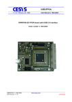
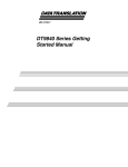
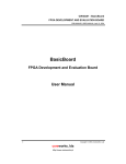
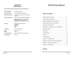
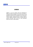
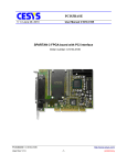
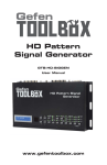
X2S_USB User Manual
Version
1.0
Date
November 23, 2001
Author
Manfred Kraus
Email
[email protected]
Updates
http://www.cesys.com
CESYS Gesellschaft für angewandte Mikroelektronik mbH
Buchenstrasse 13
D – 91074 Herzogenaurach
Germany
X2S_EVAL User Manual
-1-
Table of contents
1
OVERVIEW
4
1.1
Introduction
4
1.2
Features
4
1.3
FPGA Design Tools
4
1.4
Connector diagram
5
1.5
Available FPGAs in Standard Version
6
1.6
Description
6
1.7
USB-Interface
6
FPGA PIN USAGE
7
2.1
FPGA I/O Pins
7
2.2
Leds
7
2.3
Pinout Expansion Port J2 (14 pin)
7
2.4
Pinout Expansion Port CON2 (96 pin)
8
2.5
FPGA Clock signals
9
2.6
JTAG Interface
11
2.7
Power supply
11
2.8
Power Led
11
2.9
Undocumented connectors
12
2
3
USER PROGRAMMABLE CLOCK GENERATOR
13
4
TESTPOINTS
14
4.1
EZ-USB memory interface
15
4.2
Auxiliary EZ-USB – FPGA interface
16
4.3
Unused FPGA Pins
16
5
DOWNLOADING FPGA DESIGNS
17
5.1
Using file format EXO
17
5.2
Using file format RBT
17
5.3
Done Led
17
X2S_EVAL User Manual
-2-
5.4
Resetting FPGA Designs
17
6
DATA PATH FPGA - PC
18
7
SAMPLE DESIGNS
21
7.1
Global design hints
Dont use asynchronous logic
Synchronize external signals
Always drive input pins
Double-check the pinout
21
21
21
22
22
7.2
Led Flasher
23
7.3
“Reading and Writing data” Sample Design
24
7.4
Data streaming Sample Design
26
WHERE TO GET INFORMATION
29
8
8.1
Newsgroups
29
8.2
Links
29
8.3
Books
29
X2S_EVAL User Manual
-3-
1 Overview
1.1
Introduction
The X2S_USB FPGA board is suited for the following applications:
é
é
é
é
1.2
é
é
é
é
é
é
é
é
é
é
é
1.3
Design Demonstration
Training and Education
Rapid Prototyping
Production
Features
XILINX XC2S200-5PQ208C FPGA
USB 1.1 compliant device (Plug-and-Play)
selectable self-powered or bus-powered
user programmable clock source 1 MHz – 100 MHz
Two expansion ports (96 pins and 14 pins)
4 Leds
all FPGA pins routed to test connectors
JTAG interface (TMS, TDI, TDO,TCK, GND, VCC)
Driver for WIN98 / WIN 2000 included
Sample code (Sourcecode) and test-program included
schematics included
FPGA Design Tools
To simulate and synthesize your FPGA design you need appropriate tools.
Xilinx offers a toolset called “ISE WebPack 4.1” free of charge on their website:
http://www.xilinx.com/webpack/index.html . The ISE WebPack fully supports the
XC2S200 Spartan-II FPGA. There are also other commercial tools available from
Xilinx and various other vendors.
X2S_EVAL User Manual
-4-
1.4
Connector diagram
X2S_EVAL User Manual
-5-
1.5
Available FPGAs in Standard Version
The X2S_USB development board is available with the following SPARTAN-II
FPGA: XC2S200-5PQ208C
Device
Logic
Cells
XC2S200
5,292
1.6
Typical System
CLB
Gate Range
array
(Logic and RAM)
71,000 –
28x42
200,000
Total
CLBs
1,176
Total Block
Ram
Blocks
14
Total
Block
RAM Bits
57,344
Description
X2S_USB is a development platform for designs with Xilinx SPARTAN II FPGAs.
A 96-pin VG connectors allows the attachment of external hardware to the FPGA.
The board is equipped with a XC2S200-5PQ208C XILINX FPGA, a member of the
Spartan II family. This programmable logic device receives its internal functions after
it has been configured by downloading a bit-stream that represents the design. The
change of logic functions is possible at any time without the need of a deviceprogrammer.
When the USB interface of the X2S_USB board is connected to a PC, the FPGA
may be loaded with the desired configuration. The software that comes with the
board permits to load new configurations anytime.
An jumper-programmable clock oscillator supplies a basic clock that can be used by
the FPGA. This clock can be further multiplied or divided by the DLL inside the
FPGA.
The 96-pin VG expansion connector of the X2S_USB allows connections to I/O pins
of the FPGA as well as to 3.3 V and GND. Many extensions can be attached directly
without the need of an additional external power supply. In addition an on-board 14pin connector can be used for further extensions.
1.7
USB-Interface
The USB interface of the board is implemented using an additional device – the
CYPRESS EZUSB. FPGA designs do not need to include USB specific code.
Developers do not need to know the details of the USB bus. To enable
communication between the FPGA and a user program running on the PC, the
memory interface of the EZUSB device is used.
If your design works “stand-alone” and does not require any communication with the
PC, you may ignore the USB interface details and use it only for downloading your
design.
X2S_EVAL User Manual
-6-
2 FPGA pin usage
2.1
FPGA I/O Pins
All FPGA I/O Pins use the I/O Standard LVTTL (3,3 Volt) but they accept 5 Volt
Input signals without the need of level shifters or series resistors. Because the
VCCO inputs of all banks are tied together in the PQ208 package, they are
hardwired to 3,3 Volt on the X2S_USB.
2.2
Leds
LEDs
Led 0
Led 1
Led 2
Led 3
FPGA I/O
FPGA I/O
FPGA I/O
FPGA I/O
Pin 102
Pin 101
Pin 100
Pin 99
The Leds light up when there is a low level at the corresponding FPGA Pin. The
meaning of the LEDs is defined by the user’s FPGA design.
2.3
Pinout Expansion Port J2 (14 pin)
J2
14-pin expansion connector
Pin 1
3.3 Volt
Pin 3
FPGA I/O Pin 98
Pin 5
FPGA I/O Pin 96
Pin 7
FPGA I/O Pin 94
Pin 9
FPGA I/O Pin 89
Pin 11
FPGA I/O Pin 87
Pin 13
GND
Pin 2
Pin 4
Pin 6
Pin 8
Pin 10
Pin 12
Pin 14
3.3 Volt
FPGA I/O Pin 97
FPGA I/O Pin 95
FPGA I/O Pin 90
FPGA I/O Pin 88
FPGA I/O Pin 86
GND
This expansion connector can be used to interface to electronics on a separate
board.
Another usage is to connect a logic analyser for debugging purposes.
X2S_EVAL User Manual
-7-
2.4
Pinout Expansion Port CON2 (96 pin)
The 96-pin VG external expansion connector is of type “female”. Please use the
connector diagram to indicate pin 1. On some connectors, the numbers are printed
upside down.
Each individual pin of the FPGA can be configured as input, output, or bi-directional.
Make sure your FPGA design does not drive pins that should be an input and are
already driven by external connected logic. This is also important for bi-directional
signals.
CON 2
Pin
1
2
3
4
5
6
7
8
9
10
11
12
13
14
15
16
17
18
19
20
21
22
23
24
25
26
27
28
29
30
31
32
96-pin VG Expansion connector
A
B
3.3 Volt
3.3 Volt
FPGA I/O Pin 84
FPGA I/O Pin 83
FPGA I/O Pin 81
FPGA I/O Pin 75
FPGA I/O Pin 73
FPGA I/O Pin 71
FPGA I/O Pin 69
FPGA I/O Pin 68
FPGA I/O Pin 63
FPGA I/O Pin 62
FPGA I/O Pin 60
FPGA I/O Pin 59
FPGA I/O Pin 57
FPGA I/O Pin 49
FPGA I/O Pin 47
FPGA I/O Pin 46
FPGA I/O Pin 44
FPGA I/O Pin 43
FPGA I/O Pin 41
FPGA I/O Pin 37
FPGA I/O Pin 35
FPGA I/O Pin 34
FPGA I/O Pin 31
FPGA I/O Pin 30
FPGA I/O Pin 27
FPGA I/O Pin 24
FPGA I/O Pin 22
FPGA I/O Pin 21
FPGA I/O Pin 18
FPGA I/O Pin 17
FPGA I/O Pin 15
FPGA I/O Pin 14
FPGA I/O Pin 9
FPGA I/O Pin 8
FPGA I/O Pin 6
FPGA I/O Pin 5
FPGA I/O Pin 3
FPGA I/O Pin 206
FPGA I/O Pin 204
FPGA I/O Pin 203
FPGA I/O Pin 201
FPGA I/O Pin 200
FPGA I/O Pin 195
FPGA I/O Pin 194
FPGA I/O Pin 192
FPGA I/O Pin 191
FPGA I/O Pin 188
FPGA I/O Pin 187
FPGA I/O Pin 180
FPGA I/O Pin 179
FPGA I/O Pin 176
FPGA I/O Pin 175
FPGA I/O Pin 173
FPGA I/O Pin 172
FPGA I/O Pin 168
FPGA I/O Pin 167
FPGA I/O Pin 166
FPGA I/O Pin 165
FPGA I/O Pin 164
FPGA I/O Pin 162
GND
GND
X2S_EVAL User Manual
-8-
C
3.3 Volt
FPGA I/O Pin 82
FPGA I/O Pin 74
FPGA I/O Pin 70
FPGA I/O Pin 67
FPGA I/O Pin 61
FPGA I/O Pin 58
FPGA I/O Pin 48
FPGA I/O Pin 45
FPGA I/O Pin 42
FPGA I/O Pin 36
FPGA I/O Pin 33
FPGA I/O Pin 29
FPGA I/O Pin 23
FPGA I/O Pin 20
FPGA I/O Pin 16
FPGA I/O Pin 10
FPGA I/O Pin 7
FPGA I/O Pin 4
FPGA I/O Pin 205
FPGA I/O Pin 202
FPGA I/O Pin 199
FPGA I/O Pin 193
FPGA I/O Pin 189
FPGA I/O Pin 181
FPGA I/O Pin 178
FPGA I/O Pin 174
EXT_CLK1 Input
EXT_CLK2 Input
OSC_24 Output
SYSCLK Output
GND
External clocks
EXT_CLK1 and EXT_CLK2 may be routed to the FPGA’s dedicated clock input pins
(see description of Jumper matrix J4 and J5 below). Using this two signals, a user
provided clock may be used with the FPGA’s global clock buffers. This pins are
inputs to the X2S_USB board.
OSC_24 clock signal
The OSC_24 clock signal is used by the USB controller. All signals that are involved
in reading and writing data between USB and the FPGA are synchronous to this
clock. Designs that use this clock signal dont have to care about synchronizing USB
data to their clock domains. This pin is an output of the X2S_USB board.
SYSCLK clock signal
The frequency of the SYSCLK clock signal can be adjusted by the user (see the
description of the SYSCLK oszillator below). This pin is an output of the X2S_USB
board.
2.5
FPGA Clock signals
FPGA clock signals
OSC_24
GCK1 source selectable by Jumper J4
GCK2 source selectable by Jumper J5
SYSCLK
FPGA I/GCK0
FPGA I/GCK1
FPGA I/GCK2
FPGA I/GCK3
Pin 80
Pin 77
Pin 182
Pin 185
There are 4 clock sources on the X2S_USB evaluation board. No matter which of
them you use as the main clock for your design, you should synchronize all
incoming asynchronous signals to it with a FlipFlop before using them internally. If
you fail to do so, your design may work sometimes but not every time. One-hot state
machines might lose their “hot”-state and become inoperable. Encoded state
machines might enter wrong or illegal states.
OSC_24
This is the clock, the USB controler EZ-USB uses. If you want to transmit or receive
data using the USB interface, it is the easiest way to choose this clock as main clock
for your design. The FPGA looks like external memory to the EZ-USB and all
involved signals (Read, Write, Chipselect, ...) are synchronous to the EZ-USB’s
clock.
GCK1 / GCK2
The source of GCK1 may be FRD_N, FWR_N, WR_N or EXT_CLK1.
J4 GCK1 clock source
Pin 1 – 2 closed
Pin 3 – 4 closed
Pin 5 – 6 closed
Pin 7 – 8 closed
X2S_EVAL User Manual
FRD_N
FWR_N
WR_N
EXT_CLK1
-9-
The source of GCK2 may be FRD_N, FWR_N, RD_N or EXT_CLK2.
J5 GCK2 clock source
Pin 1 – 2 closed
Pin 3 – 4 closed
Pin 5 – 6 closed
Pin 7 – 8 closed
FRD_N
FWR_N
RD_N
EXT_CLK2
FRD_N and FWR_N are used by the EZ-USB when streaming data between the
FPGA and the USB interface using single cycle transfers without an address phase
(see EZ-USB datasheet).
WR_N and RD_N are used by the EZ-USB when accessing addressable registers of
the FPGA design. See “Reading and writing data” sample design for details.
EXT_CLK1 and EXT_CLK2 may be sourced by external electronics connected to
expansion port 1.
X2S_EVAL User Manual
- 10 -
2.6
JTAG Interface
CON 3
Pin 1
Pin 2
Pin 3
Pin 4
Pin 5
Pin 6
Pin 7
JTAG connector
+3.3 Volts
GND
n.c.
TMS
TCK
TDI
TDO
The JTAG connector can be used together with an “Xilinx download cable” or to
access the boundary-scan chain of the SPARTAN II devices. For downloading a
design you do not need to use the JTAG interface because the FPGA can be
configured via the USB interface.
2.7
Power supply
The X2S_USB board can be configured to be self powered or bus powered.
J1
Power source select
Pin 1 – 2
Pin 2 – 3
self powered
bus powered
The default setting is “bus powered”. The power is provided by the USB bus.
If the X2S_USB is the only device on the USB bus, most computers should allow a
maximum current of 400mA (2 Watt). This may not be true for notebooks.
The option “self powered” requires an external power supply on SK1. Use this
method if your design draws more current than your USB bus can deliver.
SK1
Pin 1
Pin 2
External Power connector
GND
+ 5 Volt
Caution: Be careful when using the external power connector. If you apply more
than 5,5 Volts or if you reverse the polarity, the board will permanently fail and may
not be reparable. If you connect an external power supply to SK1 watch Led 4. If it
does not light up immediately after applying power, there is something wrong and
you should switch off the power supply immediately.
2.8
Power Led
Led 4 will light when the board is powered up.
X2S_EVAL User Manual
- 11 -
2.9
Undocumented connectors
Any undocumented connectors are for production tests only. Please dont use them
for any purpose.
X2S_EVAL User Manual
- 12 -
3 User Programmable clock generator
The SYSCLK oscillator may be programmed to any desired frequency between 1
MHz and 100 MHz by setting Jumpers on J6, J7 and J8. Refer to the ICS525-02
datasheet for details.
To determine the Jumper positions for a given frequency you may use the online
ICS525 calculator at www.icst.com/products/ics525inputForm.html.
The input frequency is 12 MHz. VDD is 3.3 Volt.
Figure 1
Jumper J6, J7 and J8 Layout.
The following tables show examples for common settings.
Important: The value 0 means set the jumper, 1 means leave the jumper position
empty.
Frequency
[MHz]
14,31818
24,00000
40,00000
60,00000
100,0000
S
2
0
0
0
0
1
S
1
1
1
0
0
1
S
0
1
0
1
1
0
R
6
0
0
0
0
0
R
5
1
0
0
0
0
R
4
0
0
0
0
0
R
3
1
0
0
0
0
R
2
0
0
1
0
1
R
1
1
0
0
0
0
R
0
0
1
0
1
0
V
8
0
0
0
0
0
V
7
0
0
0
0
0
V
6
1
0
0
0
0
V
5
1
0
0
0
0
V
4
0
1
0
0
1
V
3
0
0
1
0
0
V
2
0
0
1
1
0
V
1
0
0
0
1
0
Designs, that need to be clocked faster than 40 MHz should use the SPARTAN-II
DLLs to double the input clock frequency.
X2S_EVAL User Manual
- 13 -
V
0
1
0
0
1
1
4 Testpoints
All FPGA pins are routed to testpoints to ease the connection of measurement
equipment like Logic Analyzers. The figure below shows the relationship between
FPGA pins and Testpoints.
Orientation: Please notice the marker (no pin opposite to P160) in the lower left
corner .
101
102
106
108
110
112
114
119
121
123
126
129
133
134
136
139
141
146
148
150
152
154
99
100
97
98
95
96
90
94
88
89
86
87
104
107
109
111
113
115
120
122
125
127
132
135
138
140
142
147
149
151
153
155
81
82
80
75
74
73
71
70
69
68
67
63
62
61
60
59
58
57
49
47
45
42
41
36
34
31
29
23
21
18
16
14
9
7
5
3
XC2S200
FPGA
O
--160
Figure 2
83
84
162
161
163
164
165
166
167
168
172
173
174
175
176
178
179
180
181
185
187
188
189
191
193
192
195
194
200
199
202
201
204
203
48
46
44
43
37
35
33
30
27
24
22
20
17
15
10
8
6
4
206
205
FPGA Pin numbers of testpoints.
Around the testpoints, there are many single pins connected to GND. Theese pins
are marked with the letter X in the connector diagram.
X2S_EVAL User Manual
- 14 -
4.1
EZ-USB memory interface
EZ-USB memory interface
Address A0
Address A1
Address A2
Address A3
Address A4
Address A5
Address A6
Address A7
Address A13
Address A14
Address A15
Data/Address PAD0
Data/Address PAD1
Data/Address PAD2
Data/Address PAD3
Data/Address PAD4
Data/Address PAD5
Data/Address PAD6
Data/Address PAD7
OE_N
RD_N
CS_N
WR_N
FPGA I/O
FPGA I/O
FPGA I/O
FPGA I/O
FPGA I/O
FPGA I/O
FPGA I/O
FPGA I/O
FPGA I/O
FPGA I/O
FPGA I/O
FPGA I/O
FPGA I/O
FPGA I/O
FPGA I/O
FPGA I/O
FPGA I/O
FPGA I/O
FPGA I/O
FPGA I/O
FPGA I/O
FPGA I/O
FPGA I/O
Pin 152
Pin 151
Pin 150
Pin 149
Pin 148
Pin 147
Pin 146
Pin 142
Pin 141
Pin 140
Pin 139
Pin 115
Pin 114
Pin 113
Pin 112
Pin 111
Pin 110
Pin 109
Pin 108
Pin 120
Pin 119 and 182 (see J5)
Pin 160
Pin 77 (see J4)
The EZ-USB memory interface can be used to implement data communication
between the USB controller and the FPGA.
All signals are synchronous to the EZ-USB clock OSC_24.
See chapter “Data path FPGA – PC” for details.
X2S_EVAL User Manual
- 15 -
4.2
Auxiliary EZ-USB – FPGA interface
To provide an quick and easy way to access the state of some FPGA Pins directly
on the PC, the auxiliary EZ-USB FPGA interface may be used. There are 11 signals
(L0 to L10) that provide a connction between the EZ-USB controller and FPGA I/O
Pins. The software that comes with the XC2S_USB board allows each of this signals
to be configured as input or output of the EZ-USB. You can switch the state of the
output pins by a simple mouse-cIick. You also see the state of the input pins. This
interface is something like “remote” LEDs and switches. See the software
description for details.
The auxiliary interface is especially usefull if you do not want to write your own PC
software, but you need limited communication with your FPGA design.
Caution: Please do not configure any of the L10..L0 signals as an output if your
FPGA design already drives this signal.
Auxiliary EZ-USB – FPGA interface pinout
Signal L0
FPGA I/O
Signal L1
FPGA I/O
Signal L2
FPGA I/O
Signal L3
FPGA I/O
Signal L4
FPGA I/O
Signal L5
FPGA I/O
Signal L6
FPGA I/O
Signal L7
FPGA I/O
Signal L8
FPGA I/O
Signal L9 (synchronize fast read)
FPGA I/O
Signal L10 (synchronize fast write)
FPGA I/O
Signal L11 (FPGA Design Reset)
FPGA I/O
Pin 138
Pin 136
Pin 135
Pin 134
Pin 133
Pin 132
Pin 129
Pin 127
Pin 126
Pin 125
Pin 123
Pin 122
The signal L11 is always driven by the EZ-USB controller. In your design you can
use it as an input that resets the design when it is high. See chapter “Resetting
FPGA Designs” for details.
Caution: Never use Pin 122 as an output in your FPGA design.
The signals L9 and L10 are read by the USB firmware. They provide a way to
synchronize data flow when implementing isochronous data transfers.
See chapter “Data streaming Sample Design” for details.
Signals L0..L8 can be used freely by the user’s designs.
4.3
Unused FPGA Pins
These pins may be accessed via their associated test points. They are not routet to
any other target: FPGA I/O Pin 121, FPGA I/O Pin 163, FPGA I/O Pin 161
X2S_EVAL User Manual
- 16 -
5 Downloading FPGA designs
5.1
Using file format EXO
Before downloading a design, it must be converted to the EXORmacs format using
the Xilinx “Prom File Formatter” tool. Choose Type: “byte-wide” and “single Prom”.
The resulting *.EXO file can be downloaded to the X2S_USB evaluation board via
USB interface. See the description of XC2USB_DIAG.EXE for details.
5.2
Using file format RBT
The Xilinx FPGA tools do not generate a rawbit “RBT” file by default. There is an
option, that must be checked to generate this file.
Open Xilinx ISE Project Navigator and load your design.
Right-click on “Generate Programming File” and select “Properties”
Make sure the box “Create ASCII configuration file” is checked.
Click “OK”.
Important: If design changes are not reflected in the “real world” check if the option
to generate an RBT file is checked. If not you are downloading the same old RBT file
even if your input design has changed.
5.3
Done Led
When the “DONE” pin of the FPGA is high, LED 5 will light up. This indicates that
the FPGA has been configured successfully.
5.4
Resetting FPGA Designs
Signal L11 (FPGA I/O Pin 122) can be used as a Reset signal in customer designs.
While downloading an FPGA configuration bitstream L11 is held high. When
configuration is done, L11 is made low.
It is possible to switch L11 high or low any time after download to re-initialize the
design.
In most cases you need to synchronize L11 to the FPGA clock. If you fail to do so,
“one-hot” state machines may loose their hot bit or counters may count wrong on the
first clock edge after Reset.
X2S_EVAL User Manual
- 17 -
6 Data path FPGA - PC
The external memory interface of the EZ-USB chip can be used to transmit data
between the FPGA and the PC. The meaning and timing of the signals is
documented in the data sheet of the EZ-USB chip.
Figure 3
EZ-USB Memory Read sequence
X2S_EVAL User Manual
- 18 -
Figure 4
EZ-USB Memory Write sequence
Figure 5
EZ-USB Fast-Read sequence
X2S_EVAL User Manual
- 19 -
Figure 6
EZ-USB Fast Write Read sequence
X2S_EVAL User Manual
- 20 -
7 Sample Designs
The sample designs can be found on the CD-ROM that comes with the X2S_USB
board. Some of them have been synthesized using Xilinx WebPack.
Use “File->Open Project” to load them. If you work with another design system, you
will use only the VHDL files and the UCF files of the samples. The files with the
extension “UCF” are needed to constrain the I/O Pins to their correct locations. You
can also load the precompiled samples without recompiling them to check their
functionality.
See “Sample Designs Tutorial” for details.
7.1
Global design hints
Although this document is not an introduction to FPGA design technics there are a
few pitfalls that are awful enough to stress you for days.
•
Dont use asynchronous logic
Here is one example how asynchronous logic can make your design fail: If you use
the output of an comparator as the clock signal of a FlipFlop, every short needle that
comes out of the comparator will clock the FlipFlop. You cannot put an capacitor on
the output of the comparator as you would try in “real life” hardware. And most
probably the design will work as long as you test it, but will fail if you send it out to
the customer.
The solution is to convert the design to synchronous logic. Source all FlipFlops with
a global clock and use the output of the comparator as “clock enable” of the targetFlipFlop. This way signals inside the FPGA will change state only on (rising) clock
edges of the global clock. The time between two consecutive clock edges will allow
the signals to travel from the Q outputs of the FlipFlops through combinatorial logic
to the D inputs of the target FlipFlops.
In practice, there are almost no reasons to use asynchronous logic.
•
Synchronize external signals
If you use external signals that may change levels at any time, it is neccessary to
synchronize them first. State machines, for example, that jump to different states
depending on unsynchronized external signals may jump to undefined states or
loose their one-hot bit.
The easiest way to synchronize external signals is to use an INFF and clock it with
the global system clock. A more detailed analysis of the problem shows that
sometimes more than one FlipFlop is needed to synchronize external signals due to
metastability issues that become relevant at high clock frequenzies. In most cases
one single FlipFlop will do the job.
X2S_EVAL User Manual
- 21 -
•
Always drive input pins
Input pins, that are left floating may cause trouble - even if their state (high or low) is
not relevant to the design. This is especially a problem with external buses that have
more than one driver. If no driver is active, the signal is undefined and may float to
an voltage between high and low. It is a good idea to use pullup, pulldown or weakkeeper in this situation.
•
Double-check the pinout
If you use an FPGA I/O Pin as an output and it is also driven from another source, a
lot of current may flow and destroy the pins output driver.
Pins without any location constraints are placed by the FPGA design tool at arbitrary
locations.
X2S_EVAL User Manual
- 22 -
7.2
Led Flasher
This simple design implements a 24 bit counter. The 4 most significant bits are
connected to the 4 LEDs. They will flicker as long as the counter is running.
The name of the design is “LEDFLASHER.VHD”. The pinout constraints are stored
in the file “LEDFLASHER.UCF”. This design was tested using XILINX WebPACK.
-- ------------------------------------------------- Demonstration Example: LEDFLASHER.VHD
--- Use with pinouts defined in "ledflasher.ucf"
-- to run on XC2S_USB FPGA board
--- (C) CESYS GmbH, 2001 Manfred Kraus
-- -----------------------------------------------library IEEE;
use IEEE.std_logic_1164.all;
use IEEE.std_logic_unsigned.all;
-- with this lib we can use <counter + 1>
-- instead of <counter + "000000000000000001">
entity LEDFLASH
port (
P_SCLK:
P_LED1:
P_LED2:
P_LED3:
P_LED0:
);
end LEDFLASH;
is
in STD_LOGIC;
out STD_LOGIC;
out STD_LOGIC;
out STD_LOGIC;
out STD_LOGIC
architecture LEDFLASH_arch of LEDFLASH is
signal counter: STD_LOGIC_VECTOR (23 downto 0);
begin
P_LED3
P_LED2
P_LED1
P_LED0
<=
<=
<=
<=
counter
counter
counter
counter
(23);
(22);
(21);
(20);
process (P_SCLK)
begin
if (P_SCLK = ’1’ AND P_SCLK’EVENT) then
counter <= counter + 1;
end if;
end process;
end LEDFLASH_arch;
X2S_EVAL User Manual
- 23 -
7.3
“Reading and Writing data” Sample Design
The dataio.vhd sample shows how to implement registers in your FPGA that can be
accessed from the PC.
After you have configured the FPGA with this design using “XC2USB_DIAG.EXE”
you can test it. Write two numbers A and B to address 0 and 1 of Block 0 by typing
the command: write 0 0 75 25
If you dump the memory space, you will see the results 75hex – 25hex = 50hex
and 75hex + 25hex = 9Ahex
To dump the memory space you may use the command: readb 0
------------------------------------------------------ DATAIO.VHD
--- this sample demonstrates how to implement
-- read / write registers in an FPGA.
-- They can be accesses from the EZUSB controler.
--- address
Write
Read
-- base + 0
Operand A
A + B
-- base + 1
Operand B
A - B
---- (C) CESYS GmbH 2001, M. Kraus
----------------------------------------------------library IEEE;
use IEEE.std_logic_1164.all;
use IEEE.NUMERIC_STD.all;
use IEEE.std_logic_arith.all;
use IEEE.std_logic_unsigned.all;
entity Dataio is
port (
P_OE_N: in STD_LOGIC;
P_WR_N: in STD_LOGIC;
P_Address: in STD_LOGIC_VECTOR (7 downto 0);
P_Data: inout STD_LOGIC_VECTOR (7 downto 0)
);
end Dataio;
architecture Dataio_arch of Dataio is
signal SEL: STD_LOGIC_VECTOR ( 1 downto 0);
signal Data: STD_LOGIC_VECTOR ( 7 downto 0);
signal Memory0: STD_LOGIC_VECTOR ( 7 downto 0);
signal Memory1: STD_LOGIC_VECTOR ( 7 downto 0);
X2S_EVAL User Manual
- 24 -
begin
AdressSelector: process (P_Address, Memory0, Memory1)
begin
case P_Address is
when "00000000" =>
SEL <= "01";
Data <= Memory0 + Memory1;
when "00000001" =>
SEL<= "10";
Data <= Memory0 - Memory1;
when others =>
SEL<= "00";
Data <= "00000000";
end case;
end process;
WriteProcess: process (P_WR_N, SEL)
begin
if (P_WR_N = ’1’ and P_WR_N’EVENT) then
if (SEL(0) = ’1’) then
Memory0 <= P_Data;
end if;
if (SEL(1) = ’1’) then
Memory1 <= P_Data;
end if;
end if;
end process;
ReadProcess: process (P_OE_N, Data)
begin
if (P_OE_N = ’1’) then
P_Data <= "ZZZZZZZZ";
else
P_Data <= Data;
end if;
end process;
end Dataio_arch;
X2S_EVAL User Manual
- 25 -
7.4
Data streaming Sample Design
The file “fifotst.vhd” shows how to transport data from the PC to the FPGA and vice
versa using the EZUSB “fast_write” and “fast_read” mechanisms. The maximum
sustained data rate that can be achieved is between 800 and 900 kByte/s.
This simple design only buffers the incoming data in a FIFO and sends it back to the
USB controller. The FIFO is implemented using the XILINX CoreGen tool. The
design was created and synthesized using XILINX Foundation.
To synchronize the data flow, two signals (L9 and L10) must be implemented by the
FPGA. These signals are used by the USB controller to determine if there is a block
of data available (from the FPGA) and if data can be sent to the FPGA.
If L9 is low, the USB controller may start reading data from the FPGA. The amount
of data that will be red may be any number up to a maximum of 511 bytes. In other
words: The FPGA should make L9 low when there are 511 bytes or more available.
If L10 is low, the USB controller is allowed to write a block of data to the FPGA using
the FRD signal. The size of the block may be any value up to a maximum of 511
bytes.
library IEEE;
use IEEE.std_logic_1164.all;
entity fifotest is
port (
P_SCLK_x: IN std_logic;
P_data: INOUT std_logic_VECTOR(7 downto 0);
P_fwr_x: IN std_logic;
P_frd_x: IN std_logic;
P_L11: IN std_logic;
-- Reset
P_L10: OUT std_logic;
-- low: FPGA can eat 511 bytes of data
P_L9: OUT std_logic;
-- low: FPGA can give 511 bytes of data
P_led0: OUT std_logic;
P_led1: OUT std_logic;
P_led2: OUT std_logic;
P_led3: OUT std_logic
);
end fifotest;
-- synopsys translate_off
Library XilinxCoreLib;
-- synopsys translate_on
configuration cfg_fifotest of fifotest is
for fifotest_arch
-- synopsys translate_off
for all : fifo1023 use entity
XilinxCoreLib.async_fifo_v3_0(behavioral)
generic map(
c_wr_err_low => 0,
c_has_rd_count => 0,
c_has_rd_ack => 0,
c_wr_ack_low => 0,
c_has_wr_count => 1,
c_has_wr_ack => 0,
X2S_EVAL User Manual
- 26 -
c_has_almost_full => 0,
c_has_almost_empty => 0,
c_wr_count_width => 2,
c_rd_count_width => 2,
c_has_rd_err => 0,
c_data_width => 8,
c_has_wr_err => 0,
c_rd_ack_low => 0,
c_rd_err_low => 0,
c_fifo_depth => 1023,
c_enable_rlocs => 0,
c_use_blockmem => 1);
end for;
-- synopsys translate_on
end for;
end cfg_fifotest;
architecture fifotest_arch of fifotest is
component fifo1023
port (
din: IN std_logic_VECTOR(7 downto 0);
wr_en: IN std_logic;
wr_clk: IN std_logic;
rd_en: IN std_logic;
rd_clk: IN std_logic;
ainit: IN std_logic;
dout: OUT std_logic_VECTOR(7 downto 0);
full: OUT std_logic;
empty: OUT std_logic;
wr_count: OUT std_logic_VECTOR(1 downto 0));
end component;
component BUFGP
port (I: in std_logic; O: out std_logic);
end component;
signal
signal
signal
signal
signal
signal
signal
signal
signal
signal
signal
wr_count: std_logic_VECTOR(1 downto 0);
outdata: std_logic_VECTOR(7 downto 0);
P_SCLK: std_logic;
P_frd: std_logic;
P_fwr: std_logic;
FRD: std_logic;
FWR: std_logic;
LED0: std_logic;
LED1: std_logic;
L10: std_logic;
L9: std_logic;
begin
P_LED0
P_LED1
P_LED2
P_LED3
<=
<=
<=
<=
LED0 xor ’1’;
LED1 xor ’1’;
L10;
L9;
P_L9 <= L9;
P_L10 <= L10;
FRD <= P_frd xor ’1’;
X2S_EVAL User Manual
- 27 -
FWR <= P_fwr xor ’1’;
u1: fifo1023
port map (
din => P_data,
wr_en => FWR,
wr_clk => P_SCLK,
rd_en => FRD,
rd_clk => P_SCLK,
ainit => P_L11,
dout => outdata,
full => LED0,
empty => LED1,
wr_count => wr_count);
u2:
u3:
u4:
BUFGP port map (I => P_SCLK_x, O => P_SCLK);
BUFGP port map (I => P_fwr_x, O => P_fwr);
BUFGP port map (I => P_frd_x, O => P_frd);
process (outdata, P_frd)
begin
if (FRD = ’1’) then
P_data <= outdata;
else
P_data <= "ZZZZZZZZ";
end if;
end process;
process (wr_count)
begin
if (wr_count(1) = ’1’) then
L9 <= ’0’;
else
L9 <= ’1’;
end if;
end process;
process (wr_count)
begin
if (wr_count(1) = ’0’) then
L10 <= ’0’; -- FPGA can eat data
else
L10 <= ’1’;
end if;
end process;
end fifotest_arch;
X2S_EVAL User Manual
- 28 -
8 Where to get information
8.1
Newsgroups
There are two newsgroups that discuss FPGA and VHDL related themes:
comp.arch.fpga and comp.lang.vhdl
8.2
Links
The list of links on the CESYS homepage www.cesys.com may also be usefull.
8.3
Books
“VHDL Design, Representation and Synthesis”
James R.Armstrong, F.Gail Gray
Prentice Hall, ISBN 0-13-021670-4
X2S_EVAL User Manual
- 29 -