1
Section 24
CREATING A FOUNDATION FIELDBUS
STRATEGY BY USING THE DF100
Introduction
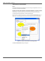
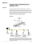
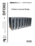
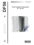
This section describes the fieldbus strategy configuration by using the DF100 controller. The figure
below shows a ball mill (rotary) whose product temperature must be monitored.
PROJ_DF100
Figure 24. 1 - Example of temperature monitoring in a ball mill
The purpose is to monitor the product temperature at the center of the ball mill. The product
temperature is measured by two wireless temperature transmitters installed in the hull of the mill, in
its central part, in diametrically opposite positions. Measured temperatures will be transmitted from
each of the temperature transmitters to the DF100 (WirelessHART Gateway) via WirelessHART
communication. In the DF100, positioned near the ball mill and connected to the HSE network
control, there will be special transducer blocks that will map the temperatures received from the
transmitters. In addition to the transducers, the DF100 has function blocks that are used to calculate
the average temperature of the mill from the two measured temperatures.
24.1
DFI302 – User’s Manual – AUG/14 - K
Starting an Area
Step 1
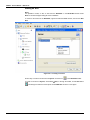
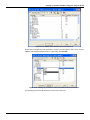
It is possible to create, or edit, an area from the Studio302. In the Studio302 interface select
Areas. A window will appear listing all areas of database.
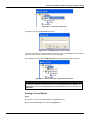
To create a new area from the Studio302, right-click inside the Areas window, then choose New
Area.
Figure 24. 2 - Creating a new area
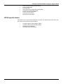
Another way to create a new area is from Syscon. Click the icon
in the Studio302 toolbar.
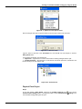
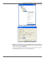
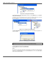
To create a new area on Syscon, choose File New, or through the toolbar, choose New button
. The dialog box shows the areas options. Select HSE Area as shown in next figure:
24.2
Creating a Foundation Fieldbus strategy by using the DF100
Figure 24. 3 - Options to create Syscon areas
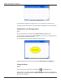
After choosing the area type, it opens a window to the user give a name to the new area.
Figure 24. 4 - New area name
Type the name for the area in the Area Name box, and click Ok. For this example, it chooses
PROJ_DF100 name.
A new window will appear. This window has:
Application – Logical Plant. To insert control and/or monitoring strategies into this part.
Fieldbus Networks – Physical Plant. To add devices and blocks (resources, transducers and
function blocks) to the area into this part.
Figure 24. 5 - Area divisions
Physical Plant Project
Step 2
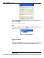
In the main window, PROJ_DF100, right-click the Fieldbus Networks icon,
, and choose
Communication Settings option, or through the toolbar, choose CommunicationSettings. The
communication settings dialog box will open.
24.3
DFI302 – User’s Manual – AUG/14 - K
Figure 24. 6 - Choosing the Server
Confirm if the Smar.HSEOLEServer.0 option has already been selected. Otherwise, the user must
select it, and then click OK.
Arranging the Fieldbus windows
Step 3
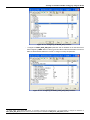
After selecting the Server for the area, click the sign placed at left of the New Fieldbus. The HSE
network will appear with a tag, for example, HSE Network 1*. Right-click this item and choose
Expand option. The figure below shows the HSE network:
Figure 24. 7 - Creating an HSE network
To arrange the screen, click the area window. So, choose Window menu on the Syscon toolbar,
and then Tile option.
Adding the Controller
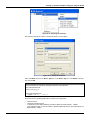
Step 4
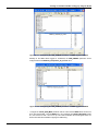
Right-clicking the HSE Network 2, it opens a dialog box to add new devices. Choosing New option,
it is possible to select devices such as Bridges, Controllers and Devices for the area. For the
aimed strategy, choose Controller option. Confirm this choice observing the following figure.
* This number changes if another area was created before. When a new HSE area is created, this
number increases.
24.4
Creating a Foundation Fieldbus strategy by using the DF100
Figure 24. 8 - Choosing the Controller
After selecting that option, it opens a window as shown in the next figure.
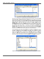
Figure 24. 9 - Setting the Controller
Select the DF100 device in the Device Type box. In the Device Tag box, enter DF100 or another
tag, and click OK.
IMPORTANT
Not all characters are valid when naming the elements, so pay attention;
The valid characters are:
A-Z a-z 0-9 # { } [ ] ( )+ The invalid characters are:
~`!@#$%^&*=|:;,.<>?/'"\
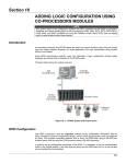
At this moment, the following blocks will be created in the configuration:
−
−
−
−
Resource block;
Diagnostic transducer block;
Transducer block for HART Gateway (Transducer Block for HART Gateway - TBHG);
One transducer block for the first HART or WirelessHART field device (Transducer Block for
WirelessHART - TBWH).
24.5
DFI302 – User’s Manual – AUG/14 - K
Figure 24. 10 – Blocks created after adding the controller
Quite simply, we understand that the DF100 (WirelessHART Gateway) and the WirelessHART and
1
HART field devices will be mapped on SYSTEM302 by the transducer blocks. This is possible due
to the HSE WIO technology, embedded in the DF100.
The DF100 will be mapped by the transducer block (single and mandatory) called Transducer Block
for HART Gateway (TBHG). Furthermore, each HART and WirelessHART field device will be
mapped by transducer blocks called Transducer Blocks for WirelessHART (TBWH). There will be as
many TBWH blocks as there are HART and WirelessHART field devices needed in the
configuration.
Adding HSE WIO Transducer and Function Blocks
Step 5
The first HSE WIO transducer block, TBHG, is automatically created when the DF100 controller was
added to the Physical Plant. Make sure that its MODE_BLK parameter is configured to Auto
(Automatic) before downloading the configuration on the DF100. This block, as monitored in Online
mode, shows the list of HART and/or WirelessHART field devices currently connected to the DF100.
Thus, we can understand that the TBHG provides to the system and to the user the Live List of field
devices connected to the DF100 via WirelessHART network. See Library B Function Blocks
Instruction Manual for additional information on the TBHG block.
The next step is to associate the TBWH block to the first wireless temperature transmitter of this
example. This TBWH was also automatically created (with the DF100-TBWH-1 tag) when the
2
DF100 controller was added. The transmitter Long Tag has to be attributed (suppose TI-400W-01 )
to the Block Tag of TBWH block. The following figures show the association between TBWH and
the transmitter.
1
2
The DF100 integrates HART, 4 to 20 mA conventional field devices, via WirelessHART adapters.
In online mode, the Long Tags of transmitters connected to DF100 can be found in the LIVE_LIST_TAG_x parameters of TBHG block.
24.6
Creating a Foundation Fieldbus strategy by using the DF100
Figure 24. 11 – Changing the attributes of TBWH block
Figure 24. 12 – Changing the attributes of TBWH block
Depending on the strategy, you can add as many TBWH blocks as there are HART and
WirelessHART field devices supported by the DF100 (see section Technical Specifications). For the
purposed example, just add another TBWH block, which will map the second temperature
transmitter. Its Long Tag will be TI-400W-02.
sign, near to the DF100 controller, and right-click
To add a new Function Block (FB), click the
the Virtual Field Device (HSE_FB_VFD) icon. Choose New Block option.
24.7
DFI302 – User’s Manual – AUG/14 - K
Figure 24. 13 – Adding New Blocks
The New Block dialog box will appear. In the Block Type option the blocks designed to the
controller can be selected.
Select the block in the Block Type box, and name it in the Block Tag box. Click OK. The following
figure shows adding the second TBWH block that will map the transmitter whose Long Tag is TI400W-02
Figure 24. 14 – Adding TBWH block
As a general rule, for each TBWH block added, it is recommended:
− Assign the Long Tag of the HART or WirelessHART field device to the block tag attribute of
TBWH.
− Configure the MODE_BLK parameter to Auto (Automatic) before downloading the configuration
on the DF100.
24.8
Creating a Foundation Fieldbus strategy by using the DF100
Figure 24. 15 – Configuring the MODE_BLK parameter
−
Configure the HART_EXPD_DEV_INFO parameter with the attributes of the field device that
will be mapped by TBWH. Refer to Library B Function Blocks Instruction Manual as well as the
3
HART or WirelessHART field device manual to configure correctly this parameter.
Figure 24. 16 – Configuring the HART_EXPD_DEV_INFO parameter
3
In online mode, if the desired field device is connected to DF100 and commissioned, it is recommended to configure the attributes of
HART_EXPD_DEV_INFO parameter with the values of the respective attributes of HART_ACTL_DEV_INFO parameter.
24.9
DFI302 – User’s Manual – AUG/14 - K
NOTE
The above parameterized attributes are specific to the considered field device - in this example the TT400 Smar
WirelessHART was used. Therefore, important to note that the values assigned to the attributes of HART_EXPD_DEV_INFO
parameter depend on the type of device (pressure, temperature, density, etc.) and its firmware version.
The table below summarizes the attributes values of the HART_EXPD_DEV_INFO parameter for some Smar WirelessHART
field devices:
Attribute
LD400WH
Firmware 3.0.1
TT400WH
Firmware 2.0.1
TT481WH
Firmware 1.0.0
HART_VERSION
7
7
7
7
NUM_OF_PROCESS_VARIABLES
11
4
12
18
HART_DD_REVISION
1
1
1
1
HART_DEVICE_REVISION
3
1
2
1
15882
15888
15881
15890
HART_MANUFACTURER_ID
62
62
62
62
HART_DISTRIBUTOR_ID
62
62
62
62
Unused
Unused
Unused
Unused
129
129
129
129
HART_DEVICE_TYPE
ANALOG_DISABLE
HART_DEVICE_PROFILE
24.10
DT400WH
Firmware 1.0.0
−
Knowing that the second temperature transmitter used in this example, whose tag is TI- 400W02, it is also a TT400 Smar WirelessHART with identical firmware to the TI-400W-01 transmitter,
configure the HART_EXPD_DEV_INFO parameter exactly as was done for the TBWH of TI- 01400W.
−
Configure the each one of the names that will be attributed to the HART_PV, HART_SV,
HART_TV, HART_QV, HART_5V, HART_6V, HART_7V, HART_8V and PRIMARY_VALUE
variables. These names have to be configured in the VAR_NAMES9 parameter. The names
(values) configured to the attributes (1) to (9) of this parameter refer to the names that will
identify in a single way (in the DF100 scope that has the TBWH) the HART_PV to
PRIMARY_VALUE variables, respectively. This procedure is necessary because the HSE WIO
input function blocks will use these names to address the HART variables values. The following
figure shows the parameterization of the VAR_NAME that will identify the HART_PV variable
provided by the TI-400W-01 transmitter. Important to note that, depending on the strategy, not
all VAR_NAMES need to be parameterized. See Library B Function Blocks Instruction Manual
for additional information on the TBWH transducer block, its parameters and parameterization.
Creating a Foundation Fieldbus strategy by using the DF100
Figure 24. 17 – Configuring the VAR_NAMES9 parameter of TBWH tagged TI-400W-01
Similarly for the TBWH block tagged as TI-400W-02, the VAR_NAMES9 parameter will be
configured with the TI-400W-02_Temperatura_do_moinho value.
Figure 24. 18 – Configuring the VAR_NAMES9 parameter of TBWH tagged TI-400W-02
−
Configure the LOCAL_MOD_MAP parameter with the value that the TBWH block should have
to be used with Modbus. The first TBWH has to be configured with LOCAL_MOD_MAP equals
to 0, the second one with 1 and so on up to 99. Refer to Modbus Protocol Support section for
further information about Modbus mapping and addressing.
24.11
DFI302 – User’s Manual – AUG/14 - K
Figure 24. 19 – Configuring the LOCAL_MOD_MAP parameter
From now on, we will add to the configuration HSE WIO input function blocks. In the DF100 the WIO
Analog Input (WAI) and Multiple Analog Input 16 (MAI16) blocks are available. These blocks are
variations of the HSE WIO for conventional Analog Input (AI) and Multiple Analog Input (MAI)
blocks, respectively. Despite having similar algorithms, the HSE WIO input function blocks have,
besides data types specifically designed for the HSE WIO technology, parameters named
CHANNEL_TAG. A HSE WIO input function block (such as WAI or MAI16) uses the
CHANNEL_TAG parameter instead of CHANNEL parameter to correctly address a HART variable,
from a TBWH transducer block. Knowing that, besides the already known parameterization steps for
the conventional input function blocks, it is necessary to parameterize the CHANNEL_TAG
parameters with HART variable names. In other words, the names parameterized for the
CHANNEL_TAG can be any names among those parameters parameterized in the VAR_NAMES9
parameters of the TBWH transducer blocks. Refer to the Function Blocks Manual for additional
information on the HSE WIO function blocks, its parameters and parameterization.
For the configuration of this example, add two WAI blocks. The addition of the WAI blocks is similar
to addition of TBWH block just described above. Each WAI block will address a wireless
temperature transmitter (and its data) via TBWH transducer block. For each WAI of the purposed
example, the CHANNEL_TAG is configured with the VAR_NAME assigned to the HART_PV
variable (see TBWH block parameterization above) of the addressed wireless temperature
transmitter. The two following figures demonstrate the CHANNEL_TAG configuration of the WAI
blocks that will address the temperature transmitters TI-400W-01 and TI-400W-02, respectively.
Figure 24. 20 – Configuring the CHANNEL_TAG that addresses the HART_PV of TI-400W-01
24.12
Creating a Foundation Fieldbus strategy by using the DF100
Figure 24. 21 – Configuring the CHANNEL_TAG that addresses the HART_PV of TI-400W-02
With the addition of the WAI blocks we have finished adding the HSE WIO transducers and function
blocks. See the figure below for having a general idea of HSE WIO blocks configured so far.
Figure 24. 22 – HSE WIO transducers and function blocks
Adding Conventional Function Blocks
Step 6
The user can also add others conventional function blocks, i.e., non-specific HSE WIO ones. For
that, in the New Block dialog box, select the desired function block in the Block Type box, and
then, in the Block Tag box, give a tag to the block. Click OK. The next figure shows the addition of
the ARTH function block (AR Block).
24.13
DFI302 – User’s Manual – AUG/14 - K
Figure 24. 23 –Adding a conventional function block
For this example, the ARTH block complements the strategy and it will be used in the DF100 to
calculate the average temperature in the ball mill.
NOTE
Only transducer and function blocks were added in the DF100 (WirelessHART Gateway). The
HART and WirelessHART field devices not support function blocks. They are only mapped in the
DF100 through TBWH transducer blocks.
The configuration with all the function and transducers blocks, conventional or not, is presented in
the following figure.
Figure 24. 24 – Complete wireless configuration
Now, the strategy area can be developed (Application, Logic Plant). First is necessary to create a
new Process Cell.
Creating New Process Cells
Step 7
The Logical Plant can be divided in several process cells, according to the plant.
To create a new process cell, right-click the Application icon, and select New Process Cell item.
24.14
Creating a Foundation Fieldbus strategy by using the DF100
Figure 24. 25 – Inserting a Process Cell
The dialog box to name the Process Cell will open:
Figure 24. 26 – Attributing tag to the Process Cell
If the user needs name the Process Cell with a specific tag. Enter it in the Tag box, and click OK. To
create more process cells, the procedure above can be repeated.
After inserting the Process Cell, the PROJ_DF100 window will be according to the next figure:
Figure 24. 27 – Area window after inserting the Process Cell
NOTE
The user must remember that Application is a virtual division. It only divides a large plant.
For example: if the plant has two networks, they can be Process Cells in the Syscon. One
Application can have several Process Cells, but a Process Cell cannot be in more than one
Application.
Creating a Control Module
Step 8
Now the user can create a Control Module in the Application section.
Right-click the Process Cell1 icon, and choose Expand item.
24.15
DFI302 – User’s Manual – AUG/14 - K
Figure 24. 28 – Creating the Control Module
To arrange the screen, click the Process Cell 1 window. So, choose Window menu on the Syscon
toolbar, and then Tile option.
As following, return to the Process Cell1 window. Right-click the Process Cell1 item, and choose
New Control Module. The figure below shows creating the New Control Module.
Figure 24. 29 – Creating the New Control Module
The New Control Module dialog box will appear. Name it with the tag related to the application. To
continue, click OK.
Figure 24. 30 – Attributing tag to the Control Module
IMPORTANT
Remember that not all characters are valid when naming the elements with tags.
Inserting Blocks in the Control Module
Step 9
Now the user can add function blocks which will participate in the strategy of the mill temperature
monitoring in the Logical Plant. Right-click the Control Module 2 item, and choose Attach Block
option, as shown in the next figure:
24.16
Creating a Foundation Fieldbus strategy by using the DF100
Figure 24. 31 –Adding new functions blocks to the FBAP
The Attach Block dialog box will open as shown below:
Figure 24. 32 –Attaching blocks to the Control Module
The available function blocks for the application are showed in the Attach Block box. For the aimed
strategy, the function blocks that must be inserted will appear in the box. So, select them one by
one, and click the OK button.
When the Attach Block process ends, the application will be as shown in the following figure:
Figure 24. 33 –Blocks added to the Control Module
Another way to attach the blocks is left-clicking the element and drop it to the window.
A new tag can be done to the Control Module right-clicking it, and selecting Attributes. For the
aimed example will be attributed Temperatura Moinho de Bolas
Configuring the Control Strategy
Step 10
Now the user is ready to develop the control strategy.
First, right-click the Temperatura Moinho de Bolas icon, and select Strategy. The Strategy
window will appear as shown in the following figure.
24.17
DFI302 – User’s Manual – AUG/14 - K
Figure 24. 34 –Strategy window
It is recommended to minimize the strategy window. Thus, it is possible to see the whole area.
The strategy window offers several tools for drawing. Refer to the Syscon manual for further details.
Adding Blocks to the Strategy window
Step 11
Now the function blocks can be added to the Temperatura Moinho de Bolas window.
In order to get this, click the first block, WAI-TI-400W-01, and drop it into the strategy window. A
function block will be automatically created.
The next figure shows the function block added to the strategy window:
Figure 24. 35 –Block inserted into the strategy window
Repeat the drag-and-drop procedure for the other blocks WAI-TI-400W-02 and ARITMETICO.
Linking the Blocks
Step 12
There is a specific tool to link the blocks, the Link button,
, on the Strategy toolbar.
Click this button on the toolbar, and then in the WAI-TI-400W-01 function block. The dialog box for
linking the input and output parameters will appear. Select OUT, and then click the OK button as
shown in the following figure.
24.18
Creating a Foundation Fieldbus strategy by using the DF100
Figure 24. 36 –Linking the Function Blocks
Move the mouse cursor up to the block that will be linked.
The user also does the fast link procedure just right-clicking the function block. The links necessary
for this strategy are:
Direct Links:
•
•
OUT(WAI-TI-400W-01) IN_1(ARITMETICO)
OUT(WAI-TI-400W-02) IN_2(ARITMETICO)
After linking the parameters specified above, the strategy window will be as shown in the following
figure:
Figure 24. 37 –Links between the Function Blocks
24.19
DFI302 – User’s Manual – AUG/14 - K
Function Block Characterization
Step 13
The function blocks that are in the strategy must be set according to the application for them. So, it
is necessary to do the block characterization.
The online and offline modes are possible for the block characterization. In the offline mode, the
parameters are set before starting the communication between the devices. The online
characterization is executed directly in the devices when the plant is already communicating.
To change the function block parameters, consider the following steps:
Select the block to characterize. Right-click it, and select the Off Line Characterization option, or
double-click it. The following figure shows the block that is being done the offline characterization:
Figure 24. 38 –Offline characterization in the Strategy window
The Off Line Characterization dialog box will appear:
24.20
Creating a Foundation Fieldbus strategy by using the DF100
Figure 24. 39 –Offline characterization in the function block
Double-click at the right side of the parameter to change it. Another option is click it once, and then
in Edit to start editing the parameter value. At the ending, click End Edit.
Figure 24. 40 –Editing the parameter in the Function Block Characterization box
The following list shows the parameters that must be set for this area:
24.21
DFI302 – User’s Manual – AUG/14 - K
DEVICE
DF100
TAG
DF100
BLOCK
DF100-RB-1
DF100-DIAG-1
DF100-TBHG-1
TI-400W-01
TI-400W-02
WAI-TI-400W-01
WAI-TI-400W-02
ARITMETICO
PARAMETER
MODE_BLK.Target = AUTO
MODE_BLK.Target = AUTO
MODE_BLK.Target = AUTO
MODE_BLK.Target = AUTO
HART_EXPD_DEV_INFO.
HART_VERSION = 7
NUM_OF_PROCESS_VARIABLES = 12
HART_DD_REVISION = 0
HART_DEVICE_REVISION = 2
HART_DEVICE_TYPE = 15881
MANUFACTURER_ID = 62
DISTRIBUTOR_ID = 62
ANALOG_DISABLE = Unused
DEVICE_PROFILE = 129
VAR_NAMES9[1] = TI-400W-01_Temperatura_do_moinho
LOCAL_MOD_MAP = 0
MODE_BLK.Target = AUTO
HART_EXPD_DEV_INFO.
HART_VERSION = 7
NUM_OF_PROCESS_VARIABLES = 12
HART_DD_REVISION = 0
HART_DEVICE_REVISION = 2
HART_DEVICE_TYPE = 15881
MANUFACTURER_ID = 62
DISTRIBUTOR_ID = 62
ANALOG_DISABLE = Unused
DEVICE_PROFILE = 129
VAR_NAMES9[1] = TI-400W-02_Temperatura_do_moinho
LOCAL_MOD_MAP = 1
MODE_BLK.Target = AUTO
CHANNEL_TAG = TI-400W-01_Temperatura_do_moinho
MODE_BLK.Target = AUTO
CHANNEL_TAG = TI-400W-02_Temperatura_do_moinho
MODE_BLK.Target = AUTO
ARITH_TYPE = Average
After the parameter setting,
commissioning the DF100. If
commissioned controller and
commissioning, the download
the user can start the device communication. It is necessary
this procedure is not executed, the Syscon will detect the not
the download for this device will be aborted. Finishing the
process can start. The download process can be executed, for
,
example, returning to the PROJ_DF100 window, right-clicking the Fieldbus Networks icon,
and selecting the Download option. For further details about the available download types, refer to
the Syscon manual.
DF100 conventional function blocks
•
•
Resource (RS2)
Diagnostic transducer block (DIAG)
Control and calculation function blocks
•
PID Control (PID)
•
Enhanced PID control (EPID)
•
Advanced PID control (APID)
•
Arithmetic (ARTH)
•
Splitter (SPLT)
•
Enhanced signal characterizer (ECHAR)
•
Integrator (INTG)
•
Enhanced analog alarm (EAALM)
•
Input selector (ISEL)
•
Setpoint ramp generator (SPG)
24.22
Creating a Foundation Fieldbus strategy by using the DF100
•
•
•
•
•
•
•
•
Enhanced setpoint ramp generator (ESPG)
Timer and logic (TIME)
Lead lag (LLAG)
Output signal selector and dinamic limiter (OSDL)
Constant and contained RW (CTRW)
Flip-flop and edge trigger (FFET)
Analog data transfer (ADT)
Discrete data transfer (DDT)
DF100 specific blocks
Listed below are the blocks defined specifically for DF100. For additional information about them
see Library B Function Blocks Instruction Manual.
•
•
•
•
Transducer Block for HART Gateway (TBHG)
Transducer Block for WirelessHART (TBWH)
ROM Analog Input (ROMAI)
16 Multiple Analog Input (MAI16)
24.23
DFI302 – User’s Manual – AUG/14 - K
Modbus Protocol Support
Supported Characteristics
•
•
•
•
•
RS-485 port: physical level EIA-485, Modbus RTU, characteristics configured in the MBCF
block
o BAUD_RATE: up to 19.2 Kbps
o STOP_BITS: 1 or 2
o PARITY: Even, odd or none
o MASTER_SLAVE: Master or Slave
ETH1 and ETH2 ports: physical level Ethernet TCP/IP, Modbus TCP/IP
o Modbus TCP/IP : multimaster protocol
o ETH1: DF100 can perform simultaneously the role of master and slave, and it is not
necessary configuration
o ETH2: DF100 performs only slave role
Bypass: bridge functionality, conversion of the physical level. When the RS-485 port is
configured as Master, Modbus commands sent via TCP / IP to the IP Address of a given
controller, but whose ID is different from of this DF100, the command is retransmitted on the
RS-485 port and the response that comes to this port will be retransmitted to the Ethernet port.
The DF100 address on the Modbus network is configured in the MBCF block,
DEVICE_ADDRESS parameter. This device identifier (ID) is the same of the three ports (RS485, ETH1 and ETH2).
It is possible to configure the registers swap through MBCF block, RTS_CTS parameter, and it
is applicable to all ports (RS-485, ETH1 and ETH2).
Exemplifying the functionality of the registers swap, the order of bytes in the Modbus message
is the following if the swap was not configured (RTS_CTS = False)
101.325 = 0x42 (MSB) 0xCA 0xA6 0x66 (LSB)
Register 402.601 = 0xA6 0x66
Register 402.602 = 0x42 0xCA
In the response message in which the two registers were requested we have:
0xA6 0x66 0x42 0xCA
If configured to perform swap of registers (RTS_CTS = True) we have:
Register 402.601 = 0x42 0xCA
Register 402.602 = 0xA6 0x66
In the response message in which the two registers were requested we have:
0x42 0xCA 0xA6 0x66
•
Types of standard commands supported as master and slave:
FUNCTION CODE
03
04
06
16
•
•
DESCRIPTION
Reading of a Holding Registers range (reading and writing variables)
Reading of an Input Registers range (reading variables)
Writing in a single Holding Register
Writing in a Multiple Registers range
Native mapping: Variables mapped to Modbus regardless of configuration. Field devices
variables are mapped to Modbus variables in Input Register (read only) or Holding Register
(reading and writing). See the item "Native Mapping" for details.
Configured mapping: By configuring the MBCS Modbus block, you could map some block
parameters of the DF100 (aiming at an addresses sequence, and so use the reading or writing
commands in registers range) as Holding Register.
Native mapping
Mapped variables
Several TBWH block parameters of the DF100 are mapped to Modbus. In other words, as the
TBWH maps field devices, a variable set of each field device is mapped to Modbus. For each
4
instantiated TBWH block whose LOCAL_MOD_MAP parameter is properly parameterized , the
following parameters / variables are available to Modbus:
4
The valid values interval for the LOCAL_MOD_MAP parameter is defined in the Parameters description of the TBWH block.
24.24
Creating a Foundation Fieldbus strategy by using the DF100
•
•
•
•
•
•
•
•
•
•
•
•
•
•
TBWH block tag
FD_SIMULATE;
LIVE_LIST_ST;
HART_PV;
HART_SV;
HART_TV;
HART_QV;
HART_5V;
HART_6V;
HART_7V;
HART_8V;
PRIMARY_VALUE
VAR_UNITS9;
HART_VAR_CODES8.
NOTES
All bits of Field Diagnostics are mapped. See definition of Field Diagnostics for DF100.
For HART_PV to HART_8V and PRIMARY_VALUE variables, Status and Value are
mapped.
1.
2.
Discrete Inputs Variables
The Modbus address for any discrete input variable can be calculated by the following equation.
EndereçoModbusDI = 104.001 + LOCAL_MOD_MAP * 50 + Offset
Where:
• EndereçoModbusDI: Modbus address of the discrete input variable.
• LOCAL_MOD_MAP: value of the same name parameter that was configured by user in the
TBWH block.
• Offset: displacement of the variable with respect to the base address
The following table presents the DF100 discrete input variables that are mapped to Modbus, as well
as its respective offsets, lengths (in bits), and Modbus addresses.
NOTE
The Modbus addresses were calculated for few LOCAL_MOD_MAP values. If you need the
Modbus address of any other discrete input variable whose LOCAL_MOD_MAP is not on the
table, use the above equation to calculate it.
Discrete Input
Variable
Number of
Bits
Offset
LOCAL_MOD_MAP
FD_SIMULATE
32
0
1
2
3
4
5
10
20
30
40
50
99
0 104001 104051 104101 104151 104201 104251 104501 105001 105501 106001 106501 108951
LIVE_LIST_ST
1
32 104033 104083 104133 104183 104233 104283 104533 105033 105533 106033 106533 108983
24.25
Creating a Foundation Fieldbus strategy by using the DF100
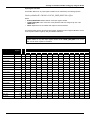
Input Register Variables
The Modbus address for any input register variable can be calculated by the following equation.
EndereçoModbusIR = 300.001 + LOCAL_MOD_MAP * 80 + Offset
Where:
• EndereçoModbusIR: Modbus address of the input register variable.
• LOCAL_MOD_MAP: value of the same name parameter that was configured by user in the
TBWH block.
• Offset: displacement of the variable with respect to the base address
The following table presents the DF100 input register variables that are mapped to Modbus, as well
as its respective offsets, lengths (in bits), and Modbus addresses.
NOTE
The Modbus addresses were calculated for few LOCAL_MOD_MAP values. If you need the
Modbus address of any other input register variable whose LOCAL_MOD_MAP is not on the
table, use the above equation to calculate it.
Input Register Variable Number of Offset
Registers
LOCAL_MOD_MAP
0
1
2
3
4
5
10
20
30
40
50
99
HART_PV.Status
1
0
300001
300081
300161
300241
300321
300401
300801
301601
302401 303201
304001
307921
HART_PV.Value
2
1
300002
300082
300162
300242
300322
300402
300802
301602
302402 303202
304002
307922
HART_SV.Status
1
3
300004
300084
300164
300244
300324
300404
300804
301604
302404 303204
304004
307924
HART_SV.Value
2
4
300005
300085
300165
300245
300325
300405
300805
301605
302405 303205
304005
307925
HART_TV.Status
1
6
300007
300087
300167
300247
300327
300407
300807
301607
302407 303207
304007
307927
HART_TV.Value
2
7
300008
300088
300168
300248
300328
300408
300808
301608
302408 303208
304008
307928
HART_QV.Status
1
9
300010
300090
300170
300250
300330
300410
300810
301610
302410 303210
304010
307930
HART_QV.Value
2
10
300011
300091
300171
300251
300331
300411
300811
301611
302411 303211
304011
307931
HART_5V.Status
1
12
300013
300093
300173
300253
300333
300413
300813
301613
302413 303213
304013
307933
HART_5V.Value
2
13
300014
300094
300174
300254
300334
300414
300814
301614
302414 303214
304014
307934
HART_6V.Status
1
15
300016
300096
300176
300256
300336
300416
300816
301616
302416 303216
304016
307936
HART_6V.Value
2
16
300017
300097
300177
300257
300337
300417
300817
301617
302417 303217
304017
307937
HART_7V.Status
1
18
300019
300099
300179
300259
300339
300419
300819
301619
302419 303219
304019
307939
HART_7V.Value
2
19
300020
300100
300180
300260
300340
300420
300820
301620
302420 303220
304020
307940
HART_8V.Status
1
21
300022
300102
300182
300262
300342
300422
300822
301622
302422 303222
304022
307942
HART_8V.Value
2
22
300023
300103
300183
300263
300343
300423
300823
301623
302423 303223
304023
307943
PRIMARY_VALUE.Status
1
24
300025
300105
300185
300265
300345
300425
300825
301625
302425 303225
304025
307945
PRIMARY_VALUE.Value
2
25
300026
300106
300186
300266
300346
300426
300826
301626
302426 303226
304026
307946
BLOCK_TAG
16
27
300028
300108
300188
300268
300348
300428
300828
301628
302428 303228
304028
307948
VAR_UNITS9
9
43
300044
300124
300204
300284
300364
300444
300844
301644
302444 303244
304044
307964
24.26
Creating a Foundation Fieldbus Strategy by using the DF100
Holding Register Variables
The Modbus address for any holding register variable can be calculated by the following equation.
EndereçoModbusHR = 404.001 + LOCAL_MOD_MAP * 20 + Offset
Where:
• EndereçoModbusHR: Modbus address of the holding register variable.
• LOCAL_MOD_MAP: value of the same name parameter that was configured by user in the
TBWH block.
• Offset: displacement of the variable with respect to the TBWH base address
The following table presents the DF100 holding register variables that are mapped to Modbus, as
well as its respective offsets, lengths (in bits) and Modbus addresses.
NOTE
The Modbus addresses were calculated for few LOCAL_MOD_MAP values. If you need the
Modbus address of any other holding register variable whose LOCAL_MOD_MAP is not on the
table, use the above equation to calculate it.
Holding Register
Variable
Number of
Registers
Offset
LOCAL_MOD_MAP
0
HART_VAR_CODE
S8
8
50
99
0 404001 404021 404041 404061 404081 404101 404201 404401 404601 404801 405001
1
2
3
4
5
10
20
30
40
405981
General notes about Native Addressing
• If the requested register in Modbus commands involves (exclusively or not) reserve address, the
DF100 will respond with a zero value for such register.
• The Modbus of DF100 is based on version known as Combined Scenario. Thus, the DF100
allows enabling / disabling the swap of variable registers of float type through the RTS_CTS
parameter of Modbus MBCF block.
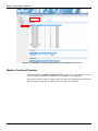
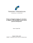
• The Modbus addresses, of any available Modbus point at DF100, may also be consulted
through the information page of the DF100 Web Server - see next figure. After launching it, if
necessary, use the arrows of decreasing or increasing advancement to determine the desired
value for the LOCAL_MOD_MAP. Once you determine the value of LOCAL_MOD_MAP,
Modbus addresses will be automatically updated.
24.27
DFI302 – User’s Manual – DEC/13 - K
Figure 24. 41 –Web page with Modbus addresses for LOCAL_MOD_MAP equals to zero
Modbus Combined Scenario
The DF100 supports the Modbus Combined Scenario, in which it is able to perform the role as
master and slave simultaneously via Modbus TCP / IP regardless of any configuration.
The selection between master and slave would only apply to the RS-485 port, which could be
communicating simultaneously to the Modbus TCP / IP on ETH1 and ETH2 ports.
24.28