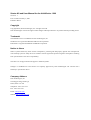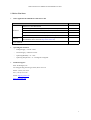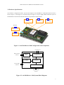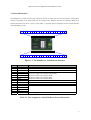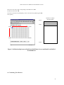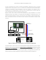
1
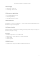
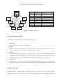
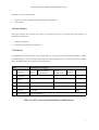
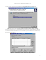
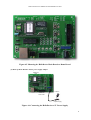
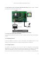
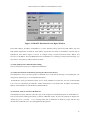
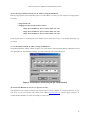
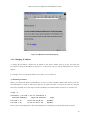
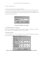
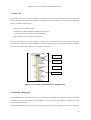
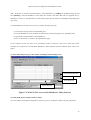
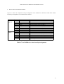
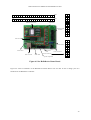
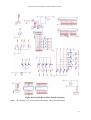
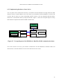
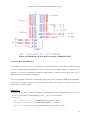
Starter Kit and User Manual for the
HelloDevice 1200
Version 1.2
Starter Kit and User Manual for the HelloDevice 1200
Version 1.1
Last revised on January 3, 2001
Printed in Korea
Copyright
Copyright 2000, Sena Technologies, Inc. All rights reserved.
Sena Technologies reserves the right to make changes and improvements to its product without providing notice.
Trademark
The HelloDevice™ is a trademark of Sena Technologies, Inc.
Windows® is a registered trademark of Microsoft Corporation.
Ethernet® is a registered trademark of XEROX Corporation.
Notice to Users
When a system failure may cause serious consequences, protecting life and property against such consequences
with a backup system or safety device is essential. The user agrees that protection against consequences resulting
from system failure is the user's responsibility.
This device is not approved for life-support or medical systems.
Changes or modifications to this device not explicitly approved by Sena Technologies will void the user's
authority to operate this device.
Company Address
Sena Technologies, Inc.
210 Yangjae-dong, Seocho-gu
Seoul, Korea 137-130
Telephone: +82-2-573-7772
Fax: +82-2-573-7710
Email: [email protected]
Website: http://www.sena.com
Table of Contents
1. Before You Start
2. Overview
3. Main Board Specifications
3.1. External Interface
3.2. Power Supply
3.3. Microprocessor
3.4. Ethernet Interface
3.5. Dual-Port RAM
3.6. Flash Memory
3.7. Firmware
4. Setting Up the Hardware
4.1. Installing Utility Software
4.2. Connecting Hardware
4.3. Setting Up Network
5. Quick Tour
5.1. Building a Homepage
5.2. Dual-Port Communication Demo Using Demo Board
6. Connecting User devices
6.1. Dual-Port RAM Communication
6.2. Communication Protocol
6.3. Setting Up Hardware
6.4. Sample Programs
Appendix A. Dual-port RAM Data Sheet
Appendix B. A/D Converter Data Sheet
Appendix C. IP address configuration by using crossover Ethernet cable
Starter Kit and User Manual for the HelloDevice 1200
1. Before You Start.
!" Items supplied in the HelloDevice 1200 Starter Kit
Items
Piece(s)
Hardware
Software
HelloDevice 1200 Main Board
1
5V Switching Mode Power Supply (SMPS) or Power Adaptor
1
HelloDevice 1200 Demo Board
1
Dual-port RAM Interface Cable (26 pins, 2.5mm pitch)
1
A/D Converter & I/O Interface Cable (20 pins, 2.5mm pitch)
1
HelloDevice Utility Software and Sample Demo Program
(Download the latest version at http://www.sena.com)
User’s Manual
1
1
!" Operating Environment
−
Voltage Supply = 5V DC ±10%
−
Current Supply = 200mA or lower
−
Operating Humidity = 0 ~ 95%
−
Operating Temperature = 0 ~ 50 Degrees Centigrade
!" Technical Support
Sena Technologies, Inc.
210 Yangjae-dong, Seocho-gu, Seoul, Korea 137-130
Phone: (+82-2) 573-7772
Fax: (+82-2) 573-7710
Email: [email protected]
http://www.sena.com
1
Starter Kit and User Manual for the HelloDevice 1200
2. Overview
The HelloDevice is a connectivity solution that allows any device in any industry to communicate over any
network, using any interface. The HelloDevice 1x00 product family is a board-level Ethernet controller that lets
manufacturers and system integrators connect devices such as home appliances and industrial control systems
directly to the Internet via Ethernet, and remotely communicate with and control them with standard web
browsers such as Microsoft Explore and Netscape Navigator. The HelloDevice 1x00 product family is
categorized into three types depending on how the HelloDevice connects to a user device:
!" Digital I/O communication module (HelloDevice 1100)
!" Dual-port RAM communication module (HelloDevice 1200)
!" Serial communication module (HelloDevice 1300)
Table 2.1 shows the basic specifications of the HelloDevice 1x00 Series.
Model
Basic Spec.
HelloDevice 1100
HelloDevice 1300
Scenix Sx52BD
(8 bits microprocessor, 50 MIPS)
512 Kb flash memory
(Saves user Web files)
CPU
Memory
Network
Connection
10 Base-T Ethernet Interface (IEEE802.3)
Connection to the
User device
Internet Protocol
Support
Utility Software
HelloDevice 1200
16 contact points digital
1 channel
input
2 KB dual port RAM
RS-232/485
16 contact points digital
Max. 38,400 bps
output
HTTP1 / SMTP / BOOTP
TCP / UDP
IP / ICMP / ARP
Ethernet (IEEE802.3)
HelloDevice utility software (for Windows 95/98/NT/2000 platform)
: IP addressing and Web page uploading
Table 2.1 Basic specifications of the HelloDevice 1x00
1
Currently, HTTP 1.1 specifications are supported.
2
Starter Kit and User Manual for the HelloDevice 1200
3. Hardware Specifications
The hardware configuration and the system block diagram of the HelloDevice 1200 Main Board are shown
below in Figure 3.1 and Figure 3.2. (The board layout in Figure 3.1 may be slightly different from the layout of
the HelloDevice main board in the Starter Kit for the performance improvement.)
1
External Interface
connector
2
Microprocessor
3
10Base T
Ethernet controller
Rear side
4
2KB Dual-port RAM
5
512 KB
Flash memory
Figure 3.1. the HelloDevice 1200 Configuration and Components
LED Interface
RJ45 connector
interface
10 Base-T
filter
512 KB
Flash Memory
Power supply
interface
Ethernet controller
(10 Base-T)
Sx52BD
microprocessor
2 KB Dual-Port RAM
Dual-Port RAM
interface
Figure 3.2. the HelloDevice 1200 System Block Diagram
3
Starter Kit and User Manual for the HelloDevice 1200
3.1 External Interface
The HelloDevice provides JP1 and JP2 connectors that has 38 signal pins for external interface, which allows
internal components of the main board such as microprocessor, Ethernet controller and dual-port RAM to be
interfaced with the user device. Figure 3.3 and Table 3.1 represent the pin assignment for the external interface
of the HelloDevice 1200.
BA0
BA1
BA2
BA3
BA4
1
BA5
2
3
BA6
4
5
BA7
6
7
BA8
8
BA9
BA10
BD0
BD1
BD2
BD3
BD4
BD5
BD6
BD7
GND
busy
IRQ
Read
CE
Write
9 10 11 12 13 14 15 16 17 18 19 20 JP1
40 39 38 37 36 35 34 33 32 31 30 29 28 27 26 25 24 23 22 21 JP2
Vcc
Rx-
Rx+
Tx-
Tx+
Led0
Led1
Led2
Reset
Figure 3.3. The HelloDevice 1200 External Interface
Pin
1~ 11
12 ~ 19
20
21
22
23
24
25
26
27 ~ 32
33 ~ 35
36
37
38
39
40
Symbol
BA0 ~ BA10
BD0 ~ BD7
GND
Write
CE
Read
IRQ
Busy
Reset
Not Used
LED0 ~ LED2
Tx+
TxRx+
RxVcc
Description
Dual-Port RAM Address
Dual-Port RAM Data
Ground
Dual-Port RAM Control Signal (Write)
Dual-Port RAM Control Signal (Chip Enable)
Dual-Port RAM Control Signal (Read)
Dual-Port RAM Control Signal (IRQ)
Dual-Port RAM Control Signal (Busy)
Microprocessor Reset
Ethernet Status Indicator LED (Tx, Rx, Collision)
RJ45 Connector Ethernet Data
Power Supply Vcc
Table 3.1. Pin Assignment of the HelloDevice External Interface
4
Starter Kit and User Manual for the HelloDevice 1200
3.2 Power Supply
!" Voltage Supply = 5V DC ±10%
!" Current Supply = 200mA or lower
3.3 Microprocessor Specifications
!" Scenix SX52BD 8 Bit Microprocessor
!" 4 Kbytes Program Memory
!" 52-pin PQFP (See Figure 3.1, part [2])
3.4 Ethernet Interface
The HelloDevice is connected to an Ethernet hub or switch by the RJ45 connector on the HelloDevice Demo
Board. Distances of up to 100m are supported.
3.4.1 Ethernet Controller
The Ethernet Controller provides the functions of framing and addressing data, and detecting and avoiding errors
and collisions (See Figure 3.1, Part [3]).
Specifications:
!" RealTek Full-duplex Ethernet Controller: RTL8019AS
!" Supports 10 base-5, 10 base-2 and 10 base-T compliant with IEEE802.3
!" 16 Kbytes SRAM
!" NE2000 Compatible
3.4.2 RJ45 Connector
!" Shielded Connector compliant with AT&T258 specifications (In Demo board)
5
Starter Kit and User Manual for the HelloDevice 1200
1=Tx+
8=NC
2=Tx-
7=NC
3=Rx+
4=NC
6=Rx-
Pin No.
Description
Red Line
1
Tx+
White with orange
2
Tx-
Orange
3
Rx+
White with green
4
Not used
Blue
5
Not used
White with blue
6
Rx-
Green
7
Not used
White with brown
8
Not used
Brown
5=NC
Figure 3.4. RJ45 connector
3.4.3 Status Indicator LED's
There are four status indicator LED’s which indicate the following.
!" Power LED
Indicates the Power-On status of the HelloDevice.
!" Rx LED
Indicates that the Ethernet controller is receiving Ethernet packets from the network. If it is correctly
connected to the network, this LED will blink when packets are received
!" Tx LED
Indicates that the Ethernet controller is sending packets.
Before setting the HelloDevice network
configuration, this LED will blink every second. After network configuration, if connected correctly, this
LED blinks only in response to requests from the user's PC, for example ping or server activity.
!" Collision LED
Indicates that one or more Ethernet packets transmitted from the Ethernet controller to the network may
have collided with another packets. In this case, the Ethernet controller will automatically resend the packets.
3.5 Dual-Port RAM
Dual-Port RAM is a 2 Kbytes duplex communication memory chip which both a user device and the
HelloDevice can read/write. This memory can be accessed through 8 data lines (BD0 ~ BD7) and 11 address
6
Starter Kit and User Manual for the HelloDevice 1200
lines (BA0 ~ BA10) of JP1 and JP2.
!" Cypress CY7C136 2 Kbytes Dual-Port RAM (See Appendix A)
!" 52-pin PQFP
3.6 Flash Memory
Web page resources files that the user creates to control the user device are stored in the flash memory of
HelloDevice Main Board.
!" 4 MBits (512 Kbytes)
!" Composed of 2,048 sectors of 256 Bytes.
3.7 Firmware
The HelloDevice Firmware resides in the program memory of microprocessor. The firmware includes a TCP/IP
stack conforming to the Open System Interconnection (OSI) requirements for an Internet connection, and the
dual-port RAM interface for connection to the user devices.
Layer
The HelloDevice Supports:
HTTP
Dual-Port RAM
Communication
7
Application
6
Presentation
5
Session
4
Transport
3
Network
TCP
2
Data link
IP / ICMP
1
Physical layer
Ethernet (IEEE802.3)
System
Configuration
BOOTP
UDP
ARP
Table 3.2. OSI 7 Layers and the HelloDevice 1200 Firmware
7
Starter Kit and User Manual for the HelloDevice 1200
4. Setting Up the Hardware
The HelloDevice 1200 is as follows:
!" Install the HelloDevice Utility Software on user's PC
!" Connect the HelloDevice to the power supply and Ethernet
!" Set the IP address of HelloDevice
!" Check the HelloDevice network connection.
4.1 Installing Utility Software
Run setup1x00.exe in the HelloDevice CD-ROM from the PC that is connect to the network. Setup1x00.exe can
be run in Microsoft Windows 95/98, NT and 2000. Select [Complete] and press [Next] button in the setup type
display screen.
Figure 4.1. Initial screen of the HelloDevice utility software installation program
8
Starter Kit and User Manual for the HelloDevice 1200
The setup program will automatically be installed onto c:\Program Files\HelloDevice utility folder.
Figure 4.2. Screen that shows the HelloDevice utility software is being installed
Once setup is completed, a shortcut icon of the HelloDevice Utility Software is created on the desktop and on the
program menu. If the following HelloDevice utility main window appears when the shortcut is clicked, the setup
has been successfully completed.
Figure 4.3. Initial screen for the HelloDevice utility software
9
Starter Kit and User Manual for the HelloDevice 1200
4.2 Connecting Hardware
The HelloDevice 1200 interfaces with your device through external interface pins only. Therefore, RJ45
connector and LED along with microprocessor should be implemented on the your device side, and the
HelloDevice 1200 will be plugged into it. The demo board in Starter Kit can be a good reference for your device
design. Figure 4.4 shows the HelloDevice 1200 Main Board and Demo Board.
Figure 4.4. The HelloDevice 1200 Main Board and Demo Board
(1)Plug Main Board onto the Demo Board through JP1 and JP2 connectors of the Main Board.
At this point, make sure that the JP1/JP2 of Main Board are connected to the corresponding JP1/JP2 of the Demo
Board, and pin numbers of both Main Board and Demo Board from 1 to 40 are connected properly. Figure 4.5
shows a picture of the HelloDevice mounted on Demo Board correctly.
Note:
Be sure to check not to reverse connection. The reverse connection makes fatal problem.
Fig 4.5 shows that HelloDevice is mounted on the demo board correctly.
10
Starter Kit and User Manual for the HelloDevice 1200
Figure 4.5 Mounting the HelloDevice Main Board on Demo Board
(2) Hook up Demo Board to the 5V power supply adapter.
HelloDevice
1200
110/220 V
HelloDevice
Demo board
5Vpower supply
Figure 4.6. Connecting the HelloDevice to 5V Power Supply
11
Starter Kit and User Manual for the HelloDevice 1200
(3) Connect Ethernet cable between Ethernet Hub and RJ45 connector. (Refer to chapter 3, Hardware
Specifications for the specifications of RJ45 connector.)
HelloDevice
1200
Power Collision
Rx
Tx
110/220 V
HelloDevice
Demo Board
Ethernet Cable
Hub or Switch
5V Power Supply
Ethernet backbone
Figure 4.7 Connecting the HelloDevice to Ethernet
(4) Check the status of the Tx LED on Demo Board.
Tx LED should be blinking every second. If not, there is a problem in the initial setting of the HelloDevice
hardware.
4.3 Configuring Network
In order for a HelloDevice to function as a server on the network, a static IP address must be set for the
HelloDevice. This section describes how to configure and change IP address for a HelloDevice.
4.3.1 Setting IP Address
The HelloDevice Utility Software is used to set up an IP address for a HelloDevice by utilizing BOOTP
(BOOTstrap Protocol), which is defined in the Internet protocol standard, RFC-951 and RFC-1542. The Utility
Software provides BOOTP a server function, and will respond to the BOOTP request of the HelloDevice.
Since the factory default setting of the HelloDevice IP address is 0.0.0.0, the HelloDevice sends BOOTP request
12
Starter Kit and User Manual for the HelloDevice 1200
for IP assignment, when it is powered up for the first time. Thus, users can see Tx LED keeps blinking
periodically as a reminder.
Since IP address of the HelloDevice is managed by an IP address database, a properly allocated MAC2-IP
address record should be entered into the database (See Figure 4.8). For a valid IP address, users should ask their
network administrator.
BOOTP database record
management function
BOOTP database list
BOOTP server function
IP address tracing/modifying function
Figure 4.8 IP address setting screen of the HelloDevice utility software
Take the following steps to set up the IP address, using the HelloDevice Utility Software.
Setting an IP address with the HelloDevice Utility Software:
(1) Run the HelloDevice Utility shortcut icon on the desktop of your PC and select [IP Set-up] menu click
on the [IP Set-up] window. This window provides the BOOTP server function for IP address setup (([BootP
Start], [BootP Stop]), trace function ([IP Find]) and IP address initialize functions ([IP Clear]).
(2) Press the [Add] button and enter the BOOTP database record as shown below.
2
MAC(Media Access Control) address is total 6 bytes and it is composed of 3 bytes-organization code and 3
bytes-product code. MAC address of HelloDevice is composed of 00-01-95 which is a company code and xx-xxxx which is a product code. E.g. 00-01-95-01-aa-08
13
Starter Kit and User Manual for the HelloDevice 1200
Figure 4.9 BOOTP Database Record Input Window
Enter MAC address, IP address of HelloDevice. 1 and 6 should be always entered for H/W address type and
H/W address length items for Ethernet. MAC address is printed on the sticker on the Ethernet controller chip of
HelloDevice main board. Figure 4.9 shows an example setting of 00:01:95:04:02:03 MAC address and
192.168.1.15 IP address. Since the BOOTP function of HelloDevice is working by using broadcast message, you
don’t have to enter gateway address and sub net mask.
(3) Click [Add] button to finish database editing.
The records entered in step (2) are added to the IP database.
(4) Launch the functions of BOOTP by pressing the [BootP start] button.
The HelloDevice Utility will then operate as a BOOTP server. Note that the message on the [Status] bar will
change from “Monitoring” to “Listening BOOTP request”.
If HelloDevice Utility gets BOOTP request from a certain HelloDevice which does not exist in BOOTP DB
List, it will run "DB Setting for BOOTP" window automatically. User should enter IP address and Gateway
address of the HelloDevice, and add them to BOOTP DB list.
(5) Check the status of Tx LED on HelloDevice.
The HelloDevice Utility Software will send a reply for IP assignment to the BOOTP request of the HelloDevice.
The Tx LED will be blinking periodically to indicate a BOOTP request. At this point, [Status] bar displays the
“BootP reply sent... [ 192.168. 1. 15 ]” message. Wait until Tx LED does not blink any longer, and then stop
the functions of BOOTP server by clicking [BOOTP Stop] button.
14
Starter Kit and User Manual for the HelloDevice 1200
(6) Use the ping command to check your IP address setting of HelloDevice.
Run the ping program at the command prompt. If your IP address is correctly set, the response to the ping will be
as follows:
>> ping 192.168.1.15
>> Pinging 192.168.1.15 with 32 bytes of data:
Reply from 192.168.1.15: bytes=32 time=10ms TTL=251
Reply from 192.168.1.15: bytes=32 time<10ms TTL=251
Reply from 192.168.1.15: bytes=32 time=10ms TTL=251
If the response above is not displayed, the IP address was not entered correctly, so you should repeat steps (4),
(5) and (6).
(7) Use [IP Find] to identify IP address setting of HelloDevice.
Click [IP Find] button, and the window in figure 4.10 will be shown. Enter the MAC address of HelloDevice and
click [Find] button. The IP address currently set in the “Found IP” item will be displayed.
Figure 4.10 IP address check using the [IP Find] function
(8) Check if the HelloDevice web server operates correctly.
The HelloDevice has a built-in 404.html file in flash memory (factory default). To check the functions of your
web server, run any web browser and connect to the address http://192.168.1.15. The web page in Figure 4.11
verifies that the HelloDevice works successfully as a web server.
15
Starter Kit and User Manual for the HelloDevice 1200
Figure 4.11 HelloDevice default Web page
4.3.2 Changing IP address
To change the IP address, initialize the IP address to the factory default value of 0.0.0.0, and repeat the
procedures of setting an IP address in section 4.3.1. At this point, ask your network administrator for a new IP
address.
For example, let's try to change IP address of 192.168.1.15 to 192.168.1.18.
(1) Initializing IP address
Before you initialize IP address of HelloDevice, you have to remove IP/MAC address data stored in your PC.
This information is stored in ARP cache, and you can make sure what is stored in the cache by using the
following command. This is the response of the command in case that IP address of user PC is 192.168.1.100.
>>arp -a
Interface: 192.168.1.100 on Interface 2
Internet Address
Physical Address
Type
192.168.1.15
00-01-95-04-02-03
dynamic
192.168.1.23
01-a0-11-34-11-0d
dynamic
Remove the corresponding item to the current HelloDevice information by using the following command.
16
Starter Kit and User Manual for the HelloDevice 1200
>> arp –d 192.168.1.15
Now, you are ready to initialize current IP address of HelloDevice.
Go to [IP Setup] window and click [IP Clear] button to display a window where you can clear the IP address. If
you want to clear the current IP address of 192.168.1.15, just enter the current setting of the IP address as shown
below in figure 4.12 and click [OK] button. Then, the present IP address of 192.168.1.15 set on HelloDevice will
be changed to factory default of 0.0.0.0.
Figure 4.12 IP address Clear window
(2) Verifying the initialization of an IP address
Check if Tx LED of HelloDevice blinks. When an IP address is initialized, the HelloDevice will send the
BOOTP request message. The Tx LED of the HelloDevice will keep blinking.
(3) Resetting an IP address
To reset an IP address to 192.168.1.18, edit/modify the contents of the IP address database using the [Edit]
function and repeat the procedures of setting an IP address in section 4.3.1.
Figure 4.13 IP address change using the [Edit] function in the IP address database
17
Starter Kit and User Manual for the HelloDevice 1200
5. Quick Tour
This chapter shows how to build a homepage on the HelloDevice web server and demonstrates the Dual-Port
RAM communication between the HelloDevice Main Board and Demo Board. The following sample program
files are included in the Starter Kit.
(1) First web server demo sample
(2) Sample for web-based Dual-Port RAM communication
(3) Java applet source code for Dual-Port RAM demo
(4) C program source for Dual-Port RAM demo
Section 5.1 describes how to use the sample (1) to start a web server for the first time, while section 5.2 provides
an exercise to communicate with the HelloDevice Dual-Port RAM over the web using the sample (2). Samples
of (3) and (4) are described in chapter 6, Connecting User Devices.
Sample (1)
Sample (2)
Sample (4)
Sample (3)
Figure 5.1 Location of the HelloDevice Sample Files
5.1 Building a Homepage
For the HelloDevice to function as a web server, web resources like HTML files, image files, and Java class files
should be stored on the flash memory of the HelloDevice up to 256 files or a total data size of 500 Kbytes can be
stored on the flash memory.
Since the HelloDevice does not use a general operating ststems, web files are managed in the form of “file index
18
Starter Kit and User Manual for the HelloDevice 1200
table”. Web files are stored in the flash memory of the HelloDevice by building an integrated image file and
then uploading it onto the HelloDevice. This image file contains a file index table that is recognized only by
HelloDevice web server. The HelloDevice Utility Software provides the functions of building and uploading this
type of file.
To make HelloDevice function as a web server, perform the following steps:
(1) Create the web pages with a web-publishing tool.
(2) Use the HelloDevice Utility Software to transform the created web pages into an uploadable form.
(3) Upload the transformed files to the HelloDevice.
(4) Use a web browser to connect to the uploaded web page.
In this example, use the web files in the “FirstDemo” folder to construct a web server home page. These
examples are composed of: an index.html, HelloDevice block diagram and cube animation demo with a Java
applet.
(1) Select [Web files] tab to go to the window containing web file manager tools.
Find and Build Web File
List box clear
Select Build File
Upload Built File
Figure 5.2. Web File Tool screen of the HelloDevice Utility Software
(2) Click [Find] button to find web files to build.
Go to the folder containing the example files, select the top-level “FirstDemo” folder, and click [OK] button.
19
Starter Kit and User Manual for the HelloDevice 1200
Figure 5.3. Finding Web server demo files
(3) Select a file name to build.
Enter the file name of the built image and click [Save] button to save. By default the HelloDevice web files built,
will have the extension “hd”. The current window closes and “Build complete” dialog box appears.
Figure 5.4. Saving Web sample Build file
(4) Enter an IP address of the HelloDevice to upload the built files.
20
Starter Kit and User Manual for the HelloDevice 1200
It is assumed that the IP address of HelloDevice is 192.168.1.15, as is shown in chapter 4.
Figure 5.5. Entering the IP address to upload the built files
(5) Click the [Target file] button to select the built image files to upload.
Figure 5.6. Screen of selecting the Build files to upload
(6) Click [Upload] button to upload the built image files to HelloDevice.
21
Starter Kit and User Manual for the HelloDevice 1200
This procedure is displayed on the Progress bar, and when it has finished, a “Flash download completed!!”
dialog box will appear.
(7) Enter URL http://192.168.1.15/index.html in the web browser, and try connecting.
The web page in Figure 5.7 will appear. If not, you might not have entered the value of the IP address correctly
and as a result the web server will not operate successfully. If the web page fails to appear, check the IP
address setting of web server and reload the file.
Figure 5.7. HelloDevice, “FirstDemo” Web page screen
A user's homepage can be customized in the same way as described above.
22
Starter Kit and User Manual for the HelloDevice 1200
5.2 Dual-Port RAM Communication demo using Demo Board
The Starter Kit provides a Demo Board and sample programs for the demo of Dual-Port RAM communication.
This section describes how to run the demo.
Use sample web files of the HelloDevice Utility Software in “Demo\DPRDemo” folder to read and write the
contents of Dual-Port RAM of the HelloDevice (See Figure 5.1 for the location of the sample files). index.html,
dpram.jar and 404.html files in the folder are used.
(1) Modify index.html file in “DPRDemo” folder.
Enter IP address of the HelloDevice currently in the IP address parameter associated with Java applet within
index.html file. Save the file without modifying other parameters.
<HTML>
<HEAD>
<TITLE>Simulator</TITLE>
</HEAD>
<BODY>
<H1>DPRAM R/W demo</H1>
<APPLET CODE=Simulator.class ARCHIVE=dpram.jar WIDTH=520 HEIGHT=450>
<param name=host value="192.168.1.15">
<param name=port value=6001>
<param name=polling value=1>
</APPLET>
</BODY>
</HTML>
Figure 5.8. Modifying index.html for Dual-Port RAM Communication
Note:
Several parameters can be used for java applet of dual-port RAM communication.
IP address
: the HelloDevice IP address
TCP port
: Always set as 6001
Polling interval
: 10 ms resolution, Set proper value according to the application
e.g. “polling value =1” means that dual-port RAM will be polled at every 10 ms.
(2) Build and upload web files in “DPRDemo” folder.
Follow the procedure described in section 5.1 with web files in “DPRDemo” folder instead of “FirstDemo”
folder to upload these web pages to the HelloDevice.
23
Starter Kit and User Manual for the HelloDevice 1200
(3) When uploading has been completed, run the web browser to go to http://192.168.1.15/index.html page.
If the web page in figure 5.9 is not displayed, retry the procedure (2). If it continues to fail displaying the web
page, contact the Technical Support team at Sena Technologies.
Figure 5.9 Web Page for Dual-Port RAM Demonstration
This demo screen shows how to read and write the 255 bytes area of the HelloDevice Dual-Port RAM. The java
applet periodically reads and displays the Dual-Port RAM, the address of which is from 0x00 to 0xFE. You can
also change the 1-byte value of each address. Figure 5.10 shows the screen and the real mappings of Dual-Port
RAM. The value in the grids shown in Figure 5.9 will represent the current value of memory.
(4) Check if Dual-Port RAM has been written successfully.
Try changing the current value of Dual-Port RAM address 0x010 to 0xFF.
24
Starter Kit and User Manual for the HelloDevice 1200
Move the cursor to the grid corresponding to the address 0x10. #
Double-click the mouse. #
Enter FF in the edit box labeled [Hex:] which is located in the [Address] panel #
Press [Enter]
HelloDevice 2Kbyte
Dual-Port RAM
0x000
0x0FF
0x000
0x00F
0x0F0
0x0FF
0x800
Figure 5.10 Relationship between Dual-Port RAM Demo Screen and Dual-Port RAM of
the HelloDevice
6. Connecting User Devices
25
Starter Kit and User Manual for the HelloDevice 1200
In order to communicate with your device connected to the HelloDevice 1200 from the your PC, you should
implement Internet socket program of your PC. It should send a TCP/IP-based Dual-Port RAM Read/Write
command to the HelloDevice. When the HelloDevice receives this command, it will change the value of
specified location of its Dual-Port RAM, or sends current value of specified location to network. Finally, this
value is transmitted to the Internet socket interface program of you PC.
Figure 6.1 shows a basic concept of remote data communication by using the HelloDevice. You should
implement an Internet socket program or Java applet based on the HelloDevice communication protocol. You
should also implement hardware according to the specification of the HelloDevice Dual-Port RAM interface.
Refer to the Data Sheet attached to this manual for further information of the HelloDevice Dual-Port RAM,
CY7C136.
User's Device
192.168.1.15
: TCP
6001 Port
Interrupt
Data 0 ~ 7
HelloDevice
Communication
Protocol
Address 0 ~ 10
Microprocessor
Actuator
LCD
Sensor
Dual-Port RAM
Read Response
Dual-Port RAM
Read/Write Command
Ethernet
192.168.1.23
User PC
192.168.1.21
User PC
Figure 6.1 Remote data communication of the HelloDevice application
You should consider a couple of point of view in designing Dual-Port RAM communication system by using the
HelloDevice 1200. One is the communication from your device to the HelloDevice and the other is the one
from your PC to the HelloDevice. In your PC side, Dual-Port RAM Read/Write application should be
implemented based on TCP/IP protocol, either by using Java applet or socket application. In your device side,
hardware and firmware should be implemented to read and write Dual-Port RAM of the HelloDevice.
26
Starter Kit and User Manual for the HelloDevice 1200
6.1 Dual-Port RAM Communications
the HelloDevice has 2 Kbytes of Dual-Port RAM, the address of which is from 0x000 ~ 0x7FF. The first 2032bytes of the memory area is for user’s data, whereas the last 16-bytes is the registers for interrupt-based
communication. Your device may receive interrupt from the HelloDevice or can generate interrupt to the
HelloDevice, by using these registers. Figure 6.2 shows the HelloDevice memory map of Dual-Port RAM area.
0x000
DataArea
0x7EF
Reserved Reserved Reserved Reserved
IN
IN
IN
AddrMSB AddrLSB LenMSB
IN
OUT
OUT
OUT
LenLSB AddrMSB AddrLSB LenMSB
0x7F0
0x7F4
0x7F7
0x7F1
0x7F2
0x7F3
0x7F5
0x7F6
0x7F8
0x7F9
OUT Reserved Reserved INTR_R
LenLSB
INTR_L
0x7FA 0x7FB 0x7FC 0x7FD 0x7FE 0x7FF
Figure 6.2. the HelloDevice Dual-Port RAM memory map
As you can see 2032-bytes of user data area in the Figure 6.2, there’s no specified memory area mapping scheme
such as write area, read area, message box and so on. Various memory-map can be applied to this memory area,
based on your communication design scheme. Thus, you should be careful in implementation of communication
routines, since the memory mapping rule should be reflected in the memory-based communication routines.
For example, you may reserve the 1016-bytes of the memory area as InBox, from which the HelloDevice can
read data. The address of this area may be from 0x000 to 0x3F7. You may also reserve the rest of the data area
(0x3F8 ~ 0x7EF), as OutBox from which your device can read data.
In this case, you will have to implement the host-side application to read data from this InBox area. You can read
device information to make your device write device-specific data to this area. If interrupt-based communication
is required, interrupt control registers will be used in the communication.
Typically, there are two cases that users use interrupt-registers in the communication.
A. the HelloDevice requests your device to read data from its Dual-Port RAM area
This interrupt is used when the HelloDevice want to inform the your device of the fact that it has updated the
27
Starter Kit and User Manual for the HelloDevice 1200
certain area of Dual-Port RAM. Then, your device may perform certain device-specific tasks by using the data
read from the memory.
e.g. an interrupt service routine of your device may read specified memory area first and then it may display the
LCD screen from this data or may drive actuators from the data.
Note:
the HelloDevice does not have any interrupt reentrancy-protection mechanism. Thus, the processing time of the
interrupt service routine should be less than 5 ms, since the minimal time required to generate interrupt from the
HelloDevice is 5 ms. This is the case that next interrupt may be generated before the previous interrupt service
routine is finished. There will be no problem, if your device services interrupt from the HelloDevice in less than
5 ms. If a host application sends data at the interval larger than 5 ms, there may not be any problem.
B. Your device requests the HelloDevice to read data from Dual-Port RAM area
This interrupt is used when your device want to inform the HelloDevice of the fact that it has updated the certain
area of Dual-Port RAM. Then, the HelloDevice will read this data first and then it will send this data to the host
PC connected to the HelloDevice, by TCP/IP protocol.
e.g. your device may be composed of sensors for temperature, pressure or some other sensing units. Whenever
the sensor output is updated, your device may notify the fact to the HelloDevice. Eventually, the data will be sent
to application of host PC.
Note:
Interrupt generation interval of your device should be larger than 5 ms, since the minimal time required to
process interrupt from your device is 5 ms.
Fig 6.3 shows the flow chart that the user device generates interrupting into the HelloDevice for sending data to
PC. Fig 6.4 shows the flow chart that HelloDevice generates interrupting of dual port ram Read to the user
device so that user device can read data from the HelloDevice. The terminologies, IN/OUT used in the figure are
described in terms of interrupt direction. In the HelloDevice side, it will be In, if interrupt is generated into the
HelloDevice from your device or vice versa. The symbols of OUTAddr, OUTLen, INAddr, INLen is described in
Table 6.1, Interrupt control register.
28
Starter Kit and User Manual for the HelloDevice 1200
Write data
Update data in Dual-Port RAM
Write INAddr
Write the address of data written
Write INLen
Write the length of data written
Write 0xAA to INTR_L
Generate interrupt
Interrupt
Return
Figure 6.3. User device is generating interrupt into the HD1200
Interrupt
into user device
-
INTR_L register = 0xAA
nIRQ pin = LOW
Read OUTAddr
User device reads
specified address of Dual-Port RAM.
Read OUTLen
User device reads
specified length of the data.
Read data
Do something
User device reads data
From specified address By specified length
User device perform certain tasks
by using the data read
Return
Figure 6.4. User device data handling process after HD1200 generates interrupt into the user device
29
Starter Kit and User Manual for the HelloDevice 1200
Symbol
INAddrMSB
Address
0x7F4
INAddrLSB
0x7F5
INLenMSB
0x7F6
INLenLSB
0x7F7
OUTAddrMSB
0x7F8
OUTAddrLSB
0x7F9
OUTLenMSB
0x7FA
OUTLenLSB
0x7FB
INTR_R
0x7FE
INTR_L
0x7FF
Description
MSB Address of the data to be sent to host PC when interrupt is generated into
the HelloDevice from user device
LSB Address of the data to be sent to host PC when interrupt is generated into
the HelloDevice from user device
MSB length of the data to be sent to host PC when interrupt is generated into the
HelloDevice from user device
LSB length of the data to be sent to host PC when interrupt is generated into the
HelloDevice from user device
MSB Address of the data to be read by user device when interrupt is generated
into user device
LSB Address of the data to be read by user device when interrupt is generated
into user device
MSB length of the data to be read by user device when interrupt is generated
into user device
LSB length of the data to be read by user device when interrupt is generated into
user device
Used that HelloDevice generates interrupt into user device.
If the HelloDevice sets this register value as 0xAA, interrupt will be generated
into user device.
Used that user device generates interrupt into the HelloDevice.
If user device sets this register value as 0xAA, interrupt will be generated into
the HelloDevice.
Table 6.1. the HelloDevice Dual-Port RAM interrupt control register
6.2 Communication Protocol
To read and write the HelloDevice Dual-Port RAM remotely on the Internet, the Internet socket interface
program should be implemented on the your PC to communicate with the HelloDevice. This socket interface is
usually implemented in the form of a socket program written in C or Java applet working on the web.
The Internet socket interface should be implemented to allow the TCP/IP protocol to communicate with the
HelloDevice, and it should send Read/Write command to the TCP port 6001 and current IP address of the
HelloDevice. The HelloDevice will interpret this command to read and write Dual-Port RAM of the HelloDevice.
The communication command and corresponding response between socket interface and the HelloDevice are
summarized in Table 6.2.
Command
Packets
Dual-Port RAM Read
Get command
Get response
Set command
Dual-Port RAM Write
Direction
User PC
the HelloDevice
#
$
#
Table 6.2 the HelloDevice Dual-Port RAM Read/Write Command and Response
30
Starter Kit and User Manual for the HelloDevice 1200
The address of 2 Kbytes of Dual-Port RAM is from 0x000 to 0x7EF. So you should consider this scope in
designing communication interface between your system and the HelloDevice.
6.2.1 Reading a Dual-Port RAM
To read specified area of the HelloDevice Dual-Port RAM from your PC, you should send corresponding
commands into the HelloDevice from socket interface program of PC. the HelloDevice will reply to this
command and returns corresponding response. The Read command and corresponding response are summarized
in table 6.3. As it is shown as the table 6.3, the maximum readable data length is limited to 1450(=0x5AA) byte.
This limitation is from the fact that maximum number of bytes that can be sent in Ethernet frame is 1500 bytes
including header lengths of TCP/IP.
Command
Number of Byte
1
2
3
4
5
…
0x77
Dual-Port RAM
Data length
Address
(0x000 ~ 0x05AA)
(0x0000 ~ 0x07EF)
Address of
Length of
Data value of the
Response data
Response data
specified size
Read command
Read response
Table 6.3. the HelloDevice Dual-Port RAM Read protocol
This is the command that will read specified address of HelloDevice Dual-Port RAM and will be followed by the
corresponding response.
Let’s say that you want to read 4 bytes of data, the address of which starts from 0x10. If the current data of that
address is 0x12345678, it will be displayed like table 6.4.
0x00
Address
0x77
0x00
Command
Address
0x10
0x10
0x00
Length
0x00
0x04
Length
0x04
0x12
Data
0x34
0x56
0x78
Table 6.4. Example of Dual-Port RAM Read command/response
6.2.2 Writing a Dual-Port RAM
This command is used to change specified length of data in a specified location of Dual-Port RAM. It does not
require any response from the HelloDevice. The maximum writing data length is also limited to 249(=0x0F9)
31
Starter Kit and User Manual for the HelloDevice 1200
byte.
Type
Number of Bytes
1
2
3
0x78
Dual-Port RAM
Address
(0x000 ~ 0x7EF)
Write
command
4
5
Data length
(0x001 ~ 0x5AA)
6
7~
Interrupt Data
Flag
(Max. 1450 bytes)
Table 6.5. the HelloDevice Dual-Port RAM Write protocol
If you want to generate interrupt into user device after writing data to Dual-Port RAM, you have to set interrupt
flag as 0xAA when you transmit TCP packet.
Let’s say that you want to write a 4-byte data of 0x12345678 to the Dual-Port RAM address 0x0FF of the
HelloDevice, you should send the command as listed in table 6.6.
0x78
0x00
Command
Address
0xFF
0x00
0x04
Length
0xAA
0x12
Interrupt
Data
0x34
0x56
0x78
Table 6.6. Example of Dual-Port RAM Write command
6.3 Setting Up Hardware
6.3.1 the HelloDevice Dual-Port RAM Demo Board
A Demo Board is designed to supply power to the HelloDevice, to provide interface with Ethernet by RJ45
connector, and to communicate with your board through Dual-Port RAM using Dual-Port RAM interface
connector. Depending on the your board implementation, he can run simple I/O control demo and A/D converter
demo by using built-in components of the Demo Board. Demo Board is composed of the following modules.
!" The HelloDevice interface
−
40 pin connector for the HelloDevice interface
!" User board interface
−
1 channel A/D converter
−
4 point Input switch / 4 point output LED
−
26 pin Dual-Port RAM interface connector
−
20 pin I/O, A/D converter interface connector
!" Power adapter jack
32
Starter Kit and User Manual for the HelloDevice 1200
!" RJ45 connector for Ethernet interface
Figure 6.5 shows the components and pin assignment of the HelloDevice Dual-Port RAM Demo Board.
Interface pin assignment is also summarized in Table 6.7.
Connector
DPRAM
ADC &
IO
Pin
1
2 ~ 12
13 ~ 20
21
22
23
24
25
26
1~8
9
10
11
12
13 ~ 16
17 ~ 20
Symbol
Vcc
BA0 ~ BA10
BD0 ~ BD7
nBusy
NIRQ
nRead
NCE
nWrite
NGND
DB0 ~ DB7
ADRD
ADCS
ADINTR
ADWR
IN0 ~ IN3
OUT0 ~ OUT3
Description
Vcc
Dual-Port RAM address line
Dual-Port RAM data line
Dual-Port RAM control line (Busy)
Dual-Port RAM control line (IRQ)
Dual-Port RAM control line (Read)
Dual-Port RAM control line (Chip Enable)
Dual-Port RAM control line (Write)
GND
AD converter 8 bit data line
AD converter control line (Read)
AD converter control line (Chip Select)
AD converter control line (Interrupt)
AD converter control line (Write)
4 point input line
4 point output line
Table 6.7. the HelloDevice demo board pin assignment
33
Starter Kit and User Manual for the HelloDevice 1200
21 22 23 24 25 26 27 28 29 30 31 32 33 34 35 36 37 38 39 40
JP2
20 19 18 17 16 15 14 13 12 11 10
JP1
26 25
24 23
22 21
9
8
7
HelloDevice interface
6
5
4
3
2
1
20 19
18 17
4 point Input
switch/LED
16 15
14 13
12 11
Dual-Port RAM
connector
10
9
8
7
6
5
4
3
2
1
A/D converter
20 19
18 17
Variable resistor
16 15
14 13
12 11
Reset switch
RJ45 connector
A/D converter
I/O
Control connector
Power connector
Status LED
10
9
8
7
6
5
4
3
2
1
4 point output LED
Figure 6.5 the HelloDevice Demo Board
Figure 6.6 shows a Schematic of the HelloDevice Demo Board. You can refer to this to design your own
hardware for the HelloDevice interface.
34
Starter Kit and User Manual for the HelloDevice 1200
Figure 6.6 the HelloDevice Demo Board Schematic
Note:
JP3(Debug J1,J2) is connected with jumper when you make board
35
Starter Kit and User Manual for the HelloDevice 1200
6.3.2 Implementing hardware of user device
You can perform data communication between your hardware and the HelloDevice through Dual-Port RAM
interface connector of Demo Board. You can also hook up your hardware with the HelloDevice, and test A/D
converter and I/O control, by using corresponding interface connector. You may implement Dual-Port RAMbased device control/monitor demo by using both interface. Figure 6.7 shows the conceptual diagram of using
Demo Board to implement the Dual-Port RAM communication.
HelloDevice
Dual-Port RAM
HelloDevice
Dual-Port RAM
Interface
Dual-Port RAM
Interface
Microprocessor
Dual-Port RAM
HelloDevice demo board
I/O, ADC
Interface
I/O, ADC
Interface
User board
Figure 6.7. Concept diagram of the HelloDevice Dual-Port RAM communication demo
This section focuses on the way your hardware communicates with the HelloDevice Dual-Port RAM, and
describes how to use Demo Board to test I/O control and A/D converter control.
36
Starter Kit and User Manual for the HelloDevice 1200
Figure 6.8. HelloDevice & User Device use ports of Dualport RAM
1) Dual-Port RAM Communication
To implement the hardware, refer to the specifications of the HelloDevice external interface, Dual-Port RAM
connector of Demo Board and attached data sheet of CY7C136 Dual-Port RAM. When you implement your
hardware, you can use Vcc/GND lines of Dual-Port RAM interface connector of Demo Board. This way an
additional 5V DC power supply is not required.
This section illustrates a subroutine of reading and writing each one byte in Dual-Port RAM of the HelloDevice
to help you to implement firmware of your user-defined device. This example is written in Scenix Sx
microprocessor assembly language.
Read memory
To read Dual-Port RAM, specify the address for DPROffsetLSB and DPROffsetLSB and then call
_dpramread subroutine. To read multiple bytes, call _dpramread several times.
_dpramread
mov
!datalo,#$FF
; Set Data Read line as input (refer to pin 19 ~ 26)
mov addlo, DPROffsetLSB ; Set memory address (Address 0 ~ 7) : refer to 9 ~ 16
mov addhi, DPROffsetMSB ; Set memory address (Address 8 ~ 10): refer to 17 ~ 18, 33
37
Starter Kit and User Manual for the HelloDevice 1200
; Ser as Read Active (pin 30, nWR=HIGH)
setb
rw
clrb
dpramcs
; Chip Enable (pin 31, nCE=LOW)
mov Scratch0, datalo ; Read data from Data line and save it to Scratch0 variable (refer to pin 19~26)
setb
; Chip Disable (pin 31, nCE=HIGH)
dpramcs
; Save the value of Scratch0 into w register
mov w, Scratch0
retp
Write memory
To write Dual-Port RAM, specify address for DPROffsetLSB and DPROffsetLSB, save appropriate 1 byte
value to w-register, and call _dpramwrite subroutine. To save multiple byte values, call _dpramwrite
several times.
_dpramwrite
; Save the data to be written to Scratch0 variable
mov Scratch0, w
mov
; Set Data Read line as output (refer to pin 19 ~ 26)
!datalo,#$00
mov addlo, DPROffsetLSB ; Set memory address (Address 0 ~ 7) : refer to pin 9 ~ 16
mov addhi, DPROffsetMSB ; Set memory address (Address 8 ~ 10): refer to 17 ~ 18, 33
mov datalo, Scratch0 ; Write the value of Scratch0 to Data line (refer to 19~26)
; Chip Enable (pin 31, nCE=LOW)
clrb
dpramcs
clrb
rw
; Set Write Active (pin 30, nWR=LOW)
setb
rw
; Clear Write Active (pin 30, nWR=HIGH)
setb
dpramcs
; Chip Disable (pin 31, nCE=HIGH)
retp
Generating interrupt into the HelloDevice
Before you generate an interrupt to the HelloDevice, you should specify the address and length of the data to be
read by the HelloDevice. In this sample, your device will specify the address value at InAddrMSB and
InAddrLSB of interrupt control register location, by writing as such. You will also specify the data length at
InLenMSB, InLenLSB, by writing such. And then, you will have to write data to the specified location. Next,
you will have to generate interrupt by writing 0xAA value to INTR_L register. Then, interrupt is generated into
the HelloDevice, and the HelloDevice will read the data written by user device. The following is a sample code.
InAddrMSB
equ
$7F4
InAddrLSB
equ
$7F5
InLenMSB
equ
$7F6
InLenLSB
equ
$7F7
OutAddrMSB
equ
$7F8
38
Starter Kit and User Manual for the HelloDevice 1200
OutAddrLSB
equ
$7F9
OutLenMSB
equ
$7FA
OutLenLSB
equ
$7FB
INTR_R
equ
$7FE
INTR_L
equ
$7FF
; Write specified address into InAddr.. registers
mov
DPROffsetMSB, #(InAddrMSB & $ff00)>>8
mov
DPROffsetLSB, #(InAddrMSB & $00ff)
mov
w, AddressMSB
call
@dpramwrite
mov
DPROffsetMSB, #(InAddrLSB & $ff00)>>8
mov
DPROffsetLSB, #(InAddrLSB & $00ff)
mov
w, AddressLSB
call
@dpramwrite
; Write specified length into InLen.. registers
mov
DPROffsetMSB, #(InLenMSB & $ff00)>>8
mov
DPROffsetLSB, #(InLenMSB & $00ff)
mov
w, LengthMSB
call
@dpramwrite
mov
DPROffsetMSB, #(InLenLSB & $ff00)>>8
mov
DPROffsetLSB, #(InLenLSB & $00ff)
mov
w, LengthLSB
call
@dpramwrite
; Write data for the loop count of specified length
mov
DPROffsetMSB, AddressMSB
mov
DPROffsetLSB, AddressLSB
……………
call
@dpramwrite
……………
; Generate interrupt by writing $AA into INTR_L register
mov
DPROffsetMSB, #(Intr_L&$ff00)>>8
39
Starter Kit and User Manual for the HelloDevice 1200
mov
DPROffsetLSB, #Intr_L&$00ff
mov
w, #$AA
call
@dpramwrite
Interrupt service routine of user device
If you receive interrupt from the HelloDevice, you should read data from the specified location. To read data at
the location, you should read address and length of data from OutBox register. And then, you will have to read
data from the address. After you finish reading the data, you will need to do something with this data.
; Read specified data address from OutAddr… registers
Mov
DPROffsetMSB, #(OutAddrMSB & $ff00)>>8
Mov
DPROffsetLSB, #(OutAddrMSB & $00ff)
call
@dpramread
mov
AddressMSB, w
Mov
DPROffsetMSB, #(OutAddrLSB & $ff00)>>8
Mov
DPROffsetLSB, #(OutAddrLSB & $00ff)
call
@dpramread
mov
AddressLSB, w
; Read specified data length from OutLen… registers
Mov
DPROffsetMSB, #(OutLenMSB & $ff00)>>8
Mov
DPROffsetLSB, #(OutLenMSB & $00ff)
call
@dpramread
mov
LengthMSB, w
Mov
DPROffsetMSB, #(OutLenLSB & $ff00)>>8
Mov
DPROffsetLSB, #(OutLenLSB & $00ff)
call
@dpramread
mov
LengthLSB, w
; Read data for the loop count of specified length
mov
DPROffsetMSB, AddressMSB
mov
DPROffsetLSB, AddressLSB
……………
call
@dpramread
……………
40
Starter Kit and User Manual for the HelloDevice 1200
; Do something required to control user device by using the data read
2) A/D Converter Test
Refer to the included specifications of both the HelloDevice external interface and Demo Board ADC connector
for hardware implementation. Next, refer to the A/D converter Data Sheet attached to this manual for National
Semiconductor’s ADC0804.. 8 data lines and 4 control lines are required for an A/D converter interface.
5V DC signal is connected to input line of A/D converter. By changing the value of 10K variable resistor on
Demo Board, the input value of A/D converter is changed. You can implement a simple program to read output
of A/D converter and to write this numeric to specified location of Dual-Port RAM. Eventually, you can test the
change of the A/D converter output, if you poll the HelloDevice Dual-Port RAM by using socket interface
program.
3) I/O Control Test
When you select the switch of Demo Board, a signal of 5V TTL level falls from high to low on the input line
(Low Active). Your device may read the status of input line and write the result to Dual-Port RAM. Also, your
device may read data from the specified location of Dual-Port RAM, and then turn on/off the LED of Demo
Board by setting output line as 5V HIGH level. If the output is High, LED turns on (High Active).
41
Starter Kit and User Manual for the HelloDevice 1200
6.4 Sample Programs
6.4.1 Using the Socket Program for Communication
The following C program source code shows how to implement Internet socket interface program for the
HelloDevice communication. This sample code is implemented to read and to write Dual-Port RAM data, by
using Berkeley socket C API functions. This source is a part of the entire source code “the HelloDevice
installation folder\Src\C\dprdemo.c”. TestThroughput() function is for testing the maximal speed of the
communication in your network environment.
//--------------------// Process Test Throughput
//--------------------void TestThroughput()
{
unsigned char
commandBuf[5], *ResponseBuf ;
int
commandLen, lenReceived ;
int
j, total_length=0 ;
int
offset, length, tmp ;
double bps=0 ;
int err, loop ;
int clientLen ;
clock_t start, finish;
double duration;
// Enter loop count for this test...
printf("\nEnter loop count of this demo....\n>>") ;
// Read loop count
scanf("%d", &loop) ;
// Fix the size as 1450, which is max. of Ethernet packet size
// This is max. size of the DPRAM data that can be transferred in the HelloDevice
offset = 0 ;
length = 1450 ;
// Initialize TCP socket
TCPSocketInit() ;
// Make TCP command : 6-byte coce
// 1) Command ID
commandBuf[0] = DPRGet ;
// 2) DPRAM address
tmp = offset >> 8 ;
commandBuf[1] = tmp ;
tmp = offset & 0x00FF ;
commandBuf[2] = tmp ;
// 3) DPRAM length
tmp = length >> 8 ;
commandBuf[3] = tmp ;
tmp = length & 0x00FF ;
commandBuf[4] = tmp ;
// 4) Interrupt flag
commandBuf[5] = 0 ; // 0: Do not generate Interrupt to device, AA: Generate interrupt
commandLen = 6 ;
42
Starter Kit and User Manual for the HelloDevice 1200
// Initialize length count
total_length=0;
// Start time measurement
start = clock();
// Loop of send/receive
for (j=0; j<loop; j++)
{
// Send command to the HelloDevice
err = sendto
(
sock,
&commandBuf,
commandLen,
0,
(struct sockaddr*)&clientAddr,
sizeof(clientAddr)
) ;
if (err == -1)
{
perror("\nsend error\n");
exit (1);
}
// Response data = 4-byte address/length + data
ResponseBuf = (unsigned char *) calloc(length+4, sizeof(char)) ;
// Receive incomming packet....
lenReceived = recvfrom
(
sock,
ResponseBuf,
length+4,
0,
(struct sockaddr*)&clientAddr,
&clientLen
);
if (lenReceived < 0)
{
perror("\nError receiving???\n") ;
exit(0) ;
}
// Accumulate Total data length received so far...
total_length += length + 4 ;
// Clear receive length
lenReceived = 0 ;
free(ResponseBuf) ;
// Print progress count
printf("%dth loop\r", j) ;
}
// Finish the time measurment
finish = clock();
// Measure elapsed time in second
duration = (double)(finish - start) / CLOCKS_PER_SEC;
// Print result
printf("\n\n\n%2.3f seconds elapsed for %d loops...\n", duration, loop);
bps = ((total_length*8.0)/duration)/1000.0 ; // total bytes * 8 bit/byte / duration sec /
1000 (Kbps)
printf("Total %.1f Kbytes transferred...\n", (double)total_length/1000.0) ;
printf("%.3f Kbps throughput measured...\n", bps) ;
// Close TCP socket
TCPSocketClose() ;
43
Starter Kit and User Manual for the HelloDevice 1200
}
//--------------------// Process DPR Read
//--------------------void DPR_Read()
{
unsigned char
commandBuf[5], *ResponseBuf ;
int
commandLen, lenReceived ;
int
i, count, err ;
int
clientLen ;
int
offset, length, tmp ;
printf("\n\nEnter offset in hex (MAX. 0x7FF):") ;
scanf("%x", &offset) ;
printf("\nEnter length in digit (MAX. 1450):") ;
scanf("%d", &length) ;
// Initialize TCP socket
TCPSocketInit() ;
// Make TCP command
// 1) Command ID
commandBuf[0] = DPRGet ;
// 2) DPRAM address
tmp = offset >> 8 ;
commandBuf[1] = tmp ;
tmp = offset & 0x00FF ;
commandBuf[2] = tmp ;
// 3) DPRAM length
tmp = length >> 8 ;
commandBuf[3] = tmp ;
tmp = length & 0x00FF ;
commandBuf[4] = tmp ;
// 4) Interrupt flag
commandBuf[5] = 0 ;
interrupt
//
0:
Do
not
generate
Interrupt
to
device,
AA:
Generate
commandLen = 6 ;
// Send command to the HelloDevice
err = sendto
(
sock,
&commandBuf,
commandLen,
0,
(struct sockaddr*)&clientAddr,
sizeof(clientAddr)
) ;
if (err == -1)
{
perror("\nsend error\n");
exit (1);
}
// Allocate buffer for incoming packet
ResponseBuf = calloc(length+4, sizeof(char)) ;
// Receive incomming packet....
lenReceived = recvfrom
(
sock,
ResponseBuf,
44
Starter Kit and User Manual for the HelloDevice 1200
length,
0,
(struct sockaddr*)&clientAddr,
&clientLen
);
if (lenReceived < 0)
{
perror("\nError receiving???\n") ;
exit(0) ;
}
// Store memory status for future use
for (i=0, count=0; i<length; i++)
{
printf("%2.2x:\t", ResponseBuf[i+4]) ;
if (count == 9)
{
count = 0 ;
printf("\n") ;
}
count++ ;
}
printf("\n\n") ;
// Display incoming packet size
printf("\n%d bytes received...\n\n", lenReceived) ;
// Free
free(ResponseBuf) ;
// Close TCP socket
TCPSocketClose() ;
}
//--------------------// Process DPRAM Write
//--------------------void DPR_Write()
{
char commandBuf[1450+6+1]="", data[1450+1] ;
int commandLen ;
int offset, length, tmp ;
int i, err ;
printf("\n\nEnter offset in hex (MAX. 0x7FF):") ;
scanf("%x", &offset) ;
printf("\nEnter length in digit (MAX. 1450):") ;
scanf("%d", &length) ;
printf("\nEnter value in hex:") ;
scanf("%s", data) ;
// Re-Initialize TCP socket
TCPSocketInit() ;
// Make TCP command
commandBuf[0] = DPRSet;
tmp =offset >> 8 ;
commandBuf[1] = tmp;
tmp = offset & 0x00FF ;
commandBuf[2] = tmp ;
tmp = length >> 8 ;
45
Starter Kit and User Manual for the HelloDevice 1200
commandBuf[3] = tmp ;
tmp = length & 0x00FF ;
commandBuf[4] = tmp ;
commandBuf[5] =0xAA;
interrupt
//
0:
Do
not
generate
Interrupt
to
device,
AA:
Generate
for (i=0; i<length; i++)
commandBuf[i+6] = data[i] ;
commandLen = 6 + strlen(data) ;
// Send command to the HelloDevice
err = sendto
(
sock,
&commandBuf,
commandLen,
0,
(struct sockaddr*)&clientAddr,
sizeof(clientAddr)
) ;
if (err == -1 )
{
perror("\nsend error\n");
exit (1);
}
}
6.4.2 Using Java applet for communication
The program source codes with Java applets, as demonstrated in section 5.2, are Simulator.java, RamPanel.java,
Util.java, ValueDisplayPanel.java and DPRComm.java located at “the HelloDevice installation folder\Src\java”
folder. You can access a web site and control the linked device remotely by creating web pages and inserting
applets written with these source codes into html files.
The following example shows how to implement Internet socket interface for sending and receiving signals
through TCP Port 6001 of the HelloDevice to control Dual-Port RAM with Java applets.
public synchronized byte[] readValue(int addr, int length) {
int inputData = 0;
int tmp = 0;
byte rxData[] = new byte[length+4];
byte retData[] = new byte[length];
byte[] data = new byte[5];
if (length > 0xff) length = 0xff;
data[0]
data[1]
data[2]
data[3]
data[4]
=
=
=
=
=
COMMAND_GET;
(byte) ((addr >> 8) & 0x000000ff);
(byte) (addr & 0x000000ff);
(byte) ((length >> 8) & 0x000000ff);
(byte) (length & 0x000000ff);
try {
socketTCP.getOutputStream().write(data, 0, data.length);
tmp = instream.read(rxData, 0, rxData.length);
if (tmp != -1)
{
46
Starter Kit and User Manual for the HelloDevice 1200
for (int i=0; i<256; i++)
retData[i] = rxData[i+4] ;
return retData;
}
} catch (Exception e) {
System.out.println("Err : " + e);
}
return data;
}
public synchronized void writeValue(int addr, int length, byte[] buffer) {
byte[] txData = new byte[ length + 6 ];
txData[0]
txData[1]
txData[2]
txData[3]
txData[4]
txData[5]
=
=
=
=
=
=
COMMAND_SET;
(byte) ((addr >> 8) & 0x000000ff);
(byte) (addr & 0x000000ff);
(byte) ((length >> 8) & 0x000000ff);
(byte) (length & 0x000000ff);
0 ; // Set interrupt flags as 0
System.arraycopy(buffer, addr, txData, 6, length);
// Initialize socket
try {
socketTCP.getOutputStream().write(txData, 0, txData.length);
} catch (Exception e) {
System.out.println("Err: " + e);
}
}
}
47
Starter Kit and User Manual for the HelloDevice 1200
Appendix A. Dual-port RAM Data Sheet
Provided in HelloDevice CD-ROM as PDF file format or
Can be downaloadable from Sena Technologies’ web site (http://www.sena.com)
Appendix B. A/D Converter Data Sheet
Provided in HelloDevice CD-ROM as PDF file format or
Can be downaloadable from Sena Technologies’ web site (http://www.sena.com)
48
Starter Kit and User Manual for the HelloDevice 1200
Appendix C. IP address configuration by using cross-over Ethernet cable
You may configure the wrong IP address for the HelloDevice that cannot be run in your current network
environment. You might not initialize the IP address of the HelloDevice before you install it to different network
environment. In these cases, you cannot access the HelloDevice via network, since only network-based IP
configuration function is provided in the HelloDevice.
In these cases, you will have to use cross-over Ethernet cable for communication with the HelloDevice. The
ordinary Ethernet cable is straight type, in which Rx line is connected into Rx line of other side and Tx line with
Tx line of other side. Meanwhile, crossover Ethernet cable is a cable with Rx connected to Tx of the other side,
and Tx to Rx of the other side.
Straight Ethernet cable
Cross-over Ethernet cable
Rx+
Rx+
Rx+
Tx-
Rx-
Rx-
Rx-
Tx+
Tx+
Tx+
Tx+
Rx-
Tx-
Tx-
Tx-
Rx+
You can emulate the 1:1 networking if you hook up cross-over cable between your PC and the HelloDevice,
without being affected by network routing. Take following steps for IP address reconfiguration.
1) Remove Ethernet cable from your PC
2) Directly hook up cross-over cable between your PC and the HelloDevice
HelloDevice
5Vpower suply
RJ45
User PC
Cross over
Ethernet
Cable
49
Starter Kit and User Manual for the HelloDevice 1200
3) Configure the network environment set-up of your PC so that it can communicate with the HelloDevice.
TCP/IP parameters of network configuration should be modified temporarily.
e.g. Let’s say that IP address of the HelloDevice is 192.168.1.23 and that of your PC is 172.168.1.22. Modify the
IP address of your PC and gateway as shown in the following picture.
You may modify the IP address to different IP address of 192.168.1.xx other than 192.168.1.23, since those
addresses can also be working in the subnet. Then, press [OK] button. You will have to keep in mind your
original network environment set-up parameters, since this is temporary set-up for IP address reconfiguration of
the HelloDevice.
4) Make sure if your PC can communicate with the HelloDevice by using ping utility
>> ping 192.168.1.23
>> Pinging 192.168.1.23 with 32 bytes of data:
Reply from 192.168.1.23: bytes=32 time=10ms TTL=251
Reply from 192.168.1.23: bytes=32 time<10ms TTL=251
Reply from 192.168.1.23: bytes=32 time=10ms TTL=251
5) Run the HelloDevice Utility program
6) Take steps described in chapter 4.3.2, “Changing IP address”
50