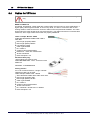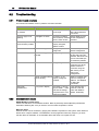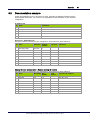
1
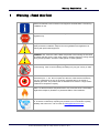
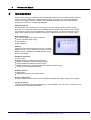
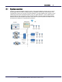
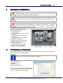
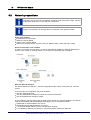
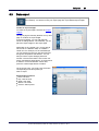
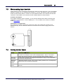
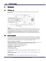
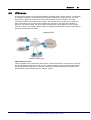
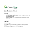
VPVision User
Manual
© 2014 VPInstruments
MAN-VP-V-UK
Revision:4
Date:2-1-2014
www.vpinstruments.com
VPVision User Manual
© 2014 VPInstruments
All rights reserved. No parts of this work may be reproduced in any form or by any means - graphic, electronic, or
mechanical, including photocopying, recording, taping, or information storage and retrieval systems - without the
written permission of the publisher.
Products that are referred to in this document may be either trademarks and/or registered trademarks of the
respective owners. The publisher and the author make no claim to these trademarks.
While every precaution has been taken in the preparation of this document, the publisher and the author
assume no responsibility for errors or omissions, or for damages resulting from the use of information
contained in this document or from the use of programs and source code that may accompany it. In no event
shall the publisher and the author be liable for any loss of profit or any other commercial damage caused or
alleged to have been caused directly or indirectly by this document.
Creation date: 2-1-2014 in (Delft)
Publisher
VPInstruments
Delft, The Netherlands
Contents
3
Table of Contents
1 Warning - Read this first
5
2 Introduction
6
1 System
...................................................................................................................................
overview
7
3 Quick start in 10 steps
8
4 Hardware installation
9
1 VPFlow
...................................................................................................................................
Scope configuration
9
2 Netw
...................................................................................................................................
ork preparations
10
3 PC
...................................................................................................................................
connection
11
5 Software installation
12
1 Configuration
...................................................................................................................................
backend
12
2 Settings
................................................................................................................................... 13
Us er s ettings
.......................................................................................................................................................... 13
Sys tem s ..........................................................................................................................................................
ettings
13
3 Inputs
................................................................................................................................... 14
4 Widgets
................................................................................................................................... 16
5 Pages
................................................................................................................................... 18
6 Reports
................................................................................................................................... 19
6 Daily use
22
1 Page
...................................................................................................................................
layout w ith w idgets
22
2 Real
...................................................................................................................................
time graphs
22
3 Data
...................................................................................................................................
ex port
23
7 Sensors and IO
24
1 VPFlow
...................................................................................................................................
Scope
24
2 RS485
...................................................................................................................................
Ethernet module
24
3 Mox
...................................................................................................................................
a analog input module
25
4 Analog
...................................................................................................................................
sensor types
25
8 Hardware
26
1 VPVision_M
................................................................................................................................... 26
2 Pow
...................................................................................................................................
er supplies
26
3 VPN
...................................................................................................................................
router
27
4 Cables
...................................................................................................................................
for VPVision
28
9 Apendix
29
1 Modbus
...................................................................................................................................
netw orks
29
3
4
VPVision User Manual
2 Troubleshooting
................................................................................................................................... 30
Pr oblem s..........................................................................................................................................................
and s olutions
30
Com m unication
..........................................................................................................................................................
is s ues
30
3 Documentation
...................................................................................................................................
ex ample
31
10 Terms and conditions of sale
© 2014 VPInstruments | MAN-VP-V-UK | Revision:4 | Date:2-1-2014
32
Warning - Read this first
1
5
Warning - Read this first
Read and understand user manuals of all equipment involved before commencing
installation or use.
All electrical installations to be carried out by authorized electrical installation
engineers only.
Compressed air can be dangerous! Please familiarize yourself with the forces
under pressurized conditions. Respect the local guidelines and regulations for
working with pressurized equipment.
WARNING: 100...250 VAC mains cables are present in the housing. Do not touch
the cables and thte power s upply when mains is applied. Keep the housing closed
during normal operation. Check the cable glands on water tightness.
Not intended for fiscal metering or billing. Our flow meters are not certified for
fiscal metering. Laws on fiscal metering and billing may vary per country or state.
Do not overestimate the results. The practical measurement uncertainty of
VPFlowScope is +/- 5%. Do not expect less than 5% measurement uncertainty
from any measurement as this is physically impossible due to the nature of
turbulent pipe flows. Our products are not intended to be used as a single means
to determine compressor capacity.
Make sure that the ambient temperature does not exceed the limits. Overheating
might cause temporary shutdown or permanent failure of the hardware.
Feedback leads to product improvement. Please share your experience with
us, as we are continuously improving our products in our commitment to quality,
reliability and ease of use. Let us know via [email protected]!
© 2014 VPInstruments | MAN-VP-V-UK | Revision:4 | Date:2-1-2014
6
2
VPVision User Manual
Introduction
Thank you for choosing VPVision! Let the savings begin! VPVision is a web based energy monitoring
system, primarily developed for compressed air systems. It monitors your entire compressed air
system from supply to demand. Thanks to the standardized hardware and the modular software
architecture, VPVision is scalable and adaptable.
About this manual
We have written this manual to help you to get the VPVision system up and running in no time.
There are some steps that require basic knowledge about IT systems and networks. This is where
you should get support of your IT department. In the entire manual, you will see small icons with a
page number. These refer to background information or additional information on a certain subject.
Basic components:
VPVision-M logger, with VPVision software
24 VDC 100 Watt power supply
Web interface
SQL database
Sensors:
VPVision support all VPInstruments sensors, and other
Modbus RTU or 4..20 mA based sensor types. For some
Modbus sensors, we offer pre installed drivers for quick
and easy installation.
Hardware extensions:
Touch screen
Modbus extension module with power supply
Modbus to Ethernet converter with power supply
Analog to Ethernet module with power supply
Modbus to Ethernet and analog to Ethernet module with power supply
Junction boxes for the RS485 network
Software options:
P&ID visuals
Additional inputs when exceeding 8 inputs
Service subscriptions
We offer a service contract, which covers all software upgrades and support. Contact us for details.
Language options:
VPVision is available in international English only. For translations you can access VPVision via real
time translation, using Google Translate.
© 2014 VPInstruments | MAN-VP-V-UK | Revision:4 | Date:2-1-2014
Introduction
2.1
7
System overview
VPVision is an Ethernet based monitoring system. The typical installation consists of the VPVisionM data logger with IO module for analog sensors and a Modbus network with VPFlowScopes. The
VPFlowScope sensors can be read out via direct RS485 or an indirect Modbus/TCP converter. The IO
modules are read out via an Ethernet interface. They can gather data from 4..20 mA based sensors,
and the default number of channels is 8 per analog IO module. VPVision is built around a powerful
database structure with integrated web server. This makes the system flexible and scalable to meet
the demands of virtually any compressed air installation.
© 2014 VPInstruments | MAN-VP-V-UK | Revision:4 | Date:2-1-2014
8
3
VPVision User Manual
Quick start in 10 steps
Step 1. Mount the VPVision cabinet
Unpack the box. Open the VPVision cabinet with the special key. Then remove all transport foam.
Check if all DIN Rail mounted equipment is still in place. If not, please fix the modules on the DIN
Rail. Installation by certified professionals only. Mount the VPVision-M on a wall and establish the
required Mains power connection. Read more about hardware installation here.
Step 2. Configure your VPFlowScope sensors
See VPFlowScope configuration. Assign the diameter and a Modbus address to each individual
sensor, so they can be found within the Modbus network.
Step 3. Assign IP addresses to all networking equipment
First, create a list of required IP addresses. See also Network Preparations. Document this list on
the configuration sheet. Get your laptop or PC, and connect it to the VPVision-M. Enter the
VPVision IP address to access the system. Now assign the IP addresses to the VPVision-M.
Depending on your system configuration, you also have to change the IP addresses of the Modbus
converters (see RS485- Ethernet module) and any remote IO modules (see Moxa analog input
module) you have. Save time! Ask us to pre-configure your IP addresses.
Step 4. Install the sensors
Ask your certified (electrical) installation subcontractor to install the VPFlowScope sensors in the
pipe, and connect it to the Modbus network. Install analog sensors and make a list of analog input
channels on your configuration sheet. See also the Documentation example.
Step 5. Configure inputs
Configure the input channels in VPVision. You can add the VPFlowScope and analog sensors via the
web interface. Use your configuration sheet as a reference for the channel names, sensor locations,
sensor ranges, diameter settings and so on.
Step 6. Configure widgets
Once the channels are in place, you can start to configure the widgets. Several types are available to
visualize all the data.
Step 7. Configure pages
Once the channels and widgets are in place, you can start to configure the pages. Assign the
widgets to the pages, make combinations of widgets and so on.
Step 8. Create your first report
Create your first reports using the reports module.
Step 9. Configure the optional touch screen
The touch screen PC is basically just a PC with a web browser. Startup the unit, run Firefox and type
in the VPVision-M IP address. That is all it takes.
Step 10. Use VPVision and save!
Now it is time to lean back, relax and monitor your entire system. See for example page layout with
widgets. Let us know how much you did save! We will reward every white paper or savings success
story with a nice gift. And if it's really good, we'll send in the press for an exclusive interview starring
you!
© 2014 VPInstruments | MAN-VP-V-UK | Revision:4 | Date:2-1-2014
Quick start in 10 steps
4
9
Hardware installation
Warning: Installation involves connection to mains. Installation of field cables requires
indepth knowledge and skills. Therefore all steps that involve electrical installation should
be carried out by certified installation professionals.
Make sure that the ambient temperature does not exceed the limits of the VPVision-M
cabinet (max 40 deg C | 104 F). Higher ambient temperature requires cabinet cooling.
Check if the earth wire (field ground) is free of interference and potential dangerous high
voltage. Make sure the circuit breaker is in off position. Then install the L, N and Earth
wire. The L, N and Earth may have a different color, depending on your local legislation
and directives for medium voltage systems.
Each VPVision-M consists of the
followingcomponents:
1. Circuit breaker
2. Main power supply, 24 VDC, 100 Watt.
3. VPVision-M
PostgreSQL database environment,
preinstalled
VPVision application, pre-installed
Webserver, pre-installed
4. RS485 connection terminal (fused
separately) with front cable entry.
5. Analog input module.
6. 24V connection terminal (fused
separately) with front cable entry.
7. Earth rail (for cable shielding)
4.1
VPFlowScope configuration
Set the Modbus addresses per VPFlowScope. Each VPFlowScope needs an individual address, in
order to be found in the Modbus network.
Always start with the V P FlowS c ope Modbus assignment before putting them into the
network. Label / Tag the V P FlowS c opes for convenience.
Use VPStudio to set:
Diameter
Modbus address
Other settings (Analog)
On the screen shot you can see the settings that
are key: diameter and Modbus address. Please
refer to the VPStudio manual for details.
© 2014 VPInstruments | MAN-VP-V-UK | Revision:4 | Date:2-1-2014
10
4.2
VPVision User Manual
Network preparations
You need to set your IP address to a STATIC IP address when connecting your
computer to the VPVision-M. The address should be within the same IP range. See the
configuration sheet which comes with your VPVision-M
Make sure that your IT department provides VPN access to the network for remote
support. If not possible, we strongly advice to install the 3/ 4G gateway module
Define your network
IP addresses must be unique
Gateway must be defined
Subnet mask must be defined
When using existing network structure: Get your address range: Check with client IT dept
General convention on IP numbers
To make it more easy to find a device, we will use the following guideline to assign IP addresses to
devices in the network. In existing networks, this might be not possible due to limitation.
Ethernet address example
The default address for LAN port 1: See the configuration leaflet, which comes with your VPVision
system.
As an example, the configuration may look as follows:
192.168.1.XXX VPVision-M
192.168.1.XXX RS485 to Ethernet converter for remote VPFlowScope
192.165.2.XXX Remote analog IO module
In most networks, the first three groups of digits will be 192.168.X. In specific situations, the network
might be AAA.BBB.C.XXX Where XXX (last three digits) may be assigned as follows:
0 Reserverd as network address, do not use
254 Reserverd as broadcast address, do not use
1 VPVision-M default address (can be changed when required)
2...20 Modbus to Ethernet converter (For VPFlowScope data transfer over Ethernet)
© 2014 VPInstruments | MAN-VP-V-UK | Revision:4 | Date:2-1-2014
Hardw are installation
11
21..40 Analog input modules(See also Moxa analog input module and Wago analog input module)
41...60 Other devices, for example Ethernet enabled kW meters
Example network configuration:
192.168.1.1 VPVision-M
192.168.1.2 VPFlowScope RS485 network, compressor house building 1
192.168.1.3 VPFlowScope RS485 network, compressor house building 2
192.168.1.21 Analog inputs, building 1
192.168.1.22 Analog inputs, building 2
192.168.1.41 Power meters, building 2
192.168.1.254 Gateway
4.3
PC connection
To connect your PC or Laptop, open the electrical
cabinet. You will see the VPVision-M unit. On the
VPVision-M you will find multiple Ethernet Ports.
By Default, LAN 1 is used for configuration.
Connect an Ethernet cable between Laptop (PC)
and the VPVision-M LAN 1. The Laptop should
have a static IP address within the same range as
the VPVision-M. Make sure the IP address is not
the same as the VPVision-M!
Open your webbrowser, type in the IP address of
the VPVision-M and you should see the startup
screen. Now you can configure the system (see
Configuration backend).
© 2014 VPInstruments | MAN-VP-V-UK | Revision:4 | Date:2-1-2014
12
VPVision User Manual
5
Software installation
5.1
Configuration backend
By clicking on the green puzzle icon, you enter the back-end of VPVision. In the
backend, the entire configuration can be made. The interface is designed to be
extremely intuitive and easy to use.
Login to the configuration backend first. Click on
to log in.
Use the default admin password to log in. You
can find the password on your system
configuration sheet.
You are now logged in. New icons appear on the
left.
System settings User settings
General settings
Set users and permissions
Set language and network settings
Inputs
Configure inputs
Enter this section to configure VPFlowScope
channels, analog sensor channels, set zero and
span, change channel names.
Widgets
Configure widgets
Enter this section to configure widgets, for
example pie charts, dashboard overviews, real
time graphs, Key Perfomance Indicators
© 2014 VPInstruments | MAN-VP-V-UK | Revision:4 | Date:2-1-2014
Softw are installation
5.2
13
Pages
Configure pages
Here you can configure a page. A page can
contain multiple widgets. You can assign icons
to a page, drag and drop widgets and so on.
Reports
Configure reports
Create reports, add data channels to the report.
Once the report is set up, it can be generated
automatically with jut one mouse click.
Settings
In this menu, you can maintain users and change the system settings of the V P V is ion system.
5.2.1
User settings
Click on
to configure a user. You will see a list of existing users. To add a user click on the
icon. The add user window will appear. Enter a name, an e-mail address and assign rights.
User types
Super User can do everything except for system settings
Administrator can add SuperUsers and Administrators. Can change date and time format, thousands
and decimal separator, currency units.
User Configuration Window
In the user configuration window, you can activate
and deactivate users, you can check their last
active date and you will see their rights.
Press
Add user to add another user.
Press the
icon to edit an existing user.
Press the flag to deactivate/ activate a user.
Press the red cross to delete a user.
5.2.2
System settings
Network settings
The VPVision-M unit contains 4 Ethernet ports.
For each port, the IP settings can be assigned.
LAN 1 is pre configured and used for
configuration. LAN 2 is used for communication
with the Moxa analog input module. LAN 3 and
LAN 4 are free and can be used for touch screen
or connection to the factory network.
© 2014 VPInstruments | MAN-VP-V-UK | Revision:4 | Date:2-1-2014
14
VPVision User Manual
Language
The date, time and currency settings are defined
in these settings. Changing them will affect all
widgets and reports.
Tip: To view VPVision in another language, you
can use the translation feature of your web
browser.
5.3
Inputs
In this step you will configure the inputs. This is where the software connects to the
physical devices in the network. It is the most important step, as this forms the basis
for all VPVision data.
Device overview
Click on the icon. You will get an empty list or
an overview of configured inputs.
Click on an existing device or click on "add
device" to add a new device.
In the device overview list, you will also see
some status columns.
Active Flag Green (device is active) Red (is
inactive)
Status Thumbs up (device is responding properly)
Exclamation mark (communication issue)
Del Delete the device from the list. Are you sure?
Window will pop up. Data will be lost.
Select device type
In the second step, choose the device you want
to add. It can be VPFlowScope, an IO module, a
power meter with Modbus intereface.
VPFlowScope: The one and only three in one
compressed air meter. Needs no further
introduction.
Moxa: A remote analog IO module with 8
channels. Driver is pre-configured. See also Moxa
analog input module.
© 2014 VPInstruments | MAN-VP-V-UK | Revision:4 | Date:2-1-2014
Softw are installation
VPFlowScope
Select connection type; RS485 or Ethernet
Now choose the connection type. Is the
VPFlowScope connected directly via RS485 or is
it connected via an Ethernet converter? We will
show you both possibilities.
VPFlowScope via RS485- Ethernet converter
1. Assign a name, The IP of the converter and a
port number of the converter. Remember: the
converter needs to be pre-configured before you
can use it!
2. Second, you select the Modbus address.
3. Press add device to finalize this step.
VPFlowScope direct serial
Add an RS485 based VPFlowScope connection:
1. Assign a name to the channel.
2. Select the port type (COM or USB)
3. Set the port number
4. Set the VPFlowScope Modbus address
5. Set communication parameters Baud rate,
parity and stop bits.
6. Press add device to finalize.
© 2014 VPInstruments | MAN-VP-V-UK | Revision:4 | Date:2-1-2014
15
16
VPVision User Manual
Device added!
The VPFlowScope with device name "test" in this
example has been added.
Press back arrow to go to the main device list.
You will see the device added and the status is
disabled.
Restart VPVision
After all devices have been added, you have to
restart the VPVision system. Click on
Restart VPVision: This re-starts the Data
Acquisition process with the new input device
configuration. This is the moment of truth! Your
data is now being logged, while you can continue
with configuration of the visualization. You don't
have to worry about any data loss, and you can
take your time to change visualizations
independent of data acquisition!
5.4
Widgets
In this step you will configure the widgets. This is where the fun part starts!
Widget overview
In the overview, you will see all the widgets that
have been configured. You can edit them and
delete them.
You cannot delete a widget when it is in use on a
page.
© 2014 VPInstruments | MAN-VP-V-UK | Revision:4 | Date:2-1-2014
Softw are installation
17
Add widget
Click on add widget in the right bottom corner.
Now you can choose a widget type.
Once the type has been chosen, you will be
guided through a number of intuitive steps to
finalize your widget configuration.
The number of required steps varies per widget
type.
Dashboard
1. First you have to define the columns to show in
the dashboard
2. Click on each column header to assign a
measurand
3. Select the measurand from the pull down menu
4. If you do not assign a measurand, the column
will remain red. This is not a problem, you do not
have to assign all columns. You can only assign
measurands which are defined in the column
headers. Other measurands will be ignored.
Add a device
Now you can start to add devices to the
dashboard. In this example we added the main
header flow meter. depending on the device type,
VPVision automatically assigns the measurands
to the columns. Can't go wrong!
Standard widgets
Dashboard
A table overview of measurement data, with sum and averaging options
Pie charts
A pie chart, showing consumption per area or generation of air per
compressor. Can be freely configured. It also offers a print option,
export option.
Line graph
Real time and historical visualization of data, with intuitive zoom option,
print option, export option.
© 2014 VPInstruments | MAN-VP-V-UK | Revision:4 | Date:2-1-2014
18
VPVision User Manual
Calculation (KPI) Calculation widget for Key Performance Indicators. Examples are cost,
efficiency, average consumption. Calculated over the last hour.
Export
Optional widgets
P&ID
Navigation map
5.5
Data export widget, with pre-configured data format, number of
channels and averaging functions.
Upload an image of your factory map and put the real time read out for
each input on it.
Upload an image of your factory map and create direct links to other
pages / production departments.
Pages
After the widgets have been configured, you are ready to configure your pages. Without
widgets, you cannot proceed with this step.
Page overview
In the page overview you see all the pages that
have been configured for your VPVision system.
The order of pages (how they appear in the
navigation) can be changed by pressing the green
arrows. The page icons are shown, and the page
active/ inactive status is shown as well. The page
icon can be changed at any time, by clicking on
the icon you get an overview of available icons. All
icons are designed for VPVision. It is not possible
to add your own icons.
Page configuration
By clicking on
you will enter the page
configuration window. Here you can do the
following:
Change page name
Change page icon
Add a widget
Drag and drop widgets at your convenience
Remember: Widgets can be used on multiple
pages! You can create, for example, a pie chart
widget about air consumption and let it appear on
different pages.
© 2014 VPInstruments | MAN-VP-V-UK | Revision:4 | Date:2-1-2014
Softw are installation
Example page setup
A cookie manufacturer has two business units.
Each business unit will be charged for it's own
compressed air consumption. Two pages will be
made, one for each business unit. Each page will
have a dedicated real time graph, shown the air
consumption and pressure of their area. The page
will look as shown on the right.
5.6
Reports
It's time for the final step, create your first report!
Report overview
In the overview page, you see the reports that
have been defined. Press add report or click on
the icon to change an existing report.
Add Report
First, give the report a name. For example:
"Compressor room 1"
© 2014 VPInstruments | MAN-VP-V-UK | Revision:4 | Date:2-1-2014
19
20
VPVision User Manual
Configure report modules
A blank page will appear. This page can be filled
with report modules. Click the modules button to
reveal the list with existing report modules. Here
you can select a module to use in the report or
create a new module.
Create module
There are 4 module types available:
Summary: Shows min, max and average value
for the selected inputs
Compressor analysis: Shows total
consumption, # of starts, and usage per stage
Energy usage and costs: Shows total
consumption and costs per m3n
Pie chart: Shows selected input in a pie chart
Each module can be used in multiple reports
Configure report
Up to 4 modules can be placed on one report
page. Add a new page to create a multi-page
report.
All modules can be dragged and dropped on the
page.
© 2014 VPInstruments | MAN-VP-V-UK | Revision:4 | Date:2-1-2014
Softw are installation
Report configuration
Click the configure button to adjust the report
name or to enable automatic report generation.
The report can be generated periodically on daily,
weekly and monthly basis. Enter one or multiple
e-mail address to have the report sent.
The VPVision-M has a built in e-mail server and
should be able to send e-mail out when
connected to the internet.
Generated reports
When at least one report is configured, a menu
item for reports will appear in the user view. All
generated report will be listed here. Besides
automatic report generation, it is also possible to
generate a report manually.
Info: depending on the type of report, generation
may take up to a couple of minutes.
© 2014 VPInstruments | MAN-VP-V-UK | Revision:4 | Date:2-1-2014
21
22
VPVision User Manual
6
Daily use
6.1
Page layout with widgets
A page can contain various widgets. The most common widgets are shown below. In this example
page, a dashboard widget, three KPI widgets and a pie chart are displayed. The widgets are updated
real-time.
6.2
Real time graphs
In the graph view, you can see real time data or historical data. The controls are very intuitive. A brief
explanation is given below.
© 2014 VPInstruments | MAN-VP-V-UK | Revision:4 | Date:2-1-2014
Daily use
6.3
23
Data export
To export data, click on the export icon (default is an eye, but you can change icons in
the backend). You will then enter your export page with a pre-defined export widget.
Create an export widget
To create an export widget, see also the chapter
widgets.
The export page is basically identical to any other
page. It contains an export widget.
In the export widget, you can add channels,
similar to adding devices. Once defined, you can
place the export widget on the export page.
Depending on the channel type, you are able to
set the unit to a different value, or to delete a
certain unit. For example, for the VPFlowScope,
you can decide to export only flow and pressure,
and ignore temperature and totalizer. You can
also pre-set the export averaging interval in
minutes. The minimum value is one minute. For
energy management applications, we recommend
5 minute or 15 minute intervals. When done,
press the create widget button to finalize.
On the export page, you simply click the button
corresponding to the time period you
want to export.
Export button functions
Hour: Last hour
Day: Last 24 hours
Week: Last week
Month: Last month
Custom: Select period
© 2014 VPInstruments | MAN-VP-V-UK | Revision:4 | Date:2-1-2014
24
VPVision User Manual
7
Sensors and IO
7.1
VPFlowScope
The VPFlowScope is based upon unique and proprietary sensor technology, enabling bi-directional
consumption measurement over a large dynamic range. The all-in one design reduces installation
costs. Thanks to the combination of mass flow, pressure and temperature measurement, the
VPFlowScope provides the complete picture of the energy consumption in a compressed air
network, which is key to sustainable savings.
Features:
3-in-one device: Measures: mass flow,
pressure, temperature
Optional measurement of flow direction
Built-in data logger
Display with keypad
Flow range: 0..150 mn/sec | 1,6..500 sfps
(open 525 sfps)
Output: RS485, 4..20mA, pulse
Usage:
The perfect device for mobile audits
Field performance measurement
Efficiency monitoring
Configuration parameters
For VPVision, the following parameters
must be configured.(See VPFlowScope
configuration.)
Tube diameter (in mm or inch)
Modbus address
RS485 communication parameters
Wiring
The basic wiring schematic is shown on the
right. For detailed information on the
VPFlowScope, please refer to the user
manual.
7.2
RS485 Ethernet module
The VPFlowScope can be connected via an RS485-Ethernet converter. The great advantage of this
method is that you can create Modbus networks anywhere around your factory, as long as you can
connect them to the factory Ethernet. This saves a lot of cable and installation work.
In most systems, we use the SE5001 RS485-Ethernet converter, manufactured by B&B. You may
use different brands and types, but try before you roll out a system with those. Some converters
cannot deal with the encapsulated Modbus RTU commands and this may result in communication
failures.
For the SE5001 configuration, please refer to the user manual.
Basis things to set:
IP address
TCP/IP Listening Port
RS485 Baud rate, data bits and stop bits.
© 2014 VPInstruments | MAN-VP-V-UK | Revision:4 | Date:2-1-2014
Sensors and IO
7.3
25
Moxa analog input module
Analog sensors can be connected to the analog IO module. We have chosen for 4..20 mA as default
interface. If needed, you can change the IO module to 0..10 Volt. The default module is the ioLogik
E1240 manufactured by Moxa. It contains an internal Ethernet Switch and it features two Ethernet
connectors. This enables you to interconnect the modules without an external switch.
IO module description
This module contains 8 inputs. Internally, you can find dip switches which affect the analog input
configuration. It can be set to 4..20 mA (default) or 0...10 Volt. Details can be found in the Moxa
E1240 user manual.
Connecting an analog sensor
The analog input module measures the current in the loop. This means that it needs to be in
between the loop. The 24V terminal inside the VPVision-M can be used to supply power to the
sensors.
7.4
Analog sensor types
Name
Description/ application
VPLog-i:
The VPLog-i is a 4..20 mA based Rogowski coil transmitter. The output is linear with
the current. For example 4..20 mA can correspond with 0...250 A. You need to
program the VPVision system 4..20 mA range with power instead of current.
Dew point
transmitter
The dew point transmitter can be placed downstream of a dryer. It will monitor the
dryer function and performance.
Differential
pressure
sensor
A differential pressure sensor can be used to detect pressure loss, for example the
pressure loss over air treatment equipment.
Temperature
sensor
Can be used to monitor the coolant temperature of a compressor, the oil temperature
and so on.
© 2014 VPInstruments | MAN-VP-V-UK | Revision:4 | Date:2-1-2014
26
VPVision User Manual
8
Hardware
8.1
VPVision_M
The VPVision-M is mounted in a sturdy powder coated field enclosure. The basic schematic is
shown below.
Legend
LAN: Ethernet ports for connection to your network. Address can be pre-configured. AC IN: Two
Phase Mains input 100..240 VAC. Mains is connected to a circuit breaker. Terminal Blocks: These
are the RS485 and power supply terminals for connecting the VPFlowScope Data logger: The
VPVision-M data logger is an Embedded Linux System, pre configured with a web server. 8 Ch
analog input module connected to the VPVision-M Lan 2. 8x 24V power supply for analog sensor
connection.
8.2
Power supplies
The base unit features a 4 Amp (100 Watt) power supply, which delivers power to the VPVision-M,
up to 8 VPFlowScopes and 8 analog 4..20 mA loop powered sensors. ! Warning. Use UL approved
power supplies. For compliance with UL508, consider to fuse all individual subsystems @ 2 Amps
per sub-circuit. Check also individual sensors on UL requirements for power supplies.
Power consumption rules of thumb
The following is a guideline on power consumption of the individual components. Add 10% to be sure.
Check with supplier's user manuals, as product specifications are subject to change.
VPFlowScope : 2 Watt each, at full load (100% flow)
Remote IO unit : 12 Watt+ 0.5 Watt per 4..20 mA sensor
Analog sensor : 0,5 Watt per 4..20 mA sensor
RS485-Ethernet converter: 15 Watt
Ethernet switch: 5 Watt
VPVision-M logger: 60 Watt
Example configuration: Remote IO cabinet with Wago (8 IO), RS485 and ethernet switch. 4 x VPS +
8 x 4..20 mA
20 Watt + 15 Watt + 5 Watt + 8 Watt + 4 Watt = 52 Watt + 10% = 57 Watt. With 24 VDC, a 2,5
Amp power supply is safe.
Circuit breakers
When powered from Mains, VPVision equipment is equipped with a 2-pole circuit breaker.
© 2014 VPInstruments | MAN-VP-V-UK | Revision:4 | Date:2-1-2014
Hardw are
8.3
27
VPN router
For safe remote access to the VPVision-M without interfering with the client's network, a VPN router
is mandatory. Nowadays, most industrial sites provide a VPN for their employees. The only thing
they need to configure is the remote access to the IP address of the VPVision-M. This VPN
connection enables us to provide remote support. The VPVision does not send out or retrieve any
data to the internet. As long as port 80 is blocked, the VPVision is not visible from outside the
premises. For remote viewing, port 80 or another (mapped) port can be added to access the web
server from remote. We strongly advice to add a strong Apache password (not 1234 or password), to
prevent unwanted exposure of data.
VPN hardware devices
Various hardware can be used for the VPN service. VPInstruments does not recommend or promote
any special brand. It is best to consult a local IT supplier for advice. They can offer the right solution
with the appropriate safety level. For example, there are password and hardware key based VPN
authorizations. Known brands are Cisco, Korenix, Juniper.
© 2014 VPInstruments | MAN-VP-V-UK | Revision:4 | Date:2-1-2014
28
8.4
VPVision User Manual
Cables for VPVision
All electrical installations to be carried out by authorized electrical installation engineers
only.
RS485 and Ethernet
For RS485, and Ethernet, Cat5e cable with 4 twisted pairs must be used. For some applications, a
higher quality cable might be needed. In case of any doubt, It is best to consult the site on their
existing cables to make sure that the VPVision cables match the prescribed standards. The cable
should match the power budget of all connected sensors. Long cables will result in increased cable
resistance, which might cause issues when not properly addressed.
Cable example: Belden 7939A
SHIELDED MULTIPAIR CABLE 4PR 1500FT
300V BLK
Reel Length (Imperial):2000ft
Reel Length (Metric):609.6m
LAN Category:Cat5e
Cable Type:Shielded
No. of Pairs:4
Conductor Size AWG:24AWG
Resistance : check with manufacturer
Jacket Color:Black
RoHS Compliant: Yes
Recommended plug:
*Special RJ45 plug required. See
WWW.BELDEN.COM - Tools - Connector Cross
Reference.
SENTINEL 111S08080090H34
Analog sensors
For 4..20 mA based sensors, a single or double
twisted pair cable can be used.
Cable example: Belden 8723 - 060100
SHLD MULTIPR CABLE 2PR 100FT 300V CHR
Reel Length (Imperial):100ft
Reel Length (Metric):30.48m
Cable Type:Shielded
No. of Pairs:2
Conductor Size AWG:22AWG
Jacket Color:Chrome
No. of Strands x Strand Size:7 x 30AWG
RoHS Compliant: Yes
© 2014 VPInstruments | MAN-VP-V-UK | Revision:4 | Date:2-1-2014
Hardw are
9
Apendix
9.1
Modbus networks
29
Introduction to Modbus
Modbus is a messaging structure developed by Modicon in 1979. It purpose is master-slave/
clientserver communication between intelligent devices. It is a de facto standard, truly open and the
most widely used network protocol in the industrial manufacturing environment. The Modbus protocol
provides an industry standard method that Modbus devices use for parsing messages. For more
information see modbus.org.
How does it work?
Modbus communication is called "Master-slave" communication: The master can initiate
transactions (called queries). The slaves respond to the master, take the action requested in the
query. A slave is any peripheral device (I/O transducer, valve, network drive, or other measuring
device) which processes information and sends its output to the master. Masters can address
individual slaves, or can initiate a broadcast message to all slaves. Slaves return a response to all
queries addressed to them individually, but do not respond to broadcast queries.
Register map
Modbus devices usually include a Register Map (Point Map). You should refer to the register map for
your device to gain a better understanding of its operation. The available options and registers of the
point map are device-dependent. A simple sensor might have only one register, while a multi
parameter sensor might have ten or more registers.
Communication modes
Standard Modbus networks employ one of two types of transmission modes: ASCII Mode and RTU
Mode. The mode of transmission is usually selected along with other serial port communication
parameters (baud rate, parity, etc.) as part of the device configuration. Just remember:
VPFlowScope: RTU mode
Pin layout:
A aka '- ' aka TxD-/RxD- aka inverting pin
B aka '+' aka TxD+/RxD+ aka non-inverting pin
SC aka G aka reference pin
ALWAYS use the SC/ Ground reference! Without reference, Modbus networks might work for a while
but eventually, you could run into communication issues due to capacitive effects or electromagnetic
interference.
© 2014 VPInstruments | MAN-VP-V-UK | Revision:4 | Date:2-1-2014
30
VPVision User Manual
9.2
Troubleshooting
9.2.1
Problems and solutions
This section will address common problems and their resolution.
Issue
Sympton
Cannot find VPVision in
my network
VPVision page is not
updating
All widgets are static
VPFlowScope
No data on screen
communication problem
No LED blinking
Cause
Resolution
IP conflict, IP address
out of range
Re-connect to LAN 1
with a direct Ethernet
connection.
Connection problems
Restart DAQ process
with remote IO, network via the configuration
off line, switch off line
backend.
Modbus address not
properly assigned,
Modbus conflict
Wrong Com port
assignment
TX LED blinking, but no Wrong wiring
RX LED.
Wrong wiring
Wrong kW
measurement
9.2.2
Check Com port in
Device Configuration
Swap RX and TX (A and
B) wire and see if this
resolves. Disconnect all
but one VPFlowScope
to isolate the problem.
Connect the
V P FlowS c ope via the
RS485 network to
V P S tudio using the
JB5. See if you can
read in the
configuration.
TCP/IP converter TX and IP conflict, or not
RX not blinking
properly configured
converter
Refer to converter user
manual. Configure IP
address. Use Modpoll
to debug the
connection.
Wrong kW in display
If not good enough-->
invest in a real kW
meter with Modbus
(Shark, Wattnode).
The VPlog i is just an
Ampere meter... make
sure that the voltage
and power factor is as
correct as possible
Communication issues
RS485 Modbus related issues
Check LED indicators on the RS485 converter. Both TX (Transmit) and RX (Receive) should blink
intermittent. Blinking led, once per second: VPVision Data Acquisition is active.
Ethernet issues
Ethernet issues can be localized by pinging the individual components of the system. Each Ethernet
device has a unique IP address. The addresses can be pinged and when they respond, you know
that the device is reachable. An unreachable device will result in a request time out.
© 2014 VPInstruments | MAN-VP-V-UK | Revision:4 | Date:2-1-2014
Apendix
9.3
Documentation example
Proper documentation is key to long term success. Therefore we added an example (empty)
documentation sheet here. You can use it as a guideline for documentation of your VPVision
configuration.
IP address list
No Name
IP address
1
VPVision-M
192.168.1.254
2
Analog converter
192.168.1.250
3
4
5
Device list - VPFlowScopes
Use the list below to write down your configuration. Store this list for future reference
No Name
Diameter Modbus
address
Com port Comment
1
80.2 mm
3
Packaging dept.
9
2
3
4
5
6
7
8
Analog Channel configuration - Remote analog IO module
Use the list below to write down your configuration. Store this list for future reference
No Name
Min (4mA) Max
(20mA)
input
number
Converter IP address
1
-40
1
192.168.1.250
Dewpoint
+10
2
3
4
5
6
7
8
© 2014 VPInstruments | MAN-VP-V-UK | Revision:4 | Date:2-1-2014
31
32
10
VPVision User Manual
Terms and conditions of sale
These Terms and Conditions apply to any (verbal or written) agreement entered into by Van Putten Instruments B.V. ("VPI") and you, the customer (“Customer”), including
(without limitation) any agreement relating to the purchase and sales of VPI services, hardware, firmware and/or software products (the “Products"). Customer's order and
purchase of the Products shall constitute acceptance of these terms and conditions. Customer accepts that (1) any countervailing terms (such as: its procurement terms) do not
apply, and (2) all contractual dealings that ensue between Parties will be governed by these Terms and Conditions.
These Terms and Conditions are available at VPI’s website (www.vpinstruments.com) and are deposited with the Dutch Chambers of Commerce under number 27171587. A
copy of these terms and conditions will be sent to you on request (by e-mail to [email protected])
1 EXCLUSION ON W ARRANTIES: NO REPRESENTATION OR WARRANTY, EXPRESSED OR IMPLIED, MADE BY ANY DISTRIBUTOR, SALES
REPRESENTATIVE, OR FIELD AGENT OF VPI, SHALL BE BINDING ON VPI UNLESS SPECIFICALLY SET FORTH HEREIN.
2 LIMITED W ARRANTY: VPI makes the following limited warranty in respect of “Hardware Products”, “Cable Products” and “Software Products”:
a) Hardware Products are warranted against defects in materials and workmanship for two (2) years from the date of shipment from the factory. Cable Products are warranted
against defects in materials and workmanship for ninety (90) days from the date of shipment from the factory. VPI’s obligation is limited to repair, or at its sole option,
replacement of products and components which, upon verification by VPI at the VPI manufacturing headquarters if proved to be defective. VPI shall not be liable for installation
charges, for expenses of Customer for repairs or replacement, for damages from delay or loss of use, or other direct or indirect or consequential damages of any kind.
b) Software Products that are licensed to Customer under the terms of the appropriate VPI license and will, for a period of ninety (90) days following shipment by VPI (a) perform
substantially in accordance with the accompanying written materials, and (b) the medium on which the software product is recorded will be free from defects in materials and
workmanship under normal use and service. Any replacement of a licensed Software Product will be warranted for the remainder of the original warranty period or thirty (30)
days, whichever is longer.
This warranty is extended only to Products properly used and properly installed for the specific application for which intended and quoted. This warranty is void if failure of the
Products has resulted from accident, abuse, misapplication, improper calibration, third party software not intended for use with the applicable VPI software, utilization of an
improper hardware or software key or unauthorized maintenance or repair.
3 RMA #: No items will be returned for warranty repair without prior authorization from VPI, and Customer must obtain a Return Material Authorization (“RMA”) number from
VPI before returning any Products under warranty to VPI for any reason. RMA # numbers may be obtained by calling VPI between 8:00 AM and 5:00 PM EST Monday through
Friday. You may also request an RMA, by fax (+31-15-2130669), e-mail [email protected], or at VPI’s website www.vpinstruments.com. Customer shall pay
expenses for shipment of repaired or replacement Products to and from VPI. After examining and testing a returned product, if VPI concludes that a returned product is not
defective, Customer will be notified, the product returned at Customer's expense, and a charge made for examination and testing. Customer shall exercise due caution in
returning VPI instrumentation, including (inter alia) taking special care when packaging a meter for return to the factory (e.g. Insertion Style meters), since sensors in particular
may easily be damaged if (a) not prevented from shifting around within the package and (b) not covered (with PVC or other protective method) in order to keep it from contacting
other package contents. Any damage resulting from improper packaging is the responsibility of the Customer, and costs incurred to repair the damage will be charged to the
Customer.
4 TRANSPORTATION. Transportation charges for materials shipped to the factory for warranty repair are to be paid by the Customer. VPI will return items repaired or
replaced under warranty to a location indicated by the Customer, provided (and to the extent) shipping costs have been prepaid by the Customer. For international returns, any
special payment arrangements for the shipment must be approved in writing by the VPI International Manager prior to shipping the materials. In accordance with the
“Emergency Planning and Community Right to Know Act” and applicable US Department of Transportation (DOT) regulations, VPI will not accept delivery of equipment that
has been contaminated (see "Warranties and Service Work" in any VPI Instruction Manual for further details on cleaning and decontamination) without written evidence of
decontamination, and has instituted the following Return/Repair conditions. Strict adherence to these conditions is required. Returned equipment that does not conform to the
requirements listed below will not be processed. If VPI finds evidence of contamination, we may, at our option, have the unit returned at your expense. For your reference, the
requirements for packaging and labeling hazardous substances are listed in DOT regulations 49 CFR 172, 178, and 179.
5 LIMITATIONS ON W ARRANTY. If after inspection of the returned equipment VPI determines that the defect is a result of damage, misuse, mishandling, installation,
abnormal conditions of storage or operation, unauthorized repair or modification, or due to the Customer's failure to install, maintain or operate the equipment in compliance
with the written instructions, all expenses incurred by VPI in connection with the replacement or repair of the equipment shall be for the account of the Customer. There will be a
minimum service charge for inspecting the product and determining the defect. Any additional charges necessary to repair the product will be quoted to Customer, and must be
authorized by Customer before VPI will proceed with repair. Once an evaluation is completed and a quote has been issued, Customer can choose to proceed with the work or
have the unit returned with only the evaluation and freight fee billed to the Customer.
6 NO OTHER W ARRANTIES. EXCEPT AS EXPRESSLY SET FORTH ABOVE, THE PRODUCTS ARE PROVIDED "AS IS" WITHOUT WARRANTY OF ANY KIND,
AND NO OTHER WARRANTIES, EITHER EXPRESSED OR IMPLIED ARE MADE WITH RESPECT TO THE PRODUCTS, INCLUDING BUT NOT LIMITED TO ANY
IMPLIED WARRANTIES OF MERCHANTABILITY, FITNESS FOR A PARTICULAR PURPOSE, TITLE OR NONINFRINGEMENT OR ANY OTHER WARRANTIES
THAT MAY ARISE FROM USAGE OF TRADE OR COURSE OF DEALING. VPI DOES NOT WARRANT, GUARANTEE, OR MAKE ANY REPRESENTATIONS
REGARDING THE USE OF OR THE RESULTS OF THE USE OF THE PRODUCTS IN TERMS OF CORRECTNESS, ACCURACY, RELIABILITY, OR OTHERWISE
AND DOES NOT WARRANT THAT THE OPERATION OF THE PRODUCTS WILL BE UNINTERRUPTED OR ERROR FREE. VPI EXPRESSLY DISCLAIMS ANY
WARRANTIES NOT STATED HEREIN.
7 WARNING: (1) VPI PRODUCTS ARE NOT DESIGNED WITH COMPONENTS AND TESTING FOR A LEVEL OF RELIABILITY SUITABLE FOR USE IN OR IN
CONNECTION WITH SURGICAL IMPLANTS OR AS CRITICAL COMPONENTS IN ANY LIFE SUPPORT SYSTEMS WHOSE FAILURE TO PERFORM CAN
REASONABLY BE EXPECTED TO CAUSE SIGNIFICANT INJURY TO A HUMAN. (2) IN ANY APPLICATION, INCLUDING THE ABOVE, RELIABILITY OF
OPERATION OF THE SOFTWARE PRODUCTS CAN BE IMPAIRED BY ADVERSE FACTORS, INCLUDING BUT NOT LIMITED TO FLUCTUATIONS IN
ELECTRICAL POWER SUPPLY, COMPUTER HARDWARE MALFUNCTIONS, COMPUTER OPERATING SYSTEM SOFTWARE FITNESS, FITNESS OF
COMPILERS AND DEVELOPMENT SOFTWARE USED TO DEVELOP AN APPLICATION, INSTALLATION ERRORS, SOFTWARE AND HARDWARE
COMPATIBILITY PROBLEMS, MALFUNCTIONS OR FAILURES OF ELECTRONIC MONITORING OR CONTROL DEVICES, TRANSIENT FAILURES OF
ELECTRONIC SYSTEMS (HARDWARE AND/OR SOFTWARE), UNANTICIPATED USES OR MISUSES, OR ERRORS ON THE PART OF THE USER OR
APPLICATIONS DESIGNER (ADVERSE FACTORS SUCH AS THESE ARE HEREAFTER COLLECTIVELY TERMED "SYSTEM FAILURES"). ANY APPLICATION
WHERE A SYSTEM FAILURE WOULD CREATE A RISK OF HARM TO PROPERTY OR PERSONS (INCLUDING THE RISK OF BODILY INJURY AND DEATH)
SHOULD NOT BE RELIANT SOLELY UPON ONE FORM OF ELECTRONIC SYSTEM DUE TO THE RISK OF SYSTEM FAILURE. TO AVOID DAMAGE, INJURY, OR
DEATH, THE USER OR APPLICATION DESIGNER MUST TAKE REASONABLY PRUDENT STEPS TO PROTECT AGAINST SYSTEM FAILURES, INCLUDING BUT
NOT LIMITED TO BACK-UP OR SHUT DOWN MECHANISMS. BECAUSE EACH END-USER SYSTEM DIFFERS FROM VPI TESTING PLATFORMS AND
BECAUSE A USER OR APPLICATION DESIGNER MAY USE VPI PRODUCTS IN COMBINATION WITH OTHER PRODUCTS IN A MANNER NOT EVALUATED OR
CONTEMPLATED BY VPI, THE USER OR APPLICATION DESIGNER IS ULTIMATELY RESPONSIBLE FOR VERIFYING AND VALIDATING THE SUITABILITY OF VPI
PRODUCTS WHENEVER VPI PRODUCTS ARE INCORPORATED IN A SYSTEM OR APPLICATION, INCLUDING, WITHOUT LIMITATION, THE APPROPRIATE
DESIGN, PROCESS AND SAFETY LEVEL OF SUCH SYSTEM OR APPLICATION.
8 NO LIABILITY FOR CONSEQUENTIAL DAMAGES. VPI and its licensors, distributors, and suppliers (including their respective directors, officers, employees, and
agents) shall not be liable for any damages, including, but not limited to, any special, direct, indirect, incidental, exemplary, punitive, or consequential damages, expenses, lost
profits, lost savings, business interruption, lost business information, or any other damages arising out of the use or inability to use the Products, except to the extent such
damage arises from wilful misconduct (opzet) or gross negligence (grove schuld). If the foregoing limitation of liability is not enforceable because an VPI product sold or
licensed to Customer is determined by a court of competent jurisdiction in a final, non-appealable judgment to be defective and to have directly caused bodily injury, death, or
property damage, VPI’s liability will not exceed the amount (if any) paid out under VPI’s applicable product liability insurance policy. If, for whatever reason, VPI’s insurance
policy provides no coverage, then VPI shall be liable for the lesser of $50,000 or fees paid for the specific product that caused such damage
9 ACCEPTANCE STATES THE ENTIRE CONTRACT. Subject to these Terms and Conditions, the acknowledgment by VPI of the Customer's order to purchase is an
© 2014 VPInstruments | MAN-VP-V-UK | Revision:4 | Date:2-1-2014
Terms and conditions of sale
33
acceptance of the Customer's order and intended to embody the complete and exclusive contract of sale in relation to the subject matter hereof, and no understandings or
agreements, verbal or otherwise, in relation thereto except as herein expressly set forth or incorporated herein by reference shall be binding on either party. The
acknowledgment by VPI of the Customer's order(s) is accepted on the condition that the terms and conditions set forth herein shall apply and shall constitute complete
agreement between the parties. Any provisions or conditions of the Customer's order forms or any verbal or other understandings or agreements, which are in any way in conflict
with or in addition to these terms and conditions shall not be binding on VPI and shall not be applicable, unless expressly agreed to in writing by VPI. Customer shall be deemed
to have consented to the exclusive terms and conditions hereof unless objection by the Customer hereto in writing has been received by VPI at its headquarters in Delft, the
Netherlands (by regular mail, or by e-mail to [email protected]) within five (5) working days after receipt of the acknowledgment by the Customer, and in the event of
such objection and at VPI’s option, the acknowledgment shall thereupon be revoked and the sale contract terminated.
10 ACCEPTANCE OF ORDERS. Orders and offers to purchase received by or on behalf of VPI are subject to acceptance only at its headquarters. No VPI distributor, sales
representative, or field agent has authority to accept orders or make contracts of sale on behalf of VPI.
11 PRICES, TAXES AND TRANSPORTATION CHARGES. The sales price stipulated in this contract is exclusive of all customs duties, charges or surcharges, consular
fees, sale, use, excise, turnover, occupational or transportation taxes, or any other taxes imposed by any country or political subdivision thereof. If any such tax or charge is
imposed by law on the Customer on account of this sale and VPI is obligated to pay such tax or charge, the amount of such disbursement shall be reimbursed to VPI by the
Customer forthwith in addition to the purchase price. Freight and insurance quotations are merely estimates based upon currently prevailing rates and, because VPI has no
control over such quotations, any variations in the actual rates at the time of shipment shall be for the Customer's account. VPI may add a charge for export packing to the price,
and VPI reserves the right to impose an additional reasonable charge for packing and/or packaging to comply with Customer's specifications or instructions.
12 TERMS AND PAYMENT; INSTALLATION CHARGES AND FINANCE CHARGES. Absent contrary provision on the face hereof and subject to approval and continuance
of approval of credit by VPI, terms of payment are thirty days (30) net from the date of invoice. In the case of equipment for destination outside the Netherlands, terms of payment
are by Wire Transfer or Credit Card prior to shipment, unless otherwise noted, or other arrangements are approved in writing by VPI’s International Manager. All payments
shall be in Euro. Acceptance and endorsement by VPI of an instrument for less than the full amount which claims to be due shall not be deemed to be an admission of payment in
full and any conditions to the contrary which are noted on such an instrument shall not be binding on VPI. VPI’s prices prevailing at time of each shipment shall apply. Prices
are subject to correction for error. All costs of installation shall be borne by Customer. It is contemplated that any installation or supervision labor and services agreed on the
face hereof to be performed by VPI or VPI agents, are to be performed during regular working hours on regular business days. If for any reason the Customer requests VPI to
furnish any such labor or services outside of such regular working hours, any overtime or other additional expense thereby shall be billed to and paid by the Customer.
In the event of any order for several units, each unit(s) will be invoiced when shipped.
A finance charge will be assessed on past due amounts at one and one half percent (1-1/2%) per month or the highest rate permitted by law whichever is lower.
13 RETENTION OF OW NERSHIP. VPI retains fulls ownership (eigendomsvoorbehoud) of the Products until Customer has paid all amounts due under these Terms and
Conditions in full.
14 SERVICES. Limited Warranty. VPI warrants that all its services in relation to this Agreement (the “Services”) will be performed in a good and workmanlike manner as set
forth in Article 7:402 Dutch Civil Code (goed opdrachtnemer). How
``qA1q
`1
ÀQ\
`1qa| ever, VPI makes no express or implied warranties with
respect to the Services, including but not limited to (a) any warranty relating to third-party products or (b) any warranty concerning the results to be obtained from the Services or
the results of any recommendation VPI may make, including without limitation any implied warranties concerning the performance, merchantability, suitability, non-infringement
or fitness for a particular purpose of any of the deliverables or of any system that may result from the implementation of any recommendation VPI may provide.
In order to receive warranty remedies, deficiencies in the Services must be reported to VPI in writing within 90 days of completion of the Services.
Limitation of Liability: VPI is not liable for any incidental, indirect, special, punitive, or consequential damages arising out of or in connection with the Services provided by VPI,
including without limitation loss of use of the Products or any other software or data, including inability to achieve a particular result, even if VPI has been advised of the
possibility of such damages or even if the damage is the direct result of an instruction or suggestion made by VPI. Except for claims that the Services caused bodily injury
(including death), VPI’s total liability arising out of or in connection with any event or series of connected events occurring in connection with the Services shall not exceed the
amount of fees paid under the separate written agreement between Customer and VPI.
High Risk Activities: Customer understands and agrees that VPI has not tested or certified its Services for use in high risk applications including medical life support, nuclear
power, mass and air transportation control, or any other potentially life critical uses. VPI makes no assurances that the Services are suitable for any high risk uses.
Indemnification: Customer accepts responsibility for, and agrees to indemnify and hold VPI harmless from, any and all liability, damages, claims, or proceedings arising out of
(a) the failure of Customer to obtain the appropriate license, intellectual property rights, or any other permissions required to support any Products or Services, including but not
limited to, the right to make any copies or reproductions of any Customer-provided software or (b) any inaccurate representations regarding the existence of an export license or
the eligibility for export of software or other materials without a license.
15 DELIVERY. Unless agreed otherwise, delivery of equipment shall be EX Works. at VPI warehouse in Delft, The Netherlands (Incoterms 2010). Title and risk in relation to the
Products will pass to the Customer as set out in Clause 18.
Shipping dates are approximate and are based upon current and anticipated manufacturing capabilities and upon receipt of all necessary information from the Customer. VPI
reserves the right to make delivery in installments and the contract shall be severable as to each such installment.
Delay in delivery or other default in any installment shall not relieve the Customer of its obligation to accept and pay for remaining deliveries. If delivery of goods is delayed due
to default in payment of the purchase price or to delay in receipt of shipping instructions, documents for payment, required inspection, export license or authorization or other
cause for which VPI is not responsible, charges for demurrage and storage shall be paid by the Customer. All claims for a delay in delivery shall be deemed waived unless
presented to VPI in writing thirty (30) days after the delivery of each shipment.
Unless otherwise indicated on the front side of the order confirmation and invoice, all shipping and insurance charges, any duty and all taxes related to the Customer's order
shall be paid by the Customer. Claims for damages in transit must be asserted against the Carrier. Within (7) days after receipt of shipment, the Customer must report to VPI
any shortage or damage not due to the carrier, otherwise claims for such shortage or damage will be deemed waived.
16 ULTIMATE DESTINATION. United States and International Law prohibits disposition of the equipment to certain countries. It is the responsibility of Customer to inform VPI
if the ultimate destination is other than the United States, the European Union or their possessions.
17 FORCE MAJEURE. Fulfillment of this order is contingent upon the availability of materials. VPI shall not be liable for any delays in delivery, or for non-delivery or
nonperformance, in whole or in part, caused by the occurrence of any contingency beyond the control of either VPI or suppliers of VPI, including but not limited to one or more of
the following causes: fires, destruction of plant; strike; lockout; dispute with workmen; epidemic; flood; accident; delay in transportation; war (whether declared or undeclared);
insurrection; riot; blockage; embargo; acts, demands or requirements of the United States, or the country in which or through which delivery is to be made or any state or
territory thereof, or of any governmental subdivision of any thereof; restraining orders for decrees of any court or judge; or any other cause whatsoever, whether similar or
dissimilar to those herein before enumerated. The existence of any such cause or causes of delay shall extend the time of performance by the time or times measured by any such
cause or causes of delay. If delivery is not completed within sixty (60) days after the date stipulated in the acceptance of the order due to any said causes, either VPI or the
Customer may cancel this contract on ten (10) working days’ notice to the other. If any contingency occurs, VPI reserves the right to allocate production and deliveries among
its customers.
18 TITLE AND RISK OF LOSS. Title and Risk of Loss shall pass to the Customer upon delivery to the carrier, Customer or Customer's agent as set out in Clause 15 unless
specified otherwise. If, however, payment of the purchase price is not contemporaneous with, or does not precede delivery of the merchandise to the carrier or the Customer, the
Customer agrees at VPI’s request, and hereby appoints VPI as its attorney-in-fact, to execute, acknowledge and record appropriate financing statements so as to perfect a
security interest in the products in favor of VPI. Customer also agrees to execute a contract of conditional sale containing the provisions as VPI shall deem proper Loss or
damage that occurs during shipping is the Customer's responsibility, unless an Incoterm was agreed to prior to the Sale that has contrary provisions.
19 CANCELLATIONS AND RETURN POLICY. Orders accepted by VPI cannot be cancelled or countermanded, or shipments deferred or equipment returned except with the
prior written consent from VPI’s headquarters, and upon terms that will indemnify VPI against any losses that may result, including the profit on any part of the order that is
cancelled. When VPI authorizes the return of equipment, the Customer shall prepay the shipping charges on such returned equipment unless otherwise expressly stated by VPI
in its written return authorization. Note: In-Line or Insertion Flow Meters that have Flanges are not cancellable, if the Flange fabrication has begun, or is already completed.
After issuance of a purchase order (by phone, mail, e-mail or fax) or a credit card order (by phone, mail, e-mail or fax), there will be a cancellation fee for any cancelled order.
Cancellations must be in writing (by mail, e-mail or fax):
© 2014 VPInstruments | MAN-VP-V-UK | Revision:4 | Date:2-1-2014
34
VPVision User Manual
a) If credit card order or non-credit card order is cancelled within seven (7) days of issuance of purchase order or date order was placed (whichever is earlier), there will be a
10% cancellation fee (in addition to any "Expedite" fee);
b) If credit card order or non-credit card order is cancelled after seven (7) days, but prior to shipment, there will be a 20% cancellation fee (in addition to any "Expedite" fee). (If
order is cancelled due to late delivery, the cancellation fee will be waived. Late delivery is defined as shipping a meter seven (7) days or later than the delivery date
acknowledged by VPI at time of placing order);
c) "Expedite" fees are defined as pre-negotiated fees agreed to by customer in order to guarantee delivery at or before a specific date that is sooner than normal delivery time.
These arrangements are part of the Purchase Order, and are shown as a line item "EXPED" described as Expedite Service Fee;
d) If a credit card customer (Customer) decides to return the equipment after shipment for credit, credit will not be issued if equipment is damaged or if equipment is returned
after four (4) months of shipment. If equipment is not damaged, then equipment can be returned after issuance of a Return Material Authorization (RMA) by VPI.
e) Returned package must be insured by Customer and must reference proper RMA# on outside of package, or package may be rejected (i.e., package will be returned
unopened). Credit Card customers (Customer) will be charged a 30% re-stocking fee (70% balance will be credited back). Customer is responsible for return shipping
charges and any damage if improperly packaged;
f) If a non-credit card customer (Customer) decides to return the equipment after shipment for credit, credit will not be issued if equipment is damaged, or if equipment is
returned after one (1) month of shipment, unless authorized by a representative at VPI in writing.
The VPI representative will issue a Return Material Authorization (RMA #) at that time and will advise of the restocking fee, and confirm in writing. Minimum restocking fee is
30%. Returned package must be insured by Customer and must reference proper RMA # on outside of package, or package may be rejected (i.e., package will be returned
unopened). Customer is responsible for return shipping charges and any damage if improperly packaged. VPI may terminate any order if any representations made by
Customer to VPI are false or misleading. Changes to orders shall not be binding upon nor be put into effect by VPI unless confirmed in writing by VPI's appropriate
representative
20 PATENTS. Customer shall indemnify and hold VPI harmless from any claim of patent infringement if such patent infringement or claim involves a product produced by VPI at
Customer's direction or is based upon the use of the product in combination with other items where such infringement or claim thereof would not have occurred from the normal
use for which the product was designed.
21 GENERAL PROVISIONS. VPI reserves the right to correct any stenographical or clerical errors in any of the writings issued by it. Except as otherwise set forth herein, the
terms and conditions of sale and any description on the face of this acknowledgement constitute a complete and exclusive statement of the terms and conditions of the sale of the
products by VPI to the Customer. There are no other promises, conditions, understandings, representations or warranties. This Agreement may be modified only in a writing
signed by VPI. No waiver of any right will be effective against VPI unless supported by consideration and expressly stated in the writing signed by VPI, and the failure of VPI to
enforce any right will not be construed as a waiver of VPI’s right to performance in the future. The Customer may not assign any rights to, or delegate any performance owed
under this Agreement without the written consent of VPI. VPI shall have the right to credit toward the payment of any monies that may become due VPI hereunder and any sums,
which may now or hereafter be owed to the Customer by VPI. The validity and performance in all matters relating to the interpretation and effect of this Agreement and any
amendment hereto shall be governed by and construed in accordance with the laws of the Netherlands, and the Vienna Convention on the International Sale of Goods is excluded.
The Customer shall pay VPI all fees, costs and expenses of VPI reasonably incurred in the enforcement of VPI’s rights under or with respect to this Agreement, including,
without limitation, reasonable attorneys' fees.
22 LICENSES AND PERMITS. Where Customer is located in the United States, or has provided a duly executed power of attorney to its agent, Customer shall be solely
responsible for obtaining all export licenses or governmental permits necessary to export the products from the United States. At Customer's request, VPI will endeavor to
assist Customer in obtaining such licenses and permits. Customer shall be solely responsible for obtaining all import permits or other documents necessary for the importation
of the products into another country or political subdivision thereof.
23 NON-DISCLOSURE OF CONFIDENTIAL AND/OR PROPRIETARY TECHNICAL INFORMATION. The Customer shall not disclose any technical/proprietary
information furnished by VPI or acquired by Customer or by virtue of or as a result of the implementation of this order to any person, firm or body or corporate authority and shall
make all endeavors to ensure such technical/proprietary information is kept Confidential. Title to such technical/proprietary information imparted/supplied by VPI to Customer
shall at all times remain the absolute property of VPI.
24 SOFTW ARE LICENSE. All software programs which are embodied in a human readable media or machine readable media and which include, but are not limited to,
programs having a series of instructions, statements and data, and are related materials furnished by VPI, are trade secrets and proprietary to VPI. VPI provides such
programs under a non-transferable and non- exclusive license to use them on the system for which VPI provided it; the Customer may not assign, sublicense or otherwise
transfer said license and programs or materials without the prior written consent of VPI. In the event information/data is exchanged between VPI and the Customer, both parties
mutually agree not to expose said programs to any claim, lien, conversion or any other encumbrance. VPI and the Customer further agree to exercise due care and employ
reasonable efforts to prevent disclosure of said technical information/data program(s) unless it was or is:
a) Known to the receiving party without restriction when received or thereafter developed independently by the receiving party, or
b) Obtained from a source other than the originating party, or
c) In the public domain when received or thereafter enters the public domain through no fault of the receiving party, or
d) Disclosed by the originating party to a third (3rd) party without restriction.
25 LIMITED INDEMNITY AGAINST INFRINGEMENT. VPI shall, at its own expense, defend any litigation resulting from sales of the Products to the extent that such litigation
alleges that the Products or any part thereof infringes any United States patent, copyright, or trademark, provided that such claim does not arise from the use of the Products in
combination with equipment or devices not made by VPI or from modification of the Products, and further provided that Customer notifies VPI immediately upon its obtaining
notice of such impending claim and cooperates fully with VPI in preparing a defense. If Customer provides to VPI the authority, assistance, and information VPI needs to defend
or settle such claim, VPI shall pay any final award of damages in such suit and any expense Customer incurs at VPI's written request, but VPI shall not be liable for a settlement
made without its prior written consent. If the Products are held to be infringing and the use thereof is enjoined, VPI shall, at its option, either (i) procure for the Customer the
right to use the Products, (ii) replace the Products with others which do not constitute infringement, or (iii) remove the infringing Products and refund the payment(s) made
therefor by Customer. The foregoing states the Customer's sole remedy for, and VPI's entire liability and responsibility for, infringement of any patent, trademark, or copyright
relating to the Products provided hereunder. THIS LIMITED INDEMNITY IS IN LIEU OF ANY OTHER STATUTORY OR IMPLIED WARRANTY AGAINST
INFRINGEMENT.
26 CHANGES. The Customer may make changes, additions or deletions to specifications, drawings and other descriptions and conditions recited in the related document(s)
upon written notice to VPI. If any such change(s), addition(s) or deletion(s) initiated by the Customer affects the cost of manufacture or time of delivery, VPI shall give the
Customer written notice thereof within two (2) weeks from the date of Customer's notice, and the Customer shall give the instruction within a period of two (2) weeks from the
date of Customer's receipt of whether to accept VPI’s proposed cost or delivery changes or to withdraw such change(s). In case of withdrawal of change(s), addition(s),
deletion(s) during the above period(s), the original contract price and/or delivery shall remain unchanged.
27 ACKNOW LEDGMENT/GOVERNING LAW .
These Terms and Conditions are governed by the laws of the Netherlands. The competent court in Rotterdam, the Netherlands, shall have exclusive jurisdiction in relation to all
disputes arising out of ore in connection with these Terms and Conditions. Applicability of the Vienna Convention on the International Sale of Goods is excluded
© 2014 VPInstruments | MAN-VP-V-UK | Revision:4 | Date:2-1-2014
35
Notes
© 2014 VPInstruments
www.vpinstruments.com
Measure
MAN-VP-V-UK
Revision:4
Date:2-1-2014
Monitor
Manage