1
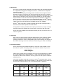
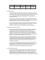
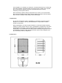
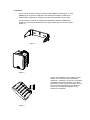
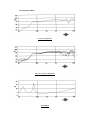
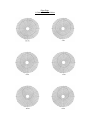
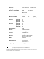
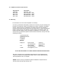
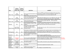
i5 AW & i5T AW USER MANUAL CONTENTS 1. Introduction 2. Unpacking 3. Connectors/Cabling 4. Polarity Checking 5. Amplification & Power Handling 6. Power Selection (i5T AW) 7. Equalisation 8. Dimensions 9. Hardware 10. Performance Data 11. Technical Specifications 12. i5 AW Recommended Service Parts & Accessories 13. Warranty 14. Declaration of Conformity 1. Introduction The Tannoy i5 AW has been designed to be both sonically and cosmetically pleasing for all applications ranging from background music in a restaurant to live keyboard monitoring on stage. TM ICT or Inductive Coupling Technology utilises a wireless electromagnetic tweeter that does not require a crossover and cannot be burned out from heavy or abusive use. The 1" aluminium high frequency dome has a deep drawn skirt which sits on the inside of the low frequency voice coil in the same magnetic gap. The skirt is like a single shorted turn, which is induced with high frequency information generated by TM the low frequency voice coil, which is fed a full bandwidth signal. The ICT dome is at the heart of our i5 AW transducer which utilises a moulded plastic cone and nitryl rubber surround to further enhance its' durability and long term reliability. TM The ICT driver is housed in a plastic enclosure that has been optimally tuned to achieve maximum bass response and tonal balance. For applications requiring extended low frequency enhancement, a range of Tannoy sub-bass systems are available and can be used in conjunction with the i5 AW. The i5 AW is also available as a Transformer version (i5T AW), for use from 70.7V or 100V line systems 2. Unpacking Every Tannoy i5 AW is carefully inspected before packing. After unpacking, please inspect for any exterior physical damage, and save the carton and any relevant packaging materials in case the loudspeaker again requires packing and shipping. In the event that damage has been sustained in transit notify your dealer immediately. 3. Connectors/Cabling The i5 AW has two spring-loaded terminals for connection to the amplifier. These terminals are capable of accepting cables with conductor diameter of up to 6mm. Red is Positive Black is Negative Cable choice consists mainly of selecting the correct cross-sectional area in relation to the cable length and the load impedance. A small cross-sectional area would increase the cables' series resistance, inducing power loss and response variations (damping factor). 2 Connectors should be wired with a minimum of 2.5 mm (12 gauge) cable. This will be perfectly satisfactory under normal conditions. In the case of very long cable runs the wire size should exceed this, refer to the following table for guidance: - CABLE RUN (m) C.S.A. OF EACH CONDUCTOR (mm) CABLE RESISTANCE Ω Ω % POWER LOSS INTO 8Ω Ω LOAD % POWER LOSS INTO 4Ω Ω LOAD 10 2.5 4.0 6.0 2.5 4.0 6.0 2.5 4.0 0.14 0.09 0.06 0.35 0.22 0.14 0.69 0.43 1.7 1.1 0.73 4.3 2.7 1.8 8.6 5.4 3.5 2.2 1.5 8.6 5.4 3.6 17.0 11.0 25 50 100 6.0 2.5 4.0 6.0 0.29 1.38 0.86 0.58 3.6 17.0 11.0 7.2 7.2 35.0 22.0 14.0 4. Polarity Checking It is most important to check the polarity of the wiring. A simple method of doing this without a pulse based polarity checker for the drive unit is as follows: Connect two ve ve wires to the + and - terminals of a PP3 battery. Apply the wire that is connected to ve the + terminal of the battery to the speaker cable leg which you believe to be ve connected to the red speaker terminal and likewise the - leg of the battery to the black speaker terminal. If you have wired it correctly the drive unit will move forward, indicating the wiring is ve ve correct. All that remains now is to connect the + speaker lead to the + terminal on ve ve the amplifier and the - lead to the - terminal on the amplifier. If however the driver moves backwards, the input connections need to be inverted. If problems are encountered, inspect the cable wiring in the first instance. It should also be noted that different amplifier manufacturers utilise different pin configurations and polarity conventions, if you are using amplifiers from more than one manufacturer, check the polarity at the amplifiers as well as the loudspeakers. 5. Amplification and Power Handling As with all professional loudspeaker systems, the power handling is a function of voice coil thermal capacity. Care should be taken to avoid running the amplifier into clip (clipping is the end result of overdriving any amplifier). Damage to the loudspeaker will be sustained if the amplifier is driven into clip for any extended period of time. Headroom of at least 3dB should be allowed. When evaluating an amplifier, it is important to take into account its behaviour under low impedance load conditions. A loudspeaker system is highly reactive and with transient signals it can require more current than the nominal impedance would indicate. Generally a higher power amplifier running free of distortion will do less damage to the loudspeaker than a lower power amplifier continually clipping. It is also worth remembering that a high powered amplifier running at less than 90% of output power generally sounds a lot better than a lower power amplifier running at 100%. An amplifier with insufficient drive capability will not allow the full performance of the loudspeaker to be realised. It is important when using different manufacturers amplifiers in a single installation that the have very closely matched gains, the variation should be less than +/- 0.5dB. This precaution is important to the overall system balance when only a single compressor/limiter or active crossover is being used with multiple cabinets; it is therefore recommended that the same amplifiers be used throughout. 6. Power Selection (i5T AW) Determine the maximum power in watts needed at each speaker location. The i5T AW transformer can be tapped at 30W, 15W, 7.5W and 3.5W via the rotary switch located at the front of the loudspeaker, at either 70 or 100-Volt lines. When the relevant tappings have been selected add the individual wattages required at all speakers and select an amplifier with a rating equal to or exceeding the total wattage required. All of the transformer primaries should be connected in parallel to the output of the amplifier. If for example, you select the 7.5 Watt transformer tap, it means that at full rated amplifier output the speaker will receive the full 7.5Watts. If the amplifier gain is reduced each speaker will receive a proportional amount of power, maintaining overall system balance. When calculating amplifier wattage requirements for a system, it is recommended that a generous wattage safety margin (3dB of headroom) be left so that the system does not have to operate continuously at its full rated output. 7. Equalisation The i5 AW is designed to need no equalisation or correction to overcome system limitations. As a result, it will only need equalisation to compensate for difficult acoustic environments. Excess equalisation can reduce system headroom, and introduce phase distortion resulting in greater problems than it cures. If equalisation is required then it should be applied gently and smoothly. Violent equalisation will be detrimental to the overall sound quality. If the loudspeakers were being used consistently at high levels it would be beneficial to introduce a high-pass filter at 50Hz to protect the loudspeaker from any unnecessary subsonic frequencies. 8. Dimensions 9. Hardware The i5 AW can be wall or ceiling mounted using the MB5Y bracket (Figure 1) or the MB5B (Figure 3). Both are designed to offer maximum flexibility in selecting the desired angles. Methods of mounting have been demonstrated in figures 2 & 3. For this product to conform to weatherproof specification IP33CS in EN60529 it should be mounted facing downwards at an angle greater than 35° from the vertical (Figure 3) Figure 1 Figure 2 NOTE: The installation of this product must be carried out in conformity with local building standards. If necessary consult your local safety standards officer before installing any product. Alternatively, check any laws or bylaws. Tannoy will not be held responsible for any damages caused by the improper installation of any bracket or loudspeaker. Figure 3 10. Performance Data Frequency Response Off Axis Frequency Response Impedance Polar Plots 1 Octave Band Pink Noise 11. Technical Specifications NOTES: System Type Vented, full range ICTTM loudspeaker system Frequency Response (1) +/- 3dB 80Hz-22kHz Sensitivity (1) 2.83 Volts @ 1m 90dB Impedance Nominal 6 Ω Minimum 3.8Ω Power Handling (2) Average (2) 50W Programme 100W Peak(10ms) 200W Maximum SPL (3) @1m Average Peak 107dB 113dB Average (half-space) 110dB DI Averaged @1kHz (ISO) @2kHz (ISO) @4kHz (ISO) @8kHz (ISO) @16kHz (ISO) 3.9 7.9 8.6 10.3 9.2 Q Averaged @1kHz (ISO) @2kHz (ISO) @4kHz (ISO) @8kHz (ISO) @16kHz (ISO) 2.5 6.1 7.2 10.7 8.3 93dB (half-space) Driver Complement 5" Enclosure 4.6litres, polypropylene Finish Charcoal grey, White Connectors 4mm Binding Posts Fittings Fixing points for MB5Y and MB5B brackets Dimensions 223.5(H)×162.6(W)×153.0(D)mm 8.81"(H)×6.41"(W)×6.03"(D) Weight 2.0kg (each) Accessories MB5Y and MB5B mounting brackets Shipping Dimensions 425×210×280mm 16.75"×8.27"×11.03" Shipping Weight 4.5kg (pair) (1) Average over stated bandwidth. Measured at 1m on axis, in an anechoic chamber. (2) Long term power handling capacity as defined in EIA standard RS - 426A. (3) Unweighted pink noise input, measured at 1m Tannoy operates a policy of continuous research and development. The introduction of new materials or manufacturing methods will always equal or exceed the published specifications which Tannoy reserve the right to alter without prior notice. Please verify the latest specifications when dealing with critical applications. 12. i5 AW Service Parts & Accessories Part Number 7900 0567 8001 1680 8001 1690 8001 1470 8001 1480 Description Driver Kit - 1273 MB 5Y Bracket - Black MB 5Y Bracket - White MB 5B Bracket - Black MB 5B Bracket - White 13. Warranty No maintenance of the i5 AW loudspeaker is necessary. All Tannoy professional loudspeaker products are covered by a 5-year warranty from the date of manufacture subject to the absence of misuse, overload or accidental damage. Claims will not be considered if the serial number has been altered or removed. Work under warranty should only be carried out by a Tannoy Professional dealer or service agent. This warranty in no way affects your statutory rights. For further information please contact your dealer or distributor in your country. If you cannot locate your distributor please contact Customer Services, Tannoy Ltd at the address given below. Customer Services Professional Division Tannoy Ltd. Coatbridge Scotland ML5 4TF Telephone: Fax: E-Mail: 01236 420199 +44 1236 420199 01236 428230 +44 1236 428230 [email protected] (National) (International) (National) (International) DO NOT SHIP ANY PRODUCT TO TANNOY WITHOUT PREVIOUS AUTHORISATION Our policy commits us to incorporating improvements to our products through continuous research and development. Please confirm current specifications for critical applications with your supplier. EASE Data for Tannoy Professional products available on request and from Tannoys' web site: http://www.tannoy.com 14. Declaration of Conformity The following apparatus is/are manufactured in the United Kingdom by Tannoy Ltd of Rosehall Industrial estate, Coatbridge, Scotland, ML5 4TF and conform(s) to the protection requirements of the European Electromagnetic Compatibility Standards and Directives relevant to Domestic Electrical Equipment. The apparatus is designed and constructed such that electromagnetic disturbances generated do not exceed levels allowing radio and telecommunications equipment and other apparatus to operate as intended, and, the apparatus has an adequate level of intrinsic immunity to electromagnetic disturbance to enable operation as specified and intended. Details of the Apparatus: Model Number: i5 AW Associated Technical File: EMCi5AW Applicable Standards: EN 50081-1 Emission EN 50082-1 Immunity Signed: Position: Electro-acoustics Development Engineer Tannoy Professional Date: 22/2/2000 For Tannoy Ltd Tannoy Loudspeakers are manufactured in Great Britain by : Tannoy Ltd, Coatbridge, Scotland. ML5 4TF. Telephone: +44 (0)1236 420199 Fax: +44 (0)1236 428230 Internet:http://www.tannoy.com TGI/Tannoy, 300 Gage Avenue, Kitchener, Ontario, CANADA, N2M 2C8 Telephone: (519) 745 1158 Fax: (519) 745 2364 Tannoy Nederland BV, Anthonetta Kuijistratt 19, 3066GS, Rotterdam THE NETHERLANDS Telephone: (015) 2124034 Fax: (015) 2125213 Tannoy is a member of the Group of Companies th ML 24 August 1999 Issue 1 Part No. 6481 0326