1
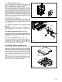
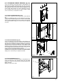
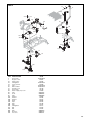
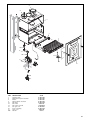
6.5 PUMP ASSEMBLY (fig. 21)
Carry out component removal procedure as described in 6.4.
Disconnect and remove the pump outlet pipe (A) from the
pump assembly/combustion chamber connection.
Remove the expansion pipe locking pin from the top of the
pump assembly and withdraw the flexible pipe. Locate and
remove the pressure gauge securing pin and disconnect the
pressure gauge from the pump assembly. Disconnect the
electrical wiring from the pump’s electrical connection point.
Locate and remove the 2 securing screws (E) at the rear of the
pump assembly. Remove locking pin (F) from pump base and
lift pump assembly clear of the hydraulic manifold. The pump
assembly can now be removed from the appliance. Replace
carefully in the reverse order.
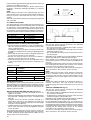
Fig. 20
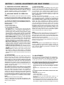
6.6 SAFETY VALVE (fig. 22)
Carry out component removal procedure as described in 6.4.
Disconnect the outlet pipe from the safety valve, remove safety
valve locking pin (H) from the hydraulic manifold. Replace in
the reverse order.
A
J
6.7 LOWER AUTOMATIC AIR RELEASE VALVE
(fig. 21)
M
N
Carry out component removal procedure as described in 6.4.
Rotate and remove the AAV assembly (J). Replace in the
reverse order.
6.8 WATER PRESSURE SWITCH (fig. 22)
Carry out component removal procedure as described in 6.4.
Locate and remove the locking pin (M) from the water pressure
switch (N). Remove the wiring. Carefully withdraw the switch.
Replace in the reverse order.
E
H
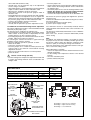
6.9 FLOW THERMISTOR (fig. 4 - pos. 10)
Carry out component removal procedure as described in 6.4.
Unclip and remove the air chamber front cover. Unclip the flow
thermistor from the flow outlet pipe. Disconnect thermistor
electrical plug. Replace in the reverse order.
F
Fig. 21
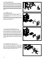
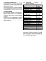
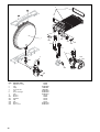
6.10 PRINTED CIRCUIT BOARD (fig. 23)
Carry out component removal procedure as described in 6.4.
Pull the control fascia forward and lower it. Push the clips (O)
which secure the PCB cover, remove cover, after carefully
taking note of all wiring connections and jumper tag configuration. Unhook and remove connection block. Disconnect all
wiring from the PCB, locate and remove the PCB securing
screws, remove the required PCB. Replace in the reverse
order ensuring that the position of the 2 control knobs are
correctly aligned with the respective potentiometers on the
PCB.
Ensure that the correct jumper tag configuration has been
respected. It will be necessary to check the functioning of the
PCB is set for the correct boiler type/application.
O
Fig. 23
19