1
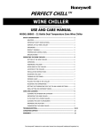
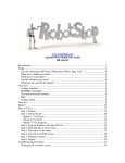
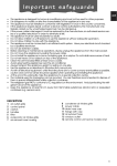
Maxi Rotators
Model No.
4631Q
4631 JPNQ
4631-1CEQ
4631-1CECN
057-092-00 • 11/ 05/ 11
Table of Contents
Description ..........................................................................................................................................................3
Safety Information ..............................................................................................................................................4
Alert Signals..................................................................................................................................................4
Specifications ......................................................................................................................................................5
Power Requirements ....................................................................................................................................5
Shaker Motion ..............................................................................................................................................5
Shaker Speed ..............................................................................................................................................5
Platform Dimensions ....................................................................................................................................5
Net Weight ....................................................................................................................................................5
Declaration of Conformity ............................................................................................................................6
Units Environmental Operating Conditions ..................................................................................................6
Unpacking and Installation ..................................................................................................................................7
Shipping Carton ............................................................................................................................................7
Unpacking ....................................................................................................................................................7
Electrical Requirements................................................................................................................................7
Location ........................................................................................................................................................8
Operation ............................................................................................................................................................9
Power Mains Protection..............................................................................................................................10
Maintenance ......................................................................................................................................................11
Neutralizing Spills........................................................................................................................................11
Relacing the Power Switch and the Speed Control....................................................................................11
Replacement Parts............................................................................................................................................12
Ordering Procedures ........................................................................................................................................13
Warranty ............................................................................................................................................................16
2
Description
The Maxi Rotator is a compact unit ideal for hybridization
blotting, staining and destaining gels, serological and
other laboratory procedures that require a smooth, consistent mixing action. With a bi-directional movement, the
mixing motion is a horizontal and vertical orbital rotation
through a 6º angle at speeds from 0 to 25 rpm.
The lightweight body makes for easy portability and its
compact size permits use in areas with limited space.
The non-skid platform surface holds containers in place
and the rotator's rubber feet provide stability.
3
Safety Information
Alert Signals
Warning
Warnings alert you to a possibility of
personal injury.
Caution
Cautions alert you to a possibility of
damage to the equipment.
Note
Notes alert you to pertinent facts and
conditions.
Hot Surface
Hot surfaces alert you to a possibility
of personal injury if you come in contact with a surface during use or for a
period of time after use.
4
Your Thermo Scientific Lab-Line Maxi Rotator has been
designed with function, reliability, and safety in mind. It is
your responsibility to install it in conformance with local
electrical codes. It is most important that the user follow
installation instructions exactly as written. Failure to do so
is likely to lead to improper operation, erroneous calibrations and possible damage to the equipment. Do not
attempt operation without this information.
Specifications
Power Requirements
Model
Model
Model
Model
4631Q:
4631 JPNQ:
4631-1CEQ:
4631-1CECN
120 VAC, 50/60 Hz, 0.4 Amps, 48 Watts
100 VAC, 50/60 Hz, 0.5 Amps, 48 Watts
220-240 VAC, 50/60 Hz, 0.2 Amps, 50 Watts
220-240 VAC, 50/60 Hz, 0.2 Amps, 50 Watts
Shaker Motion
A bi-directional movement, a horizontal and vertical orbital rotation through a 6° angle.
Shaker Speed
0 to 25 revolutions-per-minute.
Platform Dimensions
16”W x 14”D (41 x 36 cm)
13-1/8”W x 10”D x 4-3/16”H (33 x 25 x 11 cm)
Net Weight
14 lbs. (6 kg)
5
SPECIFICATIONS
Declaration of Conformity
(For 220 to 240 volt, CE models only)
We hereby declare under our sole responsibility that this product conforms with the technical requirements of
the following standards:
EMC:
EN 61000-3-2
EN 61000-3-3
EN 61326-1
Safety: EN 61010-1
EN 61010-2-051
Limits for harmonic current emissions
Limits for voltage fluctuations and flicker
Electrical equipment for measurement, control, and laboratory use;
Part l: General Requirements
Safety requirements for electrical equipment for measurement, control, and
laboratory use; Part I: General Requirements
Part II: Particular requirements for laboratory equipment for mixing and stirring
per the provisions of the Electromagnetic Compatibility Directive 89/336/EEC, as amended by 92/31/EEC and
93/68/EEC, and per the provisions of the Low Voltage Directive 73/23/EEC, as amended by 93/68/EEC.
The authorized representative located within the European Community is:
Thermo Fisher Scientific
419 Sutton Road
Southend On Sea
Essex SS2 5PH
United Kingdom
Copies of the Declaration of Conformity are available upon request.
Units Environmental Operating Conditions
Pollution Degree*:
Installation Category*:
Altitude:
Humidity:
Electrical Supply:
Voltage Tolerance:
Temperature:
Product Usage:
*Refer to IEC 664-1
6
2
II
2000 Meters MSL (Mean Sea Level)
80% maximum, non-condensing
120VAC or 240VAC
±10% of normal rated line
15ºC to 40ºC
This product is intended for use indoors only
Unpacking and Installation
Shipping Carton
This should be inspected upon delivery. When received,
carefully examine for any shipping damage before
unpacking. If damage is discovered, the delivering carrier
should both specify and sign for the damage on your copy
of the delivery receipt.
Open the carton carefully making certain that all parts are
accounted for before packaging materials are discardedafter unpacking, if damage is found promptly report it to
the carrier and request a damage inspection promptly.
IMPORTANT: Failure to request an inspection of damage
within a few days after receipt of shipment absolves the
carrier from any liability for damage: you must call for a
damage inspection promptly.
Unpacking
Use the packing list below when unpacking to verify that
the complete unit has been received. Do not discard packing materials until all is accounted for.
•
Operation Manual
•
Registration Card
•
•
Volt Warning-240V
Inspection Card
Electrical Requirements
Note
Leave rotator disconnected when not
in use.
120 VAC models require a 120 VAC, 50/60 Hz power
source. They are supplied with a 3-wire line cord. It
should be plugged into an outlet designed for 3-prong
plugs. If an extension cord is used, it also should be the
3-wire grounded type. For an outlet designed to accept 2prong plugs (ungrounded), it is required that a qualified
electrician replace the outlet with a new grounded type.
240 VAC models require a 240 VAC, 50/60 Hz power
source and are supplied with a European cord set.
7
UNPACKING AND INSTALLATION
Note
Position rotator so that in case of
emergency the plug is within easy to
be quickly disconnected from the
power outlet.
100 VAC models require a 100 VAC, 50/60 Hz power
source. Because of the variety of plug configurations in
use worldwide for 100 VAC power, the unit is furnished
with the plug removed. The user must install a plug to
conform with local code and configuration requirements.
If a plug must be installed, use only the 3-prong grounded
type, rated for the unit load requirements and matching
the power outlet. Make sure the green ground wire is
secured to the plug ground terminal.
Location
For optimum performance, place the unit on a level, stable
surface and in an area free from drafts, extraneous heat
sources and vibration. Be sure to provide clearance on all
sides so as to avoid contact of the moving platform with
any surrounding equipment or objects.
•
•
•
8
Do not use in a room with a temperature higher
than 40ºC.
Do not use in a room with a temperature lower
than 0ºC.
Do not use in a damp atmosphere.
Operation
ON
POWER
OFF
SPEED
POWER SWITCH
#440-359-00 (120V UNIT)*
#440-292-00 (240V UNIT)*
•
Check that the power switch is in the OFF position.
•
Place glass slides, microtiter plates and other vessels on the
platform. Arrange the materials so as to avoid any possibility
of contact with each other while the rotator is in motion.
•
Warning
Do not use in the presence
of flammable or combustible
materials or explosive
gases. Do not use in the
presence of pressurized or
sealed containers-fire or
explosion may result, causing death or severe injury.
SPEED CONTROL
#227-841-00 (SPEED CONTROL)*
#560-225-00 (KNOB)*
•
•
•
•
Note
If the equipment is used in a manner not specified by the manufacturer, the protection provided by the •
equipment may be impared.
•
Rotate the speed control to the 0 position.
Turn the power switch to the ON position.
Rotate the speed control to a point where the platform is just
moving. At this level of rotation, determine that the vessels
on the platform are secure and that no liquids are in danger
of escaping. Slowly increase the speed of rotation to the
level desired, continuing to observe that all materials are
secure.
In the event that gases may be emitted from any reactions
taking place, the rotator should be placed in a properly vented hood.
Observe all rules of your organization or laboratory regarding the wearing of safety gloves, glasses and protective
clothing.
After mixing action has completed, return speed control to 0
and turn unit off.
To lengthen life of unit, it is recommended that unit be disconnected from its power source when not in use.
*As listed on upcoming replacement parts list
9
OPERATION
Caution
Do not operate rotator without platform
in place. Exposed rotating parts can
be a hazard to fingers and/or clothing
such as shirt cuffs, ties, buttons and
similar items.
Note
This symbol means a high-power
warning; found on yellow warning
label on bottom of unit.
Caution
Protection provided by the equipment
may be impaired if not correctly used
in the manner specified.
10
Power Mains Protection
If a fuse blows, have a qualified person replace it with a
properly rated fuse. The internal primary of the transformer fuse is:
5 AMP, Littlefuse® #313.005, 3AG, Slo-Blo Type
(Thermo Scientific Part #330-273-00).
Maintenance
Note
Make no attempt to service or repair a
Thermo Scientific product under warranty before consulting your distributor. After the warranty period, such
consultation is still advised, especially
when the repair may be technically
sophisticated or difficult.
If assistance is needed beyond what
the distributor can provide, please call
the customer service department at 1800-553-0039. No merchandise, however should be returned without prior
approval.
Caution
Disconnect plug from electrical outlet
before attempting any maintenance or
repair of this unit.
Neutralizing Spills
In the event of any spills on the surfaces of the unit, carry
out appropriate neutralization procedures and/or wash off
with a cleaning solution made of warm water and a mild
detergent. Rinse off with clean water and dry thoroughly.
Do not use abrasive cleaners on surfaces.
Replacing the Power Switch and
the Speed Control
Replacing the power switch and/or speed control requires
removal of the bottom cover. Turn unit over and remove 4
screws holding the bottom cover and lift cover from the
housing.
•
Power Switch: Disconnect wiring from switch.
Grasp the switch on its top and bottom, depress
the locking spring sufficiently to free the switch
from the unit. Withdraw from the front. Reverse
procedure to install new switch.
•
•
•
Speed Control : Replace the speed control by
removing 2 setscrews and a retaining nut to
separate it from the panel. Disconnect the wiring
from the speed control and reconnect to the
replacement speed control.
Reverse the sequence to put speed control into
position on the panel.
Replace bottom cover and tighten the 4 screws
previously removed.
11
Replacement Parts
Description
Bearing
Bearing Housing
Circuit Breakers, 1 Amp (2)
Cordset (for 4631Q)
Cordset (for 4631-1CEQ)
Cordset, CE (Euro)
Fuse, 5 Amp
Knob
Power Switch, 100/120V Unit
Power Switch, 240V Unit
Mat, Vinyl
Motor
Rod End, Male
Rod End, Female
Rubber Feet (4)
Speed Control
Transformer, 240V Unit
Wiring Schematic, 100/120V Unit
Wiring Schematic, 240V Unit
Wiring Schematic, (4631-1CEQ)
Wiring Schematic, (4631-1CEQ)
12
Part Number
140-030-00
584-961-00
330-158-00
470-187-00
470-299-00
470-299-00
330-273-00
560-225-00
440-359-00
440-292-00
790-316-01
370-371-00
803-610-00
803-611-00
790-214-00
227-841-00
460-242-00
228-541-00
228-558-00
229-121-00
228-817-00
Ordering Procedures
Please refer to the Specification Plate for the complete
model number, serial number, and series number when
requesting service, replacement parts or in any correspondence concerning this unit.
All parts listed herein may be ordered from the Thermo
Scientific dealer from whom you purchased this unit or
can be obtained promptly from the factory. When service
or replacement parts are needed we ask that you check
first with your dealer. If the dealer cannot handle your
request, then contact our Customer Service Department
at 563-556-2241 or 800-553-0039.
Prior to returning any materials, please contact our
Customer Service Department for a “Return Materials
Authorization” number (RMA). Material returned without
an RMA number will be refused.
13
14
15
North America: USA/Canada +1 866 984 3766 (866-9-THERMO) www.thermo.com
Europe: Austria +43 1 801 40 0, Belgium +32 2 482 30 30, France +33 2 2803 2180, Germany
national toll free 08001-536 376,
Germany international +49 6184 90 6940, Italy +39 02 02 95059 434-254-375, Netherlands +31 76
571 4440, Nordic/Baltic countries +358 9 329 100,
Russia/CIS +7 (812) 703 42 15, Spain/Portugal +34 93 223 09 18, Switzerland +41 44 454 12 12, UK/
Ireland +44 870 609 9203
Asia: China +86 21 6865 4588 or +86 10 8419 3588, India toll free 1800 22 8374, India +91 22 6716
2200, Japan +81 45 453 9220,
Other Asian countries +852 2885 4613 Countries not listed: +49 6184 90 6940 or +33 2 2803 2180