1
www.robotshop.com
Adafruit Wave Shield User Guide
RB-Ada-04
Introduction......................................................................................................................... 3
FAQs ................................................................................................................................... 4
Can this shield play MP3 files? What about WMA, Ogg, AAC…?............................... 4
What sort of audio can it play? ....................................................................................... 4
What does it sound like? ................................................................................................. 4
Can this shield record audio?.......................................................................................... 4
What pins are used by the shield?................................................................................... 4
Overview............................................................................................................................. 5
Voltage regulator ............................................................................................................ 5
SD/MMC card holder ..................................................................................................... 5
The microcontroller/Arduino .......................................................................................... 6
DAC ................................................................................................................................ 7
Analog output.................................................................................................................. 8
Parts list............................................................................................................................... 9
Make it .............................................................................................................................. 12
How to Use it .................................................................................................................... 27
Step 1: Format............................................................................................................... 27
Step 2: Check the file.................................................................................................... 30
Option 1. Use iTunes ................................................................................................ 31
Option 2. Use SoX .................................................................................................... 33
Option 3. Use Audacity............................................................................................. 33
Step 3. Start up Audacity and open the file .................................................................. 34
Step 4. Split and Mix a stereo track .............................................................................. 36
Step 5. Convert to 16 bit audio ..................................................................................... 37
Step 6. Convert to 22-KHz or less ................................................................................ 38
Step 7. Prepare to export............................................................................................... 38
Step 8. Export! .............................................................................................................. 39
Troubleshooting & Extras................................................................................................. 41
Getting Stack overflow errors? ..................................................................................... 41
Get more RAM & Flash! .............................................................................................. 41
Generating speech......................................................................................................... 41
Sound sample library .................................................................................................... 41
Digital audio player....................................................................................................... 41
PI party! ........................................................................................................................ 41
Sample Code ..................................................................................................................... 42
Introduction
The shield comes with an Arduino library for easy use; simply drag uncompressed wave
files onto the SD card and plug it in. Then use the library to play audio when buttons are
pressed, or when a sensor goes off, or when serial data is received, etc. Audio is played
asynchronously as an interrupt, so the Arduino can perform tasks while the audio is
playing.
•
•
•
•
Can play any uncompressed 22KHz, 16bit, mono Wave (.wav) files of any size.
While it isnt CD quality, it is certainly good enough to play music, have spoken
word, or audio effects
Output is mono, into L and R channels, standard 3.5mm headphone jack and a
connection for a speaker that is switched on when the headphones are unplugged
Files are read off of FAT16 formatted SD/MMC card
Included library makes playing audio easy
While the shield has been tested and works well, here are some points to keep in mind
The audio playback library uses 10K of flash - so if you want to use an NG
arduino, you'll need to upgrade to an Atmega168 chip
• About 600 bytes of SRAM are used to buffer the audio and keep track of file data,
so RAM-heavy projects may not work well
• The shield can't play MP3, WMA, Ogg or other compressed audio files. It can
only play uncompressed PCM/WAV files. Converting audio to WAV format is
very easy, and is often the default format for many audio programs.
• Files are stored as 8.3 name format, and can only be placed in the root directory.
That means you can only have ~512 files (but they can be any size).
Ideas for what you can use it for.
•
•
•
•
•
•
•
•
•
•
•
•
•
Make a portable audio player
Use the AT&T text-to-speech site to make snippets of speech that you string
together for a talking project, like..
Talking temperature sensor
Talking clock
Interfaces for sight-impared people
Doorbell that plays a cool tune
Jukebox/music-box that plays a song when its opened, or a coin is inserted
Security system that warns the intruder
Audio looper for musical effects and performances
Synthesizer with different sounds
Really freaky halloween props that scream
Display (like a point-of-sale box) that you can plug into to hear the message
FAQs
Can this shield play MP3 files? What about WMA, Ogg, AAC…?
No, compressed audio requires either a specialized chip (which is expensive) or a very
powerful chip. The Arduino microcontroller can't uncompress MP3 on the fly and to keep
the shield inexpensive, no mp3 decoder chip is included.
What sort of audio can it play?
It can play uncompressed Wave files (.wav format). This is a standard format and pretty
much every audio program can convert your music or audio into wave format. Make sure
the sample rate is mono, 22KHz (or less) and 16-bit (or less).
What does it sound like?
The best way to determine if the quality is good enough for your project is use Audacity
and go thru the steps in the User Manual for converting MP3s (and other files) to
22KHz/16-bit format.
Can this shield record audio?
There is no hook-up for a microphone, so there is no easy way to record audio. There is
also not enough program space on the current Arduino chips (atmega168) to support
recording audio and saving it to the SD card as well as playback.
What pins are used by the shield?
Pins 13, 12, 11 are always used by the SD card (they are the only pins that have a high
speed SPI interface). Then there are 5 other pins used to talk to the DAC and SD card, but
they can be set to connect to any arduino pin. However, by default, the library is
configured to use pins 10 (for SD card) and pins 2, 3, 4 and 5 for the DAC. To chanage
these pins requires modifying the library - the pins are referenced by their 'hardware' pin
names (ie PORTD, etc) not by arduino pins. That means pins 6, 7, 8, 9 and the 6 analog
in pins (also known as digital i/o pins 14-20) are available
Overview
Here is an explanation of how the wave shield works. We'll go section by section. You'll want to refer
to the schematic
Voltage regulator
The easiest thing to understand is the 3.3V voltage regulator. This takes the 5V supply from the
Arduino and converts it to a nice 3.3V supply. This is necessary because SD/MMC cards only work
on 3.3V. If you give them 5V they'll burn out & die!
The voltage regulator used is the MCP1700-330, which can provide up to 250 mA of current. There
are 4 capacitors associated with the regulator. C1 and C2 are the input capacitors; they stabilize the
5V input. C3 and C4 are the output capacitors, they stabilize the 3.3V output
There is a jumper that allows you to skip the regulator and use the 'built in' 3.3V supply from the
Arduino. However, it is not suggested as that supply is not guaranteed to provide the current
necessary.
SD/MMC card holder
SD/MMC cards are very popular, small, and inexpensive. The card holder is what allows you to
remove and replace the card easily. They can be removed/replaced thousands of times. The top three
'pins' are CD, WP and COMMON_SW. CD stands for "card detect" this is a mechanical switch that
closes when the card is inserted. WP stands for "write protect", this is a mechanical switch that closes
when the card has the little side tab slid down to 'lock'. COMMON_SW is the common connection for
the two switches. We simply connect this to ground. Thus CD and WP will be grounded when active
At the bottom are the power supplies. There are 2 mechanical ground connections and a logic ground.
There is also the logic power connection, connected to the 3.3v regulator
In the middle are the data connections. DAT1 and DAT2 are for advanced/high-speed SD card
interfacing. We don't do this so they are left disconnected. DATA_OUT is the serial data out from the
card, which is connected to the SPI port of the Arduino. DATA_IN is the input and SCLK is the
clock input. Since they must be 3.3V and the Arduino usually sends 5V data, we use voltage dividers
(R2, R3, R4 and R5) to reduce the inputs down.
CS is the select line, used to tell the MMC that we want to send it data. This line is pulled low (to
ground) when we want to send data to the card. That means we need to make sure when we don’t have
anything connected, the pin is pulled high to ~3.3V. We use R6 as the pull-up and zener diode D1 to
keep the voltage at 3.3V. R1 allows the diode to bias properly when the Arduino pulls the pin high.
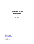
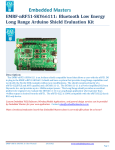
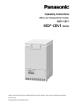
The microcontroller/Arduino
The library contains a bunch of specialized code. The first part is a 'FAT16' library, this is a set of
functions that allow the chip to read the SD card, locate files and read their contents. The method it
does this by is particularly detailed and you can read the SD/MMC and FAT16 manuals if you're
interested
Image stolen from Microsoft. Take that, Bill!
Once it opens a file and is ready to read it, it looks through the first section of the file. If it's a Wave
file, there will be all sorts of information stored in this header that will indicate the channels
(mono/stereo/etc), bits-per-sample (8 to 32), sample rate (ie 16KHz) etc. Basically, the firmware
verifies that it is mono channel, 16 or less bits-per-sample and 22KHz or less sample rate. Then it sets
up the audio interrupt that will go off sample-rate times a second. For example, if its a 22KHz audio
sample, the interrupt will go off 22,000 times a second!
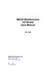
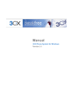
Image from wikipedia
The audio is encoded in PCM format. This means "pulse Code Modulation". Lets say its a 16bit,
22khz wave. The audio waveform is sliced up 22,000 times a second and a corresponding value (up to
16 bits - from 0 to 65,635) is read from the waveform, then that value is stored in the file. Each sample
is a unique value. The file is not compressed. This means the files are very large but the quality is very
very good.
The SD card can provide 512 bytes at a time. This is buffered inside the Arduino's RAM so that we
have smooth playback. (Techinally, its a double-buffer which means we read 256 bytes and play 256
bytes, then swap.) The audio interrupt picks one sample at a time and sends the data to the DAC
(digital/analog converter)
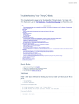
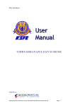
DAC
The DAC is a very simple device. When you send it data it will convert that digital information back
into an analog signal!
You'll notice it actually doesn't get the orignal waveform perfect. The more bits of digital data, the
higher quality of audio reproduction. CDs have 16-bits per sample. While it would have been nice to
have a 16-bit DAC, the best option for this design was a 12-bit dac. (That's still quite good.)
The microcontroller/Arduino uses the DAC_CS (chip select), DAC_CLK (data clock), DAC_DI
(data), and DAC_LATCH (convert the digital to analog) pins to send the sample data over. The DAC
also has a Vref input, this is the reference voltage that it uses to define the maximum analog value it
can generate. There is a very low low-pass filter connected to it (C6 and R8) so that any digital noise
(there is -a lot-) will not make it into the audio signal.
There is another low-pass filter connected to the output of the DAC (R7 and C8). This is for filtering
out the 'square wave' component you see in the recreated-audio wave. Even though the noise is only
1/4096'ths of the signal (about 1.2mV) its still noise and these two components filter out anything
above 11KHz. The reason the filter cut-off frequency is 11KHz and not 22KHz is that if you sample at
22KHz you will only be able to reproduce frequencies at half that rate, 11KHz. This is the Nyquist
theory. It is sneaky but true. If you try to sample 16KHz waveform at 22KHz it will actually sound
much -lower-, it will play at 6KHz (it is 'mirrored' around 11KHz)
Analog output
Finally there is the volume control and output stage. The potentiometer acts as a simple volume
control. It simply divides down the analog signal from 5Vpp down to as low as 0Vpp. The pot is
'audio' type which means that the voltage changes logarithmically, which our ears interpret as linearly.
The analog signal then goes into a high-output, rail-to-rail opamp. This op-amp can provide up to
100mA per channel. The two channels are hooked up in parallel for up to 200mA output (at 5V). This
means it can provide 1/8 W into an 8ohm speaker (or 1/4 W into 4ohm speaker). This isn't enough for
a boom-box but its good for headphones and small speakers. The output is filtered through a bypass
capacitor C9 which will keep any DC voltage from going to the speaker, which could damage it.
The headphone jack is stereo, which both mono channels connected in parallel. This gives the most
power output. There are internal switches in the jack so that when the headphones are removed, the
audio flows to the 'speaker connection' next to the jack.
Parts list
Check to make sure your kit comes with the following parts. Sometimes we make mistakes so double
check everything!
Image
Name
Description
Part # &
Datasheet
IC1
3.3V linear
voltage
regulator,
250mA
current
MCP1700- Digikey
3302E/TO Mouser
1
IC2
12-bit DAC
MCP4921
Digikey
Mouser
1
IC3
High-current
opamp
TS922IN
Digikey
or
Mouser
TS922AIN
1
SD/MMC
card holder
Tyco
Digikey
1734234-1
1
Distributor Qty
TM1
10K Audio
thumbwheel
potentiometer. 311Includes pot, 1204Fthumbwheel
10K
and tiny
screw
X1
Stereo
headphone
jack with
switches
Mouser
1
STX3100-5N
Mouser
or
Digikey
STX3100-5NB
1
R1
1/4W 5%
1.0K resistor
Brown Black
Red Gold
Digikey
Mouser
1
R7
1/4W 5%
1.5K resistor
Brown Green
Red Gold
Digikey
Mouser
1
1/4W 5%
R3,
4.7K resistor
R5, R6 yellow purple
red
Digikey
3
1/4W 5% 10K
resistor
R2, R4 Brown,
Black,
Orange, Gold
Digikey
Mouser
2
Digikey
1
R8
1/4W 5%
100K resistor
Brown,
Black,
Yellow, Gold
C8
0.01uF
ceramic
capacitor
(103)
May look
deceptively
like the 0.1uF
ceramic
capacitors!
Lately has
been shipped
in an 'axial'
(not 'radial'
package. See
instructions
for details.
1
0.1uF ceramic
capacitor
(104)
C2,
Looks
C3,
deceptively
C5,
like the
C6, C7
0.01uF
ceramic
capacitor!
Digikey
Mouser
5
C1,
100uF / 6V
C4, C9 capacitor
Digikey
Mouser
3
D1
3.6V Zener
diode
1N5227B
Digikey
Mouser
1
RESET
6mm tactile
switch
B3F-1000
Digikey
Mouser
1
ICSP
PCB
6-pin ICSP
header
Digikey
Mouser
1
36 pin male
header (1x36)
Digikey
Mouser
1
Circuit board
Adafruit
Industries 1
RobotShop
Make it
Get ready by placing the PCB in a vise
We're going to the SD card first. While surface
mount parts are a little tougher than thru-hole,
this piece has pin spacing of 0.1" so it is quite
easy. Doing it first also gives us lots of working
room. The holder should 'snap' perfectly into
place thanks to two bumps on the bottom.
We'll start with the four side tabs that are used to
mechanically secure the card holder in place.
Heat up the metal tab and the pad (the silver
square beneath it) for 3 seconds with a hot
soldering iron, then poke just a bit of solder in.
Do this for all three corners. Once this is done
you should not be able to lift the card holder
Now go thru and solder the 8 leftmost pins that
stick out from the holder. The three rightmost
pins are thinner and closer together so they are
tougher to solder. Luckily they are not used and
you simply skip them (although the photo shows
them done). Check that you have no solder
bridges - the pins should not be soldered to the
metal body of the holder or to each other
Next, we will solder all of the many resistors. The
10K resistors R2 and R4 are first. Form them into
staples (as shown left with a 100 ohm resistor),
then place them so they sit flat against the PCB,
in the correct locations. Resistors don't have
polarity so they can go in 'either way' and work
fine! Once placed, bend the leads out so the
resistors dont fall out. If you're using an NG
Ardiuno, replace R2 with a 1.0K-2.0K resistor
Solder the leads to the pads (metal ring) by
heating both with the side-tip of the iron for 3
seconds and then poking in a bit of solder
Use your diagonal cutters to clip the leads off just
above the solder joint
Next place the three 4.7K resistor R3 R5 and R6.
Make sure they go in the right locations! If you're
using the shield on an NG arduino, use a piece of
wire instead of R5
Solder and clip the leads of the three resistors
Finish up the resistors by placingR8 (100Kohm),
R1 (1.0K) and R7 (1.5K). In the photo, R1 is
shown as 1.5K...this is a mistake! (It was too
flakey for me and I reduced the resistance). Make
sure you place a 1.0K resistor in R1! Solder the
components
Next comes the 3.6V zener diode. A diode is sort
of resistor-shaped except that it has a black stripe
on one end. Diodes are polarized and must be
placed the correct way to work so make sure that
the black stripe on the diode matches the white
stripe on the silkscreen position indicator
Next is the 0.01uF ceramic capacitor C8. The
tricky part here is that in older kits there are many
0.1uF ceramic capacitors in the kit that look
identical to the 0.01uF!
The way to tell the difference is look for the 103
printed on it. If it says 104 then it's a 0.1uF. Make
sure it says 103! This capacitor forms the output
low-pass filter for the audio so its important to
have the right value.
Lately I have been shipping kits with axial (longways) package, not radial (side-ways) package.
These are longer (see left) and are easy to bend
over for soldering. This way there is less
confusion. Either way, try to spot the 103
marking
Place the capacitor right next to R7.
Ceramic capacitors are non-polarized and can go
in 'either way'
Solder and clip the small capacitor leads
Once you're sure you have C8 correct, you can
place the remaining 0.1uF ceramic capacitors C2,
C3, C5, C6 and C7.
Ceramic capacitors are non-polarized and can go
in 'either way'
Solder and clip the capacitors
Next is the DAC (digital-analog converter) IC2.
This is what turns the data into music. Make sure
you pick the DAC to solder in here; it says
MCP4921 on it and has a stylized M.
The chip has a notch in one end and that notch
must line up with the notch in the silkscreen. In
this photo, that’s on the right.
Flip over the board and solder in each pin of the
chip. The pins are already quite short so you
don’t have to clip them
Next is the operational-amplifier (op-amp) IC3. It
is used to buffer and amplify the output, so that it
can drive a small speaker or headphones.
This is a similar-looking chip to the DAC. Again,
check that the notch matches the silkscreen notch.
In this photo, that’s to the left. Solder it in, just
like you did with the DAC
Next is the 3.3V regulator IC1 that provides a
nice power supply to run the SD card. The
regulator comes in a semi-circular package, so
make sure it matches up with the silk-screened
image.
Turn the board over and solder/clip the three
leads.
Next is the reset button and the ICSP header.
These let you reset the Arduino manually, and
reprogram it directly with a AVR programmer.
The button will snap in, it’s symmetric so it goes
in 'either way'. The header is also symmetric,
make sure the long end sticks up
Solder in both components. Their leads are pretty
short so you don’t need to clip them.
Next are the three electrolytic capacitors C1 C4
and C9.
Electrolytic capacitors are polarized so make sure
they go in the right way! The long lead is the
positive lead, make sure that goes into the hole
marked with a + as shown here.
If you're planning to stack another shield on top
of this one, you may want to bend the capacitors
so they lay flat.
Next is the headphone jack. It snaps into place
right at the edge of the PCB.
Solder the jack in place. You may want to clip the
legs a little if you can, so that it will sit better on
the Arduino.
Next is the volume potentiometer TM1. This is an
audio-type 10K pot. It will slip into place pretty
easily.
Solder all 5 pins of the potentiometer. Use plenty
of solder so that it has a lot of mechanical
strength
Next, break the 36-pin header strip into smaller
sections so that the shield can be placed on the
Arduino. You can use pliers or diagonal cutters.
Clip off 2-6pin and 2-8pin pieces.
If you're using a Diecimila Arduino, place the 6
and 8 pin headers into the female sockets.
If you have an NG Arduino, you can place a 3pin female header (not included) as shown, which
will let you use the reset button.
Place the shield PCB onto the Arduino so that all
the holes match up with the header.
Solder in each and every pin of header
Next you can install the thumbwheel. Use a #0
screwdriver. Align the thumbwheel so it 'grabs'
the potentiometer, and then gently screw it in
place.
Pins 13, 12 and 11 are used to talk to the SD card
and can’t be changed. The rest of the pins,
however, are more flexible. Still, for all the
examples on the site we'll be using this wiring, so
it is suggested to just go with this.
You can use any sort of wire. Solder the jumper
wires in place.
Hooray you are done! Now onto the user
manual...
How to Use it
Introduction
The wave shield uses SD/MMC cards. They are extraordinarily popular, sometimes even
available in grocery stores! They are used in MP3 players, cameras, audio recorders, etc.
You can use any card that can store 32 MB to 1.0 GB. A 1 gigabyte card can hold 380
minutes of uncompressed audio for the shield, and costs $5
You'll also need a way to read and write from the SD card. Sometimes you can use your camera and
MP3 player - when its plugged in you will be able to see it as a disk. Or you may need an SD card
reader
Step 1: Format
The wave shield needs the SD card to be formatted in FAT16 format
To format the card, place it into your card reader, then right click on the disk and select Format...
Make sure that in the File system pulldown menu, that FAT is selected and not FAT32
And click Start
If you get the Properties of the card you will see it is FAT formatted. This card has some files on it so
its not completely empty
Intro
The wave shield is designed to play a very specific type of audio. If your music sample is in MP3
format, or 44KHz wav, you'll want to convert it to the right format. This way you will get the highest
quality audio
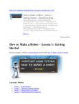
Step 2: Check the file
If you have a wave file already, you should check to see if its already in a proper format. That way
you will save yourself some time! In windows, right-click on the file, and select Properties then click
on the Summary tab
This file is 16KHz, 16-bit, mono PCM. Since thats below the maximum (22KHz, 16-bit, mono PCM)
you are good to go. No need to convert the file
OK lets say the file is an MP3 or 44KHz or stereo wave file. We will need to convert it down.
Option 1. Use iTunes
You can do the conversion easily with iTunes (available for Mac/Windows) if you have your music in
iTunes already this will be super fast to convert multiple files!
You'll have to set the preferences first, but you only have to do it once
Go to the Advanced->Importing tab. Make sure it is set to 22KHz (or less), 16bit (or less) and Mono
channels. Click OK
Next find the files you want to convert. Select Convert Selection to WAV from the menu
Then simply drag the sounds onto an SD card
Option 2. Use SoX
Option 3. Use Audacity
If you dont have or don't want to use iTunes you can convert files (one at a time) with Audacity
This is pretty easy. You can use the free Audacity software - available for windows, linux or mac
Grab it from the download page and install it on your computer
Step 3. Start up Audacity and open the file
Start up Audacity
Select File->Open... and open the file. In my case its an MP3
Audacity will spend some time uncompressing and opening the file and then present you with
something like this
Step 4. Split and Mix a stereo track
Next, if you have a stero track, you'll probably want to turn it into a mixed mono track. That way it
will sound most like the original. Click on the title and select Split Stereo Track
Next, when you mix a track you'll end up adding both of them together. This means that if both sides
are loud, you'll get distortion. Reduce the gain on both tracks to -6dB
Then convert both tracks to Mono by clicking on each title. Make sure you do it for both tracks!
Now to mix! From the menu select Project -> Quick Mix
A few seconds later, you have converted your stereo track to mono!
Step 5. Convert to 16 bit audio
If your audio rate is higher than 16-bit, you will want to downconvert it. Click on the track title and
select Set Sample Format -> 16-bit
Step 6. Convert to 22-KHz or less
Finally, make sure the audio file will be saved as 22KHz. If the the track label says 44KHz you will
want to convert it.
At the bottom of the window there is a little button named Project rate: Make sure this is 22KHz or
less
Step 7. Prepare to export
Check the Preferences menu item and select the File Formats tab. Make sure the Uncompressed
Export Format is WAV (Microsoft 16 bit PCM)
You only have to do this once!
Step 8. Export!
Finally, you're ready to export the file. Select Export as WAV... from the pulldown
It may take a few seconds to convert and save the file
Finally, check the file Properties. It should be 16 bit, mono, 22KHz (or less) and PCM format
OK! Now you can go to the next step, which is formatting an SD card and copying files over
Troubleshooting & Extras
Getting Stack overflow errors?
These examples are all tested to work with v13 or higher, so try to use that if possible!
Get more RAM & Flash!
Before you try to play audio, you'll want to free up some Arduino RAM, so that you don't
end up with a nasty stack-overflow. Especially if you're running a Atmega168-based
Arduino!
Follow these instructions on how to get more RAM by reducing the input Serial library
buffer. You dont need to do this if you're using an ATmega328 (although, hey it wont
hurt!)
Note that the library is pretty big (about 10K) so if you want to do a lot more, I suggest
upgrading to an ATmega328. The shield was designed with the expectation that this part
would be available.
Generating speech
If you want a human voice in your project, you can use the free generator at AT&T Textto-Speech demo page. It will create a 16KHz, 16-bit audio file so you can use the audio
'right out of the box'
http://www.research.att.com/~ttsweb/tts/demo.php#top
Sound sample library
There is huge a collection of C.C available online. Attribution licensed sound samples! A
lot of it is already mono, 16 or 22KHz
http://wiki.laptop.org/go/Sound_samples
Digital audio player
This is the simplest example. It plays every audio file it finds on the SD card in a loop. This sketch is
also included in the library
PI party!
This example shows how to use the AT&T text-to-speech website to speak the first 2640 digits of pi.
The number is stored in flash, each digit is spoken one at a time.
Sample Code
#include
#include
#include
#include
<AF_Wave.h>
<avr/pgmspace.h>
"util.h"
"wave.h"
AF_Wave card;
File f;
Wavefile wave;
// only one!
#define redled 9
uint16_t samplerate;
void setup() {
Serial.begin(9600);
// set up Serial library at 9600 bps
Serial.println("Wave test!");
pinMode(2, OUTPUT);
pinMode(3, OUTPUT);
pinMode(4, OUTPUT);
pinMode(5, OUTPUT);
pinMode(redled, OUTPUT);
if (!card.init_card()) {
putstring_nl("Card init. failed!"); return;
}
if (!card.open_partition()) {
putstring_nl("No partition!"); return;
}
if (!card.open_filesys()) {
putstring_nl("Couldn't open filesys"); return;
}
if (!card.open_rootdir()) {
putstring_nl("Couldn't open dir"); return;
}
putstring_nl("Files found:");
ls();
}
void ls() {
char name[13];
int ret;
card.reset_dir();
putstring_nl("Files found:");
while (1) {
ret = card.get_next_name_in_dir(name);
if (!ret) {
card.reset_dir();
return;
}
Serial.println(name);
}
}
uint8_t tracknum = 0;
void loop() {
uint8_t i, r;
char c, name[15];
card.reset_dir();
// scroll through the files in the directory
for (i=0; i<tracknum+1; i++) {
r = card.get_next_name_in_dir(name);
if (!r) {
// ran out of tracks! start over
tracknum = 0;
return;
}
}
putstring("\n\rPlaying "); Serial.print(name);
// reset the directory so we can find the file
card.reset_dir();
playcomplete(name);
tracknum++;
}
void playcomplete(char *name) {
uint16_t potval;
uint32_t newsamplerate;
playfile(name);
samplerate = wave.dwSamplesPerSec;
while (wave.isplaying) {
// you can do stuff here!
delay(500);
}
card.close_file(f);
}
void playfile(char *name) {
f = card.open_file(name);
if (!f) {
putstring_nl(" Couldn't open file"); return;
}
if (!wave.create(f)) {
putstring_nl(" Not a valid WAV"); return;
}
// ok time to play!
wave.play();
}