1
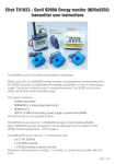
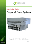
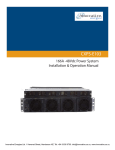
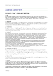
User Manual
Flatpack 1U Power Shelf with Rear Covers
Consists of:
Flatpack 1U PR Nortel Critical Connections Guide (B - 1503418 - 1)
Operation Guide 1.5mm FP PR w-covers (B - IM505393 - 1)
IM505394
Issue 1
August 2004
Flatpack Installation / Operation
Critical Connections Guide
1U Power Rack (Nortel)
This Guide is intended as supplemental documentation, always refer to the full
System Installation and Operation Guides for detailed startup information
AC Input Termination Points
AC Cover Removal
Important!
Before installing rectifiers:
AC Input Voltage Requirements
Rear of Rectifier Mounting Shelf
The Flatpack rectifier will operate from 85 – 310 VAC.
The output power of the rectifier is dependant on the
AC input range. 120 VAC nominal will produce 600W
Maximum. 208 / 220 / 240 VAC nominal inputs will
produce 1200 W Maximum.
AC Input Feed Sizing
AC Input- One Feed Per Shelf (2 rectifiers each shelf)
Input VAC Max AC Amps Feed Breaker Wire Size Output Watts
120
208
220
240
11.6
13.0
12.0
11.1
15A
20A
15A
15A
#14 AWG
#12 AWG
#14 AWG
#14 AWG
1200 W
2400 W
2400 W
2400 W
DC Distribution Terminations
Termination Studs are 10-32; torque to 21-31 In-Lb.
Load Rtn Bus
(+)
Hot Bus
(-)
Eltek Energy LLC. 115 Erick Street Crystal Lake, IL, 60014
Phone: (815)-459-9100. Fax: (815)-459-9118
Service / Spares: (800)-435-4872 International (815)-479-6082
Website: http://www.eltekenergy.com
Document Number 1503418
Rev 1, August 2004
Flatpack Installation / Operation
Critical Connections Guide
1U Power Rack (Nortel)
This Guide is intended as supplemental documentation, always refer to the full
System Installation and Operation Guides for detailed startup information
Alarm Output Terminations
Con3 – Con5: will accept wire #22 to #18 AWG
Form “C” Contacts Standard
For standalone applications, the power rack has
an alarm relay output. This will allow the user to
monitor the rectifier alarms without the addition
of an MCU. A relay opening or closure can be
used, depending on the application. The
connection is made to a 3-position terminal block
on the rear of the shelf.
Basic Settings
Setting The System Output Voltage
The Flatpack 1500 has a front accessible potentiometer that can be used to adjust the output voltage of the rectifier.
If more than one rectifier is to be installed in the system, it is advisable to install and adjust each rectifier individually turn
so that there is only one rectifier in the system at any one time, on completion all the rectifiers may then be installed.
This adjustment is normally set at the factory during
testing. It is advisable to avoid making un-necessary
re-adjustments, due account should be taken of the
effect this procedure may have on the customers
equipment.
Eltek Energy LLC. 115 Erick Street Crystal Lake, IL, 60014
Phone: (815)-459-9100. Fax: (815)-459-9118
Service / Spares: (800)-435-4872 International (815)-479-6082
Website: http://www.eltekenergy.com
Document Number 1503418
Rev 1, August 2004
Operation Guide
Flatpack 1U Power Shelf
with Rear Covers
IM505393
Issue 1
August 2004
Information in this document is subject to change without notice and does not represent a commitment on
the part of ELTEK Energy.
No part of this document may be reproduced or transmitted in any form or by any means — electronic or
mechanical, including photocopying and recording — for any purpose without the explicit written
permission of ELTEK Energy.
Copyright ©: ELTEK Energy, Norway 2004
Corporate Headquarters:
ELTEK Energy AS
P.O. Box 2340 Strømsø
N-3003 DRAMMEN
Norway
Phone: +47 32203200
Fax: +47 32203210
Americas Region Headquarters:
ELTEK Energy LLC
115 Erick Street
Crystal Lake, Illinois 60014
USA
Phone: +1 (800) 447-3484
Phone: +1 (815) 459-9100
Sales FAX: +1 (815) 459-9118
24-hour domestic service helpline +1 (800) 435-4872
24-hour international service helpline +1 (815) 479-0682
Service FAX +1 (815) 459-0453
Visit our Web site on the Internet:
http://www.eltekenergy.com
IM505393 Issue 1, August 04
This document was produced using Microsoft Word 9.0
dmh August 2004
Operation Guide, Flatpack 1U Power Shelf
IM505393 July 2004
2(12)
1
SCOPE..................................................................................................................................................................4
2
INSTALLATION PROCEDURES ....................................................................................................................4
2.1 SAFETY PRECAUTIONS ...................................................................................................................................4
2.2 MECHANICAL INSTALLATION.........................................................................................................................4
2.3 MAINS CONNECTIONS ....................................................................................................................................5
2.4 DC CONNECTIONS ..........................................................................................................................................8
2.5 ALARM CONNECTION .....................................................................................................................................9
2.5.1
Alarm conditions .....................................................................................................................................9
2.6 CONNECTIONS FOR COMMUNICATION .........................................................................................................10
3
SYSTEM OPERATION ...................................................................................................................................10
3.1
4
GENERAL ......................................................................................................................................................10
MECHANICAL DATA.....................................................................................................................................11
4.1
4.2
MECHANICAL DIMENSIONS ..........................................................................................................................11
MECHANICAL DRAWINGS ............................................................................................................................11
FIGURE 1 - AC COVER REMOVAL.........................................................................................................................6
FIGURE 2 - MAINS CONNECTIONS - FLATPACK POWER SHELF....................................................................6
FIGURE 3 - DC COVER REMOVAL.........................................................................................................................8
FIGURE 4 - ALARM OUTPUT CONNECTION........................................................................................................9
FIGURE 5 - COMMUNICATION INTERFACE - FLATPACK POWER SHELF..................................................10
TABLE 1 - WIRE SIZES FOR MAINS CONNECTIONS..........................................................................................5
TABLE 2 - PIN CONFIGURATION FOR MAINS CONNECTIONS .......................................................................6
TABLE 3 - MAINS CONFIGURATION FOR FLATPACK POWER SHELF ..........................................................7
TABLE 4 – AC INPUT WIRE SIZES AND FUSE / BREAKER RATINGS .............................................................7
TABLE 5 - ALARM CONDITIONS ...........................................................................................................................9
PROCEDURE 1: MECHANICAL INSTALLATION FLATPACK 1U PR................................................................5
PROCEDURE 2: MECHANICAL INSTALLATION FLATPACK 2U MCU PANEL..............................................5
PROCEDURE 3 - DC CONNECTIONS......................................................................................................................8
Operation Guide, Flatpack 1U Power Shelf
IM505393 August 2004
3(12)
1 Scope
This User Manual describes the Flatpack 1U power shelf with two Flatpack 1500 rectifiers installed. Each
rectifier can supply 1400W of output power making the total power from the Flatpack 1U Power Shelf 2800W.
The Flatpack 1U Power Shelf is designed for mounting into 19” cabinets. It is supplied as a stand-alone unit and
can be mounted into equipment. Extenders are supplied for installing the Flatpack 1U Power Shelf into ETSI racks
or 23” racks.
This Operation Guide contains an overview of the power shelf and its connections, together with a description of
it’s installation and commissioning.
2 Installation Procedures
2.1 Safety Precautions
The equipment described in this manual must only be operated
by Eltek Energy personnel or by persons who have attended a
suitable Eltek Energy training course.
The equipment represents an energy hazard and failure to
observe this could cause terminal injury and invalidate our
warranty.
There are hazardous voltages inside the rectifier system. As the
rectifier units incorporate large charged capacitors, it is
dangerous to work inside the system even if the mains supply is
disconnected.
Please read the manual carefully before using the equipment.
2.2 Mechanical Installation
Installation Step
Comments
1.
Inspect the power shelf for any physical damages.
Damaged equipment should be returned to your
2.
TAKE THE FLATPACK POWER
SHELF OUT OF THE
PACKAGING
supplier
CHECK THAT THE MOUNTING
ANGLES ON EACH SIDE ARE
DIMENSIONED FOR YOUR
Mounting angles are included for mounting into 19”,
21” & 600mm (ETSI) and 23” cabinets. The 19”
brackets are factory installed. If the application requires
Operation Guide, Flatpack 1U Power Shelf
IM505393 August 2004
Okay
4(12)
3.
SIZED CABINET
mounting other than 19”, add the appropriate extender.
INSTALL THE POWER SHELF
INTO POSITION AND FASTEN
TO THE RAIL
The power shelf is fixed with four screws, two on each
side of the shelf
Procedure 1: Mechanical Installation Flatpack 1U PR
2.3 Mains Connections
Note: All AC wiring must be enclosed in metallic conduit to meet UL and NEC requirements. One opening for ½”
(trade size) conduit is present at the AC enclosure. The conduit fitting must be attached (fixed) to the AC input
enclosure wall, through the opening provided.
Installation Step
Comments
Okay
1.
VERIFY WHICH MAINS
CONFIGURATION IS APPLICABLE
FOR YOUR SYSTEM
Compare the description in the user manual with
the jumper settings on the mains terminals. See
Table 3 for details.
2.
IF NECESSARY, RECONFIGURE
THE MAINS TERMINALS
ACCORDING TO THE SUPPLY
AVAILABLE
See Table 3 for details.
3.
4.
INSTALL CONDUIT & WIRES
CONNECT THE PROTECTIVE
EARTH BEFORE ANY OF THE LIVE
TERMINATIONS
See Table 4 for wire sizing.
Connect AC safety ground (earth) conductor as
identified by green or green/yellow insulation
coloration.
Procedure 2: Mechanical Installation Flatpack 2U MCU panel
The table below indicates the maximum dimension of the mains wires. Use only copper wiring rated for operation
to 90°C or higher (insulation temperature rating).
Wire Type
Maximum wire size
(European/mm²)
Maximum wire size
(US/AWG)
SOLID
6
10
MULTI-WIRE W/FERRULES
4
12
Table 1 - Wire sizes for mains connections
Operation Guide, Flatpack 1U Power Shelf
IM505393 August 2004
5(12)
The mains terminals are placed in the back of the Power Shelf, on the left-hand side when seen from rear of the
unit. To access the terminals, the AC cover must be removed, as shown in Figure 1.
Figure 1 - AC Cover Removal
Figure 2 - Mains Connections - Flatpack Power Shelf
Connection
number
Description
1
2
3
4
5
6
PE
L1
L2
N1
N2
PE
Table 2 - Pin configuration for mains connections
Operation Guide, Flatpack 1U Power Shelf
IM505393 August 2004
6(12)
Mains Configuration
Description
SINGLE PHASE 120VAC,
208VAC, 230 VAC
Jumpers should be connected between pin 2 (L1) and pin 3 (L2), pin 4 (N1) and
pin 5 (N2). Mains Wires to be connected to protective earth (PE), L1 and N1
SINGLE PHASE, DUAL
INPUT
No jumpers required. Each rectifier is fed by separate mains feed. Feed 1 to be
connected to L1, N1 and PE, feed 2 to be connected to L2, N2
and PE.
THREE PHASE 400 VAC
WITH NEUTRAL
Jumpers required between pin 4 (N1) and pin 5 (N2).
AC feed to be connected to L1, L2, N1 and PE.
Note! Phase 3 wire (L3) will not be in use. The wire should be trimmed and
insulated.
THREE PHASE 230 VAC
DELTA
Jumpers required between pin 4 (N1) and pin 5 (N2).
Mains wire L1 to be connected to pin 2 (L1), mains wire L2 to be connected to
pin 4 (N1), mains wire L3 to be connected to pin 3 (L2) while PE is connected to
pin 1 (PE)
Table 3 - Mains configuration for Flatpack Power Shelf
The AC mains input wiring must be protected by a readily accessible branch circuit protective device of the
correct rating for the wire size (as determined by maximum AC input current). See Table 4.
Note: Wire sizing and fuse / breaker ratings are based on NEC requirements, at low AC mains line (10%
below nominal). Wire sizes are for confined copper conductors in a 55°C maximum ambient temperature
(per NEC Table 310-16). Branch protection is sized for ≥125% of input current.
Input Feed
Arrangement
Nominal AC Mains
Input
SINGLE PHASE 120VAC
SINGLE PHASE 208VAC
One Feed per
Power Rack
Minimum Wire
Size
Protective
Element
Minimum
Rating,
Amperes
Protective
Element,
Number of
Poles/Positions
per Feed
20
12AWG (4 mm²)
25
1
20
12AWG (4 mm²)
25
2
Max.
Input
Current,
ARMS
SINGLE PHASE 230 /
240VAC
THREE PHASE 400 VAC
“WYE” (WITH
NEUTRAL)
2
16
14AWG (2.5 mm²)
20
THREE PHASE 230 VAC
DELTA
SINGLE PHASE 120VAC
One Feed per
Rectifier
SINGLE PHASE 208VAC
SINGLE PHASE 230 /
240VAC
3
3
10
16AWG (1.5 mm²)
15
1
10
16AWG (1.5 mm²)
15
2
8
16AWG (1.5 mm²)
10
2
Table 4 – AC Input wire sizes and fuse / breaker ratings
Operation Guide, Flatpack 1U Power Shelf
IM505393 August 2004
7(12)
2.4 DC Connections
Installation Step
Comments
1.
The cables can enter from the top and/or bottom.
DECIDE CABLE ENTRY
OK
Use a cable cutter and cable lug crimper fitted
with the appropriate size die.
2.
DRESS THE CABLES INTO THE CABINET,
CUT TO LENGTH AND FIT CABLE LUGS
3.
REMOVE THE DC COVERS
4.
FASTEN THE CABLES TO THE DC
TERMINALS
5.
FASTEN ALL CABLES TO CABLE
SUPPORT RAILS AND CUT CABLE TIES
FLUSH
6.
REPLACE DC COVERS
The studs on the bus connections are
dimensioned for 2-hole lugs with 10-32
hardware. One- or two-hole lugs may be used.
See Figure 3
Procedure 3 - DC connections
Figure 3 - DC Cover Removal
DC Ground (+)
DC Hot (-)
Operation Guide, Flatpack 1U Power Shelf
IM505393 August 2004
8(12)
2.5 Alarm Connection
For standalone applications, the power rack has an alarm relay output. This will allow the user to monitor the
rectifier alarms without the addition of an external controller. A relay opening or closure can be used, depending on
the application. The connection is made to a 3-position terminal block on the rear of the shelf (see Figure 4).
Figure 4 - Alarm output connection
2.5.1 Alarm conditions
The following table lists the rectifier failure alarms which can be monitored from the shelf alarm output connection:
Alarm condition
Explanation
Reset instructions
Low mains voltage
High mains voltage
Input voltage drops below 85VAC
Auto-reset once input exceeds 85VAC
Auto-reset once input decreases below 312VAC
Rectifier must be removed and fuse replaced
Input fuse protection
Fan failure
Internal rectifier failure
Input voltage exceeds 312VAC
Blown input fuse due to over-current
condition
One or both fans have stopped or
failed
Component failure
Output voltage above 59.5Vdc
Over-voltage shutdown
Rectifier must be removed and fan(s) replaced
Rectifier must be removed and returned for repair
Rectifier must be removed from the shelf and allowed
to discharge for 1 minute. Re-install the rectifier. If an
alarm is still present, the rectfier will have to be
returned for repair.
Table 5 - Alarm conditions
Operation Guide, Flatpack 1U Power Shelf
IM505393 August 2004
9(12)
2.6 Connections for Communication
The power shelf is fitted with a communication interface, which can be used to connect additional shelves for future
expansion. As can be seen in Figure 5, there are two RJ45 connectors. This allows daisy-chaining of multiple
shelves.
Figure 5 - Communication Interface - Flatpack Power Shelf
3 System Operation
3.1 General
The Flatpack 1U Power Shelf is designed to incorporate two rectifiers Flatpack 1500. The Flatpack 1500 rectifier is
a highly advanced rectifier designed for both stand-alone use and system operation. Several Flatpack 1U power
shelves can easily be paralleled to obtain higher output power.
Refer to the Operation Guide for the Flatpack 1500 Rectifier Module for installation and operation instructions.
Operation Guide, Flatpack 1U Power Shelf
IM505393 August 2004
10(12)
4 Mechanical Data
4.1 Mechanical Dimensions
DIMENSIONS
WEIGHT
Width: 439mm (17.3”)
Depth: 327mm (12.9”)
Height: 43mm (1.7”)
2.4 kg (5.3 lbs)
8.0 kg (17.6 lbs) with two Flatpack 1500 rectifiers installed
4.2 Mechanical Drawings
Drawing 1 - Flatpack 1U Power Shelf seen from the front and back
Operation Guide, Flatpack 1U Power Shelf
IM505393 August 2004
11(12)
ELTEK Energy
P-O- BOX 2340 StØmsØ
N-3003 DRAMMEN
NORWAY
Phone:
Telefax:
Internet:
e-mail:
+4732203200
+47 32203210
http://www.eltekenergy.com
[email protected]
Operation Guide, Flatpack 1U Power Shelf
IM505393 August 2004
12(12)