
1
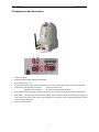
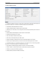
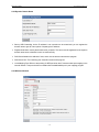
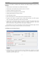
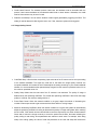
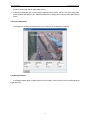
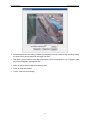
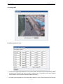
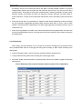
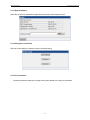
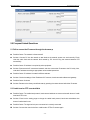
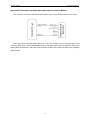
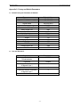
IP Camera
SGC 001D SGC 001DW
Operating Instructions
Version V1.0 Release
Announcement
This manual may not accurately describe on some technical details or contain some printing
error. If you could not solve problems occurred in the application process by the user manual, please
call at our technology department for relevant operational methods. This manual is subject to
nonscheduled change without further notice.
Packing List
Name
Quantity
IP camera
1
DC12V/1.0A Power Adapter
1
51KΩ Resistance
Line Terminal
2
1
Attached Compact Disk
1
Matters Needing Attention
1.
2.
3.
Installing Condition
I Far away from high-temperature resource and environment; avoid exposing under the sun
directly.
I Avoid improper place for ventilation for ensuring normal cooling of IP camera; water proof,
moisture proof, lightening protection. If need to install outdoors, also need to fix watertight
caisson and IP camera inside.
I Install this device on horizontal fixed place or cradle head. Avoid install on shaky place, and
don’t put other devices on it.
I When using wireless function, avoid or reduce obstacles on transmission path as possible.
Avoidance of Electric shock and Misfire
I Don’t touch power supply and IP camera by wet hands.
I Don’t spill liquor on IP camera to avoid short circuit and misfire in machine.
I Don’t put device on this IP camera.
I Nonprofessional people don’t open it to avoid damage and electric shock.
Transportation and Transit
I The packing of this machine is through aseismatic design and experiment to assure no
accidental damage of server in process of transportation. So it’s better to use original packing
material and carton while carry it.
I Avoid carrying server between superheating and super-cooling place for fear of dew inside
machine so as to affect the service life.
Content
1.0 Product Introduction ......................................................................................................................................4
1.1 Production Introduction ............................................................................................................................4
1.2 Technical Specifications ...........................................................................................................................5
2.0 Appearance and Description........................................................................................................................5
3.0 Equipment and Installation...........................................................................................................................6
3.1 Operating Conditions................................................................................................................................7
3.2 Equipment Installation ..............................................................................................................................7
4.0 IE Version Client Side ...................................................................................................................................7
4.1 Preparation Works.....................................................................................................................................7
4.2 Login and Image Browse ..........................................................................................................................7
4.3 Control Panel ............................................................................................................................................8
4.4 Configure IP camera ...............................................................................................................................10
4.4.1 Clock Adjustment......................................................................................................................10
4.4.2Video Format..............................................................................................................................10
4.4.3 Network Address and Port ...................................................................................................... 11
4.4.4 Dynamic Domain Name ..........................................................................................................12
4.4.5 Wireless Network .....................................................................................................................12
4.4.6 Display Control and Channel Protocol ..................................................................................13
4.4.7 Image Quality Control..............................................................................................................14
4.4.8 Colour Adjustment....................................................................................................................15
4.4.9 Moving Detection......................................................................................................................15
4.4.10 Image Mask.............................................................................................................................17
4.4.11 Moving Detection Plan...........................................................................................................17
4.4.12 Probe Alarm ............................................................................................................................18
4.4.13 System Updating....................................................................................................................19
4.4.14 Setting Save and Restore.....................................................................................................19
4.4.15 User Information.....................................................................................................................19
5.0 Frequent Asked Questions.........................................................................................................................20
5.1 Fail to access the IP camera through the browser? ...............................................................................20
5.2 Cradle head or PTZ uncontrollable.........................................................................................................20
5.3 Can’t play video normally after program updating.................................................................................21
5.4 Fail to browse images normally in Windows98......................................................................................21
5.5 How to use IP camera to realize video transmission service on public network (Internet).....................21
5.7 Why can’t the Normal Data pass through switch....................................................................................21
5.8 Why do errors occur when accessing the IP camera through the browser after updating.......................22
6.0 Appendix .......................................................................................................................................................23
Appendix A: Problem Description on Occupation (Mapping) of IP Camera Port........................................23
Appendix B: Description on Alarm Input and Output Connection Method..................................................24
Appendix C: Factory-set Default Parameters ...............................................................................................25
SmarterEE GmbH
www.SmarterGuard.com
1.0 Product Introduction
Thanks for using our product and we’ll provide you with the best service.
The IP camera is the equipment dedicated for real-time transmission of digital video and audio in Ethernet.
Adopting high-performance SOC (ARM+DSP) specially designed for multi-media processing. The IP
camera, which combines high-performance operating system and audio-video compression algorithm,
makes the image transmission more fluent and display more clear and smooth; in addition, including the
built-in WEB server, it can enhance the performance of traditional monitoring system, and provide the
network connectivity for issuing the monitoring images on a safe local area network or internet. The
management, configuration, monitoring and other functions of video camera can be operated easily
through the Internet Explore.
1.1 Production Introduction
Ø
Standard H.264 Video Compression Format
Ø
Standard G.722 Compression Format
Ø
Support D1, HALF-D1 and CIF Resolution
Ø
With the built-in Web Server, it fully supports IE monitoring, configuration and updating
Ø
The dynamic rate adjusting assures the real-time transmission of audio on Internet
Ø
User management supports the three-level user and password
Ø
Alarm input and output support motion detection, date, time, and event trigger.
Ø
Support local video record
Ø
Support image mask
Ø
Support image capturing
Ø
Support Auto Iris
Ø
Support Wireless 802.11b/g
-4-
SmarterEE GmbH
www.SmarterGuard.com
1.2 Technical Specifications
Video Compression
H.264
CPU
HI3510
Frame rate
PAL/25,NTSC/30
Motion detection
Yes
Watermark
Yes
White balance
Auto
CCD
1/3" 420TVL SONY CCD
Minimum Illumination
0.5Lux
AGC
+26dB Max
Audio Compression
G.722
Audio format
8kbit/s
Network Connector
10/100MBaseT,RJ-45
IE Browser
Support
DDNS
Support
PTZ Control
Support
Alarm IO
1/1
WiFi
Wireless 802.11b/g
Infrared Distance
20(m)
Protocol
HTTP,TCP/IP,UDP,DNS
Temperature
-10℃-55℃
Humidity
5%-85%RH
Power
DC12V/1A
-5-
SmarterEE GmbH
www.SmarterGuard.com
2.0 Appearance and Description
SGC001D(W)
1
3
8
2
4
7
5
6
1.
Interface of antenna.
2.
Data transmission indicator of Wireless LAN (W LAN).
3.
Power socket, DC12V, 1.0A.
4.
System status indicator, twinkle means system working fine ; Power indicator light, lightening means fine power system
5.
System switch: SW 1bit Not Off: normal start
SW 2bit Not Off: normal start
Switch On: emergent start
Switch On: system parameter initialization
6.
RJ45 network interface: Yellow light refers fine network connection; twinkle of green light refers status of network data.
7.
Reset button – For resetting the camera to factory settings, press a needle-like object into this hole while plugging the
power cable into the power socket and then hold the pressing for 15 seconds or longer, afterwards disconnect and then
connect the power cable again.
8.
External sensor connectors.
-6-
SmarterEE GmbH
www.SmarterGuard.com
3.0 Equipment and Installation
3.1 Operating Conditions
Operating System: Windows2000/XP/Windows2003/vista
Client PC: P4/128MRAM/40GHD/, and Scaling-Supported Graphic Card and DirectX8.0 Above
3.2 Equipment Installation
a.
Connect the IP camera into your network or into to the PC directly by the crossed twine.
b.
Switch on Power (DC 12V)
c.
Under the normal condition, the connection light (orange) of network interface will light on within 5
seconds, data indicator light (green) will twinkle, and the physical connection of the IP camera is
finished at this time.
4.0 IE Version Client Side
4.1 Preparation Works
1)
IP address of each IP camera is defaulted as 192.168.1.19 and subnet mask is defaulted as
255.255.255.0.
2)
Test whether the IP camera starts up normally. Under the Windows System, operate as <Start →run
→command> to open the command window to input
3)
<ping 192.168.1.19>
4)
When using the Internet Explore at the first time, you must lower the security setting casually so as to
install the ActiveX components once, and then select the Tool à Internet Options à Security à
Customize Levelà ActiveX Control and Plug-In>
5)
Setup the security level as low and click the Apply button. Input 192.168.1.19 into address bar of browser.
If pop up a dialogue box to ask if you want to install, please click yes to start the installation.
6)
Once ActiveX installation is finished, restore default value of security setting.
4.2 Login and Image Browse
1)
Login page will appear as follows after input default IP address of IP camera: 192.168.1.19 into the
address bar of browser.
-7-
SmarterEE GmbH
www.SmarterGuard.com
2)
Input the user name: 888888 (factory-set default, administrator user) or 1 (common user)
3)
Input the password: 888888 (factory-set default, administrator password) or 1 (common user)
4)
Click 【Enter】button to log in IP camera and enter the preview page of image, as following picture.
5)
You can click [start] and [stop] buttons on control panel at right side to stop or restart the connection.
During the connection process, the type font ‘connecting’ will appear at the top left corner of the display
area.
4.3 Control Panel
【Network Mode】: TCP and Multi-Cast can be selected according to your demand. Note: please select
again after the page is switched.
【Start-up】: After entering into preview interface, the image will automatically be connected.
-8-
SmarterEE GmbH
www.SmarterGuard.com
【Preview Start】: Click
to connect images of this channel at the same time.
【Preview End】: Click
to stop images of this channel. The connection state of current channel can
be known through the state of buttons.
【Wireless Network】: You can configure connecting into the WLAN (Optional according to different device
types).
【Image Capture】: Click this button to save the current screen image and store it under the temp directory of
C disk.
【Audio】: Click the audio button to open the audio connected to the current channel, and the state of button
will change into green. When switching to other channel, the audio will be also switched to this channel.
【Talkback】: Click the talkback button to start up the talkback and the state of button will change into green.
Click the button again to stop talkback.
【Video Recording】: Select the channel to be recorded and then click the button. Till the state of button
change into green, the system will start video recording. Click the button again to stop video recording. The
video recording is defaulted to be stored in the folder named as date in D disk. For example, the recording
file on 24th, March, 2005 is saved in ‘20050324’ folder. If the space of D disk is full, the system will
automatically switch to next disk to save the video files. If no enough space in disk, the earliest files will be
deleted and the newest files will be saved.
【Playback】: Click this button to display the playback interface. Please select the date and time by click of
arrow, the system will automatically inquire about the existing video recording. Click the file to play it
directly by the Media Player.
【Parameters】: Enter the setting page of IP camera parameter.
【Output Control】: Four output state control buttons can control small signal electrical relays on the IP
camera, and show the state of electrical relay through the colour state.
【Image Size】: The size of image display can be selected and the maximum size is the
full-screen display.
【Cradle head control】: Click four directional buttons to control the moving direction of
cradle head; click
and
to control the focus of camera lens. In addition, select
the speed stretch bar to confirm the moving speed of cradle head.
【Lens Control】: Click ‘lens control’ link to display mini control panel of lens, as follows.
and
are setting and invoking buttons of preset site.
The text box between two buttons is used to input number of
preset site. IRIS refers aperture of lens. FOCUS refers focus of
lens. Click
to shut down the control panel of lens.
-9-
SmarterEE GmbH
www.SmarterGuard.com
4.4 Configure IP camera
Click button【parameter】 in control panel at right side of video preview page, and enter the setting
page of IP camera parameter. The setting of IP camera parameter contains time setting, network setting,
channel and image setting, etc. See the picture at right side.
4.4.1 Clock Adjustment
The clock of network camera can be adjusted to lie over and display on the real-time image
synchronously with the connected computer.
4.4.2Video Format
You can select it as PAL or NTSC. Change of this setting comes into effect by reboot IP camera.
- 10 -
SmarterEE GmbH
www.SmarterGuard.com
4.4.3 Network Address and Port
Ø IP Address: IP address of IP camera. If apply at the local area network, please take notice that don’t set
the IP address collide with the IP address of computers located in the local area network.
Ø
Subnet Mask: Subnet Mask address of IP camera.
Ø
Gateway: Gateway address of network where IP camera locates.
Ø WEB server port: ‘web server port’ can change the browser access port provided by the web server of
the IP camera.
Ø
Multicast address: Multicast address of network where IP camera locates.
Ø
Multicast port: Multicast port of IP camera.
Ø
Alarm host address: IP address of alarm server.
Ø
Alarm host port: data transmission port of alarm server.
Ø
Remote host address: IP address of server host for remote data reception from IP camera.
Ø
Remote host port: data transmission port of server host for remote data reception from IP camera.
Ø Transmission starting port: “transmission starting port” can change the AV port used during network
transmission of IP camera (see Appendix A for details about port using).
Ø
MAC address: just displays the MAC address of IP camera. This cannot be modified.
Ø
PPPOE: “Disable” or “enable” PPPOE function to build network connection are optional.
Ø
PPPOE user: Username for PPPOE virtual dial-up.
Ø
PPPOE password: password for PPPOE virtual dial-up.
- 11 -
SmarterEE GmbH
www.SmarterGuard.com
4.4.4 Dynamic Domain Name
Ø
Start up URL forwarding: As the IP address is not convenient to be memorized; you can register the
domain name to get rid of annoyance of inputting the IP address.
Ø
Register Host Name: namely the domain name you prefer. This name must be registered on the dynamic
domain name server; otherwise it won’t be used normally.
Ø
DNS Server Address: the address of host, which runs the domain name service program.
Ø
DNS Server Port: The monitoring port of domain name service program.
Ø
Local Mapping Port: Refers to the pointing of WEB port when the IP camera makes port mapping in the
internal network. This port should be consistent with the defaulted 80 port in port mapping program.
4.4.5 Wireless Network
- 12 -
SmarterEE GmbH
www.SmarterGuard.com
IP address of IP camera in wireless LAN is different from default IP address, and can be set
separately.
Ø
CDMA parameter: choose whether start up CDMA wireless network.
Ø
Wireless status: choose whether start up WLAN connection of IP camera.
Ø
IP address: IP address of IP camera in WLAN.
Ø
Subnet mask: subnet mask address of IP camera in WLAN.
Ø
Gateway: gateway address of IP camera in WLAN.
Ø
DNS: DNS address of WLAN.
Ø
SSID: wireless network ID, is used to recognize the ID of wireless local network.
Ø
Encryption mode: selection of encryption mode of wireless data transmission. Use WEP encryption
mode. Two encryption modes: WEP-64 or WEP-128 can be selected.
Ø
Content of key: fill corresponding content of key according to encryption mode selected. When select
WEP-64 mode, need to input 5 characters in ASCII or 10 numbers in hexadecimal. When select
WEP-128, need to input 13 characters in ASCII or 26 numbers in hexadecimal.
After modification, click ‘confirm’ to confirm setting. Then enter ‘setting save and restore’ page, click ‘save
setting’ button to save all setting, and reboot IP camera so as to come into effect.
4.4.6 Display Control and Channel Protocol
Ø
Character Overlay: You can select the character content and display time to superpose on the image.
The position of display character and time on the image can be also adjusted and the position
coordinates on top left of image is (0, 0).
- 13 -
SmarterEE GmbH
www.SmarterGuard.com
Ø
Cradle Head Protocol: The selected protocol, baud rate, and address must be accordant with the
protocol, baud rate and address of the selected cradle head or dome camera. Otherwise, the cradle
head or dome camera may be out of control.
Ø
Detection and Backup: You can set the duration of alarm signal generated by triggering the GPIO. This
setting is used to detect the video signal is lost or not. If lost, the alarm system will be triggered.
4.4.7 Image Quality Control
Ø
Code Rate Setup: refers that the compressing input code rate of the IP camera can be set up according
to the network bandwidth. The higher the code rate is, the better the image quality. However, the
occupied bandwidth will increase as well. Please adjust the setting according to your actual bandwidth
situation. It’s recommended that the quantized setup ranges from the maximum quantized value of 31 to
the minimum quantized value of 4.
Ø
Quality Setup: Mean that the code rate of the IP camera is not restricted. The quality of image is
determined by the quantizing coefficient. The smaller the quantizing coefficient is the refiner the image
quality is. However, the minimum setting shall be 4.
Ø
Frame Rate Control: When the network condition is not good, adopt the method of decreasing the
number of frames per second to get more smooth and fluent effect of moving images.
Ø
Maximum Quantizing Coefficient: When the network condition is not good, the system will automatically
adjust the quantizing coefficient of coding to decrease the quantity of image coding data. When reaching
the limit value, if the network environment still fails to reach the requirement, the coder will decrease the
frame rate to control the image continuity to reach the optimal visual effect. No matter selecting the
quality coding or rate coding, above parameters are relevant to each other. For example, when doing
setup of the coding quality, the value of code rate parameter in the code rate setup will become the
- 14 -
SmarterEE GmbH
www.SmarterGuard.com
maximum coding rate used in quality setup coding.
Ø
Image Size: adjustable size of coding image. Optional choices are D1, Half-D1, DIF, three image sizes,
and compatible downwards in turn. Note that modification of image size comes into effect after reboot of
server.
4.4.8 Colour Adjustment
The brightness, contrast, saturation and hue of the channel can be adjusted as required.
4.4.9 Moving Detection
It can detect whether there is mobile object in current images. If alarm output is set, the mobile object will
trigger the alarm.
- 15 -
SmarterEE GmbH
www.SmarterGuard.com
Ø
Sensitivity Adjustment: the setting of adjusting the detecting sensitivity. Under the high-sensitivity setting,
the object moving at slow speed will also trigger the alarm.
Ø
Test Switch: Open this switch to test that the sensitivity you set is appropriate or not. If it triggers, a little
grey block will twinkle in the triggered area.
Ø
Select All: Set the whole image as the detecting area.
Ø
Clean All: Clean the set area.
Ø
Confirm: Save the current setting.
- 16 -
SmarterEE GmbH
www.SmarterGuard.com
4.4.10 Image Mask
4.4.11 Moving Detection Plan
Ø
The IP camera supports the selection for many kinds of alarm methods and implementation time, and the
arrangement of all kinds of plan tasks is set at the ‘detection plan’. The detection plan can be designed
as the project of various complex monitoring starting and closing.
Ø
No matter the moving detection or the external alarm detection, there is a task schedule list. According to
- 17 -
SmarterEE GmbH
www.SmarterGuard.com
the setting in this list, the IP camera will start or stop alarm. The task schedule consists of 7 groups of
settings totally, and each group includes the date, start time and end time. The first row on the left is
optional for date。During this row, each group contains Monday, Tuesday, Wednesday, Thursday, Friday,
Saturday, Sunday, from Monday to Friday, from Saturday to Sunday, Everyday, and Close, totally 11
kinds of selections. The two columns behind the data selection refer to the setting of start time and end
time.
Ø
During the moving alarm, the parameters for setting the alarm area and adjusting the alarm sensitivity
are very important. Inappropriate parameters easily cause the false alarm or miss in case of alarm
situation. The external alarm is dependent on the alarm signal triggered by the external inductor, such as
infrared siren, etc.
Ø
When the moving detection is started, the IP camera will detect the moving objects within the alarm area
during the scheduled date and time, and trigger the linking video recording or alarm output according to
the setting below.
4.4.12 Probe Alarm
When starting the probe detection, the IP camera will receive the message from the external sensor
during scheduled date and time, and trigger the linking video recording or alarm output according to the
setting below.
Ø
Arranged Schedule: totally 7 groups of time are arranged in different periods of time.
Ø
Linking Video Recording: Make video recording when alarm trigger exists.
Ø
Start Alarm Output: When alarm exists, the external alarm output will be started to trigger the externally
attached siren.
(For the detail way of alarm input and output connection, please refer to Appendix C)
- 18 -
SmarterEE GmbH
www.SmarterGuard.com
4.4.13 System Updating
Select the .itm file to be updated and update the program within the equipment by self.
4.4.14 Setting Save and Restore
Save the current settings or restore the factory-set default setting.
4.4.15 User Information
Support the password supervisor privilege and only administrator can modify the parameters.
- 19 -
SmarterEE GmbH
www.SmarterGuard.com
5.0 Frequent Asked Questions
5.1 Fail to access the IP camera through the browser?
n
Possible Cause: The network is disconnected?
n
Solution: Connect PC into the network to test whether the network access can work normally. Firstly
clear the cable fault and the network fault caused by PC virus till Ping the network between PCs
successfully.
n
Possible Cause: IP address is occupied by other equipment.
n
Solution: Disconnect the IP camera and network, and then connect the IP camera to the PC solely. Also,
reset the IP address according to appropriate recommended operations.
n
Possible Cause: IP address is located in different subnets.
n
Solution: Check the settings of the IP address of IP camera, the subnet mask address and gateway.
n
Possible Cause: Unknown
n
Solution: Restore to the factory-set default state by pressing the restore button behind the IP camera.
5.2 Cradle head or PTZ uncontrollable
n
Possible Cause: The cradle head protocol, baud rate and address are not accordant with those of cradle
head and PTZ in use.
n
Solution: Enter into the setting page to change the cradle head protocol, baud rate and address into
those of cradle head in use.
n
Possible Cause: The signal wire is poor connected or incorrectly connected.
n
Solution: Connect the control wire from cradle head or PTZ to IP camera again.
- 20 -
SmarterEE GmbH
www.SmarterGuard.com
5.3 Can’t play video normally after program updating
n
Solution: Close all the browser pages; search the NetClient.dll, NetViewX.cab, NetViewX.ocx file under
the C:\ directory, and delete them. Then connect the IP camera by the browser again, and the IP camera
will automatically appear on the new play plug-in.
5.4 Fail to browse images normally in Windows98
n
Solution: Install the DirecteX8.0 or higher version. Update the IE Explore to 5.5 above in version. Version
6.0 is recommended.
5.5 How to use IP camera to realize video transmission service on public network
(Internet)
If you want to make the IP camera transmit the data on Internet, you must know your network access
mode firstly. If the public network owns the static IP address, you should set the IP address, subnet mask and
gateway of IP camera as the static address provided by ISP directly so that you can browse normally. In
addition, the most widely-applied network access, respectively are ADSL and district broad band, both
require the authentication process. The authentication can be finished through some intelligent equipment,
such as PC or small-sized router. If located in LAN, an IP address of the public network will be set, so that the
external network can not see the inside of LAN. In this case, some settings shall be done on the connected IP
camera.
n
Solution:
Ø
If used in LAN of office and building, but still want to visit this IP camera from other cities, you can make
the forwarding by taking advantage of the machine accessing into the Internet. Concretely you can use
the port mapping to finish the forwarding of information packet. For some popular port mapping software
now, only simply setting is required. Select all the IP among the visited IP addresses, and then fill the
internal address of the IP camera in LAN as the end IP address.
Ø
In case of no PC, selecting the router as the forwarding equipment is also not a bad solution. At present,
most routers own the function of port mapping, or also called DMZ. Appoint the DMZ address as the
address of IP camera.
Ø
Set a VPN server as the server of virtual privacy network, and then dial up at the remote client side. After
connecting well, it can visit the internal host.
5.7 Why can’t the Normal Data pass through switch
n
Possible Cause:
1)
In case of the layer 2 switch, the address is written wrong?
2)
In case of layer 3 switch, the bindings of port and physical address are done or not?
3)
When configuring the firewall rule, whether take IP camera into account.
n
Solution:
- 21 -
SmarterEE GmbH
www.SmarterGuard.com
Ø
Before searching the network fault, please be sure to use the ping command in the command mode
to connect the address on the other side. To check the message returned from ping is a very
important step. If no message is returned, it indicates that some faults must exist in the network.
Ø
If the IP address and Mac address are bound, adding a new binding of IP address and Mac address
of the IP camera within the exchanger is required inside switch.
Ø
If the IP camera never be considered when configuring the firewall rule of switch, it’s necessary to
allow the communication on ports 3000, 3001, 3002, 3003 and 80 for the IP camera. Otherwise, any
data packet will be filtered and can’t reach target.
5.8 Why do errors occur when accessing the IP camera through the browser after
updating
Delete the buffer of the browser. The detailed steps are as follows: open the tool menu of browser to
open the Internet option, and then click the “Delete File” button in the second item (temporary file of Internet)
and check the “Delete All Offline Contents” option. And then confirm it, and finally login the IP camera again.
- 22 -
SmarterEE GmbH
www.SmarterGuard.com
6.0 Appendix
Appendix A: Problem Description on Occupation (Mapping) of IP Camera Port
This IP camera occupies the following ports when doing the video transmission service on the Internet:
TCP:
80-----WEB port
3000-----Data transmission starting port
3001-----Data control port
IP camera must follow the port mapping operation of these three ports above so as to be accessed from
public network.
If one IP address exits several IP cameras, corresponding ports of IP cameras must be modified as
required, such as Web and data transmission starting port, plus 1 on the basic address in turn.
UDP transmission port is 3002.
Multicast port is: port number + channel number *2.
- 23 -
SmarterEE GmbH
www.SmarterGuard.com
Appendix B: Description on Alarm Input and Output Connection Method
The common connection method between alarm input of the IP camera and alarm siren:
Alarm siren has two working status, always on or off. The connection way is as picture above. After
connecting alarm siren, choose corresponding probe mode, start probe alarm, and set alarm time due to
working status of alarm siren. That’s all to finish connection of alarm siren. At this time, alarm siren is awaiting
orders of alarm.
- 24 -
SmarterEE GmbH
www.SmarterGuard.com
Appendix C: Factory-set Default Parameters
l
Default Factory-set Parameters of Network:
Parameters
IP Address
IP Address of Wireless LAN
Subnet Mask
Gateway
Transmission Starting Port
Data Control Port
Web Port
Multi-Cast Address
Multi-Cast Port
DDNS
Moving Detection
Probe Alarm
PPPOE
Remote Host Port
DNS Port
l
Default Value
192.168.1.19
192.168.0.19
255.255.255.0
192.168.1.1
3000
3001
80
235.1.1.1
6500
Off
Off
Off
Off
3004
8080
User and Password:
Parameters
Factory-set Default Username
of Administrator
Password
Factory-set Default Username
of Normal User 1
Password
Factory-set Default Username
of Normal User 2
Password
Default Value
888888
888888
1
1
2
2
- 25 -
SmarterEE GmbH
www.SmarterGuard.com
Thanks for using this IP camera. Due to the differences among each models or
appearance, function differing from those described in this manual because of system
software updating, please contact the manufacturer at any time. We feel sorry that we
could not inform you these changes timely.
- 26 -


![- [ [ [ ANSEL ] ] ]](http://vs1.manualzilla.com/store/data/005876018_1-a636cab6934c7a831e92a71c6eb2f063-150x150.png)