1
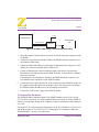
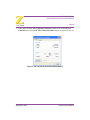
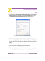
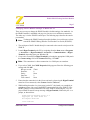
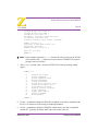
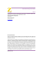
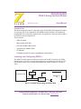
ZDI232ZPAK2ZPK
ZPAK II Debug Interface Module
User Manual
UM016301-1003
Introduction
This document describes how to setup and use the ZiLOG ZPAK II Debug Interface Module with your ZiLOG development kit. The ZPAK II module enables a development PC
running ZDS II to communicate with a ZiLOG development kit. It also provides an Ethernet interface to the development PC.
The kit includes:
•
ZPAK II module
•
DB9-to-ID10 serial cable
•
Keyed 40-conductor ribbon cable
•
Target Interface Module (TIM)
•
User Manual
•
CD-ROM with ZDS II software and additional documentation
Installing and Configuring ZPAK II
The ZPAK II module features an Ethernet interface and an RS-232 console port. Slight
modifications to your PC’s network configuration may be required for first-time use. Follow the steps in this section to install and configure the ZPAK II module. See Figures 1
and 2.
Development PC
Ethernet
Hub
RJ-45
5 VDC
¤
eZ80
Development
Platform
Development
RJ-45
KiteZ80
Development
Module
¤
ZPAK II
RS-232
9 VDC
TIM ZDI
Figure 1. Hardware Setup using an Ethernet Hub
ZiLOG Worldwide Headquarters • 532 Race Street • San Jose, CA 95126
Telephone: 408.558.8500 • Fax: 408.558.8300 • www.zilog.com
ZDI232ZPAK2ZPK
ZiLOG ZPAK II Debug Interface Module
Page 2
5 VDC
Development PC
¤
eZ80
Development
Platform
Development
Crossover CAT5
Kit
eZ80
eZ80
Development
Module
Module
ZPAK II
RS-232
9 VDC
¤
TIM ZDI
Figure 2. Hardware Setup using a Crossover Ethernet Cable
1. Set up the target development kit as described in its quick start guide (supplied on the
CD-ROM).
2. Connect the Target Interface Module (TIM) to the ZPAK II module using the keyed
40-conductor ribbon cable.
3. Connect the TIM to the ZDI port on the target development board. Align pin 1 of the
TIM to pin 1 of the development board’s ZDI socket.
5. If using an Ethernet hub, connect an Ethernet patch cable from a free port on the
Ethernet hub to the Ethernet port on the ZPAK II module. Connect the PC’s Ethernet
port to the same hub.
If connecting the development PC directly to the ZPAK II module, connect a crossover Ethernet cable from the PC to the ZPAK II module.
6. Connect the serial COM port on the PC to the console port on the ZPAK II module via
the supplied serial cable and the 10-pin adapter cable. (You may need to reconfigure
the ZPAK II module IP address for your networking environment.)
7. Connect the 5 VDC power supply to the ZPAK II module.
Configure the Hardware
The default IP address and subnet mask of the ZPAK II module are 192.168.1.50 and
255.255.255.0, respectively. To enable communication between the PC and the ZPAK II
module, you must either change the PC’s Ethernet settings to match those of the module or
vice versa.
If using the PC in a non-networked configuration, set the PC’s IP address to 192.168.1.21
and its subnet mask to 255.255.255.0. See “"Changing the PC’s Settings to Match the
ZPAK II Module"” on page 3 for instructions.
UM016301-1003
Configure the Hardware
ZDI232ZPAK2ZPK
ZiLOG ZPAK II Debug Interface Module
Page 3
If working in a networked environment, set the ZPAK II module IP address and subnet
mask to match the existing network setup. See “"Changing ZPAK II Module Settings to
Match the PC"” for instructions.
Changing the PC’s Settings to Match the ZPAK II Module
The following instructions are for the MS Windows XP platform. If your Windows operating system is different, please refer to your MS Windows OS online help for details.
1. Open the Windows Control Panel and double-click the Network and Internet
Connections icon. The Network Connections dialog box appears (Figure 3).
Figure 3. The Network Dialog
UM016301-1003
Configure the Hardware
ZDI232ZPAK2ZPK
ZiLOG ZPAK II Debug Interface Module
Page 4
2. In the panel labeled LAN or High-Speed Internet, double-click the Local Area
Connection icon. The Local Area Connection Status dialog box appears (Figure 4).
Figure 4. The Local Area Connection Status Dialog
UM016301-1003
Configure the Hardware
ZDI232ZPAK2ZPK
ZiLOG ZPAK II Debug Interface Module
Page 5
3. In the Local Area Connection Status dialog box, click the Properties button. The
Local Area Connection Properties dialog box appears (Figure 5).
Figure 5. The Local Area Connection Properties Dialog
UM016301-1003
Configure the Hardware
ZDI232ZPAK2ZPK
ZiLOG ZPAK II Debug Interface Module
Page 6
4. In the panel labeled This connection uses the following items:, select the Internet
Protocol (TCP/IP) item to highlight it, and click the Properties button (Figure 5).
The Internet Protocol (TCP/IP) Properties dialog box appears (Figure 6).
Figure 6. The Internet Protocol Properties Dialog
5. Enter values for the IP address and subnet mask to match those shown in Figure 6.
Leave any remaining fields blank. In this example, an IP address of 192.168.1.21 and
a subnet mask of 255.255.255.0 are being assigned to the PC. These values place the
PC on the same network as the ZPAK II unit, and do not conflict with the IP address of
ZPAK II.
6. Click OK and restart the PC.
7. The PC is now ready to communicate with the ZPAK II module.
8. The default IP address of the ZPAK II module is 192.168.1.50. If this address conflicts with another address on the LAN, or if another address is more compatible, proceed to "Changing ZPAK II Module Settings to Match the PC" on page 7.
UM016301-1003
Configure the Hardware
ZDI232ZPAK2ZPK
ZiLOG ZPAK II Debug Interface Module
Page 7
Changing ZPAK II Module Settings to Match the PC
There are two ways to change the ZPAK II module’s default settings. One method is via
the ZPAK II module’s embedded web page via a browser over an Ethernet connection.
The other way is via the ZPAK II console port. The following steps describe the console
port method.
Note: To change the ZPAK II settings from their defaults via a web browser, please
consult the ZPAK II Debug Interface Tool Product User Guide (PUG0015).
1. The serial port of the PC should already be connected to the console serial port of the
ZPAK II.
2. Launch HyperTerminal on the PC by navigating from the Start menu to Programs
→ Accessories → HyperTerminal or Accessories → Communications → HyperTerminal, depending upon your Windows OS.
3. Create a new connection in HyperTerminal by selecting the appropriate COM port in
the Connect using: field of the Connect To dialog. Click OK.
Note: This connection is a direct connection via a COM port, not a modem.
4. If you select COM1, the COM1 Properties dialog appears. Enter the following port
settings and click OK.
Bits per second: 57600
Data bits:
8
Parity:
None
Stop bits:
2
Flow control:
None
5. Ensure that the connection is in the Connected state by observing the HyperTerminal
status bar. If not connected, select Connect from the Call menu.
6. While holding down the z key (lowercase) on the PC’s keyboard, use a toothpick or
straightened paper clip to press the RESET button on the side of the ZPAK II. (The
RESET button is recessed within the side of the ZPAK II.) Releasing the z key displays a ZPAK II console boot-up message in HyperTerminal, followed by the ZPAK
prompt, as shown below.
ZiLOG TCP/IP Software Suite v1.1
Copyright (C) 2003 ZiLOG Inc.
All Rights Reserved
clock enabled
UM016301-1003
Configure the Hardware
ZDI232ZPAK2ZPK
ZiLOG ZPAK II Debug Interface Module
Page 8
created buffer Pool 1524 32
created buffer Pool 4096 8
IP Address: 192.168.1.50
IP Subnet: 192.168.1.0/255.255.255.0
IP Gateway: 192.168.1.254
netstart exiting, stack extent 379/2048
ZPAKII version y.y
Copyright © 2001-2002 ZiLOG, Inc.
All Rights Reserved.
ZPAKII Console version 1.5
Type 'H' for help
ZPAKII:>
Note: In the example output above, x.x.x denotes the current version of the TCP/IP
stack software, and y.y denotes the current version of ZPAK II. The console
prompt is not case-sensitive.
7. At the ZPAKII prompt, enter H and press ENTER. The following message should
appear:
ZPAKII:> H
H
I
S
G
P
V
B
F
C
A
D
W
R
display this Help
change Ipaddress
change ipSubnet mask
change ipGateway
change Portnumber
change dtli Variable count
change dtli Buffer size
load deFault settings
display Current settings
toggle pAssword
toggle Dhcp option
change passWord
Reset zpakii
ZPAKII:>
8. Use the I command to change the ZPAK II’s IP address to one that is compatible with
the PC. Use caution to avoid creating a conflicting IP address.
9. Use the S command to change the ZPAK II’s subnet mask to one that is compatible
with the PC. Typically, the subnet mask is the same as that of the PC.
UM016301-1003
Configure the Hardware
ZDI232ZPAK2ZPK
ZiLOG ZPAK II Debug Interface Module
Page 9
Note:
All changes are saved to Flash memory inside the ZPAK II.
10. Cycle the power on the ZPAK II for the new settings to take effect.
The hardware is now configured and ready for application development with the
eZ80Acclaim!™ module contained in this kit.
Compatibility with Microsoft Operating Systems
The ZPAK II Debug Interface Module is compatible with the following Microsoft operating systems when connected directly to the serial port of the PC:
•
WIN98SE
•
WIN NT
•
WIN2000
•
WIN XP
UM016301-1003
Compatibility with Microsoft Operating Sys-
ZDI232ZPAK2ZPK
ZiLOG ZPAK II Debug Interface Module
Page 10
This publication is subject to replacement by a later edition. To determine whether a later
edition exists, or to request copies of publications, contact:
ZiLOG Worldwide Headquarters
532 Race Street
San Jose, CA 95126-3432
Telephone: 408.558.8500
Fax: 408.558.8300
www.ZiLOG.com
Document Disclaimer
ZiLOG is a registered trademark of ZiLOG Inc. in the United States and in other countries. All
other products and/or service names mentioned herein may be trademarks of the companies with
which they are associated.
©2003 by ZiLOG, Inc. All rights reserved. Information in this publication concerning the devices,
applications, or technology described is intended to suggest possible uses and may be superseded.
ZiLOG, INC. DOES NOT ASSUME LIABILITY FOR OR PROVIDE A REPRESENTATION OF
ACCURACY OF THE INFORMATION, DEVICES, OR TECHNOLOGY DESCRIBED IN THIS
DOCUMENT. ZiLOG ALSO DOES NOT ASSUME LIABILITY FOR INTELLECTUAL PROPERTY INFRINGEMENT RELATED IN ANY MANNER TO USE OF INFORMATION,
DEVICES, OR TECHNOLOGY DESCRIBED HEREIN OR OTHERWISE. Devices sold by
ZiLOG, Inc. are covered by warranty and limitation of liability provisions appearing in the ZiLOG,
Inc. Terms and Conditions of Sale. ZiLOG, Inc. makes no warranty of merchantability or fitness for
any purpose Except with the express written approval of ZiLOG, use of information, devices, or
technology as critical components of life support systems is not authorized. No licenses are conveyed, implicitly or otherwise, by this document under any intellectual property rights.
UM016301-1003