1
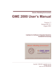
GME User’s Manual Rev 1.3 TEST INSTRUMENT SAFETY GUIDELINES WARNING An electrical shock of over 10 milliamps of current to pass through the heart will stop most human heartbeats. Voltage as low as 35 volts dc or ac rms should be considered dangerous and hazardous since it can produce a lethal current under certain conditions. Be sure to observe following safety precautions: 1. Do not expose high voltage needlessly in the equipment under test. Remove housings and covers only when necessary. Turn off equipment while making test connections in high-voltage circuits. Discharge high-voltage capacitors after removing power. 2. If possible, familiarize yourself with the equipment being tested and the location of its high voltage points. However, remember that high voltage may appear at unexpected points in defective equipment. 3. Use an insulated floor material or a large, insulated floor mat to stand on, and an insulated work surface on which to place equipment; make certain such surfaces are not damp or wet. 4. When using a probe, touch only the insulated portion. Never touch the exposed tip portion. 5. When testing ac powered equipment, remember that ac line voltage is usually present on some power input circuits such as the on-off switch, fuses, power transformer, etc. any time the equipment is connected to an ac outlet, even if the equipment is turned off. Limited One-Year Warranty GME Technology warrants to the original purchaser that this product and the component parts thereof, will be free from defects in workmanship and materials for a period of one years from the data of purchase. GME Technology will, without charge, repair or replace, at its’ option, defective product or component parts. Returned product must be accompanied by proof of the purchase date in the form a sales receipt. Term and Conditions The warranty period is based upon the invoice date of the original purchase by the end-user. Warranty only applies to defects in materials and/or workmanship, which occur during normal use. Warranty does not apply to those products that are damaged due to misuse, abuse, negligence or modification. Warranty does not extend to any damage that occurs in shipment or due to natural phenomenon (i.e. lightning or line surges). Warranty will be voided if the original serial number on the product is removed by accident or intentionally This warranty gives you specific rights and you may have other rights, which vary from state-to-state. Service & Repair The following are procedure for returning a GME product for servicing and repair. Turn around time for repair is normally within five (5) working days excluding shipping time. RMA Procedure Before sending your GME product in for service, be sure to contact GME Technology first to obtain a RMA number. If your product is still under warranty, please send in the product along with a copy of the receipt showing the date when the product was purchased. If the warranty has already expired, please ask for the repair cost when you contact GME Technology for the RMA number and include a check or money order for the repair cost when you send in the product. Please make check payable to: GME Technology You may send your GME product to our service & repair department at: GME Technology ATTN: Service & Repair Department 380 S. East End Ave., #H Pomona, CA 91766 Be sure to include a note showing your RMA number, your name, telephone number, return address, and a description of the problem with the product. For the most recent support information, please visit GME Technology website at www.gmetechnology.com/support Table of Contents Page Introduction …………………………………………………………………………. 1 Item Checklist ……………….…………………………………………………….... 1 Features ……………………………………………………………………………... 1 Understanding the Front Panel …………………………………………………….... 2-3 Operation and Measurement ….…………………………………………………….. 4-5 Specifications ………………….……………………………………………………... 6 GME Product Information …………………………………………………………… 7 Notes ……….………………….…………………………………………………….. 8-9 Introduction Thank you for purchasing the model 236 In-circuit ESR & DCR capacitor tester. This tester is designed to measure ESR (Equivalent Series Resistance) on capacitors range from 0.47µF to 2200µF, in or out of circuit. The ability to troubleshoot in-circuit saves valuable time, making the 236 a must for anyone that tests or troubleshoots PCB (printed circuit boards). The 236 is microprocessor controlled and automatically discharge capacitor under test. It features a 100 kHz output test frequency. Using a low 15 mV peak-to-peak output test voltage, the 236 will not turn on any solid state devices during testing for accurate test result. It also checks for low DCR (DC resistance). Item Checklist Model 236 In-circuit ESR & DCR capacitor tester One protective rubber holster One User’s Manual Features In-Circuit ESR & DCR testing Test capacitors range from 0.47µF to 2200 µF One-handed tweezers test probe Microprocessor controlled Automatic discharges capacitor under test 25 segment LED indicators AC adaptor power source or standard 9V battery operation Low battery indicator Ideal for on-the-bench and in-the-field testing Easy to use, lightweight, and portable Understanding the Front Panel 2 4 3 1 5 6 7 8 1. Power ON/OFF switch This Power ON/OFF switch is on the left side of the unit. Slide the switch upward to turn the unit on and downward to turn the unit off. 2. Power ON/OFF LED Power is ON when the LED lights up and power is OFF when the LED is off. 3. Battery Low LED When the 236 is operating on a standard 9V battery and the voltage on the battery has drop down to around 5V, this green LED will turn on indicating the voltage on the battery is low. 4. DCR LOW indicator LED When testing under the “DCR & ESR” mode, this LED turns on when DCR low www.gmetechnology.com 1 5. 9V AC adaptor input The user may connect a 9V 100mA 5.5mm x 2.1mm center positive AC adaptor (not included) to power the 236. 6. Test Mode Switch Use this selector to choose between the two available test modes: “DCR & ESR” mode or “ESR” mode. 7. ESR / DCR resistance LEDs 25 Segment LEDs used to indicate DCR or ESR resistance value of the capacitor under test 8. Three-Colored chart This three-colored chart shows the typical capacitor ESR reading. Use the chart to determine whether the capacitor under test is Good, Fair, or Bad. www.gmetechnology.com 2 Operation and Measurement Use the 236 to measure electrolytic capacitors in or out the circuit. Follow these instructions to determine the ESR value of the capacitor under test. Use the Three-Colored chart to determine whether the capacitor under test is Good, Fair, or Bad according to the ESR value shown. Select the “ESR & DCR” or “ESR” test mode. Slide the power switch to turn on the 236. The unit will automatically calibrate the internal circuitry. It will beep once to signal it is ready when the calibration is done. (NOTE: DO NOT short the tweezers test probe or connect the test probe to a capacitor before the unit beeps to signal it is ready, otherwise the unit will continue to sound an alarm until the test probe is open or the capacitor is removed) “ESR” Test Mode: 1. Hold the tweezers test probe across the leads of the capacitor wish to test. 2. The 236 will discharge the capacitor under test. Then it will measure the ESR of the capacitor and indicates the value with the 25 segment LED on the front panel. It will sound one or more times depending on the ESR of the capacitor (refer to Table I below). Table I: Beeps reference table for "ESR" mode: ESR Ohms 0 ~ 0.5 Ω Number of Beeps one (1) 0.5 ~ 1.0 Ω two (2) 1.0 ~ 3.0 Ω three (3) 3.0 ~ 8.0 Ω four (4) 8.0 ~ 30 Ω five (5) 3. Use the Three-Color table on the front panel to determine the condition of the capacitor. This table shows the typical capacitor ESR reading. Each small rectangular space has one of three colors: GREEN = good YELLOW = fair RED = bad The bottom of the table shows capacitor values from 0.47µF to 2200µF. The column of color spaces above each capacitor value shows the typical ESR reading for such capacitor. The ESR value of the capacitor under test is shown by one of the 25 segment LEDs. Compare this ESR value with the Three-Color table’s typical ESR reading for your capacitor to determine the condition of the capacitor under test. If the capacitor’s ESR range falls in the green area, then the capacitor is good. If the capacitor’s ESR range falls in the yellow area, then the capacitor’s condition is consider fair and is up to the test personnel to decide whether to replace it. If the capacitor’s ESR range falls in the red area, then the capacitor is consider bad and needs to be replaced. On “ESR” mode, the 236 will indicate a shorted capacitor is good because it does not perform DCR measurement under the “ESR” mode. Only in the “DCR & ESR” mode will the 236 detect shorted capacitor. www.gmetechnology.com 3 “DCR & ESR” Test Mode: 1. Hold the tweezers test probe across the leads of the capacitor wish to test. 2. First, the 236 will discharge the capacitor under test. Then it will measure the DCR (DC resistance). If the DCR is less than 30 ohm, the 236 will sound an alarm and turn on the “DCR LOW” LED. The DC resistance is shown by flashing the segment LEDs and sounding one or more times depending on the DCR value of the capacitor detected. (refer to Table II below) Table II. DCR Beeps and segment LED reference table for "DCR & ESR" mode: DCR Ohms 0 ~ 0.5 Ω 0.5 ~ 1.2 Ω 1.2 ~ 2.5 Ω 2.5 ~ 4.5 Ω 4.5 ~ 10 Ω 10 ~ 20 Ω 20 ~ 30 Ω Segment LED that will flash 0.5 Ω 1.2 Ω 2.5 Ω 4.5 Ω 10 Ω 20 Ω 30 Ω Number of Beeps one (1) one (1) two (2) two (4) three (3) three (3) three (3) 3. If the DCR value measured by the 236 is greater than 30 ohms, then the 236 will measure the ESR value and display it with the 25 segmented LED. Refer to the instruction under “ESR” Test mode to determine the condition of the capacitor. NOTE: Even though the 236 will automatically discharge capacitors before performing the testing routines, large capacitor with enough voltage stored may damage the test probe. Therefore, it is recommended that a large capacitor be discharged first before using the 236. The 236 is essentially an AC ohm meter under the “ESR” mode. It can be used to measure low value non-inductive resistors. It can also be used to measure small inductors and compare the ESR value shown by the 236 to the values of known good inductors. www.gmetechnology.com 4 Specifications Open circuit probe voltage Output Test Frequency 15 mVp-p 100 kHz sine wave ESR Measurement Range DCR Measurement Range 0.1 ~ 30 Ω display with 25 segment LEDs 0.5 ~ 30 Ω display with flashing LEDs Power Power Requirement one standard 9V battery OR 9V AC adaptor (150mA, 5.5mmx2.1mm center positive) 10 mA typical Dimension Weight 5.7"(H) x 3.8"(W) x 1.5"(D) 0.8 lb www.gmetechnology.com 5 WWW.GMETechnology.COM For product updates and information CHECK OUT THESE OTHER TEST EQUIPMENT AVAILABLE FROM GME GME offers many different types of electronic test equipment to suit your needs. Here are some of the test equipment products we offer. Model Description HG139 HDTV Pattern Generator SG-10 10 MHz DDS Signal Generator 236 In-Circuit ESR & DCR Capacitor Tester PG-16A NTSC & Monitor Tester (Handheld Model) PG-68 NTSC & Monitor Tester (Benchtop Model) PG-38 NTSC Pattern Generator MT-160 Computer Monitor Tester LC200 Digital LC Meter C350 Capacitance Meter Other products such as digital / analog panel meters, step motor drivers are also available. Please visit our website at www.gmetechnology.com for complete detail. www.gmetechnology.com 6 Notes www.gmetechnology.com 7 Notes www.gmetechnology.com 8