1
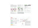
GYRO/ACCELERATION SENSOR EXTENSION BOARD
“VS-IX001” FOR VS-RC003
INSTRUCTION MANUAL
Advanced Telecommunications Research Institute International
Vstone Co., Ltd.
The Manual describes the methods for connecting a gyro/acceleration sensor
extension board “VS-IX001” to a small CPU board “VS-RC003” for robots to make
various settings with RobovieMaker for VS-RC003.
The VS-IX001 is capable of obtaining the information of a 3-axis acceleration sensor
and a 2-axis gyro sensor. The obtained information is written into the variables of the
CPU board and can be used to detect a tumble of a robot via the acceleration sensor and
automatically reproduce a motion or feed back the information of the gyro sensor to a
servo motor.
The Manual refers to some terms and words as follows:
- RovobieMaker for VS-RC003 ----- the Software
- VS-RC003 --- CPU board
- VS-IX001 --- Gyro/acceleration sensor extension board
*The Manual assumes that the firmware version of the CPU board is 1.00 (2) or later
and the version of the Software is Release 3 or later. In the environment not satisfying
this assumption, some functions are limited. If you do not have those latest versions,
download them from our official support page.
To check the version of the Software, select “Help” in the Software’s menu, followed by
“Version Information” to open a dialog window, and then, check with a field “Comment”.
To check the version of the CPU board, select “Project Setting” in the Software’s menu,
followed by “CPU-Board Setting” to open a dialog window, and then, check with a field
“Firmware Version.”
Official support page URL:
1. BASIC SETTING OF GYRO/ACCELERATION SENSOR EXTENSION
BOARD
1-1 Basic Setting Procedure
To use the gyro/acceleration sensor extension board, it is necessary to initially set
device bus addresses, variables used for writing, and so on. First, set a DIP switch on
the gyro/acceleration sensor extension board so that an I2C bus address will be 0x90.
(Set the SW1-3 and SW1-4 to OFF)
The DIP switch segments SW1-1 and SW1-2 are to set the sensitivity of the
acceleration sensor. For details, see “VSIX001 Hardware Manual.pdf.”
Then, connect the CPU board and the gyro/acceleration sensor extension board (see
an accompanying material to prepare a connection cable by yourself). Once they are
connected, start the Software, click on the
button on the tool bar to start
communication with the CPU board. After that, click on “Project Setting” in the menu,
followed by “CPU-Board Setting.”
The following dialog window opens. Click a tab index “Extension Device” to change
the dialog window’s contents, and click on the “Add” button appearing in the dialog
window.
Click on ”Extension Device”
Displays the settings of the
extension devices currently
registered with the CPU board.
Click on“Add.”
Clicking on the “Add” button opens the following dialog window. Select
“VS-IX001(gyro/acceleration sensor)” at “Device Type” and then, click on “Device Detail
Setting.”
Click on “Device Detail
Setting.”
Set “VS-IX001(gyro/acceleration
sensor)” at “Device Type.”
Clicking on “Device Detail Setting” opens the following dialog window where you can
set the details of the analog input extension board. Set the dialog window’s contents as
follows; their details will be described later.
*When connecting two or more analog input extension boards, be sure to assign
different numerical values to them because if they are set to the same values, the
variables and bus addresses will duplicate.
For “Parameter Storage Value,” set “0” for unused axes.
Once setting is completed, click on “Apply” in the dialog window. The following dialog
window opens, applying the settings to the CPU board. Click on “OK” to close the dialog
window.
Once the settings are applied to the CPU board, the current variable values set at
“Parameter
Storage
Value”
appear
at
“Now
Sensor
Parameter”
in
“VS-IX001(ADC/Gyro/Acceleration Sensor)Setting Dialog” in real time. (See the screen
image below)
The offset and gain values for each axis shown in the screen image are appropriate
ones. Set a higher gain value when greatly changing the input information, and set a
lower one when reducing a change, thus adjusting an input port. (See “1-2 Details of
Basic Setting” described later for a method to add an offset or a gain to the raw input
information)
After confirming that the input port information has been correctly obtained, click on
“OK” in the dialog window “VS-IX001(ADC/Gyro/Acceleration Sensor)Setting Dialog” or
“Addition/Change of Extension Device” to close the relevant dialog window, and then,
click on “Close” in the “CPU Setting” dialog window to close all the dialog windows of
the Software.
Then, write the settings reflected on the RAM of the CPU board into the ROM of the
CPU board. Click on “Project Setting” in the menu, followed by “Mode Switch/Sound
Map Srtting and Writing to CPU” and the
button on the tool bar to open the
following dialog window. Once it is opened, click on “Overwrite only Mode switch
setting,” followed by ”Execute Write.”
Click on “Overwrite only Mode switch
setting.”
Click on “Execute Write.”
1-2 Details of Basic Setting
The following describes the setting items of the gyro/acceleration sensor extension
board in detail. (To automatically reproduce a motion based on analog input, proceed to
“2. TUMBLE DETECTION AND AUTOMATIC REPRODUCTION OF GETTING UP
MOTION BY ACCELERATION SENSOR.” To feed back to the gyro sensor’s servo motor,
proceed to “3. FEEDBACK OF GYRO SENSOR VALUE TO SERVO MOTOR.”)
● Status Value --- Set a variable number to which the status of the extension device is
output. The status variable of the gyro/acceleration sensor extension board is defined to
be “128.”
● I2C Bus Address --- This setting is to distinguish various extension devices connected
to the CPU board. The I2C bus address of the gyro/acceleration sensor extension board
is defined to be “0x90.” Change also the setting of the DIP switch on the board.
● Parameter Storage Value --- Set a variable to which each axis information of the
sensor is output. Each axis has the variables “129, 130 and 131” defined to the X-, Yand Z-axis of the acceleration sensor, and those “132 and 133” defined to the X- and
Y-axis of the gyro sensor, respectively. Set 0 for unused axes.
● Offset --- Set an offset value for the sensor’s raw data obtained from each axis. Set the
value within a range of -32,768 to 32,767. For specific actions of the offset value to the
obtained raw data, see a calculation formula described later.
● Gain --- Set a gain for the sensor’s raw data obtained from each axis. A higher
numerical value results in more sensitive input. Set the value within a range of -32,768
to 32,767. For specific actions of the gain value to the obtained raw data, see a
calculation formula described later.
● Now Sensor Parameter --- Numerically displays the current sensor information. No
numerical values are displayed unless the settings of Parameter Storage Value are
applied once. They are not displayed if “0” is set at Parameter Storage Value.
For the final output value to Parameter Storage Value at each axis, a gain and an
offset are added to them by the following calculation formula.
[Output value to the variable] = [Gain]* ([Sensor ’s raw info.]・[Offset])/256
2. TUMBLE DETECTION AND AUTOMATIC REPRODUCTION OF
GETTING UP MOTION BY ACCELERATION SENSOR
The gyro/acceleration sensor extension board is capable of detecting a tumble of the
robot by means of the acceleration sensor’s value and making the robot automatically
reproduce a getting up motion. The following describes this setting method.
To make the robot automatically reproduce a motion according to the acceleration
sensor’s value, set “Operation Map” which operates the robot with a controller. If an
arbitrary variable satisfies a certain condition depending on the “Analog Input Setting”
items included in Operation Map, automatic reproduction of motion can be set.
Setting of Operation Map is not described in detail here. If you have any questions,
see “RobovieMaker for VS-RC003 Instruction Manual.pdf.
First, open the Operation Map Setting dialog window. Click on the
button on the
tool bar of the Software to open a dialog window for writing the mode switch settings to
the CPU. Then, click on any desired number in the Mode Switch Setting list on the left,
followed by “Create New Operation Map.”
Click on any desired number in the mode
switch list.
Click on “Create New Operation Map”.
Clicking on “Create New Operation Map” opens the Operation Map Setting dialog
window below.
Set at “Analog 1-4” the motion
Set the motion reproducing conditions for
files to be reproduced by analog
the acceleration sensor’s value at “Analog
input.
Input Setting.”
For the “Analog Input Setting” items located at the right middle in the dialog window,
make setting so as to reproduce a motion in case a value read from an arbitrary variable
of the CPU board satisfies a certain condition. Analog input can be set in 4 different
patterns for each of Operation Maps. A motion reproduced for each input is set by
assigning it to “Analog 1-4” located at the bottom of a motion file assignment list.
The following describes the details of the “Analog Input Setting” items.
Set either “Threshold or
Higher” or “Threshold or
Lower”
under
“Select
Cond.”
Set Parameter Storage Value
Set
either
of the acceleration sensor to
Higher”
“Ref. Variable.”
Lower” under “Select Cond.”
or
“Threshold
or
“Threshold
or
For “Ref. Variable,” set the number of the variable which contains the information of
the input port used. For “Select Cond,” select a specific condition for reproducing a
motion based on the current variable value for a set threshold value. You can select a
condition from among 4 kinds, “Undefined,” “Threshold or Higher,” “Threshold or
Lower” and “Variable=Setting.” In this case, select either “Threshold or Higher” or
“Threshold or Lower.” A threshold value is a boundary to a certain condition. If
“Undefined” is set, a motion is not reproduced regardless of a threshold value or a
variable value.
Once “Ref. Variable” and “Select Cond” are set, click on “Detail.” The following dialog
window is opened for setting the threshold value. If currently communicating with the
CPU board, the current variable value appears in the center of the dialog window.
Check a variable value in the condition in which you want to reproduce a motion, and
enter in the dialog window.
Set a threshold value for motion
If communicating with the CPU board, the
reproduction. If a variable exceeds
current variable value set under “Ref.
or drops below this value at the
Variable” is displayed.
time
of
controller,
operation
a
with
the
motion
is
automatically reproduced.
Once setting of Operation Map is completed, set “Save File Name” under “Other
Setting” in the lower part of the dialog window to save Operation Map in the file.
Click on “Close.”
Click on “Refer to” to set the name of a file
to save.
Once Operation Map is saved and the Operation Map Setting dialog window is closed,
the saved Operation Map is automatically registered with the Mode Switch Setting list.
Click on “Overwrite all,” followed by “Execute Write” to write Operation Map into the
CPU board.
Write Operation Map into
Click on “Overwrite all” .
the CPU board.
Now, you are finished with the setting. Operate the robot with the controller to check
its movements to see if the setting has been correctly made.
For analog input setting, if the conditions are met, which were set while the robot was
idling (not reproducing a motion with no button pressed), an assigned motion is
reproduced. While the robot is reproducing a motion other than idling, a motion of
analog input is not reproduced even if the set conditions are met.
3. FEEDBACK OF GYRO SENSOR VALUE TO SERVO MOTOR
The following describes how to feed back the gyro sensor’s value to the robot’s servo
motors to stabilize a posture of the robot.
3-1 Changing the Servo Motor Output Formula
The values output to each servo motor by the CPU board are calculated by multiple
variables and their coefficients. Although only the values of pose sliders corresponding
to the servo motor numbers are reflected in a newly created robot project, add to them a
gyro sensor value, and the variable numbers corresponding to the pose sliders assigned
to gains.
Click on “Project Setting” in the menu, followed by “Servo Motor Output” to open the
following dialog window and click on a tab index “Servo Motor Output.” A display of the
dialog window changes to display servo motor output value setting items in the center of
the dialog window.
Servo Motor Output Formula
Setting Items
Servo Motor Output Value Calculation Formula
x=v0*k*v1/0x0100*v2*0x0100
A servo motor output value is calculated by the calculation formula above. Set the
variable numbers to refer to at v0 to v2, and a coefficient used for the calculation
formula at k, respectively. The following describes the details of each item.
v0 --- Set the number of the pose slider corresponding to the servo motor. Do not alter
this item because it has been set to an appropriate value in advance.
v1 --- Set the number of the pose slider to set the gyro sensor’s gain. Set “31” to use the
X-axis of the gyro sensor, and “32” to use the Y-axis.
v2 --- Set the numbers of Parameter Storage Value set for each axis of the gyro sensor.
Set “132” to use the X-axis of the gyro sensor, and “133” to use the Y-axis.
k --- Set a coefficient for v1 and v2. Set a numerical value used for the actual formula,
not a variable number. The higher the value is, the stronger the sensor’s action is.
Adjust this value according to operation of the servo motor. Set “0” if the servo motor
does not allow feedback of the gyro sensor.
Once setting is completed, click on “Apply” to reflect the settings on the RAM of the
CPU board. In order to write the applied settings into the ROM of the CPU board, click
on the
button on the tool bar in the same manner as described at the end of “1-1
Basic Setting Procedure” to display a dialog window, and write the settings into the
CPU through it.
3-2 Setting the Pose Slider for Gain Adjustment
The pose slider of the number set at v1 in the servo motor output formula is to set the
gyro sensor’s gain during motion. To feed back the gyro sensor to the servo motor, it is
necessary to effectively set this pose slider together with setting of the servo motor
output formula.
Click on “Pose” in the Software’s menu, followed by “Pose Slider Property” to open the
following dialog window. The pose slider for gyro sensor gain setting is defined to be “31”
for the X-axis and “32” for the Y-axis. Set the pose slider with those numbers as shown
in the screen image below.
After setting of one pose slider is completed, click on the “Apply” button to apply the
settings. Once all the pose sliders have been set, click on “Close” to close the dialog
window.
Once the settings of the pose slider is changed as shown in the screen image above,
the changed pose slider appears in a pose area. The gyro sensor has a greater effect as
this pose slider is operated to increase its value. If the value is “0”, the gyro sensor’s
value is not reflected.
The pose slider may appear at a less visible position such as at the edge of the pose
area, depending on the setting of display coordinates. If this is the case, re-set the
display coordinates in the previous dialog window and move the pose slider to a more
visible position.
3-3 Setting the Pose Slider Interpolation Method
If a type of interpolation for the gain setting pose slider is set to “0:no interpolation,”
the actual numerical value remains unchanged from “0” even if the numerical value of
the pose slider is changed. In that case, it is necessary to re-set the type of interpolation
for the pose slider. (Normally, the type of interpolation for each pose slider has been
appropriately set. Depending on the version of the Software or the working environment,
however, it is necessary to re-set as follows.)
Click on “Project Setting” in the menu, followed by “CPU-Board Setting” to display
the “CPU Setting” dialog window, and click on a tab index “CPU Setting.” Set the
contents of the dialog window according to the following the instructions.
Confirm “31” and “32,”
respectively.
Select “1:Cubic curve interpolation.”
Click on “Apply.”
After setting the type of interpolation, click on “Apply” to reflect the settings on the
RAM of the CPU board. In order to write the set type of interpolation into the ROM of
the CPU board, click on the
button on the tool bar in the same manner as described
at the end of “1-1 Basic Setting Procedure” to display a dialog window, and write the
settings into the CPU through it.
4. TROUBLESHOOTING
If the following problems are noticed as to handling of the gyro/acceleration sensor
extension board, take their relevant remedies described respectively. If they still persist
or there occurs another problem not specified below, contact us at the address
mentioned at the end of the Manual. The latest support information is also available at
the website mentioned at the end of the Manual.
About the Error Codes
An error code indicating a problem concerning the current setting of the CPU board
appears in the status window displayed when communicating with the CPU board via
the Software (see the screen image below). Some error codes refer to the currently set
extension devices.
Status Window
Error Code: Indicates the error status of the
current CPU board. 0x00 means no problem.
The error codes 0x0a to 0x0c are related to the setting of the extension devices. When
they are displayed, check the following:
- There may be a problem with connection of the gyro/acceleration sensor extension
board. Check for a snapped connection cable, connector’s contact failure, and an
wrongly/partially plugged connector.
- It is likely that the setting of the I2C bus address does not conform to the DIP switch
on the gyro/acceleration sensor extension board, or that it may conflict with another
extension device.
- It is likely that the setting of Status Value conflicts with a variable used elsewhere.
If there is no problem with the error code, but the following faults are found, there
may be possible causes respectively described.
Noise is mixed in the information if an analog input value is checked at “Now Sensor
Parameter,” etc., or the value shows no reaction.
● Possible Hardware-Related Factors
- The electric power is not sufficiently supplied from the input board unless the external
power supply for the CPU board is turned on. Check if the electric power is being
supplied from the external power supply.
- If the analog input extension board and the CPU board are erroneously connected,
communication with the extension board fails. Check for a snapped connection cable
and an wrongly/partially plugged connector. Check also for any problems with the
wiring of a sensor device connected to an input port.
- The gyro/acceleration sensor extension board fails to function successfully unless the
DIP switch setting of the I2C bus address conforms to the setting via software.
Confirm the correct setting, seeing “1-1. Basic Setting Procedure.”
- Characteristics of the device itself used for analog input. Inquire the manufacture of
your device about its characteristics.
● Possible Software-Related Factors
- The analog input extension board fails to function successfully if there is a problem
with the setting of Status Value, I2C bus address or Parameter Storage Value.
Confirm the correct setting, seeing “1-1. Basic Setting Procedure.”
- If the variables set as Parameter Storage Value are used for other purposes and
interfering with each other, they may be overwritten from multiple points at the same
time, causing an error. Check also the variable setting (Parameter Storage Value and
Status Value) of other extension devices currently connected to the CPU board to see
if the variables are interfering with each other.
- If the current sensor value remains unchanged from “0”, the gain may be too low. Set
the gain higher to see if the value changes.
The sensor information can be acquired successfully, but a motion cannot be reproduced
when operated with the controller, although the conditions set at “Analog Input Setting”
are met.
- It is likely that a map in Operation Map has been adjusted to other than the analog
input settings. Check if the robot operates according to the map with the analog input
settings. (To change the map, use the SELECT + “∆”, “□”, “○” or “X” buttons for the
game pad, and the SW1 for Probo.)
- An analog input motion is not accepted while a non-idling motion is being reproduced.
Check if the robot operates correctly when the non-idling motion is not being
reproduced.
The PC cannot communicate with the CPU board.
- If the gyro/acceleration sensor extension board and the CPU board have their
connectors plugged in partially or reversely, the PC may fail to communicate with the
CPU board. Check if the gyro/acceleration sensor extension board is properly
connected.
Vstone Co., Ltd.
Address: 4-4-11 Shimaya, Konohana-ku, Osaka-shi, 554-0024
e-mail: [email protected]
URL: http://www.vstone.co.jp/e/etop.html
(Apr. ,2008)