1
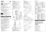
Safety Light Curtain For more information, visit http://www.ia.omron.com/f3sg-r F3SG-□RA Series Quick Installation Manual © OMRON Corporation 2014-2015 All Rights Reserved. Original instructions 7999687-9C Introduction Thank you for purchasing the F3SG-RA Series Safety Light Curtain (hereinafter referred to as the "F3SG-R"). This document contains simple instructions to install the F3SG-R. Please download the F3SG-R User's Manual for full contents of the instructions from our website at: http://www.ia.omron.com/f3sg-r Table of Contents 1. What is Included ................................................................................................................................. 1 2. Factory Default Settings ..................................................................................................................... 1 3. Ratings/Specifications ........................................................................................................................ 2 4. Input/Output Circuit ............................................................................................................................. 5 4-1. Input/Output Circuit .................................................................................................................... 5 5.Wiring Examples .................................................................................................................................. 6 5-1. Standalone F3SG-RA using PNP Outputs ................................................................................. 6 5-2. Standalone F3SG-RA using NPN Outputs ................................................................................. 6 5-3. Standard Muting Mode/Exit-Only Muting Mode using PNP Outputs .......................................... 7 5-4. Standard Muting Mode/Exit-Only Muting Mode using NPN Outputs .......................................... 7 6. DIP Switch .......................................................................................................................................... 8 7. Dimentions .......................................................................................................................................... 9 7-1. Mounted with Standard Fixed Brackets (F39-LGF) .................................................................... 9 7-2. Mounted with Standard Adjustable Brackets (F39-LGA) .......................................................... 11 8. Mounting ........................................................................................................................................... 13 8-1. Mounting with Standard Fixed Brackets (F39-LGF) ................................................................. 13 8-2. Mounting with Standard Adjustable Brackets (F39-LGA) ......................................................... 14 9. LED Indicators .................................................................................................................................. 17 10. Troubleshooting ............................................................................................................................. 19 10-1. Lockout State ......................................................................................................................... 19 10-2. Warning .................................................................................................................................. 20 11. Reference Documents .................................................................................................................... 21 1. What is Included Product F3SG-RA main unit Quantity Emitter x 1, Receiver x 1 Standard Fixed Bracket The number of brackets included depends on protective height of the F3SG-R. Less than 1,280 mm: 2 sets 1,280 mm or longer and up to 2,270 mm: 3 sets 2,350 mm or longer and up to 2,510 mm: 4 sets Warning Zone Label Troubleshooting Guide Sticker Safety Precautions Quick Installation Manual 1 1 4 1 2. Factory Default Settings Feature External Test Interlock EDM (External Device Monitoring) Auxiliary Output Muting Override Factory Default Setting 24 V Active Auto Reset Mode enabled Disabled Enabled Standard Muting Mode enabled Enabled Refer to F3SG-R Series User's Manual for more information. F3SG-RA Quick Installation Manual 1 3. Ratings/Specifications The in the model names indicate the protective heights in millimeters. F3SG-4RA-14 F3SG-2RA-14 Type of ESPE (IEC 61496-1) Type 4 Type 2 F3SG-4RA-30 F3SG-2RA-30 F3SG-4RA-14/-30 F3SG-2RA-14/-30 Performance Object Resolution (Detection Capability) Beam Gap Number of Beams Lens Size Protective Height Operating Range Response Time Opaque objects 14-mm dia. 30-mm dia. 10 mm 20 mm 15 to 207 8 to 124 5.2 x 3.4 (W x H) mm 7-mm dia. 160 to 2080 mm 190 to 2510 mm (6.3 to 81.9 inch) (7.3 to 98.7 inch) 0.3 to 10.0 m 0.3 to 20.0 m Long (1 to 32 ft.) (1 to 65 ft.) 0.3 to 3.0 m 0.3 to 7.0 m Short (1 to 10 ft.) (1 to 23 ft.) Normal mode: 8 to 18 ms *1 ON to OFF Slow mode: 16 to 36 ms *1 *2 OFF to ON 40 to 90 ms *1 *1. Response time when used in one segment system or in cascaded connection. Refer to F3SG-R Series User's Manual for more information. *2. Selectable by Configuration Tool. Effective Aperture Angle (EAA) (IEC 61496-2) Light Source Startup Waiting Time Type 4 Type 2 ±2.5° max., emitter and receiver at operating range of 3 m or greater ±5.0° max., emitter and receiver at operating range of 3 m or greater Infrared LEDs, Wavelength: 870 nm 2 s max. Electrical Power Supply Voltage (Vs) Current Consumption SELV/PELV 24 VDC±20% (ripple p-p 10% max.) Refer to F3SG-R Series User's Manual for more information. Two PNP or NPN transistor outputs (PNP or NPN is selectable by DIP Switch.) Load current of 300 mA max., Residual voltage of 2 V max. (except for voltage drop due to cable extension), Capacitive load of 1 F max., Inductive load of 2.2 H max. *1 Leakage current of 1 mA max. (PNP), 2 mA max. (NPN) *2 Safety Outputs (OSSD) Auxiliary Output Output Operation Mode 2 Safety Output Auxiliary Output *1. The load inductance is the maximum value when the safety output frequently repeats ON and OFF. When you use the safety output at 4 Hz or less, the usable load inductance becomes larger. *2. These values must be taken into consideration when connecting elements including a capacitive load such as a capacitor. One PNP or NPN transistor output (PNP or NPN is selectable by DIP Switch.) Load current of 100 mA max., Residual voltage of 2 V max . Light-ON (Safety output is enabled when the receiver receives an emitting signal.) Muting or Override output (default) (Configurable by Configuration Tool) F3SG-RA Quick Installation Manual F3SG-4RA-14 F3SG-2RA-14 F3SG-4RA-30 F3SG-2RA-30 TEST: 24 V Active: 9 V to Vs (sink current 3 mA max.) * 0 V Active: 0 to 3 V (source current 3 mA max.) MUTE A/B: ON Voltage PNP: Vs to Vs-3 V (sink current 3 mA max.) * NPN: 0 to 3 V (source current 3 mA max.) RESET: PNP: Vs to Vs-3 V (sink current 5 mA max.) * Input Voltage NPN: 0 to 3 V (source current 5 mA max.) TEST: 24 V Active: 0 to 1.5 V, or open 0 V Active: 9 V to Vs, or open OFF Voltage MUTE A/B, RESET: PNP: 0 to 1/2 Vs, or open * NPN: 1/2 Vs to Vs, or open * * The Vs indicates a supply voltage value in your environment. Overvoltage Category (IEC 60664-1) II Indicators Refer to F3SG-R Series User's Manual for more information. Protective Circuit Insulation Resistance Dielectric Strength Output short protection, Power supply reverse polarity protection 20 M or higher (500 VDC megger) 1,000 VAC, 50/60 Hz (1 min) Functional Mutual Interference Prevention (Scan Code) Cascade Connection Test Function Safety-Related Functions This function prevents mutual interference in up to two F3SG-RA systems. Number of cascaded segments: 3 max. Total number of beams: 255 max. Total sum of cable lengths between sensors: 10 m max. Self-test (at power-on, and during operation) External test (light emission stop function by test input) Interlock External device monitoring (EDM) Pre-reset Fixed blanking/Floating blanking Reduced resolution Muting/Override Scan code selection PNP/NPN selection Response time adjustment Refer to F3SG-R Series User's Manual for more information. Environmental Ambient Temperature Ambient Humidity Operating Storage Operating Storage Ambient Illuminance Degree of Protection (IEC 60529) Vibration Resistance (IEC 61496-1) Shock Resistance (IEC 61496-1) Pollution Degree (IEC 60664-1) -10 to 55°C (14 to 131°F) (non-icing) -25 to 70°C (-13 to 158°F) 35% to 85% (non-condensing) 35% to 95% Incandescent lamp: 3,000 Ix max. on receiver surface Sunlight: 10,000 Ix max. on receiver surface IP65/IP67 10 to 55 Hz, Multiple amplitude of 0.7 mm, 20 sweeps for all 3 axes 100 m/s2, 1000 shocks for all 3 axes Pollution Degree 3 Connections Type of Connection Power cable F3SG-RA Quick Installation Manual Number of Wires Cable Length Cable Diameter Minimum Bending Radius M12 connectors: 5-pin emitter and 8-pin receiver, IP67 rated when mated, Cables prewired to the sensors Emitter: 5, Receiver: 8 0.3 m 6 mm R5 mm 3 F3SG-4RA-14 F3SG-2RA-14 Cascading cable Extension cable - Single-ended cable - Double-ended cable Type of Connection Number of Wires Cable Length Cable Diameter Minimum Bending Radius Type of Connection Number of Wires Cable Length Cable Diameter Minimum Bending Radius Extension of Power Cable F3SG-4RA-30 F3SG-2RA-30 M12 connectors: 5-pin emitter and 8-pin receiver, IP67 rated when mated Emitter: 5, Receiver: 8 0.2 m 6 mm R5 mm M12 connectors: 5-pin emitter and 8-pin receiver, IP67 rated when mated Emitter: 5, Receiver: 8 Refer to F3SG-R Series User's Manual for more information. 6.6 mm R36 mm 100 m max. Material Material Weight (packaged) Housing: Aluminum Cap: PBT Front window: PMMA Cable: Oil resistant PVC Mounting Bracket: ZDC2 FE plate: SUS Refer to F3SG-R Series User's Manual for more information. Safety Precautions, Quick Installation Manual, Standard Fixed Bracket*, Troubleshooting Guide Sticker, Warning Zone Label Included Accessories 4 * The quantity of Standard Fixed Brackets included varies depending on the protective height. [F3SG-RA-14] - Protective height of 0160 to 1200: 2 sets - Protective height of 1280 to 2080: 3 sets [F3SG-RA-30] - Protective height of 0190 to 1230: 2 sets - Protective height of 1310 to 2270: 3 sets - Protective height of 2350 to 2510: 4 sets F3SG-RA Quick Installation Manual 4. Input/Output Circuit 4-1. Input/Output Circuit • PNP Output Indicator 1 Test Input Circuit Emitter Main Circuit 2 4 5 3 2 Reset input circuit 1 Muting input circuit B 4 Muting input circuit A 3 Receiver Main Circuit 2 6 +24 VDC Brown Black TEST White Not used Yellow Not used Blue Brown Yellow RESET Pink MUTE B Gray MUTE A White OSSD 2 Black OSSD 1 Red AUX Load 5 Receiver Main Circuit 1 Load 8 Indicator 7 Load Blue 0 VDC • NPN Output Indicator 1 Test Input Circuit Emitter Main Circuit 2 4 5 3 2 Reset input circuit Receiver Main Circuit 2 1 Muting input circuit B 4 Muting input circuit A 3 +24 VDC Brown Black TEST White Not used Yellow Not used Blue Brown Yellow RESET Pink MUTE B Gray MUTE A White OSSD 2 Black OSSD 1 Red AUX Load 6 Load Receiver Main Circuit 1 5 Load Indicator 8 7 F3SG-RA Quick Installation Manual Blue 0 VDC 5 5.Wiring Examples 5-1. Standalone F3SG-RA using PNP Outputs Receiver Emitter KM1 S2 S1 24 VDC: Brown OSSD2: White OSSD1: Black AUX: Red MUTE B: Pink MUTE A: Gray RESET: Yellow *1 F39-JGA-D 0 VDC: Blue 24 VDC: Brown TEST: Black Not used: Yellow Not used: White F39-JGA-L 0 VDC: Blue [DIP Switch settings] *2 Receiver: - Manual Reset Mode - EDM enabled - PNP output Emitter: - 24 V Active KM1 KM2 KM2 KM1 M KM2 +24 VDC Functional Earth S1: Test Switch S2: Lockout/Interlock Reset Switch KM1, KM2: Safety relay with forcibly guided contacts (G7SA) or magnetic contactor M: 3-phase motor *1. Also used as EDM input line. *2. The functions can be configured with the DIP Switch. Refer to 6. DIP Switch for setting with the DIP Switch. Power Supply 0 VDC Emitter Receiver 5-2. Standalone F3SG-RA using NPN Outputs KM1 24 VDC: Brown OSSD2: White OSSD1: Black AUX: Red MUTE B: Pink MUTE A: Gray RESET: Yellow *1 F39-JGA-D 0 VDC: Blue 24 VDC: Brown TEST: Black Not used: Yellow Not used: White 0 VDC: Blue F39-JGA-L [DIP Switch settings] *2 Receiver: - Manual Reset Mode - EDM enabled - NPN output Emitter: - 0 V Active KM2 KM1 S1 S2 KM2 KM1 KM2 M +24 VDC Power Supply 0 VDC 6 S1: Test Switch Functional Earth S2: Lockout/Interlock Reset Switch KM1, KM2: Safety relay with forcibly guided contacts (G7SA) or magnetic contactor M: 3-phase motor *1. Also used as EDM input line. *2. The functions can be configured with the DIP Switch. Refer to 6. DIP Switch for setting with the DIP Switch. F3SG-RA Quick Installation Manual Emitter Receiver 5-3. Standard Muting Mode/Exit-Only Muting Mode using PNP Outputs 24 VDC : Brown OSSD2 : White Emitter: - 24 V Active ML S2 *2 S1 OSSD1 : Black AUX : Red MUTE B : Pink MUTE A : Gray 0 VDC : Blue RESET : Yellow *1 F39-JGA-D 24 VDC : Brown TEST : Black Not used : Yellow Not used : White 0 VDC : Blue F39-JGA-L [DIP Swith settings] *5 Receiver: - Auto Reset Mode - EDM disabled - PNP output +24 VDC Power Supply 0 VDC S1: Test Switch S2: Lockout/Interlock Reset Switch, Override Switch or Override Functional Earth Cancel Switch ML: Muting lamp IN1 Muting Actuator *4 IN2 Safety Controller *3 *4 *1. Also used as Override input line. *2. Make sure to connect an override cancel switch to the RESET line when using the override function. Otherwise the override state may not be released by the override cancel switch, resulting in serious injury. *3. Refer to F3SG-R Series User's Manual for more information. *4. The safety controller and the F3SG-RA must share the power supply or be connected to the common terminal of the power supply. *5. Refer to Smart Muting Actuator F3W-MA Series User's Manual for more information. *6. The functions can be configured with the DIP Switch. Refer to 6. DIP Switch for setting with the DIP Switch. 5-4. Standard Muting Mode/Exit-Only Muting Mode using NPN Outputs Receiver Emitter OSSD2: White KM1 KM2 Emitter: - 0 V Active 24 VDC: Brown OSSD1: Black AUX: Red MUTE B: Pink MUTE A: Gray 0 VDC: Blue RESET: Yellow *1 F39-JGA-D 24 VDC: Brown TEST: Black Not used: Yellow Not used: White F39-JGA-L 0 VDC: Blue [DIP Switch settings] *3 Receiver: - Auto Reset Mode - EDM enabled - NPN output KM1 ML +24 VDC S1 S2 *2 S3 KM2 Power Supply S4 S5 0 VDC M KM1 KM2 S1: Test Switch S2: Override Cancel Switch S3: Lockout/Interlock Reset Switch or Override Switch S4, S5: Muting sensor KM1, KM2: Safety relay with forcibly guided contacts (G7SA) or magnetic contactor M: 3-phase motor ML: Muting lamp F3SG-RA Quick Installation Manual Functional Earth *1. Also used as Override input line. *2. Make sure to connect an override cancel switch to the RESET line when using the override function. Otherwise the override state may not be released by the override cancel switch, resulting in serious injury. *3. The functions can be configured with the DIP Switch. Refer to 6. DIP Switch for setting with the DIP Switch. 7 6. DIP Switch Receiver DIP Switch (Cover is closed) Emitter Factory Default Setting Push Swith Screw(M2.5) Communication Port When attaching the cover, tightly fasten the screws (M2.5, recommended torque: 0.35 N•m). Failure to do so may cause the cover to come loose, leading to deterioration of the protective functions. Receiver Position Function 1 Scan Code 2 External Device Monitoring (EDM) Setting Description Scan Code A (factory default setting) Scan Code B External Device Monitoring (EDM) Disabled (factory default setting) External Device Monitoring (EDM) Enabled Auto Reset (factory default setting) 3, 4 Manual Reset (Start/Restart Interlock) Interlock/Pre-Reset Pre-Reset Auto Reset (This also enables Auto Reset.) Blanking Disabled (factory default setting) 5, 6 Fixed Blanking/Floating Blanking 7 PNP/NPN Selection 8 DIP Switch/Configuration Tool Selection Fixed Blanking Enabled Floating Blanking Enabled Blanking Disabled PNP (factory default setting) NPN DIP Switch Enabled (factory default setting) Configuration Tool Enabled Emitter Position 1 Function Scan Code Setting Description Scan Code A (factory default setting) Scan Code B Short Mode (factory default setting) 2, 3 Operating Range Selection Setting Inhibited Setting Inhibited Long Mode 4 8 External Test 24 V Active (factory default setting) 0 V Active F3SG-RA Quick Installation Manual 7. Dimentions 7-1. Mounted with Standard Fixed Brackets (F39-LGF) 50.35 7-1-1. Backside Mounting 40 35 51 P 24.85 150 max 2-M5 or M6 9.2 24.85 43 33 18 150 max 6.4 51 A F D C2 (Protective height for 14mm) C1 (Protective height for 30mm) A 66 51 Standard Fixed Bracket (F39-LGF) 150 max 150 max 2-M5 or M6 F Standard Fixed Bracket (F39-LGF) 35 < Screw: M5 or M6 > [ Unit : mm ] F3SG-RA-30 Series F3SG-RA-14 Series Dimension A C1+18 Dimension A C2+48 Dimension C1 4-digit number of the type name (Protective height) Dimension C2 4-digit number of the type name (Protective height) Dimension D C1-50 Dimension D C2-20 Dimension P 20 Dimension P 10 Protective height (C1) Number of Standard Fixed Brackets Dimension F Protective height (C2) Number of Standard Dimension F Fixed Brackets 0190 to 1230 2 1000 mm max. 0160 to 1200 2 1000 mm max. 1310 to 2270 3 1000 mm max. 1280 to 2080 3 1000 mm max. 2350 to 2510 4 1000 mm max. F3SG-RA Quick Installation Manual 9 50.35 7-1-2. Side Mounting 40 35 2-M5 or M6 150 max 150 max 9.2 42.35 43 33 18 P 6.4 51 51 66 A F F D C2 (Protective height for 14mm) C1 (Protective height for 30mm) A Standard Fixed Bracket (F39-LGF) 2-M5 or M6 51 Standard Fixed Bracket (F39-LGF) 150 max 150 max 35 < Screw: M5 or M6 > [ Unit : mm ] F3SG-RA-30 Series 10 F3SG-RA-14 Series Dimension A C1+18 Dimension A C2+48 Dimension C1 4-digit number of the type name (Protective height) Dimension C2 4-digit number of the type name (Protective height) Dimension D C1-50 Dimension D C2-20 Dimension P 20 Dimension P 10 Protective height (C1) Number of Standard Fixed Brackets Dimension F Protective height (C2) Number of Standard Dimension F Fixed Brackets 0190 to 1230 2 1000 mm max. 0160 to 1200 2 1000 mm max. 1310 to 2270 3 1000 mm max. 1280 to 2080 3 1000 mm max. 2350 to 2510 4 1000 mm max. F3SG-RA Quick Installation Manual 7-2. Mounted with Standard Adjustable Brackets (F39-LGA) 50.35 7-2-1. Backside Mounting A F D C2 (Protective height for 14mm) C1 (Protective height for 30mm) A 24.85 150 max 2-M5 or M6 P 9.2 24.85 43 33 18 150 max 6.4 72 84 72 Standard Adjustable Bracket (F39-LGA) 72 2-M5 or M6 F Standard Adjustable Bracket (F39-LGA) 150 max 35 150 max 48.6 35 < Screw: M5 or M6 > [ Unit : mm ] F3SG-RA-30 Series F3SG-RA-14 Series Dimension A C1+18 Dimension A C2+48 Dimension C1 4-digit number of the type name (Protective height) Dimension C2 4-digit number of the type name (Protective height) Dimension D C1-50 Dimension D C2-20 Dimension P 20 Dimension P 10 Protective height (C1) Number of Standard Adjustable Brackets Dimension F Protective height (C2) Number of Standard Dimension F Adjustable Brackets 0190 to 1230 2 1000 mm max. 0160 to 1200 2 1000 mm max. 1310 to 2270 3 1000 mm max. 1280 to 2080 3 1000 mm max. 2350 to 2510 4 1000 mm max. F3SG-RA Quick Installation Manual 11 50.35 7-2-2. Side Mounting 48.6 35 2-M5 or M6 43 33 18 9.2 42.35 150 max P 150 max 6.4 72 72 84 A F F D C2 (Protective height for 14mm) C1 (Protective height for 30mm) A Standard Adjustable Bracket (F39-LGA) 2-M5 or M6 72 Standard Adjustable Bracket (F39-LGA) 150 max 150 max 35 < Screw: M5 or M6 > [ Unit : mm ] F3SG-RA-30 Series 12 F3SG-RA-14 Series Dimension A C1+18 Dimension A C2+48 Dimension C1 4-digit number of the type name (Protective height) Dimension C2 4-digit number of the type name (Protective height) Dimension D C1-50 Dimension D C2-20 Dimension P 20 Dimension P 10 Protective height (C1) Number of Standard Adjustable Brackets Dimension F Protective height (C2) Number of Standard Dimension F Adjustable Brackets 0190 to 1230 2 1000 mm max. 0160 to 1200 2 1000 mm max. 1310 to 2270 3 1000 mm max. 1280 to 2080 3 1000 mm max. 2350 to 2510 4 1000 mm max. F3SG-RA Quick Installation Manual 8. Mounting 8-1. Mounting with Standard Fixed Brackets (F39-LGF) Step 1. Loosen screws (M3 x 15). Hexagon socket head cap screw (M3 x 15) Fixed Bracket hook Loosen this Fig. 1 Step 2. Attach the bracket to the F3SG-R and lightely tighten the screws. <Backside mounting> <Side mounting> Optical surface of F3SG-R Optical surface of F3SG-R Loosen this Slide the hook in the groove Fixed Bracket Fixed Bracket Slide the hook in the groove Lightly tighten this Fig. 2 Step 3. Adjust the position and secure the bracket to the F3SG-R. Tightening torque: 2.0 N•m (recommended) <Backside mounting> <Side mounting> Securely tighten this Securely tighten this Adjust the bracket to mounting position Adjust the bracket to mounting position Fig. 3 F3SG-RA Quick Installation Manual 13 Step 4. Secure the bracket to the wall. <Backside mounting> Fix the Standard Fixed Bracket to the wall surface with screws <Side mounting> Fix the Standard Fixed Bracket to the wall surface with screws Fig. 4 Screws to mount the brackets to the wall are not included. 8-2. Mounting with Standard Adjustable Brackets (F39-LGA) Step 1. Step 2. Loosen the Screw (1) and adjust the angle. Loosen the Screw (2). Screw (2) (hexagon socket head cap screw (M3 x 15)) Adjustable Bracket (2) Adjustable Bracket (1) Screw (1) (hexagon socket head cap screw (M3 x 15)) hook 2. Loosen this 1. Loosen this Adjustable Bracket (3) Fig. 1 Step 3. Attach the bracket to the F3SG-R and lightely tighten the Screw (2). <Backside mounting> Screw(2) Loosen this <Side mounting> Optical surface of F3SG-R Adjustable Bracket(2) Optical surface of F3SG-R Slide the hook in the groove Adjustable Bracket(3) Screw(1) Loosen this Adjustable Bracket(1) Slide the hook in the groove Adjustable Bracket(3) Screw(2) Adjustable Bracket(2) Screw(1) Adjustable Bracket(1) Fig. 2 14 F3SG-RA Quick Installation Manual Step 4. Adjust the position and secure the bracket to the F3SG-R lightely. Tightening torque: 2.0 N•m (recommended) <Backside mounting> <Side mounting> Securely tighten this Securely tighten this Adjust the bracket to mounting position Adjust the bracket to mounting position Fig. 3 Step 5. Secure the bracket to the wall. <Backside mounting> Fix the Standard Adjustable Bracket to the wall surface with screws <Side mounting> Fix the Standard Adjustable Bracket to the wall surface with screws Fig. 4 F3SG-RA Quick Installation Manual 15 Step 6. Power the F3SG-R on and perform beam alignment. <Emitter> <Receiver> Fig. 6 Fig. 5 Angle adjustment range: ±15° Step 7. Secure the bracket to the F3SG-R. Tightening torque: 2.0 N•m (recommended) <Backside mounting> Securely tighten this <Side mounting> Securely tighten this <Enlarged view> Securely tighten this Screw(1) (Hexagon socket head cap screw (M3x15)) Fig. 7 16 F3SG-RA Quick Installation Manual 9. LED Indicators <Emitter> <Receiver> 1. Top-beam-state indicator (Blue) 2. PNP/NPN mode indicator (Green) 3. Response time indicator (Green) 4. Sequence error indicator (Yellow) 5. Blanking indicator (Green) 6. Configuration indicator (Green) 1. Test indicator (Green) 2. Operating range indicator (Green) 7. Interlock indicator (Yellow) 8. External device monitoring indicator (Green) 3. Power indicator (Green) 9. Internal error indicator (Red) 4. Lockout indicator (Red) 10. Lockout indicator (Red) 11. Stable-state indicator (Green) 12. ON/OFF indicator (Green/Red) 13. Communication indicator (Green) 14. Bottom-beam-state indicator (Blue) F3SG-RA Quick Installation Manual 17 LED Indicator Status Emitter Location 1 Test Name of Indicator TEST Color Green Illuminated - 2 Operating range LONG Green Long range mode is selected 3 4 Power Lockout POWER LOCKOUT Green Red Power is ON. - Blinking External Test is being performed Lockout state due to DIP Switch setting error or Operating range selection setting error Error due to noise Lockout state due to error in emitter Receiver Location Name of Indicator Color 1 Top-beam-state TOP Blue 2 PNP/NPN mode NPN Green 3 Response time SLOW Green 4 Sequence error SEQ Yellow 5 Blanking BLANK Green 6 Configuration CFG Green 7 Interlock External device monitoring 8 Illuminated The top beam is unblocked Blinking Muting/Override state, or Lockout state due to Cap error or Other sensor error INT-LK Yellow NPN mode is selected by DIP Switch Response Time Adjustment is enabled Sequence error in Muting or Pre-reset mode Blanking, Warning Zone or Teach-in mode, or Blanking Monitoring error Reduced Resolution is enabled Teach-in mode, zone measurement being performed by Dynamic Partial Muting, or Lockout state due to Parameter error or Cascading Configuration error Interlock state Pre-reset mode *2 EDM Green RESET input is in ON state *1 Lockout state due to EDM error INTERNAL Red 9 Internal error 10 Lockout LOCKOUT Red 11 Stable-state STB Green 12 ON/OFF ON/OFF 13 Communication COM 14 Bottom-beam-state BTM Green Red Green Blue Lockout state due to Internal error, or error due to abnormal power supply or noise Lockout state due to error in receiver Incident light level is 170% or Safety output is instantaneously turned OFF due higher of ON-threshold to ambient light or vibration Safety output is in ON state Safety output is in OFF state, or Lockout state due to Safety Output error, or error the sensor is in Setting state due to abnormal power supply or noise Synchronization between emitter Lockout state due to Communication error, or and receiver is maintained error due to abnormal power supply or noise Muting/Override state, or Lockout state due to The bottom beam is unblocked DIP Switch setting error - *1.The EDM indicator is illuminated when the RESET input is in the ON state regardless of the use of the EDM function. *2.Refer to F3SG-R Series User's Manual for more information. TOP, CFG, LOCKOUT, STB and ON/OFF indicators are illuminated when the receiver is in Setting mode. 18 F3SG-RA Quick Installation Manual 10. Troubleshooting Lockout State Blink <Indicator status at lockout: Receiver> <Indicator status at lockout: Emitter> Combination of Indicators and Error Description Combination of Indicators and Error Description TOP LOCKOUT Blinking Once LOCKOUT [Error Description] Cap error Other sensor error BLANK Blanking monitoring error CFG Cascading configuration error EDM External device monitoring error INTERNAL COM Communication error BTM DIP Switch setting error ON OFF Safety output error due to power supply voltage or noise INTERNAL POWER Other sensor error Cascading configuration error Internal error Communication error POWER Internal or communication error due to noise LOCKOUT Blinking Twice Warning Safety output error Blinking Twice Blinking Once [Error Description] DIP Switch setting error Operating range selection setting error LONG Internal error ON OFF COM LOCKOUT OFF Communication error due to power supply voltage or noise Internal error due to power supply voltage or noise <Indicator status at warning: Receiver> Combination of indicators and Error Description LOCKOUT SEQ [Warning Description] Malfunction due to ambient light or vibration STB *1 Muting sequence error or Interlock sequence error *1 There are several illumination patterns to identify a faulty sequcence. <Indicator status at warning: Emitter> None 10-1. Lockout State Description Cap error Other sensor error Blanking monitoring error Cascading configuration error External device monitoring error Internal error Safety output error Communication error DIP Switch setting error Operating range selection setting error F3SG-RA Quick Installation Manual Cause and measures A cap may be detached. Attach the cap properly. Other sensor being cascaded caused an error. Check the indicator of the sensor. An error is detected by the fixed blanking monitoring function or the floating blanking monitoring function. The cascading cable may be short-circuited, broken, or disconnected. Check that the cascading cable should be tightly connected. If the cascading cable is broken, replace it. The number of connected sensors or beams may have exceeded the maximum value due to cascading. Check the configuration. Relay may be welded. Replace the relay. The relay and the RESET line may not be properly wired. Check the wiring with the relay. The relay response time may be exceeding the allowable delay time. Change the allowable delay time or replace the relay with one that has an appropriate response time. An error may have occurred in the internal circuit. Replace the F3SG-R. Safety output lines may be short-circuited to each other or another signal line may be short-circuited to the safety output line. Wire the safety output lines properly. The communication line or other wiring may be broken or short-circuited. Check the Cascading or extension cables. If the wiring is extended with cables other than specified, the cables used for extension may not have performance equivalent or greater than the specified cables. Use cables with the same performance or more than the specified cables. A DIP Switch may have been changed during operation. Check if a DIP Switch Setting was changed or not. Settings of two DIP Switches of a receiver may be unmatched. Check if two DIP Switches of a receiver are matched. The setting of the operating range selection may be incorrect. Check if the Operating Range Selection of the DIP Switch is properly set. 19 Description Safety output error due to power supply voltage or noise Cause and measures The power supply voltage may have dropped temporarily when the F3SG-R is in operation. Check for temporary power supply voltage drop (by about 12 VDC) by the influence of the inductive load, etc. If the exclusive power supply is not used, check the power consumption of other connected devices for enough capacity. Effect of noise may be excessive. If other devices using the same power supply generate noise, do not share the same power supply with other devices, and use a separate power supply exclusively for the safety components. The inductive noise tends to be induced especially if the power supply line of the machine guarded and the power supply line of the F3SG-R are arranged in parallel. Arrange the exclusive power supply near the F3SG-R or lay the power supply line of the F3SG-R away from the power supply line of the machine guarded. If the power supply for the F3SG-R is located near the power supply of the machine guarded and it uses the same ground, it is subject to the influence of common mode noise from the ground. Separate the grounding point or use it as the exclusive ground. Power supply voltage may be outside the rated range. Connect the F3SG-R to a 24 VDC±20% power supply voltage. Voltage fluctuation may have occurred due to insufficient power supply capacity. Replace the power supply with one that has a larger capacity. Instantaneous break or instantaneous stop may have occurred due to power sharing with other devices. Do not share the power supply with other devices. Connect the F3SG-R to a power supply that is dedicated to electro-sensitive protective devices for electro-sensitive protective equipment such as the F3SG-R, safety controller, etc. Communication error due to power Communication error may have occurred due to noise. supply voltage or noise Check the noise level in the environment. The power supply voltage may have dropped temporarily when the F3SG-R is in operation. Check for temporary power supply voltage drop (by about 12 VDC) by the influence of the inductive load, etc. If the exclusive power supply is not used, check the power consumption of other connected devices for enough capacity. Internal error due to power supply The internal circuitry may be defective due to power supply voltage or noise. voltage or noise Check the ambient noise environment. Make sure that the power supply voltage is 24 VDC±20%. If the indicator still shows this error, replace the F3SG-R. Internal or communication error The internal circuitry may be defective due to noise. Check the noise level in the environment. due to noise Communication error may have occurred due to noise. Check the noise level in the environment. 10-2. Warning Description Malfunction due to ambient light or vibration Muting sequence error Interlock sequence error Cause and measures An instantaneous beam shift may have occurred due to vibration or ambient light. Check the installation condition. Take necessary measures against mutual interference according to "Mutual Interference Prevention ". Muting input may have been applied in the incorrect order. The cause of a muting error can be determined according to the indicator display patterns. An input related to interlock may have been applied in an incorrect sequence. A cause of an interlock error can be recognized by an indication pattern of indicators. Muting Sequence Error Indication Sequence error indicator Blinking: Once 20 Cause and measures Power supply may have been turned ON with muting input A or B being ON. Check the condition of the muting sensors and light curtains. muting input B may have been turned ON before muting input A was turned ON. Check the condition of the muting sensors. muting input A and B may have been turned ON at the same time. Check the arrangement of the muting sensors. Check if the wiring of muting input A and B is short-circuited. Either muting input A or B may have been turned ON with the light curtain being blocked or in Interlock State. Check the condition of the light curtains. F3SG-RA Quick Installation Manual Sequence error indicator Cause and measures muting input B may have been turned ON within T1min (= 0.1 s *1) after muting input A was turned ON. Check that if the muting sensors are installed too close each other. Check that if the speed of the workpiece is too fast. *1 Factory default setting It may have taken T1max (= 4 s *1) or longer for muting input B to be turned ON after muting input A was turned ON. Blinking: Twice Check that if the muting sensors are installed too far each other. Check that if the speed of the workpiece is too slow. *1 Factory default setting The light curtain may have been blocked after muting input A was turned ON but before muting input B was turned ON. Check the condition of the light curtains. The light curtain may have been blocked within 0.08 s after muting input A and B were normally turned ON. Check that if the muting sensor and light curtain are installed too close each other. Check that if the speed of the workpiece is too fast. Blinking: Four times Muting may have been released after the light curtain entered the muting state but before a workpiece blocked the light curtain. Check that the workpiece still remains. Check that the speed of the workpiece is too slow. The light curtain entered the muting state, but muting may have then been released while a workpiece passes through the light curtain. Check that the workpiece still remains. Blinking: Five times Check that if the speed of the workpiece is too slow. Check that the muting sensors have been installed upstream and downstream of the light curtain with the size of workpieces taken into account. (Using four muting sensors) Muting may have been released with muting input A and B remained ON after a workpiece passed through the light curtain. Blinking: Six times Check that the workpiece still remains. Check that the speed of the workpiece is too slow. The next muting sequence may have started after muting was released but before the initial muting condition was established. Blinking: Seven times Check that if a next workpiece has not entered before the current workpiece passes through the light curtain. Check that if the interval between workpieces are too narrow. Interlock Sequence Error Indication Sequence error indicator Cause and measures The reset or pre-reset switch may have been pressed before the light curtain receives light. Check the reset input and pre-reset input wiring. The light curtain may have been interrupted or the pre-reset switch may have been pressed before the pre-reset switch is pressed. Check the light curtain status and pre-reset input wiring. After the pre-reset switch was pressed, the pre-reset or reset switch may have been pressed before the light curtain is interrupted. Check the installation environment of the light curtain. Blinking: Once Blinking: Twice Blinking: Three times After the pre-reset switch was pressed and the light curtain was interrupted, the pre-reset switch may have been pressed before the reset switch is pressed. Check the pre-reset input wiring. After the pre-reset switch was pressed, a time period from interruption of the light curtain to the reset switch being pressed may have exceeded the allowable time. Check the installation environment of the light curtain as well as pre-reset and reset switches. The number of interruptions of the light curtain may have exceeded the allowable value after the prereset switch was pressed and before the reset switch is pressed. Check the installation environment of the light curtain. 11. Reference Documents Document Title Safety Light Curtain F3SG-R Series User's Manual Language English Japanese Italian Simplified Chinese Cat. No. Z352-E1 SGFM-712 Z352-IT1 Z352-CN1 Please download the F3SG-R User's Manual for full contents of the instructions from our website at: http://www.ia.omron.com/f3sg-r F3SG-RA Quick Installation Manual 21 Suitability for Use Omron Companies shall not be responsible for conformity with any standards, codes or regulations which apply to the combination of the Product in the Buyer’s application or use of the Product. At Buyer’s request, Omron will provide applicable third party certification documents identifying ratings and limitations of use which apply to the Product. This information by itself is not sufficient for a complete determination of the suitability of the Product in combination with the end product, machine, system, or other application or use. Buyer shall be solely responsible for determining appropriateness of the particular Product with respect to Buyer’s application, product or system. Buyer shall take application responsibility in all cases. NEVER USE THE PRODUCT FOR AN APPLICATION INVOLVING SERIOUS RISK TO LIFE OR PROPERTY WITHOUT ENSURING THAT THE SYSTEM AS A WHOLE HAS BEEN DESIGNED TO ADDRESS THE RISKS, AND THAT THE OMRON PRODUCT(S) IS PROPERLY RATED AND INSTALLED FOR THE INTENDED USE WITHIN THE OVERALL EQUIPMENT OR SYSTEM. See also Product catalog for Warranty and Limitation of Liability. OMRON Corporation Industrial Automation Company (Manufacturer) Shiokoji Horikawa, Shimogyo-ku, Kyoto, 600-8530 JAPAN Regional Headquarters OMRON EUROPE B.V. (Representative and Importer in EU) Wegalaan 67-69, NL-2132 JD Hoofddorp THE NETHERLANDS Tel: (31)-2356-81-300 / FAX: (31)-2356-81-388 OMRON SCIENTIFIC TECHNOLOGIES INC. 6550 Dumbarton Circle Fremont, CA 94555 U.S.A. Tel: (1) 510-608-3400 / Fax: (1) 510-744-1442 Contact: www.ia.omron.com OMRON ASIA PACIFIC PTE. LTD. No. 438A Alexandra Road # 05-05/08 (Lobby 2), Alexandra Technopark, Singapore 119967 Tel: (65) 6835-3011 / Fax: (65) 6835-2711 OMRON (CHINA) CO., LTD. Room 2211, Bank of China Tower, 200 Yin Cheng Zhong Road, PuDong New Area, Shanghai, 200120, China Tel: (86) 21-5037-2222 / Fax: (86) 21-5037-2200 In the interest of product improvement, specifications are subject to change without notice. 22 F3SG-RA Quick Installation Manual