1
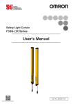
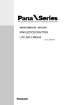
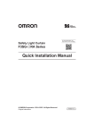
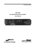
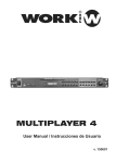
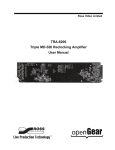
F3W-MA Smart Muting Actuator ustness Combine with F3SG-R Safety Light Curtains » Compact: Easy installation » Robust: Even in severe environments » Global: Reliable safety solutions New muting functionality Increases both productivity and safety Easily distinguishes between workers and objects Increasing both productivity and safety The F3SG-R provides advanced muting function that detects the zone where workpieces pass or the position of a machine or robot and disable beams of the detected part. This increases both safety and productivity. By adding the smart muting actuator, the F3SG-R provides stable operation even for the production lines where errors occur due to vibration caused by the passing workpiece. Previously… Smart muting actuator reduces adjustment time by 80%* The use of the dedicated actuator can significantly reduce the time required to adjust the sensor to detect workpieces even in unstable conveying conditions. *Compared to the previous model (Based on OMRON investigation in September 2014) Smart muting actuator Previous model ■ Installation ■ Wiring ■ Adjustment F3SG-R The point detection muting sensor mistakenly disabled muting while a workpiece was passing, which led to unexpected machine stops. ■ Troubleshooting ■ Maintenance Reduced by 80% 0 10 Previously… 20 30 40 50 60 70 80 90 100 Many processes including programming and adjustment were required Since bypass processing to disable the safety light curtain was performed via the PLC, F3SG PLC programming before installation The muting actuator detects the surface of a passing workpiece. Even if a workpiece moves due to vibration, muting is kept enabled until the workpiece has passed. This prevents unexpected machine stops. required time and work. It also took a lot of time and work to install and adjust many muting B1 Reflector A2 Sensor A1 sensors (sensors and reflectors). 5 Powerful features Prevent unexpected machine stops Ensure stable operation Auto-configuration of muting zone When workpieces with various heights are conveyed on the same line, partial muting is automatically performed based on the height of the workpiece. This advanced muting function can automatically perform normal detection at the zone where a workpiece does not pass. Automatically minimizes muting zone according to workpiece size 1 When the muting sensor detects that a workpiece passes, all beams are muted. Minimizing setting and detection errors 2 The only beams interrupted by the workpiece are kept muted and The function to log the muting sensor operating conditions of the F3SG-R visualizes the installation position and setting conditions of the sensor to achieve reliable configuration. The stop due to the muting error can be analyzed using the data stored in the F3SG-R. Quick identification of the cause can reduce unexpected machine downtime. other beams are released from the muting state three seconds after the workpiece pass through the safety light curtain. Muting is disabled after the workpiece has passed. Monitors human entry into the zone where a workpiece does not pass. Keeps the zone muted when a workpiece passes. Visualized data makes adjustment smooth! 6 Smart Muting Actuator F3W-MA Integrated muting sensor based on multi-beam photoelectric sensor • A muting system can be configured easily in combination with the F3SG safety light curtain. • Muting functions can be stably performed even when workpieces with holes pass. Ordering Information Smart Muting Actuator Beam Gap between Muting Trigger Beams Number of Beams F3W-MA0100P 100mm 8 F3W-MA0300P 300mm 20 Appearance Model Accessories (Sold separately) Single-ended Connector Cable Appearance Type For emitter For receiver 4 Cable length Model 3m F39-JG3A-L 7m F39-JG7A-L 10 m F39-JG10A-L 15 m F39-JG15A-L 20 m F39-JG20A-L 3m F39-JG3A-D 7m F39-JG7A-D 10 m F39-JG10A-D 15 m F39-JG15A-D 20 m F39-JG20A-D Specifications Emitter cable:M12 connector (5-pin), 5 wires Color: Gray M12 connector (8-pin), 8 wires Color: Black F3W-MA Double-ended Cable Appearance Type Cable length 0.5 m For emitter For receiver Model Specifications F39-JGR5B-L 1m F39-JG1B-L 3m F39-JG3B-L 5m F39-JG5B-L 7m F39-JG7B-L 10 m F39-JG10B-L 15 m F39-JG15B-L 20 m F39-JG20B-L 0.5 m F39-JGR5B-D 1m F39-JG1B-D 3m F39-JG3B-D 5m F39-JG5B-D 7m F39-JG7B-D 10 m F39-JG10B-D 15 m F39-JG15B-D 20 m F39-JG20B-D M12 connector (5-pin) on both ends Color: Gray M12 connector (8-pin) on both ends Color: Black Sensor Mounting Brackets Appearance Specification Model Standard Fixed Bracket F39-LGF Bracket to mount the F3W-MA. Side mounting and backside mounting possible. Two brackets per set F39-LGA Bracket to mount the F3W-MA. Beam alignment after mounting possible.The angle adjustment range is ±15°. Side mounting and backside mounting possible. Two brackets per set Standard Adjustable Bracket Application Remarks 5 F3W-MA Ratings/Specifications F3W-MA0100P Performance Beam Gap between Muting Trigger Beams Number of Beams Standard Detection Object Long Operating Range Short Operation Response Time Reset Effective Aperture Angle Light Source Startup Waiting Time Power Supply Voltage (Vs) Emitter Current Consumption Receiver Electrical Input Voltage 100mm 300mm 8 20 30mm 0.3 to 20.0 m (1 to 65 ft.) 0.3 to 7.0 m (1 to 23 ft.) 13 ms max. 26 ms max. (Synchronized) 78 ms max. (Not synchronized) ±2.5° max., emitter and receiver at operating range of 3 m or greater Infrared LEDs, Wavelength: 870 nm 2 s max. SELV/PELV 24 VDC±20% (ripple p-p 10% max.) 35mA 45mA 75mA 75mA Two PNP transistor outputs. Load current of 300 mA max., Residual voltage of 2 V max. (except for voltage drop due to cable extension)j Muting Outputs Output Operation Mode F3W-MA0300P Muting Output A Dark-ON (Muting Output A is enabled when MuteA trigger beam is blocked.) Muting Output B Dark-ON (Muting Output B is enabled when MuteB trigger beam is blocked.) ON Voltage [MuteEnable] Vs to Vs-3 V (sink current 5 mA max.) * OFF Voltage [Mute Enable] 0 to 1/2 Vs, or open * * The Vs indicates a supply voltage value in your environment. Indicators Protective Circuit Insulation Resistance Dielectric Strength Functional Ambient Humidity Environmental Connections 6 20 MΩ or higher (500 VDC megger) 1,000 VAC, 50/60 Hz (1 min) - Scan Code Selection - Operation Mode Selection (Point to Point Detection/ Chattering and Void Space Prevention) - Off-Delay - Muting Enable - Muting Trigger Beam Allocation - Operating Range Selection Functions Ambient Temperature Refer to page 40. LED Indicator Status Protective Circuit Output short protection, Power supply reverse polarity protection Operating Storage Operating Storage -10 to 55°C (13 to 131°F) (non-icing) -25 to 70°C (-13 to 158°F) 35% to 85% (non-condensing) 35% to 95% Ambient Illuminance Incandescent lamp: 3,000 Ix max. on receiver surface Sunlight: 10,000 Ix max. on receiver surface Degree of Protection (IEC 60529) Vibration Resistance (IEC 61496-1) Shock Resistance (IEC 61496-1) Pollution Degree (IEC 60664-1) IP65/IP67 Extension of Power Cable 100 m max. Note: For T-Shaped configuration with COM lines, the length of cable extension is 30m max. 10 to 55 Hz, Multiple amplitude of 0.7 mm, 20 sweeps for all 3 axes 100 m/s2, 1000 shocks for all 3 axes Pollution Degree 3 Material Housing: Aluminum, Cap: PBT, Front Window: PMMA, Cable: Oil resistant PVC, FE plate: SUS Weight (packaged) Included Accessories 1.8 kg max. Instruction Sheet 2.8 kg max. F3W-MA LED Indicator Status Shown below are indication statuses of F3W-MA LED indicators when you purchased. Emitter Name of Indicator Color Illuminated Operating range LONG Green Long Range mode is selected by DIP Switch. Running RUN Green Power is ON. Error ERR Red Blinking - - Error in emitter. Generic error happens. Receiver Name of Indicator Top-beam-state TOP Muting output A Color Illuminated Blinking Blue The top beam is unblocked. - MUTE A Green Muting Output A is activated. - Muting output B MUTE B Green Muting Output B is activated. - Off-Delay DELAY Yellow Off-Delay function is enabled by DIP Switch. - Chattering/ Void space CHAT Green Chattering and Void Space Prevention mode is selected by DIP Switch. - Muting Enable MUTE DISABLE Red The Muting Enable function is enabled and Muting Enable input is turned OFF by DIP Switch. - Error ERR Red - Stable-state STB Green Incident light level is 170% or higher of ON-threshold Running RUN Green Power is ON. Communication COM Green Bottom-beamstate BTM Blue Synchronization between emitter and receiver is maintained. The bottom beam is unblocked. Error in receiver. Generic error happens. [Primary sensor] - Start-up (for approx. 3 s) - Synchronization between emitter and receiver is lost - 7 F3W-MA Wiring Examples Standard Muting Mode with F3SG-R (T-Shaped Configuration with COM lines) +24 VDC 0 VDC Power Supply CFG In: Black COM+: White COM-: Yellow 0 VDC: Blue F39-JG@A-L Functional Earth COM-: Yellow Functional Earth COM+: White CFG In *2: Black 24 VDC: Brown 0 VDC: Blue F3W-MA Emitter (Secondary) 24 VDC: Brown F3W-MA Emitter (Primary) F39-JG@A-L [DIP Switch settings (F3SG-RA)] Scan Code: Code A [DIP Switch settings (F3W-MA-Primary)] Scan Code: Code B [DIP Switch settings (F3W-MA-Secondary)] Not used F3SG-RA Emitter *1 [Emitter] *1. Signal wiring of the F3W-MA is not required. *2. Do not connect CFG In line to +24 VDC line. Otherwise, F3W-MA enters the error state. [Receiver] +24 VDC 0 VDC Note 1. For the wiring of safety light curtains such as F3SG-R, refer to the applicable user's manual separately. Note 2. For devices connecting to the F3W-MA, the same power supply must be used. 8 Power Supply 0 VDC: Blue 24 VDC: Brown CFG Out: Red COM+: Gray COM-: Pink CFG In: Yellow F39-JG@A-D Functional Earth Muting output B: White Muting output B: White Muting output A: Black COM-: Pink Functional Earth COM+: Gray CFG Out: Red Mute Enable: Yellow 24 VDC: Brown 0 VDC: Blue F39-JG@A-D F3W-MA Receiver (Secondary) Muting output A: Black F3W-MA Receiver (Primary) MUTE A MUTE B F3SG-RA Receiver [DIP Switch settings (F3SG-RA)] Scan Code: Code A [DIP Switch settings (F3W-MA-Primary)] Scan Code: Code B Muting Enable: Disabled [DIP Switch settings (F3W-MA-Secondary)] Not used F3W-MA Exit-Only Muting Mode with F3SG-R (L-Shaped Configuration) F3SG-RA Emitter *1 [Emitter] F3W-MA Emitter [DIP Switch settings (F3W-MA)] Scan Code: Code A +24 VDC 0 VDC Power Supply COM-: Yellow Functional Earth COM+: White CFG *2: Black 24 VDC: Brown 0 VDC: Blue F39-JG@A-L [DIP Switch settings (F3SG-RA)] Scan Code: Code B *1. Signal wiring of the F3W-MA is not required. *2. Do not connect CFG In line to +24 VDC line. Otherwise, F3W-MA enters the error state. F3SG-RA Receiver [Receiver] MUTE A Muting Enable: Enabled Muting output B: White Muting output A: Black COM-: Pink Functional Earth COM+: Gray CFG Out: Red Mute Enable: Yellow 24 VDC: Brown 0 VDC: Blue F39-JG@A-D MUTE B F3W-MA Receiver [DIP Switch settings (F3SG-RA)] Scan Code: Code B [DIP Switch settings (F3W-MA)] Scan Code: Code A +24 VDC 0 VDC S1: Mute Enable Switch Power Supply S1 Note 1. For the wiring of safety light curtains such as F3SG-R, refer to the applicable user's manual separately. Note 2. For devices connecting to the F3W-MA, the same power supply must be used. 9 F3W-MA Standard Muting Mode with Other Safety Component(T-Shaped Configuration) +24 VDC 0 VDC Power Supply CFG In: Black COM+: White COM-: Yellow 0 VDC: Blue F39-JG@A-L Functional Earth COM-: Yellow Functional Earth COM+: White CFG In: Black 24 VDC: Brown 0 VDC: Blue F3W-MA Emitter 2 24 VDC: Brown F3W-MA Emitter 1 F39-JG@A-L [SLC settings] - Muting system - Emitters and receivers of F3W-MA and SLC mounted in alternation [DIP Switch settings (F3W-MA-1)] Scan Code: Code A [DIP Switch settings (F3W-MA-2)] Scan Code: Code B Safety Light Curtain (SLC) Receiver *1 [Emitter] *1. Signal wiring of the F3W-MA is not required. [Receiver] Safety Light Curtain (SLC) Emitter *1 [SLC settings] - Muting system - Emitters and receivers of F3W-MA and SLC mounted back-to-back [DIP Switch settings (F3W-MA-1)] Scan Code: Code A Muting Enable: Enabled [DIP Switch settings (F3W-MA-2)] Scan Code: Code B F3W-MA Receiver 2 0 VDC: Blue CFG Out: Red COM+: Gray COM-: Pink Muting output A: Black Muting output B: White 24 VDC: Brown F39-JG@A-D Functional Earth Muting output B: White Muting output A: Black COM-: Pink Functional Earth COM+: Gray CFG Out: Red Mute Enable: Yellow 24 VDC: Brown 0 VDC: Blue F39-JG@A-D Mute Enable: Yellow F3W-MA Receiver 1 +24 VDC 0 VDC S1: Mute Enable Switch IN1 IN2 Safety Controller *2 *1. Signal wiring of the F3W-MA is not required. *2. Connectable Safety Control Units: NE1A and G9SP series with a muting function Note 1. For the wiring of safety light curtains such as F3SG-R, refer to the applicable user's manual separately. Note 2. For devices connecting to the F3W-MA, the same power supply must be used. 10 Power Supply S1 F3W-MA Input/Output Circuit The entire circuit diagram of the F3W-MA is shown below. The numbers in the circles indicate the connector's pin numbers. Indicator 1 +24 VDC Brown Emitter Main Circuit 3 2 Muting Enable input circuit Receiver Main Circuit 2 1 6 Blue Brown Yellow Muting Enable White Muting Output B Load 5 Black Muting Output A Receiver Main Circuit 1 Load Indicator 7 Blue 0 VDC 11 F3W-MA Mounted with Standard Adjustable Brackets (F39-LGA) 50.35 Mounted with Standard Adjustable Brackets (F39-LGA) Backside Mounting 48.6 35 35 A C1 2-M5 or M6 24.85 18 P 24.85 150 max 9.2 43 150 max 6.4 72 84 Standard Adjustable Bracket (F39-LGA) 72 A D 72 150 max 2-M5 or M6 150 max Standard Adjustable Bracket (F39-LGA) < Screw: M5 or M6 > 12 Model F3W-MA0100P Dimension A 208 F3W-MA0300P 478 Dimension C1 190 430 Dimension D 140 410 Dimension P 20 20 Number of Standard Adjustable Brackets 2 2 (Unit : mm)j F3W-MA 50.35 Side Mounting 48.6 2-M5 or M6 150 max 150 max 2-M5 or M6 150 max 35 35 9.2 18 43 42.35 150 max P 6.4 72 72 Standard Adjustable Bracket (F39-LGA) 84 A A C1 D 72 Standard Adjustable Bracket (F39-LGA) < Screw: M5 or M6 > Model F3W-MA0100P F3W-MA0300P Dimension A 208 478 Dimension C1 190 430 Dimension D 140 410 Dimension P 20 20 Number of Standard Adjustable Brackets 2 2 Standard Adjustable Bracket(F39-LGA) 42 Material: ZDC2, Fluorine-containing lubricant 45.1 34.5 31.8 9.2 8 32.9 84 6.4 72 13 F3W-MA 50.35 Mounted with Standard Fixed Brackets (F39-LGF) Backside Mounting 40 2-M5 or M6 6.4 51 66 Standard Fixed Bracket (F39-LGF) 51 A A C1 D 51 Standard Fixed Bracket (F39-LGF) 150 max 35 150 max 35 18 P 43 150 max 24.85 24.85 < Screw: M5 or M6 > 14 Model F3W-MA0100P F3W-MA0300P Dimension A 208 478 Dimension C1 190 430 Dimension D 140 410 Dimension P 20 20 Number of Standard Fixed Brackets 2 2 150 max 2-M5 or M6 9.2 F3W-MA 50.35 Side Mounting 40 150 max 2-M5 or M6 150 max 35 35 6.4 51 51 Standard Fixed Bracket (F39-LGF) 66 A A C1 D 51 Standard Fixed Bracket (F39-LGF) 18 150 max P 43 42.35 150 max 2-M5 or M6 9.2 < Screw: M5 or M6 > Model F3W-MA0100P F3W-MA0300P Dimension A 208 478 Dimension C1 190 430 Dimension D 140 410 Dimension P 20 20 Number of Standard Fixed Brackets 2 2 15 F3W-MA Standard Fixed Bracket(F39-LGF) 36 (25.8) (23.1) 8 9.2 32.1 66 6.4 Material: ZDC2 51 Accessories Single-Ended Cable for Emitter (F39-JGA-L, sold separately) L dia.14.9 40.7 Insulated vinyl round cable dia. 6.6, 5-wire (Cross section of conductor: 0.38 mm2/insulator diameter: dia. 1.2 mm) M12 IP67 connector Single-Ended Cable for Receiver (F39-JGA-D, sold separately) L dia.14.9 40.7 Insulated vinyl round cable dia. 6.6, 8-wire (Cross section of conductor: 0.38 mm2/insulator diameter: dia. 1.2 mm) M12 IP67 connector Emitter cable (Gray) 16 Receiver cable (Black) L (m) F39-JG3A-L F39-JG3A-D F39-JG7A-L F39-JG7A-D 3 7 F39-JG10A-L F39-JG10A-D 10 F39-JG15A-L F39-JG15A-D 15 F39-JG20A-L F39-JG20A-D 20 F3W-MA Double-ended Cable for Emitter: Cable for extension (F39-JGB-L, sold separately) L 44.7 dia.14.9 dia.14.9 40.7 M12 IP67 connector Emitter cable (Gray) M12 IP67 connector Insulated vinyl round cable dia. 6.6, 5-wire (2-pair + 1) (Cross section of conductor: 0.38 mm2/insulator diameter: dia. 1.2 mm) Receiver cable (Black) L (m) F39-JGR5B-L F39-JGR15B-D F39-JG1B-L F39-JG1B-D 0.5 1 F39-JG3B-L F39-JG3B-D 3 F39-JG5B-L F39-JG5B-D 5 F39-JG7B-L F39-JG7B-D 7 F39-JG10B-L F39-JG10B-D 10 F39-JG15B-L F39-JG15B-D 15 F39-JG20B-L F39-JG20B-D 20 Related Manuals ManNo. Z355 Model F3W-MA Manual name Smart Muting Actuator F3W-MA Series User's Manual 17 Terms and Conditions of Sale 1. Offer; Acceptance. These terms and conditions (these "Terms") are deemed part of all quotes, agreements, purchase orders, acknowledgments, price lists, catalogs, manuals, brochures and other documents, whether electronic or in writing, relating to the sale of products or services (collectively, the "Products") by Omron Electronics LLC and its subsidiary companies (“Omron”). Omron objects to any terms or conditions proposed in Buyer’s purchase order or other documents which are inconsistent with, or in addition to, these Terms. 2. Prices; Payment Terms. All prices stated are current, subject to change without notice by Omron. Omron reserves the right to increase or decrease prices on any unshipped portions of outstanding orders. Payments for Products are due net 30 days unless otherwise stated in the invoice. 3. Discounts. Cash discounts, if any, will apply only on the net amount of invoices sent to Buyer after deducting transportation charges, taxes and duties, and will be allowed only if (i) the invoice is paid according to Omron’s payment terms and (ii) Buyer has no past due amounts. 4. Interest. Omron, at its option, may charge Buyer 1-1/2% interest per month or the maximum legal rate, whichever is less, on any balance not paid within the stated terms. 5. Orders. Omron will accept no order less than $200 net billing. 6. Governmental Approvals. Buyer shall be responsible for, and shall bear all costs involved in, obtaining any government approvals required for the importation or sale of the Products. 7. Taxes. All taxes, duties and other governmental charges (other than general real property and income taxes), including any interest or penalties thereon, imposed directly or indirectly on Omron or required to be collected directly or indirectly by Omron for the manufacture, production, sale, delivery, importation, consumption or use of the Products sold hereunder (including customs duties and sales, excise, use, turnover and license taxes) shall be charged to and remitted by Buyer to Omron. 8. Financial. If the financial position of Buyer at any time becomes unsatisfactory to Omron, Omron reserves the right to stop shipments or require satisfactory security or payment in advance. If Buyer fails to make payment or otherwise comply with these Terms or any related agreement, Omron may (without liability and in addition to other remedies) cancel any unshipped portion of Products sold hereunder and stop any Products in transit until Buyer pays all amounts, including amounts payable hereunder, whether or not then due, which are owing to it by Buyer. Buyer shall in any event remain liable for all unpaid accounts. 9. Cancellation; Etc. Orders are not subject to rescheduling or cancellation unless Buyer indemnifies Omron against all related costs or expenses. 10. Force Majeure. Omron shall not be liable for any delay or failure in delivery resulting from causes beyond its control, including earthquakes, fires, floods, strikes or other labor disputes, shortage of labor or materials, accidents to machinery, acts of sabotage, riots, delay in or lack of transportation or the requirements of any government authority. 11. Shipping; Delivery. Unless otherwise expressly agreed in writing by Omron: a. Shipments shall be by a carrier selected by Omron; Omron will not drop ship except in “break down” situations. b. Such carrier shall act as the agent of Buyer and delivery to such carrier shall constitute delivery to Buyer; c. All sales and shipments of Products shall be FOB shipping point (unless otherwise stated in writing by Omron), at which point title and risk of loss shall pass from Omron to Buyer; provided that Omron shall retain a security interest in the Products until the full purchase price is paid; d. Delivery and shipping dates are estimates only; and e. Omron will package Products as it deems proper for protection against normal handling and extra charges apply to special conditions. 12. Claims. Any claim by Buyer against Omron for shortage or damage to the Products occurring before delivery to the carrier must be presented in writing to Omron within 30 days of receipt of shipment and include the original transportation bill signed by the carrier noting that the carrier received the Products from Omron in the condition claimed. 13. Warranties. (a) Exclusive Warranty. Omron’s exclusive warranty is that the Products will be free from defects in materials and workmanship for a period of twelve months from the date of sale by Omron (or such other period expressed in writing by Omron). Omron disclaims all other warranties, express or implied. (b) Limitations. OMRON MAKES NO WARRANTY OR REPRESENTATION, EXPRESS OR IMPLIED, ABOUT NON-INFRINGEMENT, MERCHANTABIL- 14. 15. 16. 17. 18. ITY OR FITNESS FOR A PARTICULAR PURPOSE OF THE PRODUCTS. BUYER ACKNOWLEDGES THAT IT ALONE HAS DETERMINED THAT THE PRODUCTS WILL SUITABLY MEET THE REQUIREMENTS OF THEIR INTENDED USE. Omron further disclaims all warranties and responsibility of any type for claims or expenses based on infringement by the Products or otherwise of any intellectual property right. (c) Buyer Remedy. Omron’s sole obligation hereunder shall be, at Omron’s election, to (i) replace (in the form originally shipped with Buyer responsible for labor charges for removal or replacement thereof) the non-complying Product, (ii) repair the non-complying Product, or (iii) repay or credit Buyer an amount equal to the purchase price of the non-complying Product; provided that in no event shall Omron be responsible for warranty, repair, indemnity or any other claims or expenses regarding the Products unless Omron’s analysis confirms that the Products were properly handled, stored, installed and maintained and not subject to contamination, abuse, misuse or inappropriate modification. Return of any Products by Buyer must be approved in writing by Omron before shipment. Omron Companies shall not be liable for the suitability or unsuitability or the results from the use of Products in combination with any electrical or electronic components, circuits, system assemblies or any other materials or substances or environments. Any advice, recommendations or information given orally or in writing, are not to be construed as an amendment or addition to the above warranty. See http://www.omron247.com or contact your Omron representative for published information. Limitation on Liability; Etc. OMRON COMPANIES SHALL NOT BE LIABLE FOR SPECIAL, INDIRECT, INCIDENTAL, OR CONSEQUENTIAL DAMAGES, LOSS OF PROFITS OR PRODUCTION OR COMMERCIAL LOSS IN ANY WAY CONNECTED WITH THE PRODUCTS, WHETHER SUCH CLAIM IS BASED IN CONTRACT, WARRANTY, NEGLIGENCE OR STRICT LIABILITY. Further, in no event shall liability of Omron Companies exceed the individual price of the Product on which liability is asserted. Indemnities. Buyer shall indemnify and hold harmless Omron Companies and their employees from and against all liabilities, losses, claims, costs and expenses (including attorney's fees and expenses) related to any claim, investigation, litigation or proceeding (whether or not Omron is a party) which arises or is alleged to arise from Buyer's acts or omissions under these Terms or in any way with respect to the Products. Without limiting the foregoing, Buyer (at its own expense) shall indemnify and hold harmless Omron and defend or settle any action brought against such Companies to the extent based on a claim that any Product made to Buyer specifications infringed intellectual property rights of another party. Property; Confidentiality. Any intellectual property in the Products is the exclusive property of Omron Companies and Buyer shall not attempt to duplicate it in any way without the written permission of Omron. Notwithstanding any charges to Buyer for engineering or tooling, all engineering and tooling shall remain the exclusive property of Omron. All information and materials supplied by Omron to Buyer relating to the Products are confidential and proprietary, and Buyer shall limit distribution thereof to its trusted employees and strictly prevent disclosure to any third party. Export Controls. Buyer shall comply with all applicable laws, regulations and licenses regarding (i) export of products or information; (iii) sale of products to “forbidden” or other proscribed persons; and (ii) disclosure to non-citizens of regulated technology or information. Miscellaneous. (a) Waiver. No failure or delay by Omron in exercising any right and no course of dealing between Buyer and Omron shall operate as a waiver of rights by Omron. (b) Assignment. Buyer may not assign its rights hereunder without Omron's written consent. (c) Law. These Terms are governed by the law of the jurisdiction of the home office of the Omron company from which Buyer is purchasing the Products (without regard to conflict of law principles). (d) Amendment. These Terms constitute the entire agreement between Buyer and Omron relating to the Products, and no provision may be changed or waived unless in writing signed by the parties. (e) Severability. If any provision hereof is rendered ineffective or invalid, such provision shall not invalidate any other provision. (f) Setoff. Buyer shall have no right to set off any amounts against the amount owing in respect of this invoice. (g) Definitions. As used herein, “including” means “including without limitation”; and “Omron Companies” (or similar words) mean Omron Corporation and any direct or indirect subsidiary or affiliate thereof. Certain Precautions on Specifications and Use 1. Suitability of Use. Omron Companies shall not be responsible for conformity with any standards, codes or regulations which apply to the combination of the Product in the Buyer’s application or use of the Product. At Buyer’s request, Omron will provide applicable third party certification documents identifying ratings and limitations of use which apply to the Product. This information by itself is not sufficient for a complete determination of the suitability of the Product in combination with the end product, machine, system, or other application or use. Buyer shall be solely responsible for determining appropriateness of the particular Product with respect to Buyer’s application, product or system. Buyer shall take application responsibility in all cases but the following is a non-exhaustive list of applications for which particular attention must be given: (i) Outdoor use, uses involving potential chemical contamination or electrical interference, or conditions or uses not described in this document. (ii) Use in consumer products or any use in significant quantities. (iii) Energy control systems, combustion systems, railroad systems, aviation systems, medical equipment, amusement machines, vehicles, safety equipment, and installations subject to separate industry or government regulations. (iv) Systems, machines and equipment that could present a risk to life or property. Please know and observe all prohibitions of use applicable to this Product. NEVER USE THE PRODUCT FOR AN APPLICATION INVOLVING SERIOUS RISK TO LIFE OR PROPERTY OR IN LARGE QUANTITIES WITHOUT ENSURING THAT THE SYSTEM AS A WHOLE HAS BEEN DESIGNED TO 2. 3. 4. 5. ADDRESS THE RISKS, AND THAT THE OMRON’S PRODUCT IS PROPERLY RATED AND INSTALLED FOR THE INTENDED USE WITHIN THE OVERALL EQUIPMENT OR SYSTEM. Programmable Products. Omron Companies shall not be responsible for the user’s programming of a programmable Product, or any consequence thereof. Performance Data. Data presented in Omron Company websites, catalogs and other materials is provided as a guide for the user in determining suitability and does not constitute a warranty. It may represent the result of Omron’s test conditions, and the user must correlate it to actual application requirements. Actual performance is subject to the Omron’s Warranty and Limitations of Liability. Change in Specifications. Product specifications and accessories may be changed at any time based on improvements and other reasons. It is our practice to change part numbers when published ratings or features are changed, or when significant construction changes are made. However, some specifications of the Product may be changed without any notice. When in doubt, special part numbers may be assigned to fix or establish key specifications for your application. Please consult with your Omron’s representative at any time to confirm actual specifications of purchased Product. Errors and Omissions. Information presented by Omron Companies has been checked and is believed to be accurate; however, no responsibility is assumed for clerical, typographical or proofreading errors or omissions. OMRON AUTOMATION AND SAFETY • THE AMERICAS HEADQUARTERS • Chicago, IL USA • 847.843.7900 • 800.556.6766 • www.omron247.com OMRON CANADA, INC. • HEAD OFFICE Toronto, ON, Canada • 416.286.6465 • 866.986.6766 • www.omron247.com OMRON ARGENTINA • SALES OFFICE Cono Sur • 54.11.4783.5300 OMRON ELECTRONICS DE MEXICO • HEAD OFFICE México DF • 52.55.59.01.43.00 • 01-800-226-6766 • [email protected] OMRON CHILE • SALES OFFICE Santiago • 56.9.9917.3920 OMRON ELECTRONICS DE MEXICO • SALES OFFICE Apodaca, N.L. • 52.81.11.56.99.20 • 01-800-226-6766 • [email protected] OTHER OMRON LATIN AMERICA SALES 54.11.4783.5300 OMRON ELETRÔNICA DO BRASIL LTDA • HEAD OFFICE São Paulo, SP, Brasil • 55.11.2101.6300 • www.omron.com.br OMRON EUROPE B.V. • Wegalaan 67-69, NL-2132 JD, Hoofddorp, The Netherlands. • +31 (0) 23 568 13 00 • www.industrial.omron.eu Authorized Distributor: Automation Control Systems • Machine Automation Controllers (MAC) • Programmable Controllers (PLC) • Operator interfaces (HMI) • Distributed I/O • Software Drives & Motion Controls • Servo & AC Drives • Motion Controllers & Encoders Temperature & Process Controllers • Single and Multi-loop Controllers Sensors & Vision • Proximity Sensors • Photoelectric Sensors • Fiber-Optic Sensors • Amplified Photomicrosensors • Measurement Sensors • Ultrasonic Sensors • Vision Sensors Industrial Components • RFID/Code Readers • Relays • Pushbuttons & Indicators • Limit and Basic Switches • Timers • Counters • Metering Devices • Power Supplies Safety • Laser Scanners • Safety Mats • Edges and Bumpers • Programmable Safety Controllers • Light Curtains • Safety Relays • Safety Interlock Switches F98I-E-01 03/15 Note: Specifications are subject to change. Printed on recycled paper. © 2015 Omron Electronics LLC Printed in U.S.A.