1
Hypnocube.com – Hypnocube LED Serial Driver Final Documentation v1.1, July 2014
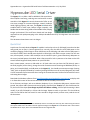
Hypnocube LED Serial Driver
The HypnoLSD is a USB or UART to WS28121 LED strand driver
that simplifies interfacing, reducing costs and need for custom
controllers. Each HypnoLSD controls thousands of LEDs at real
time rates, enough for commercial designs, artwork, hobbyist
needs, lighting projects, and more. The HypnoLSD board takes
standard USB or UART input, buffers images internally, and
handles the sensitive timing needs of the WS2812 LEDs, keeping
images synchronized. The small factor board and low design
requirements aid rapid prototyping at the hobbyist breadboard level up to integration into commercial
designs.
This document shows how to use it in designs.
Quick Start
A quick test of a newly obtained HypnoLSD module is to hook up a short (1-200 length) strand to the data
and ground pins on port 1 (connect ground first, correctly, then the data line next). Add power to the
module by plugging a USB charger or other USB source to the USB plug, and make sure the USB jumper is
set USB, not UART, which should cause the built in LED to light, then blink once per second. For the next
test, remove power, connect a LED strand (be sure to connect to port 1, ground then data), add power to
the strand, and add power the module. Wait a few seconds for built in patterns to be drawn on the LED
strand. Default length will draw patterns on up to 250 LEDs.
Next, remove power, connect a USB cable to a PC (and make sure you have the FTDI drivers) open a
terminal program (such as Putty), change the serial connection terminal settings to 9600 baud, 8 bits, no
parity, and 1 stop bit (8N1), and add power to the HypnoLSD. You should see a startup message. Entering
“help” (with no quotes) followed by a newline (pressing ENTER on most PC terminal programs) will show
a list of commands. Experiment with them. Letting the command terminal sit idle a few seconds will return
to drawing demo images.
Download the Windows software from http://hypnocube.com/product/led_serial_driver/ and play with
it. It allows GUI control of the various commands as well as the ability to set colors.
To run from any serial port, such as an Arduino, Raspberry Pi, etc., disable the USB jumper, connect to the
ground, the proper UART transmit and receive signals, send the bytes “draw\r\n”, wait a millisecond or
so, then send colors bytes (but change any 254 to 255 before sending, 254 has special meaning in draw
mode!), 3 per LED, followed by a 254 to end the image. Repeat as much as you want. This should draw
colors on the LEDs on the first strand. For more strands or longer strands, or faster rates, read the rest of
this document.
1
The HypnoLSD also supports the newer WS2812B, which is essentially the same chip, but under testing we noticed
some power differences. We added a second regulated voltage to the HypnoLSD to handle both well. It also handles
the WS2811 driver chips, which is the WS2812 without the integrated LEDs.
1
Hypnocube.com – Hypnocube LED Serial Driver Final Documentation v1.1, July 2014
Overview
The HypnoLSD module has several features to enable large scale projects. Various settings such as baud
rate, specialized timing controls, image size, and a user ID that can be programmatically queried can be
stored in on-chip FLASH to allow programs to distinguish different physical modules. There is a jumper
that can be installed to reset the FLASH settings to defaults in case of error. A diagnostic LED flickers to
denote behavior, which can also be disabled programmatically.
The module has a micro USB connection which uses a FTDI USB to UART bridge, so the device should show
up as a COM port on a computer when connecting to the USB port. If not, you need to find drivers from
the FTDI website for your PC. If you want to connect with a UART directly (from smaller or embedded
chips), set the USB/UART jumper on the module to disable the USB, and connect to the RX, TX, and GND
pins accordingly. The UART supports higher baud rates, which may be needed for larger high frame rate
designs.
There are 16 ports, labeled 1-16, each with a data and ground line. These connect to strands to run,
starting with strand 1, then 2, etc., allowing control of up to 16 LED strands.
Electrical Interface
There are two ways to power the HypnoLSD module: 1) USB power through the micro-B USB jack, and 2)
by the 5V pin and GND pin. LED strands should be connected to port 1, then port 2, etc., in order. This is
the order the drive code sends out signals.
Wires from the HypnoLSD module to the LEDs should be kept as short as possible to prevent signal
problems. Some report ~100 ohm resistors in series as helping, but we have not tested it. If long lengths
need to be run, making the USB cable longer is a better option.
The LED strands should be powered each 200-300 or so LEDs, since it appears that the power drop on
longer strands causes signaling issues, even with the signal reshaping the WS2812 supports. We also
noticed color drops as the strands went further without power, so you may need to test your LED setup
to determine needed power connections. Power consumption should max at 60 mA/LED site (as all white,
which is actually three LEDs at 20 mA each). When we tested, we found that each LED site (3 LEDs) used
under 60mA, and dropped off nearly linearly as the color (0-255) viewed dropped.
Programming Interface
This section lists programming commands, how to send images, and technical details for optimizing
software for high performance display.
Overview
The HypnoLSD allows controlling to 1-16 strands of LEDs, arranged however the user desires, at baud
rates from 9,600-12,000,000. The reason for choosing different numbers of strands and baud rates is to
allow fast image updates in different scenarios. The number of strands controlled is called width. The
length of the strands is called length (also called height in the module), and the resulting LEDs are treated
as a width by length image buffer of red, green, and blue bytes. Internally all strands are treated as the
same length, so it is best if your design has the same physical fixed length. If not, you must still send bytes
to the module as if the LEDs were a rectangular grid.
2
Hypnocube.com – Hypnocube LED Serial Driver Final Documentation v1.1, July 2014
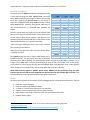
The HypnoLSD allocates 30,000 bytes of RAM as an image buffer, which is partitioned according to the
width. Due to technical details, the maximum LED strand length allowed varies as width as follows:
Strands (width)
1
2
3
4
5
6
7
8
9
10
11
12
13
14
15
16
Max length
10,000
5,000
3,125
2,500
1,875
1,250
1,250
1,250
625
625
625
625
625
625
625
625
Total pixels
10,000
10,000
9,375
10,000
9,375
7,500
8,750
10,000
5,625
6,250
6,875
7,500
8,125
8,750
9,375
10,000
Bytes used
30,000
30,000
28,125
30,000
28,125
22,500
26,250
30,000
16,875
18,750
20,625
22,500
24,375
26,250
28,125
30,000
Bytes unused
0
0
1,875
0
1,875
7,500
3,750
0
13,125
11,250
9,375
7,500
5,625
3,750
1,875
0
% used
100.00
100.00
93.75
100.00
93.75
75.00
87.50
100.00
56.25
62.50
68.75
75.00
81.25
87.50
93.75
100.00
The signaling protocol to the LEDs runs at 800khz, with 24 bits per pixel, so can light 800,000/24=33,333
pixels per second. For 30 frames per second (fps) animation, this amounts to a maximum strand length of
1111. More strands allows updating more LEDs per second.
The input baud rate limits the speed at which data can be sent into the HypnoLSD. The signaling is 8 data
bits, no parity, and one stop bit, called 8N1, and results in transmitting one byte per 10 baud. This means
a 9600 baud connection will transfer 960 bytes per second. A 1,000,000 baud connection can transfer
100,000 bytes per second. In general you should select the slowest usable baud rate that meets your
design criteria.
Example 1: highest performance is sixteen strands of length 625 (so width is 16), giving 625*16=10,000
LEDs. The HypnoLSD can refresh length 625 in 800,000/(625*24)=53 times a second. Filling 10,000 pixels
takes 30,000 bytes (one for each of red, green, and blue), and a 12,000,000 baud connection can transmit
(12,000,000/10)/(30,000)=40 frames per second. So in this case the baud rate is the limiting factor (40 <
53), but 40 frames per second is a good animation rate.
Example 2: Suppose you want to run 4,000 LEDs at 40 frames per second. This requires
4000*40*3=480,000 bytes per second, or a minimum of 4,800,000 baud input. The only supported speeds
above this are 6 and 12 Mbaud. Next, for output, the rate of 800,000/(24*40)=833 shows that at most
833 LEDs can be on a strand. 4000/833=4.8 means at least 5 strands should be used. This could be 5
strands of length 800 (cutting it close) or 8 strands of length 500. Thus parameters of 6,000,000 baud and
8 strands of length 500 would be a good design choice.
The HypnoLSD operates in two different modes: command mode and drawing mode. In command mode,
commands are sent as ASCII commands. In drawing mode, sequences of bytes are interpreted as colors
to send out to serial LEDs. Upon powering up, the HypnoLSD defaults to 9600 baud, 8N1, and command
mode, where ASCII commands are used.
3
Hypnocube.com – Hypnocube LED Serial Driver Final Documentation v1.1, July 2014
Command Mode
Commands are case-sensitive ASCII text, followed by the control characters \r\n, which are line feed (\r
= 0x0D hexadecimal = 13 decimal) and new line (\n = 0x0A hexadecimal = 10 decimal).
After each is completed, the text "OK\r\n" is returned. Any error sends a line with "ERROR: " followed
by error text, then "\r\n", then the "OK\r\n". Commands ignore input while processing, so you must
wait for the final "OK\r\n" before sending another command. Most commands execute quite quickly and
a millisecond wait should suffice if you don’t want to read the feedback messages.
In the following command table, entries of the form nnnn denote decimal integers.
Command
help
version
info
stats
sizes
get speed
set speed nnnn
get size
set size wwww hhhhh
get id
set id nnnn
get bitdelay
set bitdelay nnnn
draw
dump image nnnn
test conn nnnn rrrrr
reset stats
save settings
timings
skewtest a b c d e
Latchtest nnnn mmmm
rundemo m nnnn
demodelay mm
LED n
Result
Return basic help text.
Return version as major.minor format.
Print system info.
Show debugging stats for checking memory integrity, connection quality, etc.
Show max length for each width.
Get the current baud rate information.
Change the baud rate divisor to nnnn in 0 to 65535. See below.
Get the current buffer size width x length
Set the buffer size. wwww is width 1 to 16; hhhh is length 1 to max for this width. Use the
sizes command to find the max length for each height. Default is width 1, length 250.
Get the current user identification value 0-65535.
Set an identification value 0-65555, useful for multi-controller designs. Default 0.
Get the bit timing delay 0-65535 on each bit output. Default to 0.
Set the bit timing delay 0-65535 on each bit output.
Enter drawing mode. See the drawing section.
Dumps buffer RAM for debugging. nnnn is 1 to 30,000.
Testing mode. nnnn is size for each pass of 1 to 30,000, and rrrr is the repeat value in
1 to 231 − 1. After this, send one copy of the buffer of length nnnn to test, then rrrr
copies that are checked against the original. When done, the error counts are returned
if anything did not work.
Reset the stats counters. Useful for debugging.
Saves settings to flash memory so they do not need set each time. The settings saved
are User ID, connection rate, width, length, diagnostic LED on/off status, and demo
delay. Do not set this too often as the flash will wear out over time. The PIC
documentation gives a 20,000 cycle erase lifespan, so after about 20,000 writes the
device is out of specification. If the FLASH gets corrupted values, then default values
apply. The reset jumper allows an external reset of default.
This dumps some timing values for frame drawing code, used for debugging.
Test skew timing on strand. Used for debugging.
Test minimal latch timing. Used for debugging.
Run built in demo m (1 to max demo from info command) for nnnn milliseconds (1 to
65535). Demo 0 means do all demos. 0 milliseconds means to run the given demo until
a byte is seen in the command channel.
Set the delay before a demo runs to mm seconds (0-99). 0 means never show demos.
Defaults to 5 seconds. In command mode, if bytes are not seen for this long, then built
in demos run on any connected strands according to the current image size.
Enable/disable the onboard diagnostic LED flickering. If n=0, LED is always off. If n=1,
the LED flickers. The LED turns on at power up, flickers once per second in command
mode, and then toggles each SYNC executed in drawing mode. Defaults to 1.
4
Hypnocube.com – Hypnocube LED Serial Driver Final Documentation v1.1, July 2014
Baud Rate Calculations
The baud rate of the HypnoLSD module is changed by setting
a clock divisor through the “set speed nnnn” command
where nnnn is a divisor in the range 0 to 65535. The resulting
baud rate is given by 12,000,000/(nnnn+1). This results in
rates from 12,000,000 baud (when nnnn=0) down to 183.1
baud (nnnn=65535). However, going below 9,600 baud is
not recommended as it is untested (and probably not
useful).
Note the actual baud rate might not be the desired baud
rate, in which case you should check the error and tolerances
of your devices. Most devices support a few percent error
between desired and actual baud rates. A few common baud
rates and best divisors are in the baud rate table.
Note at the higher baud rates there is not as much selection
due to running out of divisors.
When selecting a baud rate, make sure your driving device
can handle it as well.
Desired Rate
Actual Rate
Divisor
% Error
9600
19200
38400
56000
57600
115200
250000
300000
375000
400000
480000
500000
600000
750000
800000
1000000
1200000
1500000
20000002
24000002
3000000
40000002
60000002
120000002
9600
19200
38338.66
56074.77
57692.31
115384.62
250000
300000
375000
400000
480000
500000
600000
750000
800000
1000000
1200000
1500000
2000000
2400000
3000000
4000000
6000000
12000000
1249
624
312
213
207
103
47
39
31
29
24
23
19
15
14
11
9
7
5
4
3
2
1
0
0
0
0.16
-0.13
-0.16
-0.16
0
0
0
0
0
0
0
0
0
0
0
0
0
0
0
0
0
0
The HypnoLSD with the built-in USB to UART bridge uses a
FT230X from FTDI3. The spec sheet4 describes the available
baud rates from 183 to 3Mbaud. The achievable baud rates are given by 3,000,000/(n+x) where n is an
integer in 2 to 16384 and x can be any of the 8 values {0, 0.125, 0.250, 0.375, 0.500, 0.675, 0.750, 0.875}.
A final case of n=1 and x=0 gives the top speed of 3Mbaud. When using Windows, Linux, or Mac OSX the
values should be set transparently in the OS driver when the serial port is opened.
NOTE: Note that the HypnoLSD module speeds above 3Mbaud can be reached by using the UART
interface (on the non-USB version) combined with devices based on the FT232H chip from FTDI. They
sell a breakout board that we have tested for high speed connections.
Demos
Six demos are integrated into the module to help debugging and to provide simple test patterns. They are
1.
2.
3.
4.
5.
6.
Solid color, slowly changing
Solid color blocks slide towards module.
A “plasma” of colors fades and evolves over the LEDs.
“Splats” of color are displayed, and each fades out slowly.
Eight different color blobs chase each other over the length of the strand.
Random flickering dots
2
Not reachable on the USB to UART version of the module. Needs a separate high-speed UART.
http://www.ftdichip.com/
4
http://www.ftdichip.com/Support/Documents/DataSheets/ICs/DS_FT230X.pdf
3
5
Hypnocube.com – Hypnocube LED Serial Driver Final Documentation v1.1, July 2014
Drawing Mode
In drawing mode, colors are sent as triples of colors, thought of as red, green, and blue, written RGB.
However, the order of bytes sent in is the same order the go to the LED strand, and most strands take
order green, red, blue (GRB), so the order you write them may need modified to match LED requirements.
Each byte value can be 0-255, except byte 254 is reserved as a synchronization byte, called SYNC. This
means whenever you want to send color 254, you should change that to 255. This is done in case a buggy
UART connection loses or mangles a byte, so the image can be resynchronized. Color 254 was chosen
because the visual difference between 254 and 255 is negligible.
The color order is to fill width first, then next value for the length, repeat. When all bytes for the current
frame are sent, send a SYNC byte, which marks the end of a frame and denotes to the output code that it
can begin. In fact, each SYNC byte increments an internal counter, and each frame of output that is started
by the internal code decrements this counter.
A SYNC byte also tells the writing code to start at the top of the image buffer for the next byte.
Entering two SYNC bytes in a row exits drawing mode back to command mode.
Detailed Control
There may be some uses where careful timing of the input and output streams needs synchronized for
robust images, no tearing, or to sync with other needs such as video.
Internally, the code has a RAM buffer for the image consisting of 30,000 bytes laid out in a special manner
allowing efficient code to manage it quickly. In drawing mode, this buffer is simultaneously being written
into with incoming data (from the USB or UART interfaces) and read from to get outgoing data (to the
LEDs). It is possible for reading/writing to step on each other during a frame, which can result in a “tearing”
of images. The SYNC byte (254) which marks the end of a frame also allows careful timing control to avoid
any accidental stepping on each other.
At all times the reader (for LED output) and writer (for incoming data from UART or USB) are walking
through memory, top to bottom, trying to do their jobs. When a SYNC is sent, a 32-bit SYNC counter is
incremented, the low order byte is output to the UART so you can track it, and the writer is restarted from
the top, with the first color channel (R in RGB, or G in GRB, etc.). Whenever the reader reaches the end of
whatever it is doing, it checks this counter, and if it is not greater than zero, the reader has a delay until it
checks again. Whenever the SYNC counter is greater than zero, the reader decrements the counter, and
sends (low order counter byte + 64) to the UART port. The +64 is to help track what is going on in your
code.
Note that the reader does not send these output bytes if there are already bytes being transmitted from
a previous round. If your baud rate is too slow some output bytes will be skipped.
Once these bytes are seen, the reader starts at the top, reading from the top of RAM and sending the data
to the LEDs.
Here is the important timing detail: The reader processes output at 800kbits per second (on each strand
since it’s done in parallel). After one pixel of output is sent, it is safe to write one pixel of input. If your
writer fills pixels into RAM faster than they are output by the reader, then you will catch and pass the
6
Hypnocube.com – Hypnocube LED Serial Driver Final Documentation v1.1, July 2014
reader. So if you’re finding some tearing of your images, think through this and try to make a proper delay
to sync the images. The internal code timing is rock solid, so doing some testing should demonstrate what
delays you may need to prevent the input and output from stepping on each other. In practice we have
yet to see any problems with this.
Long Strand Issues
When strands get longer, the signal shaping in the WS2812 modules begins to have problems keeping a
solid image. With the default timing, we have successfully run 2500 length strands with no problems, in a
4x2500 configuration. For longer strands, such as the 2x5000 or 1x10000 configuration, we had to add
small delays on output timing to prevent signals from “bunching up” and dropping signal. This is
accomplished by the set bitdelay command. The default bitdelay of 0 outputs equal spaced timing for
each bit, longer delays lengthen the mandatory low between bits.
The delay needed depends on the wiring, especially if there are long connectors between some LEDs. We
have found signals seems to get messed up more often where there are long wires between LEDs, where
soldering patterns change, etc. For a 10K display we created using 8 panels, each with 1250 LEDs in series,
we were able to drive all 10K as one strand using a bit delay between 6 to 99. Larger values resulted in
garbage. Arranged as two 5K strands, we were able to use a bit delay of 2. In practice use the lowest value
that allows your display to work reliably.
For details see our article “Design and Implementation of Serial LED Gadgets.”5
Gallery
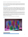
Figure 1 - 10,000 LED curved panel
5
http://hypnocube.com/2013/12/design-and-implementation-of-serial-led-gadgets/
7
Hypnocube.com – Hypnocube LED Serial Driver Final Documentation v1.1, July 2014
Figure 1 shows 10,000 LEDs arranged in eight curved panel pieces we made to test all of the
HypnoLSD features. We set it up to test all combinations of strand counts and lengths to make
sure the device can handle many configurations. A video of it running graphics demos we created
is available at https://www.youtube.com/watch?v=SzpcPrnh9LY.
Other projects we have made for testing include Christmas lights, 60x16 panel, a conical hat, and
numerous other small devices. If you build interesting projects using this device send us a
description and images if you want, and we will try to add them to our website and future versions
of this document.
Happy hacking
8
Hypnocube.com – Hypnocube LED Serial Driver Final Documentation v1.1, July 2014
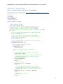
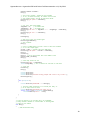
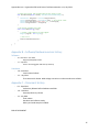
Appendix A - Sample Code
Here are a few code samples to show how to use the HypnoLSD.
Sample software can be obtained from http://hypnocube.com/product/led_serial_driver/.
C# Sample
using
using
using
using
System;
System.IO.Ports;
System.Text;
System.Threading;
namespace Hypnocube.LSD.Sample1
{
// TODO - explain C# for newbs
// Don't need to delete like C++
// We tried to remove most C#-isms from the below to make the code
// easier to port to C or JAVA. We removed normal XML commenting,
// implicit variables, the default static class for Main, TODO
// This C# should work in Linux under mono, Windows, and Mac under mono (TODO)
class Program
{
// This is the string used to mark end of a command to the device
const string CommandEnd = "\r\n";
// This is the value of a sync byte used for sending images.
// Images cannot have this byte in them - we recommend replacing
// such bytes any with value 255.
const byte SyncByte = 254;
// This is a sample program, showing how to set up the device and
// perform various options
void SampleProgram(string[] args)
{
// get the name of the port we will use
string portName = "COM8";
if (args.Length == 1)
portName = args[0];
// wrap this in try/catch blocks to catch errors
try
{
// open the serial port at the default rate of 9600
OpenPort(9600, portName);
// get attention of the device by sending a few empty lines
// Also helps in case the built in demos were running.
WriteString(CommandEnd);
WriteString(CommandEnd);
// wait a moment.
Delay();
// Ask for the version
WriteString("version" + CommandEnd);
Delay();
// to draw images quickly, we will use a higher baud
// rate of 115200 (most serial device should support it)
// This requires a "divider" of 103. (See manual for values).
int divider = 103;
WriteString("set speed " + divider + CommandEnd);
Delay();
// must close and re-open port
ClosePort();
Delay();
9
Hypnocube.com – Hypnocube LED Serial Driver Final Documentation v1.1, July 2014
OpenPort(115200, portName);
Delay();
// see if port changed - should see this message
// if not, increase the delay. Or comment out the code
// that changes speed, and see if everything works.
WriteString("get speed" + CommandEnd);
Delay();
// now, let's draw some images!
imageWidth = 4;
// 4 strands wide
imageHeight = 30; // 30 pixels tall
WriteString("set size " + imageWidth + " " + imageHeight + CommandEnd);
Delay();
WriteString("get size " + CommandEnd);
Delay();
DrawImages();
// make sure to get the console again
WriteString(CommandEnd);
// wait a moment.
Delay();
// return to 9600 speed so we don't have to reset the hardware
// to run this sample again
divider = 1249; // divider value for 9600 baud
WriteString("set speed " + divider + CommandEnd);
Delay();
ClosePort();
Delay(); // we put more delays here since 9600 is slow
OpenPort(9600, portName);
Delay();
// check help screen for fun
WriteString("help" + CommandEnd);
Thread.Sleep(5000); // wait 5 seconds for all data to come back
// close port
ClosePort();
Delay();
Console.WriteLine();
Console.WriteLine();
Console.WriteLine("Finished running sample code. Press a key to exit.");
WaitForKeypress();
}
catch (Exception e)
{
Console.WriteLine("EXCEPTION: " + e.Message);
// The most common exception is an invalid port name, so
// we'll output them all here.
Console.WriteLine("Available port names are:");
foreach (string name in SerialPort.GetPortNames())
Console.WriteLine("Port: " + name);
}
}
// since the device is not terribly fast, we recommmend
// delays between commands in console mode. In drawing mode
// these are not needed.
void Delay()
{
// 200 millisecond delay
10
Hypnocube.com – Hypnocube LED Serial Driver Final Documentation v1.1, July 2014
Thread.Sleep(200);
}
// here is our serial port. Various languages and OSes
// have different ways of dealing with them.
SerialPort port;
// We will open a port given the name and desired baud rate.
// The device defaults to 9600 baud, 8N1, no handshake, so we
// set that in here. Since we also want faster signaling than
// 9600, we allow the baudrate as a parameter.
void OpenPort(int speed, string portName)
{
// if we already have a port, Close it first
if (port != null)
ClosePort();
// create a new port with desired parameters
port = new SerialPort
{
BaudRate = speed,
DataBits = 8,
Parity = Parity.None,
StopBits = StopBits.One,
Handshake = Handshake.None,
// C#/.NET needs to change the default encoding on a serial port
// to get bytes back and forth without interference.
// This encoding will do it.
Encoding = Encoding.GetEncoding("Windows-1252")
};
// we attach some listeners (think function pointer)
// to catch errors and returned bytes
port.DataReceived += DataReceived;
port.ErrorReceived += ErrorReceived;
// set the port name, such as "COM2" in windows
port.PortName = portName;
// And try to open it.
// This throws an exception if it cannot be opened.
port.Open();
}
// close the serial port
void ClosePort()
{
if (port != null)
{
// remove listeners
port.DataReceived -= DataReceived;
port.ErrorReceived -= ErrorReceived;
if (port.IsOpen)
port.Close();
}
// set to null for safety
port = null;
}
// we send all string commands to the port through here,
// because strings in C# are unicode, and we must send
// ASCII strings
void WriteString(string format, params object[] args)
{
byte [] bytes = Encoding.ASCII.GetBytes(String.Format(format, args));
WriteBytes(bytes);
}
// Write an array of bytes to the port.
11
Hypnocube.com – Hypnocube LED Serial Driver Final Documentation v1.1, July 2014
void WriteBytes(byte[] data)
{
if (port.IsOpen)
port.Write(data, 0, data.Length);
}
// the image width (# of strands 1-16)
int imageWidth;
// the image height (length of a strand)
int imageHeight;
// the image will be stored here as it is constructed, then
// once set, will be sent at once
// The image is stored width first, then height. Each pixel is
// 3 bytes of red, green, blue color (RGB).
byte [] buffer;
// given a coordinate i,j and color red,green,blue,
// set a pixel in the buffer
void SetPixel(int i, int j, int red, int green, int blue)
{
// pixels go in buffer as:
int index = (i + j*imageWidth)*3;
// check bounds
if (index < 0 || buffer.Length <= index)
return; // out of bounds. Ignore
// set the red, green, and blue components
buffer[index++] = (byte)red;
buffer[index++] = (byte)green;
buffer[index]
= (byte)blue;
}
// Fill image with one color. Useful for clears
void Fill(int red, int green, int blue)
{
for (int i =0 ; i < imageWidth; ++i)
for (int j = 0; j < imageHeight; ++j)
SetPixel(i, j, red, green, blue);
}
// this is a very important function. It copies the buffer
// to the device, but first it ensures no SYNC bytes are in the
// image. It replaces any SYNC bytes in the buffer with 255, then
// appends a SYNC byte to notify the gadget that the image is done.
// Finally, it transfers the data over the serial port to the gadget.
// NOTE: the gadget must be in drawing mode for this to work.
void TransferImage()
{
// remember - we cannot send a sync byte in the image, so
// we'll remap in place
for (int i = 0; i < buffer.Length; ++i)
if (buffer[i] == SyncByte)
buffer[i] = 255;
buffer[buffer.Length - 1] = SyncByte; // image ends with a sync byte
// draw it
WriteBytes(buffer);
}
// we track drawing mode so we can print returned bytes differently
bool drawing = false;
void DrawImages()
{
// each pixel needs three bytes for RGB
// we add one byte to append a SYNC byte
buffer = new byte[imageWidth * imageHeight * 3 + 1];
// enter draw mode
drawing = true;
12
Hypnocube.com – Hypnocube LED Serial Driver Final Documentation v1.1, July 2014
WriteString("draw" + CommandEnd);
Delay();
Console.WriteLine("Press a key for red");
WaitForKeypress();
// Fill buffer with red
Fill(255,0,0);
// send the image to the device
TransferImage();
// green
Console.WriteLine("Press a key for green");
WaitForKeypress();
Fill(0, 255, 0);
TransferImage();
// blue
Console.WriteLine("Press a key for blue");
WaitForKeypress();
Fill(0, 0, 255);
TransferImage();
Console.WriteLine("Press a key for a plasma");
WaitForKeypress();
// do a demo of something more complex
ShowPlasma();
// clear image before exiting
Fill(0,0,0);
TransferImage();
// exit drawing - spec calls for 2 sync bytes, but we send three to make sure :)
byte [] syncs = new byte[] {SyncByte, SyncByte, SyncByte};
WriteBytes(syncs);
Delay();
drawing = false;
}
// show a plasma colored demo until a key is pressed
void ShowPlasma()
{
Console.WriteLine("Press a key to exit plasma");
int frame = 0;
while (Console.KeyAvailable == false)
{
// fill the image
for (int i = 0; i < imageWidth; ++i)
for (int j = 0; j < imageHeight; ++j)
{
// compute some colors based on position and frame
double angle = frame/10.0;
double c = Math.Sin(
angle +
Math.Sin(i/10.0+angle/10.0) +
12*Math.Cos(j/27.0+i/30.0)
);
// c is in -1 to 1, so map to 0-255 for red
int red = (int)(((c + 1) / 2.0 * 255.0));
// do similarly for green and blue
c = Math.Sin(
1.1*angle +
1.2*Math.Sin(i / 13.0 + angle / 12.0) +
7 * Math.Cos(j / 22.0 + i / 27.0)
13
Hypnocube.com – Hypnocube LED Serial Driver Final Documentation v1.1, July 2014
);
int green = (int)(((c + 1) / 2.0 * 255.0));
c = Math.Sin(
0.9*angle +
1.7*Math.Sin(i / 9.0 + angle / 13.0) +
9 * Math.Cos(j / 31.0 + i / 28.0)
);
int blue = (int)(((c + 1) / 2.0 * 255.0));
SetPixel(i,j,red,green,blue);
}
// send the image to the device
TransferImage();
// Wait a moment to avoid moving too fast :)
//Thread.Sleep(100);
// next frame - causes change over time
++frame;
}
// read any keypresses before returning
while (Console.KeyAvailable == true)
Console.ReadKey(true);
}
// wait for a key to be pressed.
// this differs in many languages/OSes, but
// the same C# code should work.
void WaitForKeypress()
{
// wait for keypress
while (Console.KeyAvailable == false)
Delay();
// absorb keypresses
while (Console.KeyAvailable == true)
Console.ReadKey(true);
}
// when the serial port sees data, it comes to here, and is output
// to the console. The color depends on if we're in drawing mode or
// not.
private void DataReceived(object sender, SerialDataReceivedEventArgs e)
{
SerialPort senderPort = (SerialPort) sender;
int bytesToRead = senderPort.BytesToRead;
byte [] data = new byte[bytesToRead];
senderPort.Read(data, 0, bytesToRead);
ConsoleColor foregroundColor = Console.ForegroundColor;
if (drawing == true)
Console.ForegroundColor = ConsoleColor.Cyan;
else
Console.ForegroundColor = ConsoleColor.Yellow;
foreach (byte b in data)
{
// if the byte is printable ASCII, show it as such, else
// show the byte value in brackets []
if ((32 <= b && b < 128) || b == 8 || b == 10 || b == 13)
Console.Write((char) b);
else
Console.Write("[" + (int)b + "]");
}
// restore the foreground color
Console.ForegroundColor = foregroundColor;
}
14
Hypnocube.com – Hypnocube LED Serial Driver Final Documentation v1.1, July 2014
// serial port errors come through here and are output in red.
void ErrorReceived(object sender, SerialErrorReceivedEventArgs e)
{
ConsoleColor foreground = Console.ForegroundColor;
Console.ForegroundColor = ConsoleColor.Red; // set an error color
Console.Error.WriteLine("Port error {0}", e.EventType);
Console.ForegroundColor = foreground;
}
// C# console programs start here
static void Main(string[] args)
{
// create a new instance of this program
Program program = new Program();
// and run it
program.SampleProgram(args);
}
}
}
Appendix B – Software/hardware version history
Software
-
1.0 - Nov 2013 – June 2014
Original (unshipped) version.
1.1 – July 2014
Fixes a rare timing glitch that locks up the chip.
Hardware
-
1.0 – Nov 2013
Initial internal release
1.1 - July 2014
First commercial release. Adds voltage correction to make strands more reliable.
Appendix C – Document History
-
0.1 - Sept 2013
Preliminary Release before hardware available
1.0 - Feb 2014
Second preliminary release.
1.1 - July 2014
Final release.
Hardware and software ready.
Gallery and code samples included.
END OF DOCUMENT
15