1
PowerDNA API Reference Manual, Release 4.0
PowerDNA API Reference Manual
Release 4.1
June 1st, 2010 Edition
© Copyright 2003-2010 United Electronic Industries, Inc. All rights reserved
No part of this publication may be reproduced, stored in a retrieval system, or transmitted, in any form by any means, electronic,
mechanical, by photocopying, recording, or otherwise without prior written permission.
PowerDNA API Reference Manual, Release 4.0
1
2
Introduction.......................................................................................... 1
Five ways to communicate with IOM .................................................. 1
2.1
2.1.1
2.1.2
2.1.3
2.1.4
2.2
2.2.1
2.2.2
2.2.3
2.2.4
2.2.5
2.2.6
2.2.7
2.2.8
2.2.9
2.2.10
2.2.11
2.2.12
2.2.13
2.2.14
2.2.15
2.2.16
2.2.17
2.2.18
2.2.19
2.2.20
2.2.21
2.2.22
2.2.23
2.2.24
2.2.25
2.2.26
2.2.27
2.2.28
2.2.29
2.2.30
2.2.31
2.2.32
2.2.33
2.2.34
2.2.35
2.2.36
2.2.37
2.2.38
2.2.39
Pre-defined Types and Error Codes ....................................................................... 2
Pre-defined Types ...................................................................................................... 2
Devices and subsystems ........................................................................................... 2
DaqBIOS Packet Structures....................................................................................... 3
Error Codes................................................................................................................ 3
Auxiliary Functions .................................................................................................. 4
DqTranslateError ....................................................................................................... 5
DqInitDAQLib ............................................................................................................. 5
DqCleanUpDAQLib .................................................................................................... 5
DqGetLibVersion........................................................................................................ 6
DqOpenIOM ............................................................................................................... 6
DqCloseIOM .............................................................................................................. 7
DqGetDevnBySlot ...................................................................................................... 7
DqGetDevnBySerial ................................................................................................... 8
DqSetPacketSize ....................................................................................................... 8
DqSetTimeout ............................................................................................................ 9
DqReadSrec .............................................................................................................. 9
DqGetLastStatus ...................................................................................................... 10
DqReadAIChannel ................................................................................................... 11
DqWriteAOChannel ................................................................................................. 11
DqCmdEcho............................................................................................................. 12
DqCmdReset ........................................................................................................... 12
DqCmdHwReset ...................................................................................................... 13
DqCmdWriteVal ....................................................................................................... 14
DqCmdReadVal ....................................................................................................... 14
DqCmdWriteMultipleValues ..................................................................................... 15
DqCmdReadMultipleValues ..................................................................................... 15
DqCmdSetCfg .......................................................................................................... 16
DqCmdReadStatus .................................................................................................. 18
DqCmdWriteChannel ............................................................................................... 20
DqCmdReadChannel ............................................................................................... 21
DqCmdSetClock ...................................................................................................... 22
DqCmdSwTrigger .................................................................................................... 23
DqCmdSetChannelList ............................................................................................ 23
DqCmdSetTransferList ............................................................................................ 25
DqCmdWriteAll ........................................................................................................ 25
DqCmdReadAll ........................................................................................................ 26
DqCmdWriteReadAll ................................................................................................ 27
DqCmdWriteFIFO .................................................................................................... 28
DqCmdReadFIFO .................................................................................................... 28
DqCmdWriteReadFIFO ............................................................................................ 29
DqCmdWriteToFlashBuffer ...................................................................................... 30
DqCmdUpdateFlashBuffer ....................................................................................... 31
DqCmdSetCommParameters .................................................................................. 32
DqCmdSetName ...................................................................................................... 33
-i-
PowerDNA API Reference Manual, Release 4.0
2.2.40
2.2.41
2.2.42
2.2.43
2.2.44
2.2.45
2.2.46
2.2.47
2.2.48
2.2.49
2.2.50
2.2.51
2.2.52
2.2.53
DqCmdGetName ..................................................................................................... 33
DqCmdSetParameters ............................................................................................. 34
DqCmdGetParameters ............................................................................................ 35
DqCmdSaveParameters .......................................................................................... 37
DqCmdSetCalibration .............................................................................................. 37
DqCmdSetMode ...................................................................................................... 38
DqCmdSetReplyMaxSize ........................................................................................ 40
DqCmdSetPassword ................................................................................................ 40
DqCmdGetCRC ....................................................................................................... 41
DqCmdIoctl .............................................................................................................. 42
DqCmdGetCapabilities ............................................................................................ 43
DqCmdInitIOM ......................................................................................................... 44
DqCmdSetTrigger .................................................................................................... 45
DqCmdSetLock ........................................................................................................ 46
3
High-Level API ................................................................................... 48
3.1
3.1.1
3.1.2
3.1.3
3.1.4
3.1.5
3.1.6
3.1.7
3.1.8
3.2
3.2.1
3.2.2
3.2.3
3.2.4
3.2.5
3.2.6
3.2.7
3.2.8
3.3
3.3.1
3.3.2
3.3.3
3.3.4
3.3.5
3.4
3.4.1
3.4.2
3.4.3
3.4.4
3.4.5
3.4.6
3.4.7
3.4.8
3.4.9
Common ACB, DMap, and Msg functions ........................................................... 48
DqAcbIsSupported ................................................................................................... 48
DqDmapIsSupported ............................................................................................... 48
DqVmapIsSupported ................................................................................................ 49
DqMsgIsSupported .................................................................................................. 49
DqStartDQEngine .................................................................................................... 50
DqStopDQEngine .................................................................................................... 51
DqParamDQEngine ................................................................................................. 51
DqAdvReadCalData................................................................................................. 52
Advanced Circular Buffer (ACB) Functions......................................................... 53
DqAcbCreate ........................................................................................................... 53
DqAcbDestroy .......................................................................................................... 53
DqAcbInitOps ........................................................................................................... 54
DqAcbGetScansCopy .............................................................................................. 58
DqAcbGetScans ...................................................................................................... 59
DqAcbPutScansCopy .............................................................................................. 60
DqAcbPutScans ....................................................................................................... 61
DqAcbSetBurstMode ............................................................................................... 62
Direct Data Mapping (DMap) Functions ............................................................... 62
DqDmapCreate ........................................................................................................ 63
DqDmapInitOps ....................................................................................................... 63
DqDmapDestroy ...................................................................................................... 64
DqDmapAddEntry .................................................................................................... 64
DqDmapAddMultipeEntries ...................................................................................... 65
Real-time Data Mapping (Dmap) Functions ......................................................... 66
DqRtDmapInit .......................................................................................................... 67
DqRtDmapAddChannel ........................................................................................... 68
DqRtDmapGetInputMap .......................................................................................... 68
DqRtDmapGetInputMapSize.................................................................................... 68
DqRtDmapGetOutputMap ........................................................................................ 69
DqRtDmapGetOutputMapSize ................................................................................. 69
DqRtDmapReadScaledData .................................................................................... 70
DqRtDmapReadRawData16 .................................................................................... 70
DqRtDmapReadRawData32 .................................................................................... 71
- ii -
PowerDNA API Reference Manual, Release 4.0
3.4.10 DqRtDmapWriteScaledData .................................................................................... 71
3.4.11 DqRtDmapWriteRawData16 .................................................................................... 72
3.4.12 DqRtDmapWriteRawData32 .................................................................................... 72
3.4.13 DqRtDmapStart ........................................................................................................ 73
3.4.14 DqRtDmapStop ........................................................................................................ 73
3.4.15 DqRtDmapRefresh ................................................................................................... 74
3.4.16 DqRtDmapRefreshOutputs ...................................................................................... 74
3.4.17 DqRtDmapRefreshInputs ......................................................................................... 75
3.4.18 DqRtDmapClose ...................................................................................................... 75
3.5
Real time Variable-size Data Mapping (VMap) Functions ................................... 75
3.5.1
DqRtVmapInit........................................................................................................... 77
3.5.2
DqRtVmapAddChannel ............................................................................................ 78
3.5.3
DqRtVmapGetInputMap ........................................................................................... 78
3.5.4
DqRtVmapGetOutputMap ........................................................................................ 79
3.5.5
DqRtVmapAddOutputData ....................................................................................... 79
3.5.6
DqRtVmapGetOutputDataSz ................................................................................... 80
3.5.7
DqRtVmapRqInputDataSz ....................................................................................... 80
3.5.8
DqRtVmapGetInputData .......................................................................................... 81
3.5.9
DqRtVmapStart ........................................................................................................ 81
3.5.10 DqRtVmapStop ........................................................................................................ 81
3.5.11 DqRtVmapRefresh ................................................................................................... 82
3.5.12 DqRtVmapRefreshOutputs ...................................................................................... 82
3.5.13 DqRtVmapRefreshInputs ......................................................................................... 83
3.5.14 DqRtVmapClose ...................................................................................................... 83
3.6
Real time Variable-size Data Variable-channels Mapping (VMap+) Functions . 83
3.6.1
DqRtVmapAddOutputChannelData ......................................................................... 84
3.6.2
DqRtVmapRqInputChannelDataSz .......................................................................... 85
3.7
Simplified VMap and VMap+ Functions ............................................................... 85
3.7.1
DqRtVmapInitOutputPacket ..................................................................................... 87
3.7.2
DqRtVmapWriteOutput ............................................................................................ 87
3.7.3
DqRtVmapPlusWriteOutput ..................................................................................... 88
3.7.4
DqRtVmapRequestInput .......................................................................................... 88
3.7.5
DqRtVmapPlusRequestInput ................................................................................... 89
3.7.6
DqRtVmapReadInput ............................................................................................... 90
3.7.7
DqRtVmapInputFifoAvailable ................................................................................... 90
3.7.8
DqRtVmapOutputFifoAvailable ................................................................................ 91
3.8
Messaging (Msg) Functions .................................................................................. 93
3.8.1
DqMsgCreate ........................................................................................................... 93
3.8.2
DqMsgInitOps .......................................................................................................... 93
3.8.3
DqMsgDestroy ......................................................................................................... 94
3.8.4
DqMsgRecvMessage ............................................................................................... 94
3.8.5
DqMsgSendMessage ............................................................................................... 95
3.8.6
DqMsgCount ............................................................................................................ 96
3.9
Mapped Messaging Mode (M3) Functions (No longer supported in 3.8.0+
releases)................................................................................................................................ 96
3.9.1
DqMmCreate............................................................................................................ 96
3.9.2
DqMmInitOps ........................................................................................................... 97
3.9.3
DqMmDestroy .......................................................................................................... 97
3.9.4
DqMmSetEntry......................................................................................................... 98
- iii -
PowerDNA API Reference Manual, Release 4.0
3.9.5
3.9.6
3.9.7
3.9.8
3.10
3.10.1
3.10.2
3.10.3
3.10.4
3.11
3.11.1
3.11.2
3.11.3
3.11.4
3.11.5
3.11.6
3.11.7
3.11.8
3.11.9
3.11.10
3.11.11
3.11.12
3.11.13
3.11.14
DqMmSetLayerConfig.............................................................................................. 99
DqMmRecvMessage ................................................................................................ 99
DqMmSendMessage ............................................................................................. 100
DqMmCount ........................................................................................................... 101
ACB and DMap Control and Event Functions ................................................... 101
DqeEnable ............................................................................................................. 101
DqeSetEvent .......................................................................................................... 102
DqeGetEvent ......................................................................................................... 104
DqeWaitForEvent ................................................................................................... 104
Asynchronous Event Functions ......................................................................... 105
DqRtAsyncOpenIOM ............................................................................................. 107
DqRtAsyncCloseIOM ............................................................................................. 107
DqRtAsyncClearEvents ......................................................................................... 108
DqRtAsyncEnableEvents ....................................................................................... 108
DqRtAsyncEnableEvents ....................................................................................... 109
DqRtAsyncAssignEvent ......................................................................................... 109
DqRtAsyncGetEventPacket ................................................................................... 110
DqRtAsyncProcessEvent ....................................................................................... 111
DqRtAsyncWaitForEvent ....................................................................................... 111
DqRtAsyncReceive ............................................................................................ 112
DqRtAsyncSend ................................................................................................. 114
DqRtAsyncVmapRefreshInputs and DqRtAsyncDmapRefreshInputs ................ 115
DqRtAsyncVmapRefreshOutputs and DqRtAsyncDmapRefreshOutputs ........... 116
DqRtAsyncSendResponse ................................................................................. 116
4
Layer specific functions .................................................................. 117
4.1
4.1.1
4.2
4.2.1
4.2.2
4.2.3
4.3
4.3.1
4.3.2
4.4
4.4.1
4.4.2
4.4.3
4.4.4
4.4.5
4.4.6
4.4.7
4.5
4.5.1
4.5.2
4.5.3
4.5.4
4.5.5
4.6
DNA-AI-201/202 layers ......................................................................................... 117
DqAdv201Read...................................................................................................... 117
DNA-AI-205 layer .................................................................................................. 118
DqAdv205Read...................................................................................................... 118
DqAdv205LoadCoeff .............................................................................................. 119
DqAdv205SetFilterMode ........................................................................................ 120
DNA-AI-207 layer .................................................................................................. 121
DqAdv207Read...................................................................................................... 121
DqAdv207ReadChannel ........................................................................................ 122
DNA-AI-208 layer .................................................................................................. 123
DqAdv208Read...................................................................................................... 123
DqAdv208SetControl ............................................................................................. 124
DqAdv208SetExcVoltage ....................................................................................... 125
DqAdv208ReadChannel ........................................................................................ 126
DqAdv208MeasureParams .................................................................................... 127
DqAdv208ReadAutogain ....................................................................................... 129
DqAdv208ShuntCal ............................................................................................... 129
DNA-AI-211 layer .................................................................................................. 130
DqAdv211Read...................................................................................................... 130
DqAdv211SetCfgChannel ...................................................................................... 131
DqAdv211SetCfgLayer .......................................................................................... 135
DqAdv211SetFIR ................................................................................................... 137
DqAdv211SetPll ..................................................................................................... 139
DNA-AI-217 layer .................................................................................................. 140
- iv -
PowerDNA API Reference Manual, Release 4.0
4.6.1
4.6.2
4.6.3
4.6.4
4.6.5
4.7
4.7.1
4.7.2
4.7.3
4.7.4
4.7.5
4.7.6
4.7.7
4.8
4.8.1
4.8.2
4.9
4.9.1
4.9.2
4.9.3
4.9.4
4.9.5
4.9.6
4.9.7
4.9.8
4.9.9
4.9.10
4.9.11
4.9.12
4.9.13
4.9.14
4.9.15
4.10
4.10.1
4.10.2
4.10.3
4.10.4
4.10.5
4.10.6
4.10.7
4.10.8
4.10.9
4.10.10
4.10.11
4.10.12
4.10.13
4.11
4.11.1
4.11.2
DqAdv217Read...................................................................................................... 140
DqAdv217GetPgaStatus ........................................................................................ 140
DqAdv217SetCjcAvg ............................................................................................. 141
DqAdv217SetFIR ................................................................................................... 143
DqAdv217SetPll ..................................................................................................... 145
DNA-AI-224 layer .................................................................................................. 146
DqAdv224Read...................................................................................................... 146
DqAdv224SetAveraging ......................................................................................... 148
DqAdv224SetBridgeCompletion ............................................................................ 149
DqAdv224SetExcitation ......................................................................................... 150
DqAdv224SetFIR ................................................................................................... 150
DqAdv224SetNullLevel .......................................................................................... 152
DqAdv224SetShunt ............................................................................................... 153
DNA-AI-225 layer .................................................................................................. 154
DqAdv225Read...................................................................................................... 154
DqAdv225SetRate ................................................................................................. 155
DNA-AI-254 layer .................................................................................................. 156
DqAdv254SetMode ................................................................................................ 158
DqAdv254SetExt .................................................................................................... 159
DqAdv254SetExcitation ......................................................................................... 160
DqAdv254GetWFMeasurements ........................................................................... 161
DqAdv254MeasureWF........................................................................................... 164
DqAdv254Enable ................................................................................................... 164
DqAdv254GetExcitation ......................................................................................... 165
DqAdv254Read...................................................................................................... 166
DqAdv254ReadVrms ............................................................................................. 167
DqAdv254Write ...................................................................................................... 168
DqAdv254ConvertSim ........................................................................................... 169
DqAdv254WriteBin................................................................................................. 170
DqAdv254SetWForm ............................................................................................. 171
DqAdv254ReadDIn ................................................................................................ 172
DqAdv254WriteDOut ............................................................................................. 173
DNA-AI-255 layer .................................................................................................. 173
DqAdv255SetMode ................................................................................................ 176
DqAdv255SetExt .................................................................................................... 177
DqAdv255SetExcitation ......................................................................................... 178
DqAdv255GetWFMeasurements ........................................................................... 179
DqAdv255MeasureWF........................................................................................... 181
DqAdv255Enable ................................................................................................... 181
DqAdv255GetExcitation ......................................................................................... 182
DqAdv255Read...................................................................................................... 183
DqAdv255Write ...................................................................................................... 184
DqAdv255ConvertSim ........................................................................................ 186
DqAdv255WriteBin ............................................................................................. 187
DqAdv255ReadDIn ............................................................................................ 188
DqAdv255WriteDOut .......................................................................................... 189
DNA-AO-302/308/332/333 layers ......................................................................... 190
DqAdv3xxWrite ...................................................................................................... 190
DqAdv333ReadADC .............................................................................................. 191
-v-
PowerDNA API Reference Manual, Release 4.0
4.12
4.12.1
4.12.2
4.12.3
4.13
4.13.1
4.13.2
4.13.3
4.14
4.14.1
4.14.2
4.14.3
4.15
4.15.1
4.16
4.16.1
4.16.2
4.16.3
4.17
4.17.1
4.17.2
4.17.3
4.17.4
4.18
4.18.1
4.18.2
4.18.3
4.18.4
4.18.5
4.19
4.19.1
4.19.2
4.19.3
4.19.4
4.20
4.20.1
4.20.2
4.21
4.21.1
4.21.2
4.21.3
4.21.4
4.21.5
4.21.6
4.21.7
4.21.8
4.21.9
4.21.10
4.21.11
DNA-AO-358 layer ................................................................................................ 192
DqAdv358ExCalAccess ......................................................................................... 192
DqAdv358Write ...................................................................................................... 193
DqAdv358ReadADC .............................................................................................. 194
DNA-DIO-401/402/404/405/406 layers ................................................................. 195
DqAdv40xWrite ...................................................................................................... 195
DqAdv40xRead ...................................................................................................... 196
DqAdv40xSetHyst .................................................................................................. 197
DNA-DIO-403 layer ............................................................................................... 197
DqAdv403SetIo ...................................................................................................... 197
DqAdv403Write ...................................................................................................... 198
DqAdv403Read...................................................................................................... 198
DNA-DIO-404/406 layers ...................................................................................... 199
DqAdv404SetHyst .................................................................................................. 199
DNA-DIO-416 layer ............................................................................................... 200
DqAdv416GetAll .................................................................................................... 200
DqAdv416SetAll ..................................................................................................... 202
DqAdv416SetLimit ................................................................................................. 204
DNA-DIO-432/433 layers ...................................................................................... 205
DqAdv432GetAll .................................................................................................... 205
DqAdv432SetAll ..................................................................................................... 207
DqAdv432SetLimit ................................................................................................. 208
DqAdv432SetPWM ................................................................................................ 209
DNA-DIO-448 layer ............................................................................................... 211
DqAdv448Read...................................................................................................... 211
DqAdv448ReadAdc ............................................................................................... 211
DqAdv448SetAll ..................................................................................................... 212
DqAdv448SetLevels .............................................................................................. 213
DqAdv448SetDebouncer ....................................................................................... 214
DNA-DIO-462 layer ............................................................................................... 215
DqAdv462ReadAdc ............................................................................................... 215
DqAdv462GetAll .................................................................................................... 216
DqAdv462SetAll ..................................................................................................... 217
DqAdv462SetLimit ................................................................................................. 218
Serial-500 layer (ColdFire IOM only) ................................................................... 219
DqAdv500SetConfig .............................................................................................. 219
DqAdv500SetTxCondition ...................................................................................... 220
DNA-SL-501 and DNA-SL-508 layers .................................................................. 221
DqAdv501BaseClock ............................................................................................. 221
DqAdv501ChangeChannelCfg ............................................................................... 222
DqAdv501ChangeChannelParity ........................................................................... 222
DqAdv501SetChannelCfg ...................................................................................... 223
DqAdv501SetBaud ................................................................................................ 224
DqAdv501SetTimeout ............................................................................................ 225
DqAdv501SetTermString ....................................................................................... 225
DqAdv501SetWatermark ....................................................................................... 226
DqAdv501SetTermLength...................................................................................... 227
DqAdv501SetCharDelay .................................................................................... 227
DqAdv501SetFrameDelay .................................................................................. 228
- vi -
PowerDNA API Reference Manual, Release 4.0
4.21.12
4.21.13
4.21.14
4.21.15
4.21.16
4.21.17
4.21.18
4.21.19
4.22
4.22.1
4.22.2
4.22.3
4.22.4
4.22.5
4.22.6
4.22.7
4.22.8
4.22.9
4.23
4.23.1
4.24
4.24.1
4.24.2
4.24.3
4.24.4
4.24.5
4.24.6
4.24.7
4.24.8
4.24.9
4.24.10
4.24.11
4.24.12
4.24.13
4.24.14
4.24.15
4.24.16
4.24.17
4.24.18
4.24.19
4.24.20
4.25
4.25.1
4.25.2
4.25.3
4.25.4
4.25.5
4.25.6
4.25.7
DqAdv501GetStatus ........................................................................................... 231
DqAdv501PauseAndResume ............................................................................. 232
DqAdv501Enable ............................................................................................... 233
DqAdv501ClearFifo ............................................................................................ 233
DqAdv501RecvMessage .................................................................................... 234
DqAdv501SendMessage .................................................................................... 235
DqAdv501SendMessageParity9 ......................................................................... 236
DqAdv501ReadWriteAll ...................................................................................... 236
DNA-CAN-503 layer .............................................................................................. 237
DqAdv503Enable ................................................................................................... 238
DqAdv503RecvMessage........................................................................................ 238
DqAdv503SendMessage ....................................................................................... 239
DqAdv503SetConfig .............................................................................................. 240
DqAdv503SetMode ................................................................................................ 240
DqAdv503SetChannelCfg ...................................................................................... 243
DqAdv503ResetChannel ....................................................................................... 244
DqAdv503ParseVmapMsg ..................................................................................... 244
DqAdv503MakeVmapMsg ..................................................................................... 245
DNA-CAR-550 layer .............................................................................................. 245
DqAdvSetWirelessState ......................................................................................... 245
DNA-429-566/512 (ARINC-429) layers ................................................................. 246
DqAdv566BuildPacket/DqAdv566ParsePacket ..................................................... 246
DqAdv566BuildFilterEntry ...................................................................................... 247
DqAdv566BuildSchedEntry .................................................................................... 247
DqAdv566SetConfig .............................................................................................. 248
DqAdv566SetMode ................................................................................................ 248
DqAdv566SetFilter ................................................................................................. 250
DqAdv566SetScheduler ......................................................................................... 251
DqAdv566SetSchedTimebase ............................................................................... 252
DqAdv566SetFifoRate ........................................................................................... 252
DqAdv566SetChannelCfg .................................................................................. 253
DqAdv566Enable ............................................................................................... 254
DqAdv566SendPacket ....................................................................................... 255
DqAdv566SendFifo ............................................................................................ 255
DqAdv566RecvPacket ....................................................................................... 256
DqAdv566RecvFifo ............................................................................................ 257
DqAdv566ReadWriteFifo .................................................................................... 258
DqAdv566ReadWriteAll ...................................................................................... 259
DqAdv566GetStatus ........................................................................................... 260
DqAdv566EnableByChip .................................................................................... 261
DqAdv566SetChannelList .................................................................................. 262
DNA-1553-553 layer ............................................................................................. 263
DqAdv553SetMode ................................................................................................ 264
DqAdv553BITTest .................................................................................................. 265
DqAdv553Control ................................................................................................... 266
DqAdv553ConfigBM .............................................................................................. 267
DqAdv553ConfigBMSetFilter ................................................................................. 268
DqAdv553ConfigBMSetTrigger .............................................................................. 269
DqAdv553RecvBMMessages ................................................................................ 270
- vii -
PowerDNA API Reference Manual, Release 4.0
4.25.8
4.25.9
4.25.10
4.25.11
4.25.12
4.25.13
4.25.14
4.25.15
4.25.16
4.25.17
4.25.18
4.25.19
4.25.20
4.25.21
4.25.22
4.25.23
4.25.24
4.25.25
4.25.26
4.25.27
4.25.28
4.25.29
4.25.30
4.25.31
4.25.32
4.25.33
4.25.34
4.26
4.26.1
4.26.2
4.26.3
4.26.4
4.26.5
4.26.6
4.26.7
4.26.8
4.26.9
4.26.10
4.26.11
4.26.12
4.26.13
4.26.14
4.26.15
4.26.16
4.26.17
4.26.18
4.26.19
4.26.20
4.26.21
DqAdv553ConfigRT ............................................................................................... 271
DqAdv553SetRTWatchdog .................................................................................... 273
DqAdv553ConfigBufferRT .................................................................................. 274
DqAdv553WriteRTBuffer .................................................................................... 275
DqAdv553ReadRTBuffer .................................................................................... 276
DqAdv553WriteRT ............................................................................................. 277
DqAdv553ReadRT ............................................................................................. 278
DqAdv553ReadStatusRT ................................................................................... 280
DqAdv553ConfigBC ........................................................................................... 282
DqAdv553WriteMJDescriptors ........................................................................... 285
DqAdv553WriteMNDescriptors........................................................................... 287
DqAdv553ReadMNDescriptors .......................................................................... 288
DqAdv553WriteBCCB ........................................................................................ 290
DqAdv553ReadBCCB ........................................................................................ 293
DqAdv553ReadBCStatus ................................................................................... 294
DqAdv553SelectMNBlock .................................................................................. 296
DqAdv553BCDebug ........................................................................................... 297
DqAdv553WriteTxFifo ........................................................................................ 298
DqAdv553Enable ............................................................................................... 300
DqAdv553ReadRAM, DqAdv553WriteRAM ....................................................... 300
DqRtVmapAddOutputChannelData for DNx-1553-553 ...................................... 301
DqRtVmapRqInputChannelData for DNx-1553-553 ........................................... 301
Configuring DNx-1553-553 for Bus Monitor Mode.............................................. 303
Configuring DNx-1553-553 for Remote Terminal Mode ..................................... 304
DqAdv553ConfigEvents ..................................................................................... 305
DqRtAsync553WriteRT ...................................................................................... 315
DqRtAsync553ReadRT ...................................................................................... 316
DNA-CT-601 layer ................................................................................................. 317
DqAdv601SetRegister ........................................................................................... 317
DqAdv601GetRegister ........................................................................................... 317
DqAdv601EnableAll ............................................................................................... 318
DqAdv601DisableAll .............................................................................................. 319
DqAdv601StartCounter .......................................................................................... 319
DqAdv601StopCounter .......................................................................................... 320
DqAdv601ClearCounter ......................................................................................... 320
DqAdv601Read...................................................................................................... 321
DqAdv601SetChannelCfg ...................................................................................... 322
DqAdv601ReadRegisterValue............................................................................ 322
DqAdv601WriteRegisterValue ............................................................................ 323
DqAdv601ConfigCounter.................................................................................... 324
DqAdv601CfgForGeneralCounting ..................................................................... 327
DqAdv601CfgForBinCounter .............................................................................. 328
DqAdv601CfgForQuadrature.............................................................................. 329
DqAdv601CfgForHalfPeriod ............................................................................... 330
DqAdv601CfgForPeriodMeasurment ................................................................. 331
DqAdv601CfgForPWM ....................................................................................... 332
DqAdv601CfgForTPPM ...................................................................................... 334
DqAdv601SetAltClocks ...................................................................................... 335
DqAdv601ConfigEvents ..................................................................................... 336
- viii -
PowerDNA API Reference Manual, Release 4.0
4.26.22
4.27
4.27.1
4.27.2
4.27.3
4.27.4
4.27.5
4.27.6
4.27.7
4.27.8
4.27.9
4.27.10
4.27.11
4.27.12
4.28
4.28.1
4.28.2
4.29
4.29.1
4.29.2
4.30
4.30.1
4.30.2
4.31
4.31.1
4.31.2
4.32
4.32.1
4.32.2
4.32.3
4.32.4
4.32.5
4.32.6
4.32.7
4.32.8
4.32.9
4.32.10
4.32.11
4.32.12
4.32.13
4.33
4.33.1
4.33.2
4.33.3
4.33.4
4.33.5
4.33.6
4.34
4.34.1
DqAdv601WaitForEvents ................................................................................... 338
DNA-QUAD-604 layer ........................................................................................... 339
DqAdv604StartCounter .......................................................................................... 339
DqAdv604StopCounter .......................................................................................... 340
DqAdv604ClearCounter ......................................................................................... 340
DqAdv604Read...................................................................................................... 341
DqAdv604SetChannelCfg ...................................................................................... 341
DqAdv604ReadRegisterValue ............................................................................... 342
DqAdv604WriteRegisterValue ............................................................................... 343
DqAdv604ConfigCounter ....................................................................................... 344
DqAdv604SetWatermark ....................................................................................... 349
DqAdv604ReadDioIn .......................................................................................... 349
DqAdv604ReadDioOut ....................................................................................... 350
DqAdv604WriteDioOut ....................................................................................... 350
DNA-CT-651 layer ................................................................................................. 351
DqAdv651GetRegister ........................................................................................... 351
DqAdv651SetRegister ........................................................................................... 352
DNA-PC-911/912/913 layers................................................................................. 353
DqAdv91xRead ...................................................................................................... 353
DqAdv91xSetConfig............................................................................................... 354
DNR-PWR layer .................................................................................................... 355
DqAdvDnrpRead .................................................................................................... 355
DqAdvDnrpSetConfig............................................................................................. 356
DNx-POWER-1G layer .......................................................................................... 358
DqAdvDnxpRead ................................................................................................... 358
DqAdvDnxpSetConfig ............................................................................................ 359
PowerDNA simplified layer signaling ................................................................. 362
DqAdvRouteClockIn............................................................................................... 362
DqAdvRouteClockOut ............................................................................................ 362
DqAdvRoutePll....................................................................................................... 363
DqAdvRouteSyncIn................................................................................................ 364
DqAdvRouteSyncOut ............................................................................................. 364
DqAdvRouteSyncClockIn ....................................................................................... 365
DqAdvRouteSyncClockOut .................................................................................... 365
DqAdvRouteSyncTrigIn ......................................................................................... 366
DqAdvRouteSyncTrigOut ....................................................................................... 367
DqAdvRouteTrigIn .............................................................................................. 367
DqAdvRouteTrigOut ........................................................................................... 368
DqCmdSetSyncRt .............................................................................................. 369
DqAdvLayerAccessDio ....................................................................................... 369
PowerDNA layer signaling .................................................................................. 371
DqAdvSetClockSource .......................................................................................... 371
DqAdvSetTriggerSource ........................................................................................ 371
DqAdvAssignIsoDio ............................................................................................... 372
DqAdvAssignIsoSync ............................................................................................. 373
DqAdvAssignSyncx ................................................................................................ 374
DqAdvWriteSignalRouting...................................................................................... 375
PowerDNA buffer control .................................................................................... 376
DqAdvSetScansPerPkt .......................................................................................... 376
- ix -
PowerDNA API Reference Manual, Release 4.0
4.34.2
DqAdvSetNetworkBuffers ...................................................................................... 377
-x-
PowerDNA API Reference Manual, Release 4.0
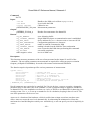
1 Introduction
This document is intended to serve as a reference guide to those who wish to program a PowerDNA
system. PowerDNA is the umbrella name that describes a real-time distributed I/O system with
exceptional flexibility and performance. It consists of PowerDNA Cubes (also known as I/O Modules,
or IOMs) that are distributed throughout a process or large piece of equipment, and a dedicated
Ethernet interface card plugged into a host computer. A host system can communicate with IOMs over
conventional Ethernet, using copper or fiber optic cables. If hard real-time response is required, the
host computer should have a real-time OS running. To achieve hard real-time performance on
commercial Ethernet cabling, a Central Controller comes with firmware that implements UEI’s patentpending DaqBIOS protocol.
Each PowerDNA cube provides several slots or “layers” that hold a variety of analog and digital I/O
function modules. For full details on PowerDAQ hardware, including PowerDNA cubes and the
various I/O Layers you can select, please go to www.PowerDNA.com
This document gives further details about the features and functionality of various system components.
It also provides an overview of all API functions that a designer employs to create a user application.
In broad terms, a user application uses function calls from the PowerDAQ API shared library. These
functions in turn use DaqBIOS commands that run the DaqBIOS Engine, the firmware that allow the
host or Central Controller to communicate with the PowerDNA cubes, sending operating commands
and retrieving data.
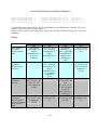
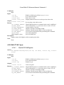
2 Five ways to communicate with IOM
The PowerDNA API provides five ways of communicating with the PowerDNA cube:
1. DaqBIOS Command API – so-called low-level commands (point-by-point synchronous)
2. Buffered I/O in continuous or burst mode (asynchronous) – see DqAcb functions
3. Mapped I/O (synchronous) – see DqDmap (fixed data size) and DqVmap (variable data size)
functions
4. Messaging I/O (asynchronous) – see DqMsg functions
5. Memory mapped mode (M3, asynchronous) – see DqMm functions
All three APIs can be used to communicate with a single IOM, but not at the same time. Once your
system is switched into one of asynchronous modes, it is recommended that you not issue synchronous
commands so as to avoid interfering with the PowerDNA cube configuration and timing set up for
asynchronous mode.
-1-
PowerDNA API Reference Manual, Release 4.0
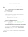
DaqBIOS Command API
The DaqBIOS Command API is a direct copy of DaqBIOS commands to the IOM. Every DaqBIOS
command has its equivalent in the PowerDNA (PDNALib) library.
Any code using the PowerDNA Library must include the file, PDNA.h, which itself includes all
necessary additional header files.
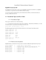
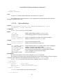
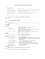
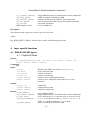
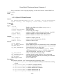
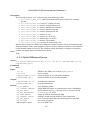
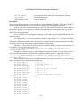
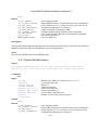
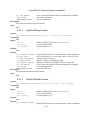
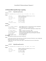
2.1 Pre-defined Types and Error Codes
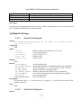
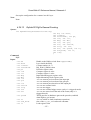
2.1.1 Pre-defined Types
These types are defined for use within the library.
DAQLIB is omitted from this document for the sake of readability. Under Microsoft Windows, it is used
for functions that are exported from the DAQLib dll for the user.
#define DAQLIB __declspec(dllexport) __stdcall
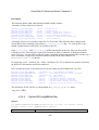
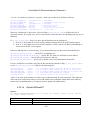
The following types keep the API call format similar across wide range of operating systems.
typedef unsigned long
typedef unsigned short
typedef unsigned char
u32;
u16;
u8;
typedef unsigned long
typedef unsigned short
typedef unsigned char
uint32;
uint16;
uint8;
typedef long
typedef short
typedef char
int32;
int16;
int8;
typedef unsigned long
typedef LPTSTR char*;
DWORD_PTR;
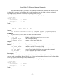
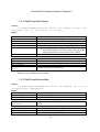
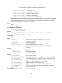
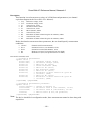
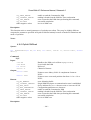
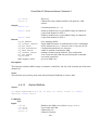
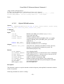
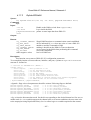
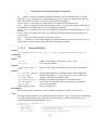
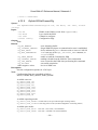
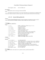
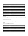
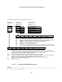
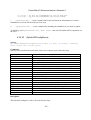
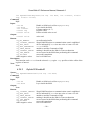
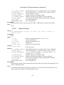
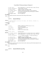
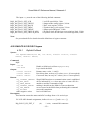
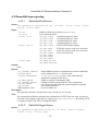
2.1.2 Devices and subsystems
DaqBIOS defines a maximum of 16 layers (devices) inside an IOM and eight subsystems per layer.
#define
#define
#define
#define
#define
#define
#define
#define
#define
#define
DQ_MAXDEVN
DQ_MAXSS
DQ_SS0IN
DQ_SS0OUT
DQ_SS1IN
DQ_SS1OUT
DQ_SS2IN
DQ_SS2OUT
DQ_SS3IN
DQ_SS3OUT
16
8
0
1
2
3
4
5
6
7
//
//
//
//
//
//
//
//
//
//
sixteen layers on the bus maximum
maximum number of subsystems (four input and four output)
Subsystem 0 input (main and often only device SS)
Subsystem 0 output (main and often only device SS)
Subsystem 1 input
Subsystem 1 output
Subsystem 2 input
Subsystem 2 output
Subsystem 3 input
Subsystem 3 output
-2-
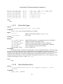
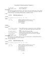
PowerDNA API Reference Manual, Release 4.0
The layer number is uint8. Only the four lower bits are used to signify the layer number. The upper
four bits have a special purpose. One of them is the DQ_LASTDEV (0x80) flag, which is used to mark
the last command entry in a DaqBIOS packet. The PowerDNA library handles use of DQ_LASTDEV,
so that a user never has to deal with it.
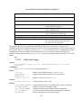
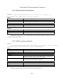
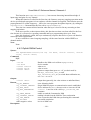
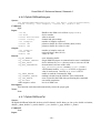
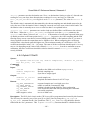
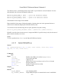
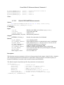
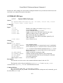
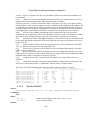
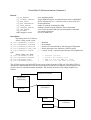
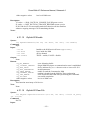
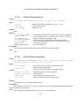
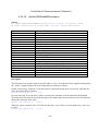
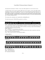
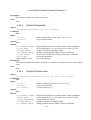
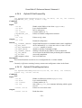
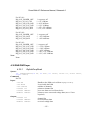
2.1.3 DaqBIOS Packet Structures
DaqBIOS protocol runs on top of UDP protocol. DaqBIOS packet has the following structure:
typedef struct {
uint32 dqProlog;
uint16 dqTStamp;
uint16 dqCounter;
uint32 dqCommand;
uint32 rqId;
uint8 dqData[];
} DQPKT, * pDQPKT;
/*
/*
/*
/*
/*
/*
const 0xBABAFACA */
16-bit timestamp */
Retry counter + bitfields */
DaqBIOS command */
Request ID - sent from host, mirrored */
Data */
The maximum size of a DaqBIOS packet (including this header) is limited to 530 bytes.
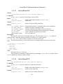
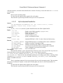
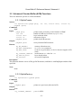
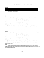
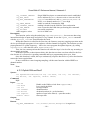
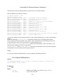
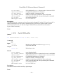
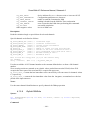
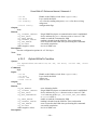
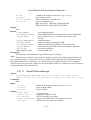
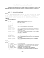
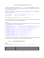
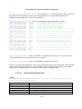
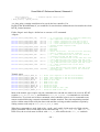
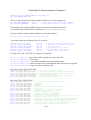
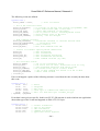
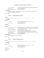
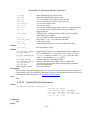
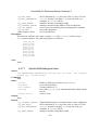
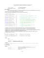
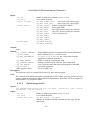
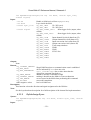
2.1.4 Error Codes
The following error codes are generated in firmware and can be returned from the IOM in the
dqCommand field of a DaqBIOS packet:
/* Masks to extract DQERR_... from command code */
#define DQERR_MASK
0xFFFF0000
#define DQNOERR_MASK
0x0000FFFF
/* The first nybble indicates how the
#define DQERR_NYBMASK
0xF0000000 /*
#define DQERR_MULTFAIL 0x80000000 /*
#define DQERR_SINGFAIL 0x90000000 /*
#define DQERR_BITS
next three nybbles should be interpreted */
general error/status mask */
high bit - multiple bits indicate error/status */
low bit in first nybble - single error/status */
0x0FFF0000 /* error/status bits or value extracted from here */
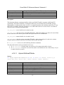
/* multiple errors - inclusive or-ed with dqCommand -- high bit set */
#define DQERR_GENFAIL
0xF0000000 /* general error/status mask */
#define DQERR_OVRFLW
0x80010000 /* Data extraction too slow - data overflow */
#define DQERR_STARTED
0x80020000 /* Start trigger is received */
#define DQERR_STOPPED
0x80040000 /* Stop trigger is received */
/* single errors/status
#define DQERR_EXEC
#define DQERR_NOMORE
#define DQERR_MOREDATA
#define DQERR_TOOOLD
#define DQERR_INVREQ
#define DQERR_NIMP
#define DQERR_ACCESS
#define DQERR_LOCKED
- not inclusive or-ed bit 0x10000000 set */
0x90010000 /* exception on command execution */
0x90020000 /* no more data is available */
0x90030000 /* more data is available */
0x90040000 /* request is too old (RDFIFO) */
0x90050000 /* Invalid request number (RDFIFO) */
0x90060000 /* DQ not implemented or unknown command */
0x90070000 /* password is not cleared - access denied */
0x90080000 /* cube is locked */
-3-
PowerDNA API Reference Manual, Release 4.0
/*
** The following is reuse of the previous code
** in the different direction: host->IOM
** It means that there was no reply to one
** of the previous packets of the same type
** Made especially for RDALL, WRRD and RDFIFO
** commands.
*/
#define DQERR_OPS
0x90070000 /* IOM is in operation state */
#define DQERR_PARAM
0x90080000 /* Device cannot complete request with specified
parameters */
/* network errors */
#define DQERR_RCV
#define DQERR_SND
0x90090000 /* packet receive error */
0x900A0000 /* packet send error */
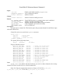
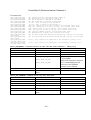
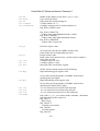
These codes are or-ed with command reply value (dqCommand | DQREPLY).
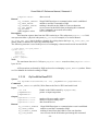
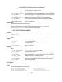
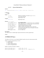
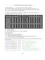
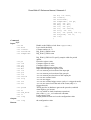
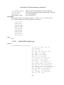
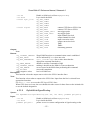
Another set of error codes can be generated on the host side:
#define DQ_NOERROR
#define DQ_SUCCESS
#define
#define
#define
#define
#define
#define
#define
#define
#define
#define
#define
#define
#define
#define
#define
#define
#define
#define
#define
#define
#define
#define
#define
#define
#define
DQ_ILLEGAL_ENTRY
DQ_ILLEGAL_HANDLE
DQ_SOCK_LIB_ERROR
DQ_TIMEOUT_ERROR
DQ_SEND_ERROR
DQ_RECV_ERROR
DQ_IOM_ERROR
DQ_PKT_TOOLONG
DQ_ILLEGAL_PKTSIZE
DQ_INIT_ERROR
DQ_BAD_PARAMETER
DQ_BAD_DEVN
DQ_NOT_IMPLEMENTED
DQ_NO_MEMORY
DQ_NOT_ENOUGH_ROOM
DQ_DEVICE_BUSY
DQ_EVENT_ERROR
DQ_BAD_CONFIG
DQ_DATA_ERROR
DQ_DEVICE_NOTREADY
DQ_CALIBRATION_ERROR
DQ_WRONG_DMAP
DQ_DATA_NOT_AVAILABLE
DQ_FIFO_OVERFLOW
DQ_ILLEGAL_INDEX
0
1
(-1)
(-2)
(-3)
(-4)
(-5)
(-6)
(-7)
(-8)
(-9)
(-10)
(-11)
(-12)
(-13)
(-14)
(-15)
(-16)
(-17)
(-18)
(-19)
(-20)
(-21)
(-22)
(-23)
(-24)
(-25)
// no error encountered
// success
//
//
//
//
//
//
//
//
//
//
//
//
//
//
//
//
//
//
//
//
//
//
//
//
//
illegal entry in parameters
illegal IOM handle (index)
socket error
command returns upon timeout
packet sending error
packet receiving error
IOM reports an unrecoverable error
too much data to fit a packet
packet size too small or too large
IOM initialization error
Invalid parameter passed
incorrect DEVN
bad luck - not implemented yet
not enough memory
not enough room in the packet/structure
somebody else uses this device
event handling error
bad configuration reported by DQCMD_RDSTS
layer returned invalid data
device is not ready
error while performing calibration
requested and received dmapid's do not match
requested data is not available
device FIFO overflowed
illegal index supplied
#define DQ_ERR_NEGATIVE_RETURN 0x80000000
// invert return code
As a general rule, you should check the return code from function calls for a negative number, which
indicates that an error has occurred.
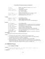
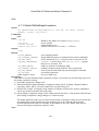
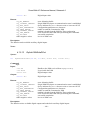
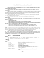
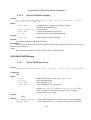
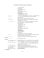
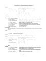
2.2 Auxiliary Functions
-4-
PowerDNA API Reference Manual, Release 4.0
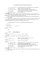
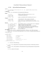
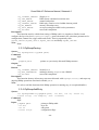
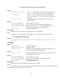
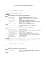
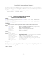
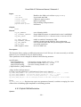
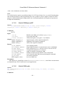
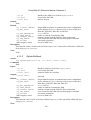
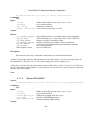
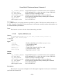
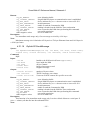
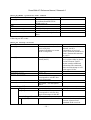
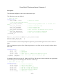
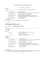
2.2.1 DqTranslateError
Syntax:
char *DqTranslateError(int error)
Input:
int error
Error code (negative) returned by previous
DaqBIOS API call
Output:
None
Return:
Pointer to ASCIIZ string describing this error (const char)
Description:
Converts error code into string
Note:
Windows implementation returns LPTSTR type
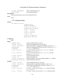
2.2.2 DqInitDAQLib
Syntax:
int DqInitDAQLib(void)
Input:
None
Output:
None
Return:
DQ_SOCK_LIB_ERROR
Windows WSAStartup() error
DQ_INIT_ERROR
Error allocating memory
DQ_SUCCESS
Command processed successfully
Description:
Loads the socket libraries and initializes table structures
Note:
This function should be called at the beginning of your program to allow the library to allocate
required resources and data structures after it is loaded. This function should not be called under
Windows, because Windows will automatically call it when loading the DLL.
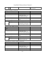
2.2.3 DqCleanUpDAQLib
Syntax:
void DqCleanUpDAQLib(void)
Input:
None
Output:
None
Return:
None
Description:
-5-
PowerDNA API Reference Manual, Release 4.0
Closes socket libraries and deallocates table structures.
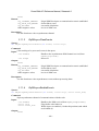
Note:
This function should be called at the end of your program, to allow the library to release
resources and clean up its allocated structures before it is unloaded. This function should not be called
under Windows, because Windows will automatically call it when unloading the DLL.
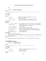
2.2.4 DqGetLibVersion
Syntax:
uint32 DqGetLibVersion(void)
Input:
None
Output:
None
Return:
Version of PDNA Library
Description:
Library version returns as 0xMMNNSS, where M is major version, N is minor version and S is
release subversion.
Note:
Versions with the same minors and different subversions have compatible APIs
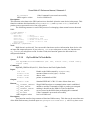
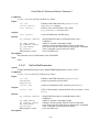
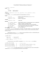
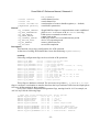
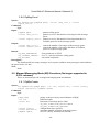
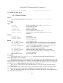
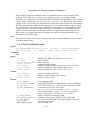
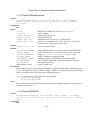
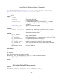
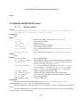
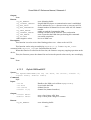
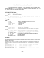
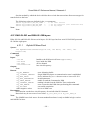
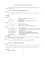
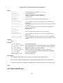
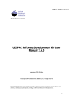
2.2.5 DqOpenIOM
Syntax:
int DqOpenIOM(char *IP, uint16 UDP_Port, uint32 mTimeOut, int
*handle, pDQRDCFG *pDqCfg);
Input:
char *IP
IP Address in Decimal dot Notation
uint16 UDP_Port
UDP port for use by the IOM
uint32 mTimeOut
Timeout Duration in milliseconds
int *handle
pointer to store descriptor of the IOM being opened
pDQRDCFG *pDqCfg
pointer to store pointer to DQCMD_ECHO results, or NULL if
not required
Output:
int *handle
descriptor of the IOM being opened
pDQRDCFG *pDqCfg
pointer to stored DQRDCFG structure resulting from
DQCMD_ECHO command or NULL upon error
Return:
DQ_SOCK_LIB_ERROR error opening socket or connecting to server
DQ_NO_MEMORY
memory allocation error or exceeded maximum table size
DQ_IOM_ERROR
IOM reports command execution error
DQ_SEND_ERROR
unable to send a packet to the IOM
DQ_TIMEOUT_ERROR
IOM reply wasn't received within timeout period
DQ_SUCCESS
if the IOM was successfully opened
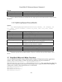
Description:
-6-
PowerDNA API Reference Manual, Release 4.0
This function opens communications with the IOM. If the IOM is successfully opened, it allows
function calls from this process. Normally, this function opens the descriptor of the network interface
and sends the DQCMD_ECHO command to the specified IP address to retrieve the IOM serial number,
layer types, model, calibration dates, etc. Upon retrieval of the DQRDCFG information, it stores it in the
IOM table. If the DQCMD_ECHO command fails, the function returns a NULL in pDqCfg. If the
DQRDCFG information is not desired, pass NULL as pDqCfg.
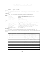
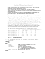
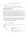
The returning packet payload has the following structure:
/* device configuration data */
typedef struct {
uint32 model;
/*
uint32 ipaddr;
/*
uint32 sernum;
/*
uint32 caldate;
/*
uint32 mfgdate;
/*
uint16 devmod[DQ_MAXDEVN]; /*
uint16 option[DQ_MAXDEVN]; /*
} DQRDCFG, *pDQRDCFG;
IOM model */
ip address */
serial number */
calibration date */
manufacturing date */
up to 16 installed layers */
and their option parameters */
Calibration and manufacturing dates are represented as 0xMMDDYYYY in uint32, where MM is
month, DD is day of the month and YYYY is year.
Note:
If the configuration from the IOM wasn’t requested or if the function returned a configuration
retrieval error, DQE will attempt to retrieve IOM configuration when Dq…InitOps() is called.
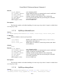
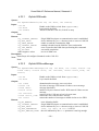
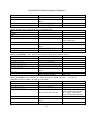
2.2.6 DqCloseIOM
Syntax:
void DqCloseIOM(int Iom)
Input:
int Iom
Handle to the IOM returned by DqOpenIOM()
Output:
None
Return:
DQ_ILLEGAL_HANDLE invalid IOM Descriptor
DQ_SUCCESS
successful completion
Description:
The function closes communication with the IOM and de-allocates all resources involved.
Note:
None
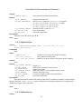
2.2.7 DqGetDevnBySlot
Syntax:
int DqGetDevnBySlot(int Iom, uint32 Slot, uint32* devn, uint32*
serial, uint32* address, uint16* model)
Input:
int Iom
Handle to the IOM returned by DqOpenIOM()
-7-
PowerDNA API Reference Manual, Release 4.0
uint32 Slot
The DNR chassis slot to query
uint32*
uint32*
uint32*
uint16*
Device number of the device sitting in the specified slot
Serial number of the device sitting in the specified slot
Address of the device sitting in the specified slot
Model number of the device sitting in the specified slot
Output:
devn
serial
address
model
Return:
DQ_ILLEGAL_HANDLE invalid IOM Descriptor
DQ_BAD_PARAMETER
The specified slot is empty or invalid
DQ_SUCCESS
successful completion
Description:
The function returns the ID number as well as other parameters for the device inserted in a
given slot.
Note:
This function is only useful with PowerDNR chassis. On PowerDNA I/O modules the device
number is always the position of the device in the stack.
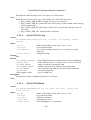
2.2.8 DqGetDevnBySerial
Syntax:
int DqGetDevnBySerial(int Iom, uint32 Serial, uint32* devn,
uint32* slot, uint32* address, uint16* model)
Input:
int Iom
Handle to the IOM returned by DqOpenIOM()
uint32 Serial
The serial number of the device to query
Output:
uint32* devn
Device number of the device matching the serial number
uint32* slot
Slot of the device matching the serial number
uint32* address
Address of the device matching the serial number
uint16* model
Model number of the device matching the serial number
Return:
DQ_ILLEGAL_HANDLE invalid IOM Descriptor
DQ_BAD_PARAMETER
The specified serial number was not found
DQ_SUCCESS
successful completion
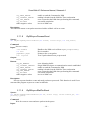
Description:
The function returns the ID number as well as other parameters for the device with a given
serial number.
Note:
None
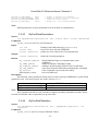
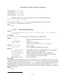
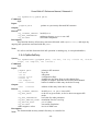
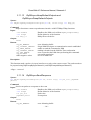
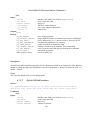
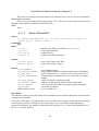
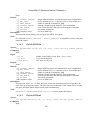
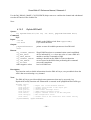
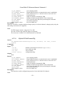
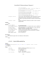
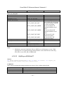
2.2.9 DqSetPacketSize
Syntax:
int DqSetPacketSize(int Iom, uint32 MinPktSize, uint32
MaxPktSize)
-8-
PowerDNA API Reference Manual, Release 4.0
Input:
int Iom
uint32 MinPktSize
uint32 MaxPktSize
Handle to the IOM returned by DqOpenIOM()
minimum size of UDP packet to send1
maximum size of UDP packet to send2
Output:
None
Return:
DQ_ILLEGAL_HANDLE
invalid Descriptor
DQ_ILLEGAL_PKTSIZE invalid value for MinPktSize or MaxPktSize
DQ_NO_MEMORY
error allocating buffer
DQ_SUCCESS
successful completion
Description:
The function sets up the minimum and maximum allowed sizes of UDP DaqBIOS packets.
Note:
The maximum size of a DaqBIOS packet (including the DQPKT header) is limited to 530
bytes.
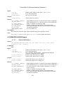
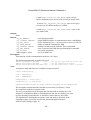
2.2.10
DqSetTimeout
Syntax:
int DqSetTimeout(int Iom, pDQE pDqe, int Timeoutms)
Input:
int Iom
Handle to the IOM
pDQE pDqe
DQ Engine pointer, or NULL if not using DQE
int Timeoutms
timeout value in milliseconds
Output:
None
Return:
DQ_ILLEGAL_HANDLE invalid Descriptor
DQ_BAD_PARAMETER
Timeoutms is negative
DQ_SUCCESS
command processed successfully
Description:
Changes the maximum allowed wait time for a reply packet (IOM must be open).
Note:
If (pDqe != NULL), the function sets the total timeout for every DQ command handled by
DQE. To calculate reply timeout, the total timeout is divided by number of retries allowed. If pDqe is
not specified, the function sets the timeout that applies only to the specified IOM.
2.2.11
DqReadSrec
Syntax:
int DqReadSrec(char *filename, int relative, uint32 size, char
*buffer, uint32 *bytes)
Command:
1
2
Setting minimum size is possibly not useful.
Limit maximum size for faster response.
-9-
PowerDNA API Reference Manual, Release 4.0
DAQLib
Input:
char *filename
int relative
uint32 size
char *buffer
uint32 *bytes
file name of .S19 S-Record file
TRUE to honor addresses read from the file, FALSE to read
data sequentially and ignore addresses
size of user buffer
pointer to user buffer
pointer to receive number of bytes written to buffer
Output:
char *buffer
raw data from .S19 S-Record file
uint32 *bytes
number of bytes written to buffer
Returns:
DQ_BAD_PARAMETER
if any parameter is NULL
DQ_SUCCESS
successful completion
Description:
Reads S-Record (.S19) file and converts it to binary data.
If relative is TRUE: This function considers the first address it encounters as the beginning
of the buffer, and all other addresses relative to the beginning of the buffer. Any addresses outside the
range the buffer can hold will be silently dropped.
If relative is FALSE: This function will read all data sequentially into the buffer, despite
the addresses indicated in the S-Records.
Note:
None
2.2.12
DqGetLastStatus
Syntax:
int DqGetLastStatus(int iom, uint32 *data, uint32 *size)
Input:
int iom
Handle to the IOM
uint32 *data
buffer to copy status data into
uint32 *size
size of buffer (number of 32-bit values)
Output:
uint32 *size
returns amount of data copied into data parameter, in 32-bit
chunks
Return:
DQ_ILLEGAL_HANDLE
illegal IOM Descriptor
DQ_BAD_PARAMETER
data or size parameter was NULL
DQ_NOT_ENOUGH_ROOM size passed in is too small to hold the data
DQ_RECV_ERROR
no status data has been received yet
DQ_SUCCESS
successful completion
Description:
Gets the last status data retrieved via the heartbeat.
Note:
None.
- 10 -
PowerDNA API Reference Manual, Release 4.0
2.2.13
DqReadAIChannel
Syntax:
int DqReadAIChannel(int hd, int devn, int samplesz, uint32
CLSize, uint32 *cl, uint8 *data)
Input:
int hd
Handle to the IOM
int devn
device number
int samplesz
size of one sample, in bytes
uint32 CLSize
channel list size
uint32 *cl
channel list
uint8 *data
array to store data (should be of CL size times sample size)
Output:
uint8 *data
received data
Return:
DQ_ILLEGAL_HANDLE
illegal IOM Descriptor or communication wasn’t established
DQ_SEND_ERROR
unable to send the Command to IOM
DQ_TIMEOUT_ERROR
nothing is heard from the IOM for Time out duration
DQ_IOM_ERROR
error occurred at the IOM when performing this command
DQ_SUCCESS
if the Command is processed successfully
Other negative values
low level IOM error
Description:
This function reads data from an analog input device.
Note:
Include DQ_INSTMODE_NTOH flag in samplesz parameter to automatically convert data
from network byte order to host byte order.
2.2.14
DqWriteAOChannel
Syntax:
int DqWriteAOChannel(int hd, int devn, int samplesz, uint32
CLSize, uint32* cl, uint8* data)
Input:
int hd
Handle to the IOM
int devn
device number
int samplesz
size of one sample, in bytes
uint32 CLSize
channel list size
uint32 *cl
channel list
uint8 *data
array of data (should be of CL size times sample size)
Output:
uint8 *data
received data
Return:
DQ_ILLEGAL_HANDLE
illegal IOM Descriptor or communication wasn’t established
DQ_SEND_ERROR
unable to send the Command to IOM
DQ_TIMEOUT_ERROR
nothing is heard from the IOM for Time out duration
DQ_IOM_ERROR
error occurred at the IOM when performing this command
DQ_SUCCESS
if the Command is processed successfully
Other negative values
low level IOM error
- 11 -
PowerDNA API Reference Manual, Release 4.0
Description:
This function writes data to an analog output device.
Note:
Include DQ_INSTMODE_NTOH flag in samplesz parameter to automatically convert data
from host byte order to network byte order.
2.2.15
DqCmdEcho
Syntax:
int DqCmdEcho(int Iom, pDQRDCFG pDQRdCfg)
Command:
DQCMD_ECHO (0x104), Echo
Input:
int Iom
Handle to the IOM returned by DqOpenIOM()
pDQRDCFG pDQRdCfg pointer to DQRDCFG structure allocated by calling process
Output:
pDQRDCFG pDQRdCfg pointer to populated DQRDCFG structure allocated by calling
process
Return:
DQ_ILLEGAL_HANDLE illegal IOM Descriptor or communication wasn’t established
DQ_IOM_ERROR
IOM reports command execution error
DQ_SEND_ERROR
cannot send packet
DQ_TIMEOUT_ERROR
IOM reply wasn’t received within timeout period
DQ_SUCCESS
if the Command is processed successfully
Other negative values
low level IOM error
Description:
Specified IOM replies back to the host with configuration data.
The returning packet payload has the following structure:
/* device configuration data */
typedef struct {
uint32 model;
/*
uint32 ipaddr;
/*
uint32 sernum;
/*
uint32 caldate;
/*
uint32 mfgdate;
/*
uint16 devmod[DQ_MAXDEVN]; /*
uint16 option[DQ_MAXDEVN]; /*
} DQRDCFG, *pDQRDCFG;
IOM model */
ip address */
serial number */
calibration date */
manufacturing date */
up to 16 installed layers */
and their option parameters */
Calibration and manufacturing dates are represented as 0xMMDDYYYY in uint32, where MM is
month, DD is day of the month and YYYY is year.
Note:
This is a safe command in any mode.
2.2.16
DqCmdReset
Syntax:
- 12 -
PowerDNA API Reference Manual, Release 4.0
int DqCmdReset(int Iom)
Command:
DQCMD_RST (0x110), Reset Device
Input:
int Iom
Handle to the IOM returned by DqOpenIOM()
Output:
None
Return:
DQ_ILLEGAL_HANDLE illegal IOM Descriptor or communication wasn’t established
DQ_SEND_ERROR
cannot send packet
DQ_SUCCESS
if the Command is processed successfully
Other negative values
low level IOM error
Description:
Resets the device specified. After this command, a device considers itself "initialized" and
switches to Init mode.
Note:
This command cannot be called in Operation mode. A device does not return from reset
immediately. Device becomes unavailable for network operations until reboot (approximately 5-10
seconds.)
2.2.17
DqCmdHwReset
Syntax:
int DqCmdHwReset(int Iom)
Command:
DQCMD_RST (0x110), Reset Device
Input:
int Iom
Handle to the IOM returned by DqOpenIOM()
Output:
None
Return:
DQ_ILLEGAL_HANDLE illegal IOM Descriptor or communication wasn’t established
DQ_SEND_ERROR
cannot send packet
DQ_SUCCESS
if the Command is processed successfully
Other negative values
low level IOM error
Description:
Performs full hardware reset on the IOM specified. After this command, the IOM considers
itself "initialized" and switches to Init mode.
Note:
This command cannot be called in Operation mode. A device does not return from reset
immediately. A device becomes unavailable for network operation until reboot occurs (approximately
5-10 seconds.)
- 13 -
PowerDNA API Reference Manual, Release 4.0
2.2.18
DqCmdWriteVal
Syntax:
int DqCmdWriteVal(int Iom, uint32 Address, uint32 *Value)
Command:
DQCMD_WRVAL (0x114), Write Value to the Device
Input:
int Iom
Handle to the IOM returned by DqOpenIOM()
uint32 Address
IOM memory map address to write to
uint32 *Value
pointer to 32-bit value to write to Address
Output:
None
Return:
DQ_ILLEGAL_HANDLE illegal IOM Descriptor or communication wasn’t established
DQ_SEND_ERROR
unable to send the Command to IOM
DQ_TIMEOUT_ERROR
nothing is heard from the IOM for Time out duration
DQ_IOM_ERROR
error occurred at the IOM when performing this command
DQ_SUCCESS
if the Command is processed successfully
Other negative values
low level IOM error
Description:
This function writes Value to a physical Address on IOM.
Note:
This low-level function can be dangerous because all IOM address space, including layer
registers, is accessible.
This function is password-protected with user level password.
2.2.19
DqCmdReadVal
Syntax:
int DqCmdReadVal(int Iom, uint32 Address, uint32 *Value)
Command:
DQCMD_RDVAL (0x118), Read Value from the Device
Input:
int Iom
Handle to the IOM returned by DqOpenIOM()
uint32 Address
IOM memory map address to read from
uint32 *Value
pointer to buffer to store the value received from the device
Output:
uint32 *Value
value received from the device
Return:
DQ_ILLEGAL_HANDLE illegal IOM Descriptor or communication wasn’t established
DQ_SEND_ERROR
unable to send the Command to IOM
DQ_TIMEOUT_ERROR
nothing is heard from the IOM for Time out duration
DQ_IOM_ERROR
error occurred at the IOM when performing this command
DQ_SUCCESS
if the Command is processed successfully
Other negative values
low level IOM error
Description:
- 14 -
PowerDNA API Reference Manual, Release 4.0
Function reads Value from a physical Address on IOM.
Note:
This low-level function can be dangerous because all IOM address space is accessible.
Therefore, I/O layer triggers may be initiated when certain memory is read.
This function is password-protected with user level password
2.2.20
DqCmdWriteMultipleValues
Syntax:
int DqCmdWriteMultipleValues(int Iom, pDQWRVALM DQWrMultVal)
Command:
DQCMD_WRVALM (0x11C), Write Multiple Values to the Device
Input:
int Iom
Handle to the IOM returned by DqOpenIOM()
pDQWRVALM
pointer to the structure that defines what and where to write
DQWrMultVal
Output:
None
Return:
DQ_ILLEGAL_HANDLE illegal IOM Descriptor or communication wasn’t established
DQ_SEND_ERROR
unable to send the Command to IOM
DQ_TIMEOUT_ERROR
nothing is heard from the IOM for Time out duration
DQ_IOM_ERROR
error occurred at the IOM when performing this command
DQ_SUCCESS
if the Command is processed successfully
Other negative values
low level IOM error
Description:
This function writes defined values to defined addresses in DQWrMultVal.
You have to fill all fields of this structure to ensure correct operation.
This structure is used to read and write multiple addresses from and to IOM memory:
/* DQCMD_WRVALM structure
typedef struct {
uint32 addr;
//
int16
increment; //
uint8
size;
//
uint8
count;
//
uint8
data[];
} DQWRVALM, *pDQWRVALM;
*/
address to write value
address increment/decrement after each write
size of operand and four lower bits of increment
number of values to write
Note:
The maximum count is limited by the packet size. This low-level function can be dangerous to
use because all IOM address space is accessible. I/O layer triggers may be initiated when certain
memory is written.
This function is password-protected with user level password.
2.2.21
DqCmdReadMultipleValues
Syntax:
- 15 -
PowerDNA API Reference Manual, Release 4.0
int DqCmdReadMultipleValues(int Iom, pwDQRDVALM pDQRdMultVal,
uint8 *Data)
Command:
DQCMD_RDVALM (0x120), Read Multiple Values from the Device
Input:
int Iom
Handle to the IOM returned by DqOpenIOM()
pwDQRDVALM
pointer to the structure defining what and where to read
pDQRdMultVal
uint8 *Data
pointer to store data received from the PowerDNA cube
Output:
uint8 *Data
data received from the PowerDNA cube
Return:
DQ_ILLEGAL_HANDLE illegal IOM Descriptor or communication wasn’t established
DQ_SEND_ERROR
unable to send the Command to IOM
DQ_TIMEOUT_ERROR
nothing is heard from the IOM for Time out duration
DQ_IOM_ERROR
error occurred at the IOM when performing this command
DQ_SUCCESS
if the Command is processed successfully
Other negative values
low level IOM error
Description:
This function reads multiple values from a physical address on IOM. You have to initialize
pwDQRDVALM structure before calling it.
/* DQCMD_RDVALM structure */
typedef struct {
uint32 addr;
int16
increment;
uint8
size;
uint8
count;
} wDQRDVALM, *pwDQRDVALM;
Note:
The maximum count is limited by the packet size. This low-level function can be dangerous to
use because all IOM address space is accessible. I/O layer triggers may be initiated when certain
memory is read.
This function is password-protected with user level password
2.2.22
DqCmdSetCfg
Syntax:
int DqCmdSetCfg(int Iom, DQSETCFG pDQSetCfg[], uint32 *Status,
uint32 *entries)
Command:
DQCMD_SETCFG (0x124), Set Configuration for the Device.
Input:
int Iom
Handle to the IOM returned by DqOpenIOM()
DQSETCFG
Array of configuration structures
pDQSetCfg[]
uint32 *Status
Array to store status information from all configured devices
uint32 *entries
Number of configuration structures passed in pDQSetCfg.
- 16 -
PowerDNA API Reference Manual, Release 4.0
Output:
uint32 *Status
uint32 *entries
Array of status values for the devices
Returns number of entries actually processed
DQ_ILLEGAL_HANDLE
DQ_SEND_ERROR
DQ_TIMEOUT_ERROR
DQ_IOM_ERROR
DQ_SUCCESS
Other negative values
illegal IOM Descriptor or communication wasn’t established
unable to send the Command to IOM
nothing is heard from the IOM for Time out duration
error occurred at the IOM when performing this command
if the Command is processed successfully
low level IOM error
Return:
Description:
This function sets up configuration of the PowerDNA cube. You must supply an array of
DQSETCFG structures.
The following structure is used in DQCMD_SETCFG command to set up configuration of the
layer. Multiple structures in the packet are allowed. The last device number must be or-ed with
LASTDEV (0x80).
/* DQCMD_SETCFG */
typedef struct {
uint8 dev; // device
uint8 ss;
// subsystems
uint32 cfg;
} DQSETCFG, *pDQSETCFG;
Configuration flags are divided into a standard part (common for all layer types) and a layerspecific part. Common flags are:
// Standard part (lower 16 bits) of layer configuration word
//
#define DQ_LN_RAW32
(1L<<18) // copy timestamp along with the data
#define DQ_LN_MAPPED
(1L<<15) // For WRRD (DQDMAP) devices
#define DQ_LN_STREAMING (1L<<14) // For RDFIFO devices - stream the FIFO data automatically
// For WRFIFO - do NOT send reply to WRFIFO unless needed
#define DQ_LN_RECYCLE
(1L<<13) // if there is no data taken/available overwrite/reuse data
#define DQ_LN_GETRAW
(1L<<12) // force layer to return raw unconverted data
#define DQ_LN_TMREN
(1L<<11) // enable layer periodic timer
#define DQ_LN_IRQEN
(1L<<10) // enable layer irqs
#define DQ_LN_PTRIGEDGE1 (1L<<9)
// stop trigger edge MSB
#define DQ_LN_PTRIGEDGE0 (1L<<8)
// stop trigger edge: 00 - software, 10 - external
#define DQ_LN_STRIGEDGE1 (1L<<7)
// start trigger edge MSB
#define DQ_LN_STRIGEDGE0 (1L<<6)
// start trigger edge: 00 - software, 10 - external
#define DQ_LN_CVCKSRC1
(1L<<5)
// CV clock source MSB
#define DQ_LN_CVCKSRC0
(1L<<4)
// CV clock source 0 - SW, 01 - internal, 10 - exterrnal
#define DQ_LN_CLCKSRC1
(1L<<3)
// CL clock source MSB
#define DQ_LN_CLCKSRC0
(1L<<2)
// CL clock source 0 - SW, 01 - internal, 10 - external
#define DQ_LN_ACTIVE
(1L<<1)
// "ACT" LED status
#define DQ_LN_ENABLED
(1L<<0)
// enable operations
Please refer to the layer-specific section in the user manual for layer-specific configuration
flags.
Note:
None
- 17 -
PowerDNA API Reference Manual, Release 4.0
2.2.23
DqCmdReadStatus
Syntax:
int DqCmdReadStatus(int Iom, uint8 *DeviceNum, uint32 *Entries,
uint32 *Status, uint32 *StatusSize)
Command:
DQCMD_RDSTS (0x118), Read Device Status
Input:
int Iom
Handle to the IOM returned by DqOpenIOM()
uint8 *DeviceNum
Array of layer numbers to retrieve status from
uint32 *Entries
Number of entries in DeviceNum array
uint32 *Status
Pointer to buffer to store values received from the device
uint32 *StatusSize Size of buffer, in 32-bit chunks.
Output:
uint32 *Entries
Actual number of entries requested
uint32 *Status
Array of device status requested
uint32 *StatusSize Number of 32-bit values copied into Status
Return:
DQ_ILLEGAL_HANDLE
illegal IOM Descriptor or communication wasn’t established
DQ_SEND_ERROR
unable to send the Command to IOM
DQ_TIMEOUT_ERROR
nothing is heard from the IOM for Time out duration
DQ_IOM_ERROR
error occurred at the IOM when performing this command
DQ_NOT_ENOUGH_ROOM StatusSize is too small to hold the data
DQ_SUCCESS
if the Command is processed successfully
Other negative values
low level IOM error
Description:
This function returns 128 bits of status per subsystem for each device specified. The following
constants are defined for analyzing the returned status:
The 4th uint32 contains the layer's logic status (not implemented for logic below version
10.00):
#define
#define
#define
#define
#define
#define
#define
#define
#define
#define
STS_LOGIC_DC_OOR
STS_LOGIC_DC_FAILED
STS_LOGIC_TRIG_START
STS_LOGIC_TRIG_STOP
STS_LOGIC_CLO_NOT_RUNNING
STS_LOGIC_CLI_NOT_RUNNING
STS_LOGIC_CVCLK_CLO_ERR
STS_LOGIC_CVCLK_CLI_ERR
STS_LOGIC_CLCLK_CLO_ERR
STS_LOGIC_CLCLK_CLI_ERR
(1UL<<0)
(1UL<<1)
(1UL<<2)
(1UL<<3)
(1UL<<4)
(1UL<<5)
(1UL<<6)
(1UL<<7)
(1UL<<8)
(1UL<<9)
//
//
//
//
//
//
//
//
//
//
DC/DC out of range (IOM also)
DC/DC failed (IOM also)
Trigger event started (IOM also)
Trigger event stopped (IOM also)
Output channel list not running
Input channel list not running
CV clock error for CLO
CV clock error for CLI
CL clock error for CLO
CL clock error for CLI
The first four error flags, DC_OOR, DC_FAILED, TRIG_START, and TRIG_STOP, are used
in the IOM status as well.
The 3rd uint32 contains the firmware status:
#define
#define
#define
#define
#define
#define
#define
#define
#define
STS_FW_CLK_OOR
STS_FW_SYNC_ERR
STS_FW_CHNL_ERR
STS_FW_BUF_SCANS_PER_INT
STS_FW_BUF_SAMPS_PER_PKT
STS_FW_BUF_RING_SZ
STS_FW_BUF_PREFUF_SZ
STS_FW_BAD_CONFIG
STS_FW_BUF_OVER
(1UL<<0)
(1UL<<1)
(1UL<<2)
(1UL<<3)
(1UL<<4)
(1UL<<5)
(1UL<<6)
(1UL<<7)
(1UL<<8)
//
//
//
//
//
//
//
//
//
Clock out of range (IOM also)
Synchronization interface error (IOM also)
Channel list is incorrect
Buf setting error: scans/interrupt
Buf setting error: samples/packet
Buf setting error: FW buffer ring size
Buf setting error: Pre-buffering size
Layer cannot operate in current config
Firmware buffer overrun
- 18 -
PowerDNA API Reference Manual, Release 4.0
#define
#define
#define
#define
#define
#define
STS_FW_BUF_UNDER
STS_FW_LYR_FIFO_OVER
STS_FW_LYR_FIFO_UNDER
STS_FW_EEPROM_FAIL
STS_FW_GENERAL_FAIL
STS_FW_OPER_MODE
(1UL<<9)
(1UL<<10)
(1UL<<11)
(1UL<<12)
(1UL<<13)
(1UL<<14)
//
//
//
//
//
//
Firmware buffer underrun
Layer FIFO overrun
Layer FIFO underrun
Layer EEPROM failed
Layer general failure
Layer is in operation mode
Clock out of range (STS_FW_CLK_OOR) means that the call to the DqCmdSetClock() function
specified a clock rate that is not possible to achieve with that layer, taking channel/gain list into
consideration. For example, an AI-207 layer has a multiplexed front-end with a maximum aggregate
sampling rate of 16kS/s using the gain of 1. Thus, if a user specifies a sampling rate 2kS/s for 16
channels, this bit is going to be set (also, DqDmapInitOps() or else DqAcbInitOps() will return an
error).
A synchronization interface error (STS_FW_SYNC_ERR) indicates that the Sync interface was not
configured in a fashion that can provide proper clock signals.
A channel list incorrect error (STS_FW_CHNL_ERR) is set when one or more entries in the channel
list array supplied to the layer is incorrect for that particular layer.
The flags STS_FW_BUF_SCANS_PER_INT, STS_FW_BUF_SAMPS_PER_PKT, STS_FW_BUF_RING_SZ,
STS_FW_BUF_PREFUF_SZ set in ACB or Burst mode signify that the requested buffer settings cannot be
accepted in the current configuration. The reason may be an incorrect parameter for that particular
layer or an inability to allocate a proper buffer or function compatible with other layers in the stack.
The flag STS_FW_BAD_CONFIG is set when a layer configuration is improper for this layer or a
combination of layers.
The flags STS_FW_BUF_OVER and STS_FW_BUF_UNDER are set for input and output subsystems in
situations in which an internal buffer becomes full and there is no room to store more data (and one or
more samples are lost) or when an output buffer becomes empty (output stopped). These flags make
sense in ACB mode only.
The flags STS_FW_LYR_FIFO_OVER and STS_FW_LYR_FIFO_UNDER are similar to previous flags, but report
underrun/overrun status of FIFO circuitry located on each layer.
The flag STS_FW_EEPROM_FAIL is set when the layer E2PROM 32-bit cyclic redundancy code
(CRC32) calculated during the initialization stage does not match the CRC32 stored in the last four
bytes of the 2048-byte E2PROM chip.
The flag STS_FW_GENERAL_FAIL reports a general layer failure of unknown source detected by the
firmware.
The flag STS_FW_OPER_MODE is set when a layer is in operating mode. The layer enters operating
mode for DMap, ACB, Msg, M3, and Burst operations.
The first two error flags, CLK_OOR and SYNC_ERR, are used in the IOM status as well.
The 2nd uint32 of the IOM status only contains flags that indicate errors discovered during
POST (not implemented for firmware revisions 3.4 and below):
#define
#define
#define
#define
#define
#define
#define
STS_POST_MEMERR
STS_POST_EEPROM_CHK
STS_POST_LAYER_FAILED
STS_POST_FLASH_FAILED
STS_POST_SDCARD_FAILED
STS_POST_DC24
STS_POST_DCCORE
(1L<<0)
(1L<<1)
(1L<<2)
(1L<<3)
(1L<<4)
(1L<<5)
(1L<<6)
//
//
//
//
//
//
//
Memory test failed
E2PROM read failed
Layer failure
Flash checksum error
SD Card is not present
DC->24 layer failed
Core voltages problem
Note that when either the EEPROM_CHK or LAYER_FAILED flag is set, the
STS_FW_EEPROM_FAIL or STS_FW_GENERAL_FAIL flag, respectively, will also be set in the
appropriate layer’s status.
- 19 -
PowerDNA API Reference Manual, Release 4.0
Note:
1. Use device |= 0x80 to indicate that this is the last device in the list
2. IOM reads the status registers of the specified devices only
3. The DqVT packet can contain more entries, but the number of devices per IOM is limited to
8.
4. Use DeviceNum entry of 0x7F to get the status of the IOM itself
5. Use DeviceNum entry of 0x7E to get the status of IOM followed sequentially by all devices
present; this must be the only value used, and the result is always 128 bits per device, regardless of
subsystem count. Each error bit for a device represents the aggregate for all subsystems of that device;
in other words, an error bit will be set if at least one subsystem has that error bit set. You can then call
DqCmdReadStatus with the specific device number to find out which subsystem had the error.
2.2.24
DqCmdWriteChannel
Syntax:
int DqCmdWriteChannel(int Iom, pDQWRCHNL DQChannelData, uint32
DataBufLen)
Command:
DQCMD_WRCHNL (0x12C), Write Channel
Input:
int Iom
Handle to the IOM returned by DqOpenIOM()
pDQWRCHNL
Array of structures that define device, subsystem, channel, and
DQChannelData
data
uint32 DataBufLen Combined size in bytes of all structures contained in
DQChannelData
Output:
None.
Return:
DQ_ILLEGAL_HANDLE illegal IOM Descriptor or communication wasn’t established
DQ_SEND_ERROR
unable to send the Command to IOM
DQ_TIMEOUT_ERROR
nothing is heard from the IOM for Time out duration
Other values
low level IOM status
Description:
This function writes channels specified in DQWRCHNL structures.
The IOM firmware scans incoming data and passes subsystem and channel information to the
appropriate device driver.
The data field should be typecast to a data size appropriate to the device. For example, for
an AI-302, the data field should be typecast to uint16. See user manual for a complete list.
DQCMD_WRCHNL transfers data in the following format:
/* DQCMD_WRCHNL */
typedef struct {
uint8 dev;
uint8 ss;
uint8 chnl;
uint32 data;
- 20 -
PowerDNA API Reference Manual, Release 4.0
} DQWRCHNL, *pDQWRCHNL;
Note:
Use dev |= DQ_LASTDEV to indicate the last device in the list.
A channel may be a relative position in the programmed channel list but not an actual channel
number, depending on the hardware.
Since DMap mode is provided, there is only marginal use for this function,.
2.2.25
DqCmdReadChannel
Syntax:
int DqCmdReadChannel(int Iom, pDQRDCHNL pDQChannelData, void
*Data, uint32 *DataBufLen)
Command:
DQCMD_RDCHNL (0x130), Set Channel List
Input:
int Iom
Handle to the IOM returned by DqOpenIOM()
pDQRDCHNL
Array of structures that defines device and channel
DQChannelData
void *Data
pointer to buffer to store received data
uint32
size of the data buffer, bytes
*DataBufLen
Output:
void *Data
received data
uint32
returned size of the data in buffer, bytes
*DataBufLen
Return:
DQ_ILLEGAL_HANDLE illegal IOM Descriptor or communication wasn’t established
DQ_SEND_ERROR
unable to send the Command to IOM
DQ_TIMEOUT_ERROR
nothing is heard from the IOM for Timeout duration
DQ_IOM_ERROR
error occurred at the IOM when performing this command
DQ_SUCCESS
if the Command is processed successfully
Other negative values
low level IOM error
Description:
This function reads channels specified in DQRDCHNL structures.
The IOM firmware scans incoming data and passes subsystem and channel information to the
appropriate device driver. Firmware relies on user to set up DQ_LASTDEV for the last device structure
in the packet and proper size of data (accordingly to the layer type). For example, an AI-201 returns
uint16 for every channel requested, and an AI-205 and an AI-225 return uint32. See user manual
for a complete list.
Neither firmware nor the library performs network-to-host data conversion. The user is
responsible for converting data according to the layer types involved.
DQCMD_RDCHNL transfers data in the following format:
/* DQCMD_RDCHNL */
typedef struct {
uint8 dev;
uint8 ss;
- 21 -
PowerDNA API Reference Manual, Release 4.0
uint8 chnl;
} DQRDCHNL, *pDQRDCHNL;
Note:
Use device |= 0x80 to indicate that this is the last device in the list.
Since DMap mode is provided, there is only marginal use for this function. This function
interface is prone to user errors.
2.2.26
DqCmdSetClock
Syntax:
int DqCmdSetClock(int Iom, pDQSETCLK pDQSetClk, float
*CloseFreq, uint32 *entries)
Command:
DQCMD_SETCLK (0x134), Set Clock Rate
Input:
int Iom
Handle to the IOM returned by DqOpenIOM()
pDQSETCLK
clock settings (pointer to an array of structures)
pDQSetClk
float *CloseFreq
pointer to uninitialized variable (user allocates buffer)
uint32 *entries
number of entries in pDQSetClk array
Output:
float *CloseFreq
array of actual frequencies, Hz
uint32 *entries
pointer to actual number of entries set
Return:
DQ_ILLEGAL_HANDLE illegal IOM Descriptor or communication wasn’t established
DQ_SEND_ERROR
unable to send the Command to IOM
DQ_TIMEOUT_ERROR
nothing is heard from the IOM for Time out duration
DQ_IOM_ERROR
error occurred at the IOM when performing this command
DQ_SUCCESS
if the Command is processed successfully
Other negative values
low level IOM error
Description:
This function programs layer clocks, using the DQSETCLK structure.
The firmware selects the closest possible speed (due to a division remainder of base frequency
divided by requested rate). The function returns the actual rate in CloseFreq array.
DQCMD_SETCLK uses the following structure. Multiple entries are allowed.
/* DQCMD_SETCLK */
typedef struct {
uint8 dev;
// device number
uint8 ss;
// channel/subsystem/CVCL
uint8 clocksel; // select clock/trigger settings
float frq;
} DQSETCLK, *pDQSETCLK;
clocksel must contain one of the following bits:
// Clock identifiers
- 22 -
PowerDNA API Reference Manual, Release 4.0
#define
#define
#define
#define
#define
#define
#define
#define
DQ_LN_CLKID_DUTY1
DQ_LN_CLKID_DUTY0
DQ_LN_CLKID_TMR1
DQ_LN_CLKID_TMR0
DQ_LN_CLKID_CVIN
DQ_LN_CLKID_CVOUT
DQ_LN_CLKID_CLIN
DQ_LN_CLKID_CLOUT
(1L<<7)
(1L<<6)
(1L<<5)
(1L<<4)
(1L<<3)
(1L<<2)
(1L<<1)
(1L<<0)
//
//
//
//
//
//
//
//
Duty cycle of TMR1 (0 is a single pulse)
Duty cycle of TMR0 (0 is a single pulse)
TMR1 (burst clock)
TMR0 (conversion base clock)
CV Input SS clock
CV Output SS clock
CV Input SS clock
CV Output SS clock
Note:
None
2.2.27
DqCmdSwTrigger
Syntax:
int DqCmdSwTrigger(int Iom, uint32 Mask)
Command:
DQCMD_START (0x138), Start/Stop Devices by Mask
Input:
int Iom
Handle to the IOM returned by DqOpenIOM()
uint32 Mask
layer mask
Output:
None
Return:
DQ_ILLEGAL_HANDLE illegal IOM Descriptor or communication wasn’t established
DQ_SEND_ERROR
unable to send the Command to IOM
DQ_TIMEOUT_ERROR
nothing is heard from the IOM for Time out duration
DQ_IOM_ERROR
error occurred at the IOM when performing this command
DQ_SUCCESS
if the Command is processed successfully
Other negative values
low level IOM error
Description:
The function issues a software start trigger pulse. If the configuration defines a software trigger,
the layer will be programmed, but idle, from the moment of switching into operation state to the
moment of receiving a software trigger command (i.e. will not produce any data). The software trigger
command causes the logic to issue a start trigger pulse to start data conversion. Every bit in Mask
represents a layer in the device stack, where bit 0 corresponds with device 0, etc. For example, to issue
a software start trigger for layer 1, Mask = (1L << 1);
Note:
None
2.2.28
DqCmdSetChannelList
Syntax:
int DqCmdSetChannelList(int Iom, pDQSETCL pDQSetCl, uint32
*entries)
Command:
DQCMD_SETCL (0x13C)
- 23 -
PowerDNA API Reference Manual, Release 4.0
Input:
int Iom
pDQSETCL pDQSetCl
uint32 *entries
Handle to the IOM returned by DqOpenIOM()
array of channel list entries
number of entries
uint32 *entries
number of entries actually processed
Output:
Return:
DQ_ILLEGAL_HANDLE illegal IOM Descriptor or communication wasn’t established
DQ_SEND_ERROR
unable to send the Command to IOM
DQ_TIMEOUT_ERROR
nothing is heard from the IOM for Timeout duration
DQ_SUCCESS
if the Command is processed successfully
Other negative values
low level IOM error
Description:
Sets up the device channel list. This function parses the presented channel list and fills the input
and output channel lists.
Channel list entries are stored in the DQSETCL structures:
typedef struct {
uint8 dev;
// device number
uint8 ss;
// subsystem
uint32 entry; // channel list entry
} DQSETCL, *pDQSETCL;
The channel list has following format:
31 - 16
<flags>
15-12
<gain,mode>
11 - 0
<ch number>
Flags are defined as follows:
#define
#define
#define
#define
#define
#define
#define
#define
#define
#define
#define
#define
#define
#define
#define
#define
#define
DQ_LNCL_NEXT
DQ_LNCL_INOUT
DQ_LNCL_SS1
DQ_LNCL_SS0
DQ_LNCL_IRQ
DQ_LNCL_NOWAIT
DQ_LNCL_SKIP
DQ_LNCL_CLK
DQ_LNCL_CTR
DQ_LNCL_WRITE
DQ_LNCL_UPDALL
DQ_LNCL_TSRQ
DQ_LNCL_SLOW
DQ_LNCL_DIO
DQ_LNCL_RSVD1
DQ_LNCL_RSVD0
DQ_LNCL_DIFF
(1UL<<31)
(1UL<<30)
(1UL<<29)
(1UL<<28)
(1UL<<27)
(1UL<<26)
(1UL<<25)
(1UL<<24)
(1UL<<23)
(1UL<<22)
(1UL<<21)
(1UL<<20)
(1UL<<19)
(1UL<<18)
(1UL<<17)
(1UL<<16)
(1UL<<15)
//
//
//
//
//
//
//
//
//
//
//
//
//
//
//
//
//
channel list has next entry
(reserved for future use)
(reserved for future use)
(reserved for future use)
(reserved for future use)
(reserved for future use)
(reserved for future use)
(reserved for future use)
(reserved for future use)
write to the channel but not update
update all written channels
(reserved for future use)
slow down operation
write/read DIO
(reserved for future use)
(reserved for future use)
differential mode
Note:
DQCMD_SETCL is an additive function. Each time you write it, it adds a channel to the existing
channel list. Please reset the device to clear the channel list.
Only a few flags are supported by current set of layers: AI-201/205 (DQ_LNCL_SLOW,
DQ_LNCL_NEXT, DQ_LNCL_DIFF) or AO-302 (DQ_LNCL_WRITE, DQ_LNCL_UPDALL).
- 24 -
PowerDNA API Reference Manual, Release 4.0
2.2.29
DqCmdSetTransferList
Syntax:
int DqCmdSetTransferList(int Iom, pDQSETTRL pDQSetTrl)
Command:
DQCMD_SETTRL (0x140), Set Transfer List
Input:
int Iom
Handle to the IOM returned by DqOpenIOM()
pDQSETTRL pDQSetTrl transfer list descriptor
Output:
None.
Return:
DQ_ILLEGAL_HANDLE illegal IOM Descriptor or communication wasn’t established
DQ_SEND_ERROR
unable to send the Command to IOM
DQ_TIMEOUT_ERROR
nothing is heard from the IOM for Time out duration
DQ_IOM_ERROR
error occurred at the IOM when performing this command
DQ_SUCCESS
if the Command is processed successfully
Other negative values
low level IOM error
Description:
This function sets up a transfer list for DMap operations given by DQSETTRL structure.
DqCmdSetTransferList() has additive behavior. The firmware accumulates transfer lists
with the same dmapid in the memory. Every time the firmware finds a new dmapid, it allocates
memory to store a transfer list.
To set up a transfer list for a device, use the DQSETTRL structure.
/* DQCMD_SETTRL */
typedef struct {
uint16 dmapid;
uint8 dev;
uint8 ss;
uint32 ch;
uint32 flags;
uint16 samples;
} DQSETTRL, *pDQSETTRL;
//
//
//
//
//
//
DMAP id
device
subsystem
channel (channel list entry)
control flags, including channel information
number of samples from this channel
Note:
This function is called automatically in DqDmapInitOps().
2.2.30
DqCmdWriteAll
Syntax:
int DqCmdWriteAll(int Iom, pDQWRRD pDQWr)
Command:
DQCMD_WRRD (0x14C), Write All Data and Read Data Back
Input:
int Iom
Handle to the IOM returned by DqOpenIOM()
pDQWRRD pDQWr
data for output DMap
Return:
- 25 -
PowerDNA API Reference Manual, Release 4.0
DQ_ILLEGAL_HANDLE illegal IOM Descriptor or communication wasn’t established
DQ_SEND_ERROR
unable to send the Command to IOM
DQ_TIMEOUT_ERROR
nothing is heard from the IOM for Timeout duration
DQ_IOM_ERROR
error occurred at the IOM when performing this command
DQ_SUCCESS
if the Command is processed successfully
Other negative values
low level IOM error
Description:
This function initiates exchange of data as described by a transfer list. Caller must fill the
pDqWr structure with proper DMap Ids and specify size of the output data. Setting an input or output
DMap ID to zero disables transferring of data in that direction.
This function doesn’t wait for the IOM to reply with the input data. Call DqCmdReadAll() to
retrieve the input data.
This function is useful in a real-time environment where the real-time task can’t afford to wait
for the IOM’s response. DqCmdWriteAll() should be called at the end of the real-time cycle and
DqCmdReadAll() should be called at the beginning of the next cycle.
The following structure is used to exchange data during DMap operations:
/* DQCMD_WRRD */
typedef struct {
uint32 dmapid;
uint32 size;
uint8 data[];
} DQWRRD, *pDQWRRD;
// DMap ID
// size of data
// data
Note:
None
2.2.31
DqCmdReadAll
Syntax:
int DqCmdReadAll(int Iom, pDQWRRD pDQRd)
Command:
DQCMD_WRRD (0x14C), Write All Data and Read Data Back
Input:
int Iom
Handle to the IOM returned by DqOpenIOM()
pDQWRRD pDQRd
pointer to store input DMap data
Output:
pDQWRRD pDQRd
pointer to received input data
Return:
DQ_ILLEGAL_HANDLE illegal IOM Descriptor or communication wasn’t established
DQ_SEND_ERROR
unable to send the Command to IOM
DQ_TIMEOUT_ERROR
nothing is heard from the IOM for Time out duration
DQ_IOM_ERROR
error occurred at the IOM when performing this command
DQ_SUCCESS
if the Command is processed successfully
Other negative values
low level IOM error
Description:
This function reads the response from an IOM to a request to exchange data initiated by a call
to DqCmdWriteAll().
- 26 -
PowerDNA API Reference Manual, Release 4.0
This function is useful in a real-time environment where the real-time task can’t afford to wait
for the IOM’s response. DqCmdWriteAll() should be called at the end of the real-time cycle and
DqCmdReadAll() should be called at the beginning of the next cycle.
The following structure is used to exchange data during DMap operations:
/* DQCMD_WRRD */
typedef struct {
uint32 dmapid;
uint32 size;
uint8 data[];
} DQWRRD, *pDQWRRD;
// DMap ID
// size of data
// data
Note:
None
2.2.32
DqCmdWriteReadAll
Syntax:
int DqCmdWriteReadAll(int Iom, pDQWRRD pDQWr, pDQWRRD pDQRd)
Command:
DQCMD_WRRD (0x14C), Write All Data and Read Data Back
Input:
int Iom
Handle to the IOM returned by DqOpenIOM()
pDQWRRD pDQWr
data for output DMap
pDQWRRD pDQRd
pointer to store input DMap data
Output:
pDQWRRD pDQRd
pointer to received input data
Return:
DQ_ILLEGAL_HANDLE illegal IOM Descriptor or communication wasn’t established
DQ_SEND_ERROR
unable to send the Command to IOM
DQ_TIMEOUT_ERROR
nothing is heard from the IOM for Time out duration
DQ_IOM_ERROR
error occurred at the IOM when performing this command
DQ_SUCCESS
if the Command is processed successfully
Other negative values
low level IOM error
Description:
This function initiates exchange of data described by transfer list. Caller must fill pDqWr
structure with proper DMap Ids and specify size of input and output data. Setting input or output DMap
ID to zero disables transferring of data in that direction.
The following structure is used to exchange data during DMap operations:
/* DQCMD_WRRD */
typedef struct {
uint32 dmapid;
uint32 size;
uint8 data[];
} DQWRRD, *pDQWRRD;
// DMap ID
// size of data
// data
Note:
None
- 27 -
PowerDNA API Reference Manual, Release 4.0
2.2.33
DqCmdWriteFIFO
Syntax:
int DqCmdWriteFIFO(int Iom, pDQFIFO pDQFifo)
Command:
DQCMD_WRFIFO (0x150), Writes Data to Device FIFO
Input:
int Iom
Handle to the IOM returned by DqOpenIOM()
pDQFIFO pDQFifo
output data
Output:
pDQFifo->size
number of bytes actually transferred
Return:
DQ_ILLEGAL_HANDLE illegal IOM Descriptor or communication wasn’t established
DQ_SEND_ERROR
unable to send the Command to IOM
DQ_TIMEOUT_ERROR
nothing is heard from the IOM for Timeout duration
DQ_IOM_ERROR
error occurred at the IOM when performing this command
DQ_SUCCESS
if the Command is processed successfully
Other negative values
low level IOM error
Description:
This function writes data to the FIFO on the layer. The subsystem pDQFifo->ss field can
represent either a physical subsystem (SS0IN, for example) or a virtual channel.
DQ_FIFO_SET_DATA (0x10) defines a channel to write data to the layer.
The following structure is used in the process of exchanging data stream between host and
IOM:
/* DQCMD_WRFIFO and DQCMD_RDFIFO */
typedef struct {
uint8 dev;
uint8 ss;
uint16 size;
uint8 data[];
} DQFIFO, *pDQFIFO;
Note:
Maximum data size is 514 bytes.
ACB operations performed by DQE are based on exchanging DQCMD_WRFIFO packets. Please
see User Manual for internal working of DQE.
2.2.34
DqCmdReadFIFO
Syntax:
int DqCmdReadFIFO(int Iom, pDQFIFO pDQFifo)
Command:
DQCMD_RDFIFO (0x154), Read Device Data from the FIFO
Input:
int Iom
Handle to the IOM returned by DqOpenIOM()
pDQFIFO pDQFifo
pointer to store input data
Output:
pDQFifo->size
number of bytes actually transferred
- 28 -
PowerDNA API Reference Manual, Release 4.0
pDQFifo->data
data received
Return:
DQ_ILLEGAL_HANDLE illegal IOM Descriptor or communication wasn’t established
DQ_SEND_ERROR
unable to send the Command to IOM
DQ_TIMEOUT_ERROR
nothing is heard from the IOM for Time out duration
DQ_IOM_ERROR
error occurred at the IOM when performing this command
DQ_SUCCESS
if the Command is processed successfully
Other negative values
low level IOM error
Description:
This function requests data from the FIFO on the layer. The subsystem pDQFifo->ss field
can represent either a physical subsystem (DQ_SS0IN, for example) or a virtual channel.
DQ_FIFO_GET_DATA (0x10) defines a channel for writing data to the layer. DQ_FIFO_GET_CAL
(0x20) defines a channel for retrieving calibration data.
The following structure is used in the process of exchanging a data stream between host and IOM:
/* DQCMD_WRFIFO and DQCMD_RDFIFO */
typedef struct {
uint8 dev;
uint8 ss;
uint16 size;
uint8 data[];
} DQFIFO, *pDQFIFO;
Note:
The maximum data size is 514 bytes. pDQFifo->data must be at least pDQFifo->size
bytes in size.
ACB operations performed by DQE are based on exchanging DQCMD_RDFIFO packets. Please
see User Manual for internal workings of DQE.
2.2.35
DqCmdWriteReadFIFO
Syntax:
int DqCmdWriteReadFIFO(int Iom, pDQWRRDFIFO pDQWrRdFifo)
Command:
DQCMD_WRRDFIFO (0x158), Write Data to the Device FIFO and read it back
Input:
int Iom
Handle to the IOM returned by DqOpenIOM()
pDQWRRDFIFO
pointer to input/output data
pDQWrRdFifo
Output:
pDQWrRdFifo->sizew
number of bytes actually written
pDQWrRdFifo->sizer
number of bytes actually read
pDQWrRdFifo->data
data from the device
Return:
DQ_ILLEGAL_HANDLE illegal IOM Descriptor or communication wasn’t established
DQ_SEND_ERROR
unable to send the Command to IOM
DQ_TIMEOUT_ERROR
nothing is heard from the IOM for Time out duration
DQ_IOM_ERROR
error occurred at the IOM when performing this command
- 29 -
PowerDNA API Reference Manual, Release 4.0
DQ_SUCCESS
if the Command is processed successfully
Other negative values
low level IOM error
Description:
This function writes data to the FIFO and retrieves data back (from the same device/subsystem). This
function combines the functionality of DqCmdRdFifo() and DqCmdWrFifo() in one call. It
produces one request and receives one reply packet.
The following structure is used in the process of exchanging a data stream between host and
IOM:
/* DQCMD_WRRDFIFO */
typedef struct {
uint8 dev;
// device
uint8 ssw;
// subsystem
uint8 ssr;
// subsystem
uint16 sizew;
// amount of
uint16 sizer;
// amount of
uint8 data[];
} DQWRRDFIFO, *pDQWRRDFIFO;
to write
to read
data to write
data to read
Note:
DQE doesn’t use this call. You can use this function to retrieve information from device with
an input and output subsystem. If you select DQ_SS0IN as a subsystem to write, the function uses
DQ_SS0OUT as a subsystem to read. In other words, this function ignores the direction bit in
subsystem definition.
2.2.36
DqCmdWriteToFlashBuffer
Syntax:
int DqCmdWriteToFlashBuffer(int Iom, uint32 Size, uint8 *Data,
uint32 *CRC)
Command:
DQCMD_WRFLASH (0x15C), Write Data to the Flash Update Buffer
Input:
int Iom
Handle to the IOM returned by DqOpenIOM()
uint32 Size
amount of data to write, bytes, 0 to reset
uint8 *Data
data to write
uint32 *CRC
pointer to uninitialized CRC
Output:
uint32 *CRC
Standard IEEE 802.3 CRC-32 value of data from user
Return:
DQ_ILLEGAL_HANDLE illegal IOM Descriptor or communication wasn’t established
DQ_SEND_ERROR
unable to send the Command to IOM, or packet got corrupted
DQ_TIMEOUT_ERROR
nothing is heard from the IOM for Time out duration
DQ_IOM_ERROR
error occurred at the IOM when performing this command
DQ_SUCCESS
if the Command is processed successfully
Other negative values
low level IOM error
Description:
This function transfers large amount of data into IOM memory. This data can be stored into one
of the IOM flash memory locations upon a DqCmdUpdateFlashBuffer() call. Every time a user
- 30 -
PowerDNA API Reference Manual, Release 4.0
calls this function, it transfers data and allocates a chunk of memory to store this data. Set Size to 0 to
reset memory.
Note:
Do not call in operating mode.
Use the firmware update utility supplied for safe update.
This function is password-protected with super-user level password
2.2.37
DqCmdUpdateFlashBuffer
Syntax:
int DqCmdUpdateFlashBuffer(int Iom, uint16 Sector, uint32
Address, uint32 Size, uint32 *CRC)
Command:
DQCMD_UPDFLASH (0x160), Update Flash Data from the Flash Update Buffer
Input:
int Iom
Handle to the IOM returned by DqOpenIOM()
u16 sector
Flash sector to start from
u32 address
Flash chip address
u32 size
amount of data to write
uint32 *CRC
pointer to uninitialized CRC
Output:
uint32 *CRC
Standard IEEE 802.3 CRC-32 value of data in flash memory
Return:
DQ_ILLEGAL_HANDLE illegal IOM Descriptor or communication wasn’t established
DQ_SEND_ERROR
unable to send the Command to IOM
DQ_TIMEOUT_ERROR
nothing is heard from the IOM for Time out duration
DQ_IOM_ERROR
error occurred at the IOM when performing this command
DQ_SUCCESS
if the Command is processed successfully
Other negative values
low level IOM error
Description:
This function initiates a write operation into a firmware sector. The current CM-1 layer has two
flash chips that are located at different addresses. The system flash is located at
DQ_FLASH_ADDRESS and has a size of DQ_FLASH_SIZE. The firmware starts at sector
DQ_UPUSER_SEC. These are the only allowable parameters for writing system flash. Auxiliary flash
is located at DQ_FLASHAUX_ADDRESS and has a size of DQ_FLASHAUX_SIZE. All of auxiliary
flash is available to the user.
Note:
This is a pending command. Use a large timeout. Do not call in operating mode. This operation
takes tens of seconds to complete. At the time of Flash update, the device will be unreachable via
DaqBIOS.
Use the firmware update utility supplied for safe update.
This function is password-protected with super-user level password
- 31 -
PowerDNA API Reference Manual, Release 4.0
2.2.38
DqCmdSetCommParameters
Syntax:
int DqCmdSetCommParameters(int Iom, pDQSETCOMM pDQSetComm,
uint32 *CRC)
Command:
DQCMD_SETCOMM (0x164), Set Communication Parameters
Input:
int Iom
Handle to the IOM returned by DqOpenIOM()
pDQSETCOMM
communication parameters
pDQSetComm
uint32 *CRC
pointer to uninitialized CRC (unused, pass in NULL)
Output:
pDQSETCOMM
current parameter values, if value of passed in
pDQSetComm
pDQSetComm->todo field was DQ_READCOMM
uint32 *CRC
CRC of data actually written (unused, always returns 0 if not
NULL)
Return:
DQ_ILLEGAL_HANDLE
illegal IOM Descriptor or communication wasn’t established
DQ_SEND_ERROR
unable to send the Command to IOM
DQ_TIMEOUT_ERROR
nothing is heard from the IOM for Time out duration
DQ_IOM_ERROR
error occurred at the IOM when performing this command
DQ_SUCCESS
if the Command is processed successfully
Other negative values
low level IOM error
Description:
This function sets device communication parameters: Ethernet, serial, UDP, and startup.
DQCMD_SETCOMM uses the following structure to set or retrieve communication parameters of
a PowerDNA cube:
/* DQCMD_SETCOMM */
typedef struct {
uint8 todo;
uint8 MAC[6];
uint32 netip;
uint32 gateway;
uint32 netmask;
uint32 startup;
uint32 baudrate;
uint16 udpport
} DQSETCOMM, *pDQSETCOMM;
todo
•
// function to perform
// MAC address
//
//
//
//
//
//
IP address
gateway
network mask
startup state
baud rate for serial interface
default UDP port
can be one of the following:
DQ_READCOMM
(1): read parameters. This function returns parameters read from the parameter
memory
•
DQ_WRITECOMM
(2): write parameters. This function writes specified parameters into parameter
memory.
startup consists of four bytes:
- 32 -
PowerDNA API Reference Manual, Release 4.0
•
•
•
•
uint8 autorun:
0 – wait for user input from terminal, 1 – load and execute firmware
uint8 runtype: 0 – wait in configuration mode, 1 – switch to operating mode upon
initialization
uint8 portnum: unused, set to 0
uint8 protocol: unused, set to 0
Byte order is big-endian:
autorun
runtype
portnum
protocol
Note:
This is a pending command. Use a large timeout. Do not call in operating mode.
Parameters will not affect execution right away. To make parameters go into effect, the user has
to reset the PowerDNA cube – either physically or by issuing a DQCMD_RST command.
This function is password-protected with user level password
2.2.39
DqCmdSetName
Syntax:
int DqCmdSetName(int Iom, char *Name, int32 *CRC)
Command:
DQCMD_SETNAME (0x168), Set Device Name
Input:
int Iom
Handle to the IOM returned by DqOpenIOM()
char *Name
ASCIIZ name of the IOM (DQ_DEVNAME_SIZE bytes max)
int32 *CRC
pointer to store CRC
Output:
uint32 *CRC
Standard IEEE 802.3 CRC-32 value of the written name
Return:
DQ_ILLEGAL_HANDLE
illegal IOM Descriptor or communication wasn’t
established
DQ_SEND_ERROR
unable to send the Command to IOM
DQ_TIMEOUT_ERROR
nothing is heard from the IOM for Time out duration
DQ_IOM_ERROR
error occurred at the IOM when performing this command
DQ_SUCCESS
if the Command is processed successfully
Other negative values
low level IOM error
Description:
This function stores the IOM name in the IOM RAM. User has to store the PowerDNA cube
name in Flash memory for the change to become permanent.
Note:
This function is password-protected with user level password.
2.2.40
DqCmdGetName
Syntax:
int DqCmdGetName(int Iom, uint32 BufLen, char *Buffer)
- 33 -
PowerDNA API Reference Manual, Release 4.0
Command:
DQCMD_SETNAME (0x168), Read Device Name
Input:
int Iom
Handle to the IOM returned by DqOpenIOM()
uint32 BufLen
size of Buffer in bytes
char *Buffer
buffer to store ASCIIZ name of the IOM
(DQ_DEVNAME_SIZE bytes max)
Output:
Char *Buffer
retrieved IOM name ASCIIZ string
Return:
DQ_ILLEGAL_HANDLE
illegal IOM Descriptor or communication wasn’t
established
DQ_SEND_ERROR
unable to send the Command to IOM
DQ_TIMEOUT_ERROR
nothing is heard from the IOM for Time out duration
DQ_IOM_ERROR
error occurred at the IOM when performing this command
DQ_SUCCESS
if the Command is processed successfully
Other negative values
low level IOM error
Description:
This function retrieves IOM name in the IOM RAM.
Note:
None
2.2.41
DqCmdSetParameters
Syntax:
int DqCmdSetParameters(int Iom, pDQSETPRM pDQSetParm, uint32 *CRC)
Command:
DQCMD_SETPRM (0x170), Set Power-up Values
Input:
int Iom
Handle to the IOM returned by DqOpenIOM()
pDQSETPRM
pointer to parameter specification
pDQSetParm
uint32 *CRC
pointer to uninitialized CRC (unused, pass in NULL)
Output:
uint32 *CRC
CRC of data actually written (unused, always returns 0 if not
NULL)
Return:
DQ_ILLEGAL_HANDLE
illegal IOM Descriptor or communication wasn’t
established
DQ_SEND_ERROR
unable to send the Command to IOM
DQ_TIMEOUT_ERROR
nothing is heard from the IOM for Time out duration
DQ_IOM_ERROR
error occurred at the IOM when performing this command
DQ_SUCCESS
if the Command is processed successfully
Other negative values
low level IOM error
Description:
- 34 -
PowerDNA API Reference Manual, Release 4.0
This function sets up named and modal layer parameters. These parameters reside in a device
object and can be partially stored in layer EEPROM. One has to know the EEPROM structure of the
layer being accessed to set parameters correctly.
DQCMD_SETPRM is used to set and retrieve layer parameters:
/* DQCMD_SETPRM */
typedef struct {
uint8 dev;
// device
uint8 ss;
// subsystem
uint8 mode;
// parameter mode
uint8 value[];
// array of values
} DQSETPRM, *pDQSETPRM;
The following values for mode are available:
#define
#define
#define
#define
#define
#define
#define
DQ_IOM_ACCESS_INIT
DQ_IOM_ACCESS_CALIBR
DQ_IOM_ACCESS_OPERS
DQ_IOM_ACCESS_SHUTDOWN
DQ_IOM_ACCESS_NAMEDPRM
DQ_IOM_ACCESS_NAMES
DQ_IOM_ACCESS_EECMNDEVS
// Returned structures (xxx –layer model)
// INITPRM_xxx_
// CALSET_xxx_
// OPMODEPRM_xxx_
// SDOWNPRM_xxx_
// named parameters in <value> are expected
// CNAMES_xx_
// EECMNDEVS
The first four modes are used to store (copy to memory) DQOPMODEPRM_… (DQ_IOMODE_OPS) ,
DQINITPRM_… (DQ_IOMODE_INIT), DQSDOWNPRM…(DQ_IOMODE_SD), DQCALSET_…
(DQ_IOMODE_CFG). If one needs to store or retrieve names of channels, (DQ_IOMODE_NAMES) should be
used. Appropriate data should be stored in value array for set operation. The function performs a
direct copy of the contents of the buffer into IOM device object memory. Thus, one should check
firmware and library versions prior to calling this function — to avoid incompatibility in structures
defined in library and firmware.
A special mode is used to store or retrieve named parameters. Named parameters cannot be stored in
EEPROM, but instead can be used to affect operations of the PowerDNA cube. To set up or retrieve
named parameters, pass IOMODE_NAMEDPRM as mode and one of the following named parameters as
uint32 field in the value buffer:
#define
#define
#define
#define
DQ_IOPRM_NBUFS
DQ_IOPRM_CLPERINT
DQ_IOPRM_ADDLDELAY
DQ_IOPRM_RQID
0x100
0x200
0x400
0x1000
//
//
//
//
number of buffers for streaming
number of channel lists per interrupt
additional delay control
Request id - for streaming RDFIFO
Note:
Named parameters are layer-dependent. Not all of them are implemented.
2.2.42
DqCmdGetParameters
Syntax:
int DqCmdGetParameters(int Iom, pDQGETPRM pDQGetParm, uint8
*data)
Command:
DQCMD_GETPRM (0x171), Get Power-up Values
Input:
- 35 -
PowerDNA API Reference Manual, Release 4.0
int Iom
pDQGETPRM
pDQGetParm
uint8 *data
Handle to the IOM returned by DqOpenIOM()
specified parameters
uint8 *data
retrieved data
pointer to uninitialized data
Output:
Return:
DQ_ILLEGAL_HANDLE
illegal IOM Descriptor or communication wasn’t
established
unable to send the Command to IOM
nothing is heard from the IOM for Time out duration
error occurred at the IOM when performing this command
if the Command is processed successfully
low level IOM error
DQ_SEND_ERROR
DQ_TIMEOUT_ERROR
DQ_IOM_ERROR
DQ_SUCCESS
Other negative values
Description:
This function requests named and modal layer parameters from IOM. These parameters reside
in the device object and can be partially stored in layer EEPROM.
Before calling this function, caller should fill out the DQGETPRM structure.
/* DQCMD_GETPRM */
typedef struct {
uint8 dev;
// device
uint8 ss;
// subsystem
uint8 mode; // parameter mode
uint8 value[]; // array of values
} DQGETPRM, *pDQGETPRM;
Following values for mode are available:
#define
#define
#define
#define
#define
#define
#define
DQ_IOM_ACCESS_INIT
DQ_IOM_ACCESS_CALIBR
DQ_IOM_ACCESS_OPERS
DQ_IOM_ACCESS_SHUTDOWN
DQ_IOM_ACCESS_NAMEDPRM
DQ_IOM_ACCESS_NAMES
DQ_IOM_ACCESS_EECMNDEVS
//
//
//
//
//
//
//
//
Returned structures (xxx –layer model)
INITPRM_xxx_
CALSET_xxx_
OPMODEPRM_xxx_
SDOWNPRM_xxx_
named parameters in <value> are expected
CNAMES_xx_
EECMNDEVS
The first four modes are used to store (copy to memory) DQOPMODEPRM_… (DQ_IOMODE_OPS) ,
DQINITPRM_… (DQ_IOMODE_INIT), DQSDOWNPRM…(DQ_IOMODE_SD), DQCALSET_…
(DQ_IOMODE_CFG). If one needs to store or retrieve names of channels, (DQ_IOMODE_NAMES) should be
used. Appropriate data should be stored in the value array for set operation. The function performs a
direct copy of the contents of the buffer into IOM device object memory. Thus, one should check
firmware and library versions prior to calling this function — to avoid incompatibility in structures
defined in library and firmware.
A special mode is used to store or retrieve named parameters. Named parameters cannot be stored in
EEPROM, but instead can be used to affect operations of the PowerDNA cube. To set up or retrieve
named parameters, pass IOMODE_NAMEDPRM as mode and one of the following named parameters as a
uint32 field in the value buffer:
- 36 -
PowerDNA API Reference Manual, Release 4.0
#define
#define
#define
#define
DQ_IOPRM_NBUFS
DQ_IOPRM_CLPERINT
DQ_IOPRM_ADDLDELAY
DQ_IOPRM_RQID
0x100
0x200
0x400
0x1000
//
//
//
//
number of buffers for streaming
number of channel lists per interrupt
additional delay control
Request id - for streaming RDFIFO
Note:
Named parameters are layer-dependent. Not all of them are implemented.
2.2.43
DqCmdSaveParameters
Syntax:
int DqCmdSaveParameters(int Iom, uint32 devn, uint32 *HashCode)
Command:
DQCMD_SAVEPRM (0x178), Save Parameters
Input:
int Iom
Handle to the IOM returned by DqOpenIOM()
uint32 devn
layer ID to store data into EEPROM
uint32 *HashCode
pointer to receive hash code of saved parameters
Output:
uint32 *HashCode
hash code of saved parameters
Return:
DQ_ILLEGAL_HANDLE
illegal IOM Descriptor or communication wasn’t
established
DQ_SEND_ERROR
unable to send the Command to IOM
DQ_TIMEOUT_ERROR
nothing is heard from the IOM for Time out duration
DQ_IOM_ERROR
error occurred at the IOM when performing this command
DQ_SUCCESS
if the Command is processed successfully
Other negative values
low level IOM error
Description:
This function writes parameters stored in device object into layer EEPROM or system Flash
(parameter area). User has to specify one of the values as devn:
Actual layer id (0x0 – 0xf)
DQ_LNPRM_DEVIOM (0xFE)
DQ_LNPRM_DEVALL (0xFF)
write layer EEPROM
write parameter sector of the Flash
save both
Note:
This command can take several seconds to complete (pending command execution). Please
reset the PowerDNA cube for parameters to go into effect.
2.2.44
DqCmdSetCalibration
Syntax:
int DqCmdSetCalibration(int Iom, pDQSETCAL pDQSetCal, int
*entries)
Command:
DQCMD_SETCAL (0x174), Set up Calibration Values
- 37 -
PowerDNA API Reference Manual, Release 4.0
Input:
int Iom
pDQSETCAL
pDQSetCal
int *entries
Handle to the IOM returned by DqOpenIOM()
Array of DQSETCAL structures containing calibration
values
Number of calibration entries in pDQSetCal
int *entries
Number of calibration entries actually processed
DQ_ILLEGAL_HANDLE
illegal IOM Descriptor or communication wasn’t
established
unable to send the Command to IOM
nothing is heard from the IOM for Time out duration
if the Command is processed successfully
low level IOM error
Output:
Return:
DQ_SEND_ERROR
DQ_TIMEOUT_ERROR
DQ_SUCCESS
Other negative values
Description:
This function sets up values of calibration DACs. The main purpose of it is to calibrate
hardware. Not every piece of hardware can be calibrated; some layers (like the AI-225) do not have
calibration circuitry or do not require calibration (DIO-403) . See the User Manual for layer-specific
details.
Every calibration entry is represented by the DQSETCAL structure.
/* DQCMD_SETCAL */
typedef struct {
uint8 dev;
// device
uint8 ss;
// subsystem
uint8 channel; // channel
uint8 dac;
// parameter mode
uint32 value;
// DAC value to write
} DQSETCAL, *pDQSETCAL;
Note:
User has to specify pDqSetCal->dev, pDqSetCal->ss, pDqSetCal->dac and
pDqSetCal->value. pDqSetCal->channel field is reserved for future use.
2.2.45
DqCmdSetMode
Syntax:
int DqCmdSetMode(int Iom, uint32 Mode, uint32 Mask)
Command:
DQCMD_SETMD (0x17C). Set Mode of Operation
Input:
int Iom
Handle to the IOM returned by DqOpenIOM()
uint32 Mode
mode to switch IOM layers into
uint32 Mask
what layers to switch (mask)
Output:
None
Return:
DQ_ILLEGAL_HANDLE
illegal IOM Descriptor or communication wasn’t
- 38 -
PowerDNA API Reference Manual, Release 4.0
established
DQ_SEND_ERROR
unable to send the Command to IOM
DQ_TIMEOUT_ERROR
nothing is heard from the IOM for Time out duration
DQ_SUCCESS
if the Command is processed successfully
Other negative values
low level IOM error
Description:
The function switches IOM layers between operation, configuration, shutdown, and other
modes. The valid Mode settings are:
#define
#define
#define
#define
DQ_IOMODE_INIT
DQ_IOMODE_CFG
DQ_IOMODE_OPS
DQ_IOMODE_SD
1L
2L
4L
8L
// Power management modes
#define DQ_IOMODE_SLEEP
0x10
#define DQ_IOMODE_PWRDN
0x20
#define DQ_IOMODE_PWRUP
0x40
//
//
//
//
device
device
device
device
is
in
in
in
being initialized
configuration mode
operation mode
shutdown mode
// sleep mode
// power down device
// switch device power on
// The following extended modes are intended for multi-master IOMs
#define DQ_IOMODE_GETCTRBUS 0x100
// become a master on the bus
#define DQ_IOMODE_GIVEUPBUS 0x200
// become a slave on the bus
Current implementation of IOM does not have power-management modes.
When the PowerDNA cube is powered-up and configuration is set to normal, it loads firmware,
and goes into initialization mode. In initialization mode, it sets all output to pre-defined values and
initializes hardware and software. The PowerDNA cube then automatically switches all layers into
configuration mode. In configuration mode, data acquisition is not running and the user can set up
acquisition parameters. Also, the user can use the DQCMD_IOCTL-based command to retrieve input
voltages or set output voltages on a scan-by-scan basis. Before entering configuration mode, the
firmware reads all parameters of the operating mode stored in EEPROM (configuration, channel list,
clock and trigger settings, etc.), processes it, and stores it in the operating mode current parameter set.
In other words, by switching the layer into operation mode, the PowerDNA cube can start data
acquisition right away with previously stored parameters. Switching the layer back into configuration
mode stops the data acquisition process.
The user can switch a layer between configuration and operation modes as many times as
needed.
If the user switches the layer into shutdown mode, the firmware retrieves the output levels of layer
outputs and sets up output voltages. The unit can enter shutdown mode automatically upon watchdog
timeout expiration.
Once a unit is in shutdown mode, only DQCMD_RST can return it into configuration mode.
Mask is a bitmask representation, in which every bit represents a layer. For example, to switch Layer 2
into initialization mode, the mask should be (1 << 2) = 4
Note:
None
- 39 -
PowerDNA API Reference Manual, Release 4.0
2.2.46
DqCmdSetReplyMaxSize
Syntax:
int DqCmdSetReplyMaxSize(int Iom, uint32 Size, uint32 MaxNoPkts)
Command:
DQCMD_SETRPLMAX (0x180), Set Maximum Reply Packet Size
Input:
int Iom
Handle to the IOM returned by DqOpenIOM()
uint32 Size
maximum size of the packet produced by IOM
uint32 MaxNoPkts
maximum number of packets (reserved3)
Output:
None
Return:
DQ_ILLEGAL_HANDLE
illegal IOM Descriptor or communication wasn’t
established
DQ_SEND_ERROR
unable to send the Command to IOM
DQ_TIMEOUT_ERROR
nothing is heard from the IOM for Time out duration
DQ_SUCCESS
if the Command is processed successfully
Other negative values
low level IOM error
Description:
This function limits the size of the packets generated by an IOM.
Note:
None
2.2.47
DqCmdSetPassword
Syntax:
int DqCmdSetPassword(int Iom, uint32 Mode, char *Password)
Command:
DQCMD_SETPASS (0x184)
Input:
int Iom
Handle to the IOM returned by DqOpenIOM()
uint32 Mode
function mode (read/write/set)
char *Password
ASCIIZ password
Output:
None
Return:
DQ_ILLEGAL_HANDLE
illegal IOM Descriptor or communication wasn’t
established
DQ_SEND_ERROR
unable to send the Command to IOM
DQ_TIMEOUT_ERROR
nothing is heard from the IOM for Time out duration
DQ_IOM_ERROR
error occurred at the IOM when performing this command
DQ_SUCCESS
if the Command is processed successfully
Other negative values
low level IOM error
Description:
3
Use 1 for future compatibility.
- 40 -
PowerDNA API Reference Manual, Release 4.0
Function controls setting IOM passwords:
#define
#define
#define
#define
#define
DQ_SETPASS_SUPASS
DQ_SETPASS_USRPASS
DQ_SETPASS_SETSU
DQ_SETPASS_SETUSR
DQ_SETPASS_CLEAR
(1L<<0) //
(1L<<1) //
(1L<<2) //
(1L<<3) //
(1L<<4) //
Confirm SU password
Confirm user password
Set SU password
Set user password
clear passwords for current session (N/A externally)
The system requires confirmation of a password before changing parameters. Thus, one should call the
DQCMD_SETPASS function to confirm the super-user or user password. Once the password is
confirmed, the functions that required a password become accessible. To switch them off, call this
function again to clear passwords. DQCMD_SETPASS is also used to change passwords. First, you
have to confirm the related password and only then call the function again to change it. Regardless of
whether the password has been changed successfully or not, the flag to execute password-protected
functions is cleared. You have to send passwords again to call password-protected functions.
Note:
None
2.2.48
DqCmdGetCRC
Syntax:
int DqCmdGetCRC(int Iom, DQCRCINFO *pDQCRCInfo)
Command:
DQCMD_GETCRC (0x188), Returns IEEE 802.3 CRC-32 values for parameter areas
Input:
int Iom
Handle to the IOM returned by DqOpenIOM()
DQCRCINFO
pointer to uninitialized CRC information
*pDQCRCInfo
Output:
DQCRCINFO
CRC information
*pDQCRCInfo
Return:
DQ_ILLEGAL_HANDLE
illegal IOM Descriptor or communication wasn’t established
DQ_SEND_ERROR
unable to send the Command to IOM
DQ_TIMEOUT_ERROR
nothing is heard from the IOM for Time out duration
DQ_IOM_ERROR
error occurred at the IOM when performing this command
DQ_SUCCESS
if the Command is processed successfully
Other negative values
low level IOM error
Description:
This function returns the IEEE 802.3 CRC-32 codes of different configuration areas.
The areas DQCRCINFO structure has the following fields:
/* DQCMD_GETCRC */
typedef struct {
uint32 fwcrc;
uint32 fwver;
uint32 paramcrc;
uint32 initcrc;
uint32 opercrc;
uint32 sdcrc;
//
//
//
//
//
//
CRC of firmware code
FW version
CRC of parameter table
Init mode CRC
Operation mode CRC
Shutdown CRC
- 41 -
PowerDNA API Reference Manual, Release 4.0
} DQCRCINFO, *pDQCRCINFO;
Note:
None
2.2.49
DqCmdIoctl
Syntax:
int DqCmdIoctl(int Iom, pDQIOCTL IoIn, pDQIOCTL IoOut)
Command:
DQCMD_IOCTL (0x198), Send I/O Command Directly to Device
Input:
int Iom
Handle to the IOM returned by DqOpenIOM()
pDQIOCTL IoIn
input ioctl data
pDQIOCTL IoOut
buffer for output data
Output:
pDQIOCTL IoOut
output data
Return:
DQ_ILLEGAL_HANDLE
illegal IOM Descriptor or communication wasn’t established
DQ_SEND_ERROR
unable to send the Command to IOM
DQ_TIMEOUT_ERROR
nothing is heard from the IOM for Time out duration
DQ_IOM_ERROR
error occurred at the IOM when performing this command
DQ_SUCCESS
if the Command is processed successfully
Other negative values
low level IOM error
Description:
DQCMD_IOCTL is a multi-purpose command. The IOM schedules its execution rather than
performing it immediately because the code executed by firmware for this command may include
hardware delays.
This function issues an ioctl() request to the specified device driver on IOM. Both input
and output packets have the same DQIOCTL structure.
/* DQCMD_IOCTL */
typedef struct {
uint8 dev;
//
uint8 ss;
//
uint32 cmd;
//
uint8 arg[];
//
} DQIOCTL, *pDQIOCTL;
device number
subsystem
ioctl command
arguments (var size)
Currently, there are few IOCTL commands (IoIn->cmd, IoOut->cmd) defined.
// DQCMD_IOCTL commands
#define DQIOCTL_CVTCHNL
#define DQIOCTL_SETPARAM
#define DQIOCTL_GETPARAM
#define DQIOCTL_SETFILTER
#define DQIOCTL_SIGROUTING
(1)
(2)
(3)
(4)
(5)
//
//
//
//
//
convert channel
set arbitraty parameter defined in arg[]
get arbitraty parameter defined in arg[]
force filter to set new values
set NIS<->IS and SYNCx routing
DQIOCTL_CVTCHNL is used throughout all layers. For analog input layers, this command has a
channel list (uint32) as an argument and returns converted data.
- 42 -
PowerDNA API Reference Manual, Release 4.0
AI-201 data size: uint16, raw
AI-225 data size: uint32, raw
AI-205 data size: uint32, raw
AO-302 data size: uint16, raw
An analog output layer (AO-302) accepts uint16 values of all eight channels in
an IoIn->arg/IoOut->arg array.
An AI-205 also executes DQIOCTL_SETFILTER command and loads stored values (using
DQCMD_WRFIFO command) into an FIR4 filter.
Note:
None
2.2.50
DqCmdGetCapabilities
Syntax:
int DqCmdGetCapabilities(int Iom, uint8 Layer, int *moredata,
char *info)
Command:
DQCMD_GETCAPS (0x190), Returns capabilities of the requested layer
Input:
int Iom
Handle to the IOM returned by DqOpenIOM()
uint8 Layer
layer ID
int *moredata
pointer for more data flag
char *info
buffer (no less than DQ_MAX_PKT_SIZE bytes)
Output:
int *moredata
more data flag
char *info
device capabilities information as text data
Return:
DQ_ILLEGAL_HANDLE
illegal IOM Descriptor or communication wasn’t established
DQ_SEND_ERROR
unable to send the Command to IOM
DQ_TIMEOUT_ERROR
nothing is heard from the IOM for Time out duration
DQ_IOM_ERROR
error occurred at the IOM when performing this command
DQ_SUCCESS
if the Command is processed successfully
Other negative values
low level IOM error
Description:
This function returns information about a layer's capabilities, which is described with text data. If the
capabilities data cannot fit in one packet, the moredata flag is set. In this case, the command should
be sent repeatedly to get all of the data, until moredata returns FALSE. Subsequent packets retrieve
additional pieces of information, which can be concatenated to the original string using strcat(). A
call with different or invalid layer number resets the packet counter and data will be retrieved from the
beginning of the text.
Note:
None
4
Finite Input Response digital filter.
- 43 -
PowerDNA API Reference Manual, Release 4.0
2.2.51
DqCmdInitIOM
Syntax:
int DqCmdInitIOM(int Iom, uint8 Layer, uint32 ParamID, uint32
*Data)
Command:
DQCMD_INITIOM (0x194), Sets up initial parameters for IOM and layers
Input:
int Iom
Handle to the IOM returned by DqOpenIOM()
uint8 layer
layer ID
uint32 ParamID
Parameter ID
uint32 *Data
Pointer to parameter data
Output:
uint32 *Data
Returns previous value for parameter
Return:
DQ_ILLEGAL_HANDLE
illegal IOM Descriptor or communication wasn’t established
DQ_SEND_ERROR
unable to send the Command to IOM
DQ_TIMEOUT_ERROR
nothing is heard from the IOM for Time out duration
DQ_IOM_ERROR
error occurred at the IOM when performing this command
DQ_SUCCESS
if the Command is processed successfully
Other negative values
low level IOM error
Description:
This function is used to set up multiple parameters for different parts of the IOM. The
parameters can be represented in the format required by parameter type. The following parameters are
defined:
param_id
Value
DQ_LNPRM_MODID
0x101
DQ_LNPRM_MODOPT 0x102
Format Definition
uint16 IOM model ID (DQPARAM)
uint16 IOM model option (DQPARAM)
DQ_LNPRM_IOMSN
0x103
DQ_LNPRM_IOMMFG 0x104
DQ_LNPRM_IOMFRQ 0x105
uint32 IOM serial number (DQPARAM)
uint32 0xddmmyyyy
IOM manufacturing date (DQPARAM)
uint32 Base frequency, Hz (DQPARAM)
DQ_LNPRM_TICK
0x106
DQ_LNPRM_PERIOD 0x107
uint32 OS Tick size (may be ignored by OS)
uint32 Periodic tick size (may be ignored by OS)
DQ_LNPRM_WDDLY
DQ_LNPRM_TIME
0x108
0x109
uint32 Watchdog timer reset delay
uint32 Current layer time
DQ_LNPRM_LNID
0x201
uint16 Layer ID
- 44 -
PowerDNA API Reference Manual, Release 4.0
DQ_LNPRM_LNOPT
0x202
uint16 Layer option
DQ_LNPRM_LNSN
0x203
uint32 Layer serial number
DQ_LNPRM_TOTAL
0x204
uint16 Total EEPROM size
DQ_LNPRM_LNMFG
0x205
DQ_LNPRM_LNCAL
0x206
DQ_LNPRM_LNEXP
0x207
uint32 0xddmmyyyy
Layer manufacturing date
uint32 0xddmmyyyy
Layer calibration date
uint32 0xddmmyyyy
Layer calibration expiration date
LNPRM_NOCHANGE
LMPRM_BYOFFS
0xF00
0xF01
Do not apply changes, test only
Write data by offset to the layer EEPROM.
The data should be specified as follows:
u16 offs, u16 size, u8[] data
The function doesn't write anything into EEPROM. Instead, it writes into the common part of
EEPROM copied in the RAM at initialization mode. The location and structure of the common part is
the same for all layers. You have to call DQCMD_SAVEPRM with proper device identification to flash
RAM data into the layer EEPROM or IOM flash sector. If you need to change something layerspecific, call this function with LMPRM_BYOFFS code and specify the offset of the data to be written.
Note:
None
2.2.52
DqCmdSetTrigger
Syntax:
int DqCmdSetTrigger(int Iom, pDQSETTRIG pDQSetTrig, uint32
*entries)
Command:
DQCMD_SETTRIG (0x1A0), Set trigger parameters
Input:
int Iom
Handle to the IOM returned by DqOpenIOM()
pDQSETTRIG
trigger settings (pointer to an array of structures)
pDQSetTrig
uint32 *entries
number of entries in pDQSetTrig
Output:
uint32 *entries
actual number of entries sent
Return:
DQ_ILLEGAL_HANDLE illegal IOM Descriptor or communication wasn’t established
DQ_SEND_ERROR
unable to send the Command to IOM
DQ_TIMEOUT_ERROR
nothing is heard from the IOM for Time out duration
DQ_IOM_ERROR
error occurred at the IOM when performing this command
DQ_SUCCESS
if the Command is processed successfully
- 45 -
PowerDNA API Reference Manual, Release 4.0
Other negative values
low level IOM error
Description:
This function sets the triggering parameters for one or more devices.
DQSETTRIG structure is defined as follows:
typedef struct {
uint8 dev;
uint8 ss;
uint8 ch;
uint8 mode;
// Start trigger
uint32 trigtypeS;
union {
float levelS;
uint32 maskS;
} uS;
// stoP trigger
uint32 trigtypeP;
union {
float levelP;
uint32 maskP;
} uP;
//
//
//
//
device
subsystem
channel
trigger mode (AND or OR)
// trigger type (enable, edge or mask)
// level
// trigger type (enable, edge or mask)
// level
float hyster;
// hysteresis for both triggers
int prescans;
// pre-trigger scans
int postscans;
// post-trigger scans, -1 = continue operations
} DQSETTRIG, *pDQSETTRIG;
Note:
field mode in the structure defines the meaning of other fields.
// Definitions for triggering and synchronization interface
#define DQ_TRIGGER_SET_OR
(1L<< 5)
// set alternative condition (OR trigger)
#define DQ_TRIGGER_SET
(1L<< 4)
// set trigger (or add additional AND
// condition)
#define DQ_TRIGGER_ONCE
(1L<< 3)
// trigger only once
#define DQ_TRIGGER_RESET
(1L<< 2)
// reset trigger to default
#define DQ_TRIGGER_STOP
(1L<< 1)
// issue stop trigger
#define DQ_TRIGGER_START
(1L<< 0)
// issue start trigger
2.2.53
DqCmdSetLock
Syntax:
int DqCmdSetLock(int Iom, uint8 Mode, char *Password, uint32
*IP)
Command:
DQCMD_SETLOCK(0x1C0), Set/clear lock, or query lock status
Input:
int Iom
Handle to the IOM returned by DqOpenIOM()
uint8 Mode
function mode (lock/unlock/check)
char *Password
password string; ignored (and can be NULL) if Mode is
DQSETLOCK_CHECK
uint32 *IP
pointer to receive the IP address of the locking host if Mode is
DQSETLOCK_CHECK
- 46 -
PowerDNA API Reference Manual, Release 4.0
Output:
uint32 *IP
the IP address of the locking host if Mode is
DQSETLOCK_CHECK
Return:
DQ_ILLEGAL_HANDLE illegal IOM Descriptor or communication wasn’t established
DQ_SEND_ERROR
unable to send the Command to IOM
DQ_TIMEOUT_ERROR
nothing is heard from the IOM for Time out duration
DQ_IOM_ERROR
error occurred at the IOM when performing this command
DQ_BAD_PARAMETER
Mode is DQSETLOCK_CHECK and IP is NULL
DQ_SUCCESS
if the Command is processed successfully
Other negative values
low level IOM error
Description:
Locks the IOM to the current host, unlocks locked IOM, or retrieves IP address of locking host.
For locking and unlocking, the Password parameter must contain the IOM's user level password.
The following mode constants are defined:
#define DQSETLOCK_LOCK
#define DQSETLOCK_UNLOCK
#define DQSETLOCK_CHECK
0
1
2
// Lock IOM to host
// Unlock IOM
// Get locking host IP
Note:
None.
- 47 -
PowerDNA API Reference Manual, Release 4.0
3 High-Level API
The high-level API is based on the use of DQEngine – a programming environment that takes care of
handling streams of data and that performs error correction. The high-level API provides two
mechanisms: Advanced Circular Buffer (ACB) and Direct Data Mapping (DMap).
Not all layers support ACB or DMap functions. Therefore, it is important to call
DqAcbIsSupported() and DqDmapIsSupported() to verify that operations exist for the
layer.
This section describes common ACB and DMap functions, dedicated ACB functions, dedicated DMap
functions and common ACB and DMap control and event functions.
3.1 Common ACB, DMap, and Msg functions
These are functions common to both ACB and DMap mechanisms.
3.1.1 DqAcbIsSupported
Syntax:
int DqAcbIsSupported(int iom, uint32 devn, uint32 ss, int
*supported)
Command:
DQE
Input:
int iom
handle to IOM received from DqOpenIOM()
uint32 devn
layer inside the IOM
uint32 ss
subsystem of layer
int *supported
pointer to Boolean to receive value
Output:
int *supported
returns TRUE if the IOM/device/subsystem supports ACB
operation, FALSE if not
Return:
DQ_ILLEGAL_HANDLE
invalid IOM handle
DQ_SUCCESS
successful completion
other negative values
other error
Description:
This function verifies that the IOM/device/subsystem supports ACB operation.
Note:
None
3.1.2 DqDmapIsSupported
Syntax:
int DqDmapIsSupported(int iom, uint32 devn, uint32 ss, int
*supported)
Command:
- 48 -
PowerDNA API Reference Manual, Release 4.0
DQE
Input:
int iom
uint32 devn
uint32 ss
int *supported
Handle to IOM received from DqOpenIOM()
layer inside the IOM
subsystem of layer
pointer to receive result
int *supported
returns TRUE if the IOM/device/subsystem supports DMap
operation, FALSE if not
Output:
Return:
DQ_ILLEGAL_HANDLE
invalid iom handle
DQ_SUCCESS
successful completion
other negative values
other error
Description:
This function verifies that the IOM/device/subsystem supports DMap operation.
Note:
None
3.1.3 DqVmapIsSupported
Syntax:
int DqVmapIsSupported(int iom, uint32 devn, uint32 ss, int
*supported)
Command:
DQE
Input:
int iom
Handle to IOM received from DqOpenIOM()
uint32 devn
layer inside the IOM
uint32 ss
subsystem of layer
int *supported
pointer to receive result
Output:
int *supported
returns TRUE if the IOM/device/subsystem supports VMap
operation, FALSE if not
Return:
DQ_ILLEGAL_HANDLE
invalid IOM handle
DQ_SUCCESS
successful completion
other negative values
other error
Description:
This function verifies that the IOM/device/subsystem supports VMap operation.
Note:
None
3.1.4 DqMsgIsSupported
Syntax:
int DqMsgIsSupported(int iom, uint32 devn, uint32 ss, int
*supported)
- 49 -
PowerDNA API Reference Manual, Release 4.0
Command:
DQE
Input:
int iom
uint32 devn
uint32 ss
int *supported
Output:
int *supported
Handle to IOM received from DqOpenIOM()
layer inside the IOM
subsystem of layer
pointer to receive result
returns TRUE if the IOM/device/subsystem supports Msg
operation, FALSE if not
Return:
DQ_ILLEGAL_HANDLE
invalid iom handle
DQ_SUCCESS
successful completion
other negative values
other error
Description:
This function verifies that the IOM/device/subsystem supports Msg operation.
Note:
None
3.1.5 DqStartDQEngine
Syntax:
int DqStartDQEngine(uint32 period_us, pDQE *pDqe, pDQEPRM
dqeprm)
Command:
DQE
Input:
uint32 period_us
main clock period in microseconds
pDQE *pDqe
pointer to DQE pointer
pDQEPRM dqeprm
pointer for DQE parameters (or NULL to use defaults)
Output:
pDQE *pDqe
pointer to the created DQE instance
Return:
DQ_NO_MEMORY
memory allocation error
DQ_TIMEOUT_ERROR
timer error
DQ_SUCCESS
successful completion
Description:
This function initializes DQEngine and prepares it for operation. It:
1. Creates events for thread synchronization.
2. Starts sending threads and set their priorities.
3. Verifies and stores startup parameters.
4. Starts a periodic routine that wakes up threads.
The user can change default parameters by filling the DQEPRM structure and supplying a
pointer to it. Set fields for parameters you don’t want to change to NULL.
// DQE parameters
typedef struct {
uint32 *timeout;
// reply wait timeout
- 50 -
PowerDNA API Reference Manual, Release 4.0
uint32 *retries_async;
// number of retries for asynchronous commands before return an error
uint32 *retries_receive;
// number of retries while receiving stream before placing filler
uint32 *retries_send;
// number of retries while sending stream upon dumping packet
uint32 *max_inbound_packet; // maximum packet size from IOM
uint32 *max_outbound_packet; // maximum packet size send to IOM
uint32 *abort_after;
// when streaming abort operation after number of lost packets
uint32 *use_protocol;
// (RESERVED)
uint32 *packets_at_once;
// maximum number of packets to one IOM upon one tick
} DQEPRM, *pDQEPRM;
Note:
We recommend using default DQE parameters unless there is a need to change settings.
3.1.6 DqStopDQEngine
Syntax:
int DqStopDQEngine(pDQE pDqe)
Command:
DQE
Input:
pDQE pDqe
pointer to DQE object
Output:
None
Return:
DQ_ILLEGAL_HANDLE invalid pDqe value
DQ_SUCCESS
successful completion
Description:
This function performs DQEngine clean-up: stops main timer routine and kills all listener
threads associated with different IOMs..
Note:
None
3.1.7 DqParamDQEngine
Syntax:
int DqParamDQEngine(pDQE pDqe, int setparam, pDQEPRM pDqePrm)
Command:
DQE
Input:
pDQE pDqe
pointer to DQE object
int setparam
TRUE to set parameters, FALSE to read parameters
pDQEPRM dqeprm
pointer for the parameter structure
Output:
pDQEPRM dqeprm
pointer to the parameter structure read
Return:
DQ_BAD_PARAMETER
pdqeprm is NULL
DQ_SUCCESS
successful completion
Description:
This function can retrieve or change DQEngine parameters after engine is started.
Set setparam to TRUE to set parameters or set it to FALSE to retrieve current parameters.
- 51 -
PowerDNA API Reference Manual, Release 4.0
// DQE parameters
typedef struct {
uint32 *timeout;
uint32 *retries_async;
uint32 *retries_receive;
uint32 *retries_send;
uint32 *max_inbound_packet;
uint32 *max_outbound_packet;
uint32 *abort_after;
uint32 *use_protocol;
uint32 *packets_at_once;
//
//
//
//
//
//
//
//
//
reply wait timeout
number of retries for asynchronous commands before return an error
number of retries while receiving stream before placing filler
number of retries while sending stream upon dumping packet
maximum packet size from IOM
maximum packet size send to IOM
when streaming abort operation after number of lost packets
switch between DQ_TS and DQ_VT (RESERVED)
maximum number of packets to one IOM upon one tick
} DQEPRM, *pDQEPRM;
Set a field to NULL if you don’t want to change that parameter.
Note:
None
3.1.8 DqAdvReadCalData
Syntax:
int DqAdvReadCalData(int hd, int devn, BYTE **CalData, uint32
*CalSize)
Command:
DQE
Input:
int hd
Handle to the IOM received from DqOpenIOM()
int devn
Layer inside the IOM
BYTE **CalData
pointer to store retrieved calibration data; may be NULL if
caller doesn't want to receive data
uint32 *CalSize
pointer to store size of calibration data retrieved; may be
NULL if CalData is NULL
Output:
BYTE **CalData
pointer to calibration data retrieved
uint32 *CalSize
size of calibration data retrieved
Return:
DQ_NO_MEMORY
error allocating buffer
DQ_ILLEGAL_HANDLE
illegal IOM Descriptor or communication wasn't established
DQ_BAD_DEVN
device indicated by devn does not exist or does not support
calibration data
DQ_BAD_PARAMETER
CalSize is NULL but CalData is not NULL
DQ_SEND_ERROR
unable to send the Command to IOM
DQ_TIMEOUT_ERROR
nothing is heard from the IOM for Time out duration
DQ_IOM_ERROR
error occurred at the IOM when performing this command
DQ_SUCCESS
successful completion
Other negative values
low level IOM error
Description:
This function retrieves calibration data and stores it inside DLL.
Note:
Data is stored in the DLL memory and shouldn't be changed.
- 52 -
PowerDNA API Reference Manual, Release 4.0
3.2 Advanced Circular Buffer (ACB) Functions
These are functions specific to ACB mechanisms.
3.2.1 DqAcbCreate
Syntax:
int DqAcbCreate(pDQE
pDQBCB *pBcb)
Command:
DQE
Input:
pDQE pDqe
int iom
uint32 devn
uint32 ss
pDQBCB *pBcb
Output:
pDQBCB *pBcb
Return:
DQ_NO_MEMORY
DQ_BAD_PARAMETER
DQ_BAD_DEVN
DQ_ILLEGAL_HANDLE
DQ_DEVICE_BUSY
DQ_SUCCESS
pDqe, int iom, uint32 devn, uint32 ss,
pointer to the previously created instance of DQE
handle to IOM received from DqOpenIOM()
layer inside the IOM
subsystem of layer
pointer for BCB structure
newly allocated BCB structure
memory allocation error
NULL or 0 as a parameter
no device at given index, or device does not support ACB
mode
invalid non-NULL value for iom
layer already taken
successful completion
Description:
This function allocates a new ACB-type BCB structure, and links it with DQEngine and the IOM
specified.
Note:
None
3.2.2 DqAcbDestroy
Syntax:
int DqAcbDestroy(pBCB pBcb)
Command:
DQE
Input:
pDQBCB pBcb
pointer to a previously allocated ACB
Output:
None
Return:
DQ_ILLEGAL_HANDLE
pBcb is NULL
- 53 -
PowerDNA API Reference Manual, Release 4.0
DQ_BAD_PARAMETER
memory deallocation error
DQ_SUCCESS
successful completion
Description:
This function destroys a previously allocated ACB.
Note:
None
3.2.3 DqAcbInitOps
Syntax:
int DqAcbInitOps(
pDQBCB pBcb,
uint32 *Config,
uint32 *TrigSize,
pDQSETTRIG TrigMode,
float * fCLClk,
float * fCVClk,
uint32 *CLSize,
uint32 *CL,
uint32 *ScanBlock,
pDQACBCFG pAcbCfg
)
Command:
DQE
Input:
pDQBCB pBcb
uint32 *Config
uint32 *TrigSize
pDQSETTRIG
TrigMode
float *fCLClk
float *fCVClk
uint32 *CLSize
uint32 *CL
uint32 *ScanBlock
pDQACBCFG pAcbCfg
pointer to BCB (points to ACB)
requested configuration (layer specific)
requested number of triggering conditions; can be NULL
requested triggering mode (layer specific); can be NULL if
TrigSize is NULL or 0
CL clock requested; can be NULL if Config doesn't
include LN_CLCKSRC0
CV clock requested; can be NULL if Config doesn't
include LN_CVCKSRC0
requested channel list size
requested channel list
requested number of scans to handle together (0 = default)
requested buffer parameters
Output:
uint32 *Config
uint32 *TrigSize
pDQSETTRIG
TrigMode
float *fCLClk
float
*fCVClk
actual configuration (layer specific)
actual number of triggering conditions; can be NULL
actual triggering mode (layer specific); can be NULL if
TrigSize is NULL or 0
CL clock - actual; can be null if Config doesn't include
LN_CLCKSRC0
CV clock - actual; can be null if Config doesn't include
- 54 -
PowerDNA API Reference Manual, Release 4.0
uint32 *CLSize
uint32 *CL
uint32 *ScanBlock
pDQACBCFG pAcbCfg
LN_CVCKSRC0
actual channel list size
actual channel list
actual number of scans to handle together (0 = default)
actual buffer parameters
Return:
DQ_ILLEGAL_HANDLE
illegal IOM Descriptor or communication wasn't established
DQ_BAD_PARAMETER
pBcb is NULL or is not an ACB, or CLSize is too big
DQ_IOM_ERROR
IOM reports command execution error
DQ_SEND_ERROR
cannot send packet
DQ_TIMEOUT_ERROR
IOM reply wasn't received within timeout period
DQ_DEVICE_BUSY
device is in operating mode
DQ_NO_MEMORY
memory allocation error
DQ_SUCCESS
successful completion
Description:
This function sets up layer configuration for ACB operation.
At the time of calling, BCB should have been allocated using DqAcbCreate().
Config:
Following configuration flags can be used with ACB operations:
#define
#define
#define
#define
DQ_LN_TMREN
DQ_LN_IRQEN
DQ_LN_PTRIGEDGE1
DQ_LN_PTRIGEDGE0
(1L<<11)
(1L<<10)
(1L<<9)
(1L<<8)
#define DQ_LN_STRIGEDGE1 (1L<<7)
#define DQ_LN_STRIGEDGE0 (1L<<6)
#define
#define
#define
#define
#define
#define
DQ_LN_CVCKSRC1
DQ_LN_CVCKSRC0
DQ_LN_CLCKSRC1
DQ_LN_CLCKSRC0
DQ_LN_ACTIVE
DQ_LN_ENABLED
(1L<<5)
(1L<<4)
(1L<<3)
(1L<<2)
(1L<<1)
(1L<<0)
//
//
//
//
//
//
//
//
//
//
//
//
//
//
enable layer periodic timer
enable layer irqs
stop trigger edge MSB
stop trigger edge: 00 - software, 01 - rising,
02 - falling
start trigger edge MSB
start trigger edge: 00 - software, 01 - rising,
02 - falling
CV clock source MSB
CV clock source 01 - SW, 10 - HW, 11 -EXT
CL clock source MSB
CL clock source 01 - SW, 10 - HW, 11 -EXT
"ACT" LED status
enable operations
These flags are hardware-oriented. The user must set up either DQ_LN_TMREN or DQ_LN_IRQEN
flags to configure a mechanism to transfer data from the layer hardware buffer into the output queue.
See layer documentation for these settings.
Every layer can have additional configuration flags, starting from bit 16. For example, an
AO-301 layer has the following flags:
// Upper part of the configuration word #define DQ_AO301_POS10
(1L << 19) //
#define DQ_AO301_NEG10
(2L << 19) //
#define DQ_AO301_BI10
(3L << 19) //
#define DQ_AO301_OFF
(0L << 19) //
#define DQ_AO301_ENCOUT
(1L << 18) //
AO-301 specific
0..10V
-10..0 V
+/-10V
DACs off
enable output strobe
#define
#define
#define
#define
single scan update mode
continuous output with FIFO
waveform mode - continuous
waveform mode – hardware
DQ_AO301_MODESCAN
DQ_AO301_MODEFIFO
DQ_AO301_MODECONT
DQ_AO301_MODEWFGEN
(0L
(1L
(2L
(3L
<<
<<
<<
<<
16)
16)
16)
16)
//
//
//
//
- 55 -
PowerDNA API Reference Manual, Release 4.0
Most layers have two flags (where * is layer model):
#define *_MODESCAN
#define *_MODEFIFO
(0L << 16)
(1L << 16)
// single scan update mode
// continuous output with FIFO
There are two definitions common to all models:
#define DQ_FIFO_MODESCAN
#define DQ_FIFO_MODEFIFO
(0L << 16)
(2L << 16)
// single scan update mode
// continuous acquisition with FIFO
The first mode is selected for DMap operation and maps one or more scans into the physical
memory of the device. The second mode is the streaming mode. This mode is selected when the layer
streams to the ACB.
The user can select start and stop triggers. These settings are applied to external trigger lines
connected to a CM-1 layer.
The user may also select the DQ_LN_ACTIVE bit to light-up “STS” – the status LED on the layer.
Flag DQ_LN_ENABLED – should be selected (library sets it anyway).
TrigMode:
Allocate and pass a pointer to the following structure to set up hardware triggering parameters:
typedef struct {
uint8 dev;
uint8 ss;
uint8 ch;
uint8 mode;
// Start trigger
uint32 trigtypeS;
union {
float levelS;
uint32 maskS;
} uS;
// stoP trigger
uint32 trigtypeP;
union {
float levelP;
uint32 maskP;
} uP;
//
//
//
//
device
subsystem
channel
trigger mode (AND or OR)
// trigger type (enable, edge or mask)
// level
// trigger type (enable, edge or mask)
// level
float hyster;
// hysteresis for both triggers
int prescans;
// pre-trigger scans
int postscans;
// post-trigger scans, -1 = continue operations
} DQSETTRIG, *pDQSETTRIG;
Passing NULL switches the device into software-triggering mode. One can select one or more
entries in a triggering table. mode specifies whether or not to treat this trigger entry. mode applies to
the following entry. Because the AND operation has higher priority than the OR operation, a logic
expression is calculated accordingly. For example, you can specify a trigger expression such as: T0
AND T1 AND T2 OR T1 AND T2 AND T4, where T0…T4 are trigger conditions. This expression is
equal to (T0^ T1^ T2) v (T1 ^ T2 ^ T4).
CL:
Channel list entries are stored in the following format:
typedef struct {
uint8 dev;
// device number
- 56 -
PowerDNA API Reference Manual, Release 4.0
uint8 ss;
// subsystem
uint32 entry; // channel list entry
} DQSETCL, *pDQSETCL;
The whole channel list for a device must fit in one packet. Thus, the maximum number of
channel list entries is 85 entries (maximum physical channel list on layer is 64 entries).
Output data: entries - The number of entries actually sent.
The channel list (entry) has following format:
Bits
Description
[31..15]
Flags
[14..12]
Reserved
[11..8]
Gain
[7..0]
Channel number
The following are values for the Flags bits:
// Channel list entries definition // gain and special, module-specific
#define DQ_LNCL_NEXT
(1UL<<31)
#define DQ_LNCL_INOUT
(1UL<<30)
#define DQ_LNCL_SS1
(1UL<<29)
#define DQ_LNCL_SS0
(1UL<<28)
#define DQ_LNCL_IRQ
(1UL<<27)
#define DQ_LNCL_NOWAIT (1UL<<26)
#define DQ_LNCL_SKIP
(1UL<<25)
#define DQ_LNCL_CLK
(1UL<<24)
#define DQ_LNCL_CTR
(1UL<<23)
#define DQ_LNCL_WRITE
(1UL<<22)
#define DQ_LNCL_UPDALL (1UL<<21)
#define DQ_LNCL_TSRQ
(1UL<<20)
#define DQ_LNCL_SLOW
(1UL<<19)
#define DQ_LNCL_DIO
(1UL<<18)
#define DQ_LNCL_RSVD1
(1UL<<17)
#define DQ_LNCL_RSVD0
(1UL<<16)
lower 16 bits are reserved for channel number
settings
// channel list has next entry
// (reserved for future use)
// (reserved for future use)
// (reserved for future use)
// (reserved for future use)
// (reserved for future use)
// (reserved for future use)
// (reserved for future use)
// (reserved for future use)
// write to the channel but not update
// update all written channels
// (reserved for future use)
// slow down operation
// write/read DIO
// (reserved for future use)
// (reserved for future use)
#define DQ_LNCL_DIFF
(1UL<<15)
// differential mode
#define DQ_LNCL_GAIN(G) ((G & 0xf)<<8)
// set gain
#define DQ_LNCL_TIMESTAMP (0xff)
// timestamp entry (when used as a channel #)
pAcbCfg:
Allocate and pass pointer to ACB structure. Fields samplesz, scansz, framesize,
frames, dirflags, mode and dirflags must be specified.
// ACB description
typedef struct {
uint32 samplesz;
// raw sample size, bytes
uint32 valuesz;
// converted value size, bytes
uint32 scansz;
// scan size, samples/values
uint32 framesize; // number of scans in the frame, max
uint32 frames;
// frames in the buffer
uint32 ppevent;
// packets per DQ_ePacketDone event
uint32 mode;
// mode of operations: Single, Cycle, Recycled, error handling
uint32 dirflags;
// transfer direction and additional flags
uint32 maxpktsize; // how much data to accumulate in the packet before sending (0=default)
uint32 hwbufsize; // how much data to keep on the cube (0 = default)
uint32 hostringsz; // number of packets in the host ring buffer (0 = default)
uint32 wtrmark;
// percent of the ring buffer queue packets kept in case IOM reports an error
double eucoeff;
// engineering unit coefficient to multiply voltage data by
double euoffset;
// engineering unit offset
double (*euconvert)(uint32 chan, double value); // callback to convert from V to EU
} DQACBCFG, *pDQACBCFG;
- 57 -
PowerDNA API Reference Manual, Release 4.0
Set up framesize in number of scans per frame.
dirflags is a combination of a direction constant with a data representation constant. Possible
options are:
// Defines for data conversion function (dirflags)
// direction
#define DQ_ACB_DIRECTION_INPUT
0x0
// dir-in
#define DQ_ACB_DIRECTION_OUTPUT
0x1
// dir-out
// data
#define
#define
#define
#define
#define
conversion type
DQ_ACB_DATA_SINGLE
DQ_ACB_DATA_DOUBLE
DQ_ACB_DATA_RAW
DQ_ACB_DATA_EUNITS
DQ_ACB_DATA_ENHANCED
// data processing type
#define DQ_ACB_DATA_TSCOPY
#define DQ_ACB_NOCALIBRATION
0x100
0x200
0x300
0x400
0x800
//
//
//
//
//
//
data in the ACB is <float>
data in the ACB is <double>
data in the ACB is Raw
double in engineering units
enhanced resolution (18 bit in 32-bit format
if converter has 18-bit native resolution)
0x1000
0x2000
// copy timestamp into ACB is available
// do not perform software calibration
The user can mix direction flags with data conversion flags and data processing flags.
mode: user can select one of three available operating modes:
// ACB supports following modes:
#define DQ_ACBMODE_SINGLE
1 // stop after buffer is full/empty
#define DQ_ACBMODE_CYCLE
2 // wrap buffer around
#define DQ_ACBMODE_RECYCLED
4 // clear/use unprocessed frames
Single Mode treats an ACB buffer as linear. Acquisition (or output) stops when all data is
transferred from/to the buffer.
Cycle Mode expresses a buffer as a ring. Acquisition (or output) continues indefinitely.
However, if the tail of the buffer reaches its head, operation stops and a DQ_eBufferError flag is
returned. This flag means that the buffer became full (on input) or empty (on output). Please note that
the buffer system employs a ring buffer as well an ACB. In case of an input stream, the DQE will stop
acquisition and set an error flag only after both (ACB and ring) buffers are completely full. In case of
output stream, the DQE will stop acquisition after both buffers are empty.
Recycle Mode works the same way as Cycle Mode. In case of a full ACB buffer, however, DQE will
continuously move the head and tail of the buffer together. In other words, DQE will destroy old
measurements in the buffer and replace them with new measurements. This mode is useful when the
user needs to see pre-triggering data.
Note:
All parameters supplied to the function via pointers are designed to return actual accepted
values. For example, if a device cannot support a certain frequency, it will return a frequency it can
support. Thus, it is a good idea to check configuration values upon a return from this function.
3.2.4 DqAcbGetScansCopy
Syntax:
int DqAcbGetScansCopy(pDQBCB pBcb, char *data, uint32 size,
uint32 rqsizemin, uint32 *returned, uint32 *avail)
- 58 -
PowerDNA API Reference Manual, Release 4.0
Command:
DQE
Input:
pDQBCB pBcb
char *data
uint32 size
uint32 rqsizemin
uint32 *returned
uint32 *avail
BCB containing the desired ACB
pointer to the data buffer (allocated by calling program)
size of the data buffer accessible by the pointer, in scans.
minimum size of the data to copy to the user buffer, in scans.
If the DQACB buffer doesn't have minimal amount of data to
copy, the function doesn't copy any data
buffer for the number of scans actually copied
buffer for the number of scans of data remaining in the buffer
after data was removed
Output:
uint32 *returned
uint32 *avail
the number of scans actually copied
the number of scans of data remaining in the buffer after data
was removed
Return:
DQ_BAD_PARAMETER
data is NULL, or pBcb is NULL or is not an ACB
DQ_SUCCESS
successful completion
Description:
This function copies a number of scans from the ACB buffer and stores the data in the user supplied
data buffer, removing the data from the ACB buffer. If the ACB buffer doesn't have rqsizemin
scans of data to copy, the function doesn't copy any data. The function returns the number of scans
copied in returned. avail returns the total number of scans worth of data remaining in the buffer.
This function is intended to be called every time upon receiving a DQ_eFrameDone event.
Alternatively, the user can call this function periodically to retrieve scans.
Note:
If the ACB buffer doesn't have the minimal amount of data to copy, the function doesn't copy
any data.
3.2.5 DqAcbGetScans
Syntax:
int DqAcbGetScans(pDQBCB pBcb, char **data, uint32 size, uint32
rqsizemin, uint32 *returned, uint32 *avail)
Command:
DQE
Input:
pDQBCB pBcb
BCB containing the desired ACB
char **data
pointer for the data buffer
uint32 size
desired data buffer size, in scans
uint32 rqsizemin
minimum size of the data to return to the user buffer, in scans.
If the ACB can't return a buffer of minimal size, the function
returns 0 in returned and NULL in data
uint32 *returned
buffer for the number of scans actually available
uint32 *avail
buffer for the number of scans worth of data remaining in the
buffer
- 59 -
PowerDNA API Reference Manual, Release 4.0
Output:
uint32 *returned
the actual size of the buffer accessible from data, in scans
uint32 *avail
the number of scans worth of data remaining in the buffer (not
including the returned data buffer)
Return:
DQ_BAD_PARAMETER
data is NULL
DQ_SUCCESS
successful completion
Description:
This function was created to avoid copying data from the ACB buffer to the user buffer. It
returns a pointer to the ACB buffer where requested number of scans is available.
This function returns in data a pointer to a data buffer, internal to the ACB, from which the user can
take acquired data. The returned parameter indicates how much data is in the returned buffer, in
scans. avail indicates the amount of remaining data, not including the amount in the returned buffer.
If a data buffer large enough to hold at least rqsizemin scans of data cannot be returned, the
function returns NULL in the data parameter and 0 in the returned parameter. In this case, it does
not necessarily mean that there isn't enough data in the ACB. It could mean that the data wraps around
the end of the ACB, and the amount of data before the wrap is less than rqsizemin. To detect this
situation, check to see if the value returned in avail is greater than or equal to rqsizemin.
Note:
None
3.2.6 DqAcbPutScansCopy
Syntax:
int DqAcbPutScansCopy(pDQBCB pBcb, char *data, uint32 size,
uint32 rqsizemin, uint32 *retrieved, uint32 *avail)
Command:
DQE
Input:
pDQBCB pBcb
BCB containing the desired ACB
char *data
pointer to the data buffer (allocated by calling program)
uint32 size
size of the data accessible by the pointer, in scans.
uint32 rqsizemin
minimum size of the data to copy from the user buffer, in
scans. If the buffer doesn't have space to put the minimum
amount of data, the function doesn't put any data
uint32 *retrieved buffer for the number of scans actually copied
uint32 *avail
buffer for the number of scans can fit in the buffer after data is
stored
Output:
uint32 *retrieved the number of scans actually copied
uint32 *avail
the number of scans that can fit in the buffer after data was
stored
Return:
DQ_BAD_PARAMETER
data is NULL, or pBcb is NULL or is not an ACB
- 60 -
PowerDNA API Reference Manual, Release 4.0
DQ_SUCCESS
successful completion
Description:
This function copies a number of scans from the data buffer and stores the data in the ACB. If
the buffer doesn't have enough space in which to put rqsizemin scans of data, the function doesn't
put any data. The function returns the number of scans copied in retrieved. avail returns the total
number of scans available in the buffer (total free minus retrieved).
Note:
None
3.2.7 DqAcbPutScans
Syntax:
int DqAcbPutScans(pDQBCB pBcb, char **data, uint32 size, uint32
rqsizemin, uint32 *retrieved, uint32 *avail)
Command:
DQE
Input:
pDQBCB pBcb
BCB containing the desired ACB
char **data
returns a pointer to a buffer into which data can be placed
uint32 size
desired data buffer size, in scans
uint32 rqsizemin
minimum size of the data buffer to return, in scans. If the ACB
can't return a buffer of minimal size, the function returns 0 in
retrieved and NULL in data
uint32 *retrieved buffer for the actual size of the buffer accessible from data,
in scans
uint32 *avail
buffer for the number of scans worth of space in the ACB, not
including the returned data buffer
Output:
uint32 *retrieved the actual size of the buffer accessible from data, in scans
uint32 *avail
the number of scans worth of space in the ACB, not including
the returned data buffer
Return:
DQ_BAD_PARAMETER
data is NULL, or pBcb is NULL or is not an ACB
DQ_SUCCESS
successful completion
Description:
This function returns in data a pointer to a data buffer, internal to the ACB, into which the
user can put output data. The retrieved parameter indicates how much data the returned buffer can
accept, in scans. avail indicates the amount of remaining space in the ACB, not including the
returned buffer.
If a data buffer large enough to hold at least rqsizemin scans of data cannot be returned, the
function returns NULL in the data parameter and 0 in the retrieved parameter. In this case, it
does not necessarily mean that there isn't enough space in the ACB. It could mean that the space wraps
around the end of the ACB, and the amount of space before the wrap is less than rqsizemin. To
detect this situation, check to see if the value returned in avail is greater than or equal to
rqsizemin.
- 61 -
PowerDNA API Reference Manual, Release 4.0
Note:
None
3.2.8 DqAcbSetBurstMode
Syntax:
int DqAcbSetBurstMode(int Iom, uint32 trigger, pDQBURST
pDqBurst, uint32 *entries)
Command:
DQE
Input:
int iom
IOM Descriptor
uint32 trigger
TRUE to use sync line as trigger
pDQBURST pDqBurst desired data buffer size, in scans
uint32 *entries
Number of pDQBURST entries
Output:
uint32 *entries
Number of pDQBurst entries processed
Return:
DQ_BAD_PARAMETER
data is NULL
DQ_SUCCESS
successful completion
Description:
ACB burst mode is a special mode in which data acquisition into the IOM’s internal memory
continues until a predetermined number of samples is acquired. Each device can specify a pre and post
trigger number to acquire. Devices must be configured with the DQ_LN_BURST flag in their config
word before calling this function. pDQBURST has the following structure:
typedef struct {
uint8 dev;
// device
uint8 ss;
// sub system
uint32 pre; // time
uint32 post; // pre time
uint32 trigger; // trigger flags
} DQBURST, *pDQBURST;
Upon completion of the configured acquisition interval(s), normal ACB operation mechanisms
are used to transfer the data from the IOM to the host application. It is necessary for the host
application to wait for both the DQ_eBufferDone and DQ_eFrameDone flags. The DQ_eBufferDone
flag will be raised when the layer has completed transfer of the last buffer from the ACB buffer.
Note:
None
3.3 Direct Data Mapping (DMap) Functions
These are functions specific to DMap mechanisms.
- 62 -
PowerDNA API Reference Manual, Release 4.0
3.3.1 DqDmapCreate
Syntax:
int DqDmapCreate(pDQE pDqe, int iom, pDQBCB *pBcb, int period,
char **dmapin, char **dmapout)
Command:
DQE
Input:
pDQE pDqe
pointer to the previously created instance of DQE
int iom
IOM Descriptor
pDQBCB *pBcb
pointer to receive allocated DMap structure
int period
char **dmapin
char **dmapout
base DQE periodic clock divider (defines update rate as
DQEngine rate divided by <period>)
buffer for memory location of allocated (plain) input part of
DMap (allocated by the function)
buffer for memory location of allocated (plain) output part of
DMap (allocated by the function)
Output:
pDQBCB *pBcb
char **dmapin
char **dmapout
return pointer to allocated DMap structure
memory location of allocated (plain) input part of DMap
memory location of allocated (plain) output part of DMap
Return:
DQ_BAD_PARAMETER
NULL or 0 as a parameter
DQ_DEVICE_BUSY
DQE busy
DQ_ILLEGAL_HANDLE invalid non-NULL value for iom
DQ_NO_MEMORY
memory allocation error
DQ_SUCCESS
successful completion
Description:
This function associates DQE with an IOM and creates internal structures required to handle
DMap operations. The function returns a pointer to BCB to use for all other calls to this DMap and a
pointer to memory allocated for input and output DMap buffers.
Note:
One application can have multiple DMaps created and operated at different update rates. For
example, one DMap with control data can be updated every 10ms while diagnostics data can be
updated every ten seconds. Use <period> parameter to control the relative update rate.
3.3.2 DqDmapInitOps
Syntax:
int DqDmapInitOps(pBCB pBcb)
Command:
DQE
Input:
pDQBCB pBcb
pointer to a previously allocated DMap structure
Output:
None
Return:
- 63 -
PowerDNA API Reference Manual, Release 4.0
DQ_ILLEGAL_HANDLE illegal pBcb
DQ_IOM_ERROR
IOM reports command execution error
DQ_SEND_ERROR
cannot send packet
DQ_TIMEOUT_ERROR
IOM reply wasn't received within timeout period
DQ_NO_MEMORY
memory allocation error
DQ_INIT_ERROR
error processing PowerDNA cube parameters
DQ_SUCCESS
successful completion
Description:
This function must be called when setting of DMap entries is complete to finalize it and
configure the layer involved. DqDmapInitOps() parses the transfer list, calculates parameters for:
configuration, channel list, trigger mode and clocks. Then it sequentially calls:
DQCMD_SETCFG, DQCMD_SETCL, DQCMD_SETCLK and finally DQCMD_SETTRL.
Note:
None
3.3.3 DqDmapDestroy
Syntax:
int DqDmapDestroy(pBCB pBcb)
Command:
DQE
Input:
pDQBCB pBcb
pointer to a previously allocated DMap structure
Output:
None
Return:
DQ_ILLEGAL_HANDLE invalid pBcb
DQ_BAD_PARAMETER
nothing to destroy, or pBcb not a DMAP
DQ_SUCCESS
successful completion
Description:
This function destroys all memory structures allocated with DqDmapCreate() and stops any
ongoing DMap operations associated with this pBcb.
Note:
It is safe to call this function while DMap operation is running (say, in exception handler.)
3.3.4 DqDmapAddEntry
Syntax:
int DqDmapAddEntry(pDQBCB pBcb, int dev, int ss, unt32 ch,
uint32 flags, int samples, char **offset)
Command:
DQE
Input:
pDQBCB pBcb
pointer to DMap table
int dev
layer ID
int ss
subsystem
uint32 flags
configuration flags
- 64 -
PowerDNA API Reference Manual, Release 4.0
uint32 ch
int samples
char **offset
channel (use the same flags as with channel list)
number of samples from this device/subsystem/channel
buffer for address of this entry in the device map
char
address of this entry in the device map
Output:
**offset
Return:
DQ_ILLEGAL_HANDLE
DQ_BAD_DEVN
invalid pBcb or pBcb is not a DMAP
no device at given index, or device does not support DMap
mode
bad value for other parameter
translation list size is too big
pBcb is busy
successful completion
low level IOM error
DQ_BAD_PARAMETER
DQ_NOT_ENOUGH_ROOM
DQ_DEVICE_BUSY
DQ_SUCCESS
Other negative values
Description:
The function adds an entry transfer list entry into the transfer list.
Note:
1. Using this function, one can request multiple consecutive values from the same channel.
While this option cannot guarantee continuity of data, it can be helpful if the user is
interested in the average value of the channel.
2. This function is formerly known as DqDmapSetEntry().
3. This function works with AO layers only if the flag DQ_ACB_DATA_RAW is set. It
works with AI layers with either DQ_ACB_DATA_RAW, DQ_ACB_DATA_DOUBLE or
DQ_ACB_DATA_SINGLE flag set.
3.3.5 DqDmapAddMultipeEntries
Syntax:
int DqDmapAddMultipeEntries(pDQBCB pBcb, pDQSETTRL pTRL, int
*entries, char **offset)
Command:
DQE
Input:
pDQBcb pBcb
pointer to DMap table
pDQSETTRL pTRL
array of transfer list entries
int *entries
number of entries in pTRL array
char **offset
array of pointers to store addresses of transfer list elements
(can be NULL if not desired)
Output:
int *entries
number of entries actually processed
char **offset
array of pointer to transfer list elements
Return:
DQ_ILLEGAL_HANDLE invalid Descriptor
DQ_SEND_ERROR
if the unable to send the Command to IOM
DQ_TIMEOUT_ERROR
if nothing is heard from the IOM for Time out duration
DQ_IOM_ERROR
if error occurred at the IOM when performing this command
- 65 -
PowerDNA API Reference Manual, Release 4.0
DQ_SUCCESS
if the Command is processed successfully
Other values
low level IOM status
Description:
User should fill at least one entry in the array of DQSETTRL type.
/* DQCMD_SETTRL */
typedef struct {
uint16 dmapid;
uint8 dev;
uint8 ss;
uint32 ch;
uint32 flags;
uint16 samples;
} DQSETTRL, *pDQSETTRL;
//
//
//
//
//
//
DMAP id (do not fill)
device
subsystem
channel (channel list entry)
control flags, including channel information
number of samples from this channel
Pass the size of array of DQSETTRL structures in entries. Also, if offset is not NULL, function
stores addresses of points of data in the host memory.
Note:
1. Maximum size of the device map is limited to 512 bytes for 576 bytes packets and 1456
bytes for 1518 bytes Ethernet packets, thus offset couldn't be bigger then this number.
Multiple packets are not supported
2. This function is formerly known as DqDmapMultipleEntries()
3.4 Real-time Data Mapping (Dmap) Functions
DMAP is one of the operation modes of PowerDNA. It continuously refreshes a set of channels that
can span multiple layers at a specified rate paced by the cube's hardware clock.
At each clock tick, the cube's firmware scans the configured channels and stores the result in an area of
memory called the DMAP.
The host PC keeps its own copy of the DMAP that it synchronizes periodically with the PowerDNA
cube's version of the DMAP.
This mode is very useful when the host computer runs a real-time operating system to ensure that the
host refreshes its DMAP at deterministic intervals. It optimizes network transfer by packing all
channels from multiple layers in a single UDP packet, reducing the network overhead.
The current low-level PowerDNA API (DqDmap*** functions) uses the DqEngine to refresh the
DMAP at a given rate and to retry DMAP refresh request if for some reason a packet is lost.
The DqEngine is necessary on desktop oriented operating system to ensure that the DMap is refreshed
periodically, but is overkill on real-time operating systems. The DqEngine needs its own thread and the
user must synchronize it with its own processing loop.
The RtDmap API gives easy access to the DMAP operating mode without needing the DqEngine.
Here is a quick tutorial on using the RTDMAP API (handling of error codes is omitted):
- 66 -
PowerDNA API Reference Manual, Release 4.0
Initialize the DMAP to refresh at 1000 Hz:
DqRtDmapInit(handle, &dmapid, 1000.0);
Add channel 0 from the first input subsystem of device 1:
chentry = 0;
DqRtDmapAddChannel(handle, dmapid, 1, DQ_SS0IN, &chentry, 1);
Add channel 1 from the first output subsystem of device 3:
chentry = 1;
DqRtDmapAddChannel(handle, dmapid, 3, DQ_SS0OUT, &chentry, 1);
Start all devices that have channels configured in the DMAP:
DqRtDmapStart(handle);
Update the value(s) to output to device 3:
outdata[0] = 5.0;
DqRtDmapWriteScaledData(handle, dmapid, 3, outdata, 1);
Synchronize the DMAP with all devices:
DqRtDmapRefresh(handle, dmapid);
Retrieve the data acquired by device 1:
DqRtDmapReadScaledData(handle, dmapid, 1, indata, 1);
Stop the devices and free all resources:
DqRtDmapStop(handle, dmapid);
DqRtDmapClose(handle, dmapid);
3.4.1 DqRtDmapInit
Syntax:
int DqRtDmapInit(int handle, int* dmapid, double refreshRate);
Input:
int handle
Handle to the IOM
double refreshRate
Rate at which the IOM will refresh its version of the DMAP.
Output:
int* dmapid
Identifier of the newly created DMAP
Return:
DQ_ILLEGAL_HANDLE
invalid IOM handle
DQ_NO_MEMORY
memory allocation error or exceeded maximum table size
DQ_SUCCESS
command processed successfully
Description:
Initialize the specified IOM to operate in DMAP mode at the specified refresh rate.
- 67 -
PowerDNA API Reference Manual, Release 4.0
3.4.2 DqRtDmapAddChannel
Syntax:
int DqRtDmapAddChannel(int handle, int dmapid, int dev, int
subsystem, uint32* cl, int clSize);
Input:
int handle
Handle to the IOM
int dmapid
Identifier of the DMAP to configure
int dev
ID of the device where the channels are located
int subsystem
The subsystem to use on the device (ex: DQ_SS0IN)
uint32* cl
Array containing the channels to add to the DMAP
int clSize
Size of the channel array
Return:
DQ_ILLEGAL_HANDLE
invalid IOM handle
DQ_BAD_DEVN
there is no device with the specified number
DQ_BAD_PARAMETER
the subsystem is invalid for this device
DQ_SUCCESS
command processed successfully
Positive value
Description:
Add one or more channels to the DMAP.
3.4.3 DqRtDmapGetInputMap
Syntax:
int DqRtDmapGetInputMap(int handle, int dmapid, int dev,
unsigned char** mappedData);
Input:
int handle
Handle to the IOM
int dmapid
Identifier of the DMAP
int dev
ID of the device where the channels are located
Output:
unsigned char**
pointer to the beginning of the device's input DMAP buffer
mappedData
Return:
DQ_ILLEGAL_HANDLE
invalid IOM handle
DQ_BAD_DEVN
there is no device with the specified number
DQ_SUCCESS
command processed successfully
Description:
Get pointer to the beginning of the input data map allocated for the specified device
3.4.4 DqRtDmapGetInputMapSize
- 68 -
PowerDNA API Reference Manual, Release 4.0
Syntax:
int DqRtDmapGetInputMapSize(int handle, int dmapid, int dev,
int* mapSize);
Input:
int handle
Handle to the IOM
int dmapid
Identifier of the DMAP
int dev
ID of the device where the channels are located
Output:
int* mappedSize
size in bytes of the device's input data map.
Return:
DQ_ILLEGAL_HANDLE
invalid IOM handle
DQ_BAD_DEVN
there is no device with the specified number
DQ_SUCCESS
command processed successfully
Description:
Get the size in bytes of the input map allocated for the specified device.
3.4.5 DqRtDmapGetOutputMap
Syntax:
int DqRtDmapGetOutputMap(int handle, int dmapid, int dev,
unsigned char** mappedData);
Input:
int handle
Handle to the IOM
int dmapid
Identifier of the DMAP
int dev
ID of the device where the channels are located
Output:
unsigned char**
pointer to the beginning of the device's output DMAP buffer
mappedData
Return:
DQ_ILLEGAL_HANDLE
invalid IOM handle
DQ_BAD_DEVN
there is no device with the specified number
DQ_SUCCESS
command processed successfully
Description:
Get pointer to the beginning of the output data map allocated for the specified device.
3.4.6 DqRtDmapGetOutputMapSize
Syntax:
int DqRtDmapGetOutputMapSize(int handle, int dmapid, int dev,
int* mapSize);
Input:
int handle
Handle to the IOM
int dmapid
Identifier of the DMAP
- 69 -
PowerDNA API Reference Manual, Release 4.0
int dev
ID of the device where the channels are located
Output:
int* mappedSize
size in bytes of the device's output data map.
Return:
DQ_ILLEGAL_HANDLE
invalid IOM handle
DQ_BAD_DEVN
there is no device with the specified number
DQ_SUCCESS
command processed successfully
Description:
Get the size in bytes of the output map allocated for the specified device.
3.4.7 DqRtDmapReadScaledData
Syntax:
int DqRtDmapReadScaledData(int handle, int dmapid, int dev,
double* scaledBuffer, int bufferSize);
Input:
int handle
Handle to the IOM
int dmapid
Identifier of the DMAP to read from
int dev
ID of the device where the channels are located
int bufferSize
Number of elements in scaledBuffer
Output:
double*scaledBuffer
The buffer containing the scaled data.
Return:
DQ_ILLEGAL_HANDLE
invalid IOM handle
DQ_BAD_DEVN
there is no device with the specified number
DQ_SUCCESS
command processed successfully
Description:
Read and scale data stored in the input map for the specified device.
Note:
The data read is the data transferred by the last call to DqRtDmapRefresh().
This function should only be used with devices that acquire analog input data such as the
AI-2xx series layers.
3.4.8 DqRtDmapReadRawData16
Syntax:
int DqRtDmapReadRawData16(int handle, int dmapid, int dev,
unsigned short* rawBuffer, int bufferSize);
Input:
int handle
Handle to the IOM
int dmapid
Identifier of the DMAP to read from
- 70 -
PowerDNA API Reference Manual, Release 4.0
int dev
ID of the device where the channels are located
int bufferSize
Number of elements in rawBuffer
Output:
unsigned short*rawBuffer
The buffer containing the raw data.
Return:
DQ_ILLEGAL_HANDLE
invalid IOM handle
DQ_BAD_DEVN
there is no device with the specified number
DQ_SUCCESS
command processed successfully
Description:
This function reads raw data from the specified device as 16-bit integers.
Note:
The data read is the data transferred by the last call to DqRtDmapRefresh().
This function should only be used with devices that acquire 16-bit wide digital data such as the
AI-4xx series layers.
3.4.9 DqRtDmapReadRawData32
Syntax:
int DqRtDmapReadRawData32(int handle, int dmapid, int dev,
unsigned int* rawBuffer, int bufferSize);
Input:
int handle
Handle to the IOM
int dmapid
Identifier of the DMAP to read from
int dev
ID of the device where the channels are located
int bufferSize
Number of elements in rawBuffer
Output:
unsigned short*rawBuffer
The buffer containing the raw data.
Return:
DQ_ILLEGAL_HANDLE
invalid IOM handle
DQ_BAD_DEVN
there is no device with the specified number
DQ_SUCCESS
command processed successfully
Description:
This function reads raw data from the specified device as 32-bit integers.
Note:
The data read is the data transferred by the last call to DqRtDmapRefresh().
This function should only be used with devices that acquire 32-bit wide digital data such as the
DIO-4xx series layers.
3.4.10
DqRtDmapWriteScaledData
Syntax:
int DqRtDmapWriteScaledData(int handle, int dmapid, int dev,
double* scaledBuffer, int bufferSize);
- 71 -
PowerDNA API Reference Manual, Release 4.0
Input:
int handle
Handle to the IOM
int dmapid
Identifier of the DMAP to write to
int dev
ID of the device where the channels are located
int bufferSize
Number of elements in scaledBuffer
double*scaledBuffer
The buffer containing the scaled data to send to the device.
Return:
DQ_ILLEGAL_HANDLE
invalid IOM handle
DQ_BAD_DEVN
there is no device with the specified number
DQ_SUCCESS
command processed successfully
Description:
This function writes scaled data to the output map of the specified device.
Note:
The data written is actually transferred to the device on the next call to DqRtDmapRfresh().
This function should only be used with devices that generate analog data such as the AI-3xx
series layers.
3.4.11
DqRtDmapWriteRawData16
Syntax:
int DqRtDmapWriteRawData16(int handle, int dmapid, int dev,
unsigned short* rawBuffer, int bufferSize);
Input:
int handle
Handle to the IOM
int dmapid
Identifier of the DMAP to write to
int dev
ID of the device where the channels are located
int bufferSize
Number of elements in rawBuffer
unsigned
The buffer containing the scaled data to send to the device.
short*rawBuffer
Return:
DQ_ILLEGAL_HANDLE
invalid IOM handle
DQ_BAD_DEVN
there is no device with the specified number
DQ_SUCCESS
command processed successfully
Description:
This function writes 16-bit wide raw data to the specified device.
Note:
The data written is actually transferred to the device on the next call to DqRtDmapRfresh().
This function should only be used with devices that generate 16-bit wide digital data such as the
DIO-4xx series layers.
3.4.12
DqRtDmapWriteRawData32
- 72 -
PowerDNA API Reference Manual, Release 4.0
Syntax:
int DqRtDmapWriteRawData32(int handle, int dmapid, int dev,
unsigned int* rawBuffer, int bufferSize);
Input:
int handle
Handle to the IOM
int dmapid
Identifier of the DMAP to write to
int dev
ID of the device where the channels are located
int bufferSize
Number of elements in rawBuffer
unsigned
The buffer containing the scaled data to send to the device.
short*rawBuffer
Return:
DQ_ILLEGAL_HANDLE
invalid IOM handle
DQ_BAD_DEVN
there is no device with the specified number
DQ_SUCCESS
command processed successfully
Description:
This function writes raw data to the specified device as 32-bit integers.
Note:
The data written is actually transferred to the device on the next call to DqRtDmapRfresh().
This function should only be used with devices that acquire 32-bit wide digital data such as the
AI-4xx series layers.
3.4.13
DqRtDmapStart
Syntax:
int DqRtDmapStart(int handle, int dmapid);
Input:
int handle
Handle to the IOM
int dmapid
Identifier of the DMAP to start
Return:
DQ_ILLEGAL_HANDLE
invalid IOM handle
DQ_SUCCESS
command processed successfully
Description:
This function starts operation and the cube updates its internal representation of the map at the
rate specified in DqRtDmapCreate.
3.4.14
DqRtDmapStop
Syntax:
int DqRtDmapStop(int handle, int dmapid);
Input:
int handle
Handle to the IOM
int dmapid
Identifier of the DMAP to stop
Return:
- 73 -
PowerDNA API Reference Manual, Release 4.0
DQ_ILLEGAL_HANDLE
invalid IOM handle
DQ_SUCCESS
command processed successfully
Description:
This function stops operation and the cube stops updating its internal representation of the data
map.
3.4.15
DqRtDmapRefresh
Syntax:
int DqRtDmapRefresh(int handle, int dmapid);
Input:
int handle
Handle to the IOM
int dmapid
Identifier of the DMAP to refresh
Return:
DQ_ILLEGAL_HANDLE
invalid IOM handle
DQ_SUCCESS
command processed successfully
Description:
This function refreshes the host's version of the map by downloading the IOM's map.
Note:
The IOM automatically refreshes its version of the data map at the rate specified in
DqRtDMapCreate(). This function needs to be called periodically (a real-time OS is necessary) to
synchronize the host and IOM data maps.
3.4.16
DqRtDmapRefreshOutputs
Syntax:
int DqRtDmapRefreshOutputs(int handle, int dmapid);
Input:
int handle
Handle to the IOM
int dmapid
Identifier of the DMAP to refresh
Return:
DQ_ILLEGAL_HANDLE
invalid IOM handle
DQ_SUCCESS
command processed successfully
Description:
This function initiates a DMAP refresh by sending the output values to the IOM and returns
immediately.
You need to call DqRtDmapRefreshInputs() to complete the refresh and retrieve the input
values from the IOM.
Note:
The pair DqRtDmapRefreshOutputs()/DqRtDmapRefreshInputs() can be used instead of
DqRtDmapRefresh(). This frees the task to do something useful while the DMAP refresh packets are
transferred in the background.
- 74 -
PowerDNA API Reference Manual, Release 4.0
3.4.17
DqRtDmapRefreshInputs
Syntax:
int DqRtDmapRefreshInputs(int handle, int dmapid);
Input:
int handle
Handle to the IOM
int dmapid
Identifier of the DMAP to refresh
Return:
DQ_ILLEGAL_HANDLE
invalid IOM handle
DQ_SUCCESS
command processed successfully
Description:
This function completes a DMAP refresh initiated with DqRtDmapRefreshOutputs(), retrieving
the input values returned by the IOM.
You need to call DqRtDmapRefreshOutputs() first to initiate the refresh and send the output
values to the IOM.
Note:
The pair DqRtDmapRefreshOutputs()/DqRtDmapRefreshInputs() can be used instead of
DqRtDmapRefresh(). This frees the task to do something useful while the DMAP refresh packets are
transferred in the background.
3.4.18
DqRtDmapClose
Syntax:
int DqRtDmapClose(int handle, int dmapid);
Input:
int handle
Handle to the IOM
int dmapid
Identifier of the DMAP to close
Return:
DQ_ILLEGAL_HANDLE
invalid IOM handle
DQ_SUCCESS
command processed successfully
Description:
This function frees all resources allocated by the DMAP operation on the specified IOM.
3.5 Real time Variable-size Data Mapping (VMap) Functions
VMap is a protocol developed for control applications in which the ability to get immediate
realtime data is equally important as receiving a continuous flow of the data.
With messaging devices (serial, CAN, ARINC-429 interfaces), the data is a stream of bytes
logically divided into frames, messages, strings, etc. There are two distinct features of messaging
devices that make use of the DMap protocol inefficient, if not impossible: 1. The data is a stream and
losing part of the data may change the meaning of the message. 2. Unlike digital or analog data, the
timing of data availability depends on the external stream of messages and one cannot make a
- 75 -
PowerDNA API Reference Manual, Release 4.0
prediction of when and how much data will become available, and also whether or not there are some
receiving/transmitting errors on the bus.
Messaging layers are supported by the Msg protocol, which shares the same buffering
mechanism as the ACB protocol. Inherently, the Msg protocol buffers received packets and delays
releasing newer packets to the user application until it re-requests and receives all the packets in the
message stream. Although this protocol does provide a gapless stream of messages, it is not suited for
realtime operation.
VMap provides a realtime vehicle for messaging devices at the expense of restricting the ability
to recover lost packets and shifting the decision whether or not to recover the lost packet to the user
application. At the high level, VMap is very similar to DMap. A user must create VMap with output
and input buffers and add channels/layers of interest to it. VMap packets have additional fields. First of
all, there is a flag field required to guarantee continuity of the messaging data. Second, an output buffer
adds a pair of fields for each channel in the map at its header. The first field provides the IOM with
information on how much data is to be transmitted for that channel and the second field defines the
maximum size of data to be received from that channel. The offsets of the output data in the buffer
should be in agreement with the size of the data in the buffer header.
An input packet also contains a flag field as well as the number of bytes actually written,
actually received, and (optionally) the number of bytes available in the receive FIFO and the room
available in the transmit FIFO. This feature allows flexibility in allocating packet slices for different
channels. Each time packets are exchanged between host and IOM, the user application can select
different sizes for outgoing and incoming data, taking into consideration the amount of data required to
be sent and the size of data accumulated in the receiving FIFO. If you don’t use a channel at this time,
then set size to send and size to receive to zero. The header has a fixed width set up before starting
VMap operation and the user cannot change the header size on the fly even if the channel is no longer
in use.
Here is a quick tutorial on using the RTVMAP API (handling of error codes is omitted):
Initialize the VMAP to refresh at 1000 Hz:
DqRtVmapInit(handle, &vmapid, 1000.0);
Configure device input output ports using the appropriate DqAdv*** function. For example, the
following configures an ARINC-429 device (DEVN) input and output ports 0 to run at 100kbps with
no parity and no SDI filtering:
DqAdv566SetMode(handle, DEVN, DQ_SS0OUT, 0, DQ_AR_RATEHIGH | DQ_PARITY_OFF);
DqAdv566SetMode(handle, DEVN, DQ_SS0IN, 0,
DQ_AR_RATEHIGH|DQ_PARITY_OFF|DQ_AR_SDI_DISABLED);
Add input port 0 to VMAP, set flag to retrieve the status of the input FIFO after each transfer:
chentry = 0;
flag = DQ_VMAP_FIFO_STATUS;
DqRtVmapAddChannel(handle, vmapid, DEVN, DQ_SS0IN, &chentry, &flag, 1);
Add ouput port 0 to VMAP, set flag to retrieve the status of the output FIFO after each transfer:
chentry = 0;
flag = DQ_VMAP_FIFO_STATUS;
- 76 -
PowerDNA API Reference Manual, Release 4.0
DqRtDmapAddChannel(handle, vmapid, DEVN, DQ_SS0OUT, &chentry, &flag, 1);
Enable ARINC-429 ports
DqAdv566Enable(handle, DEVN, TRUE);
Start all devices that have channels configured in the VMAP:
DqRtVmapStart(handle, vmapid);
Prepare ARINC word to send through port 0 and update VMAP:
uint32 arincWord = DqAdv566BuildPacket(data, label, ssm, sdi, parity);
DqRtVmapAddOutputData(handle, vmapid, 0, sizeof(uint32), &accepted,
(uint8*)&arincWord);
Specify that we wish to receive up to MAX_WORDS words received by port 0:
DqRtVmapRqInputDataSz(handle, vmapid, 0, MAX_WORDS*sizeof(uint32), &rx_act_size,
NULL);
Synchronize the VMAP with all devices:
DqRtVmapRefresh(handle, vmapid, 0);
Retrieve the data received by port 0:
uint32 recvWords[MAX_WORDS];
DqRtVmapGetInputData(handle, vmapid, 0, MAX_WORDS*sizeof(uint32), &rx_data_size,
&rx_avl_size, (uint8*)recvWords);
We can also check how much data was actually transmitted dutring the last refresh:
DqRtVmapGetOutputDataSz(handle, vmapid, 0, &tx_data_size, &tx_avl_size);
Stop the devices and free all resources:
DqRtVmapStop(handle, vmapid);
DqRtVmapClose(handle, vmapid);
3.5.1 DqRtVmapInit
Syntax:
int DqRtDmapInit(int handle, int* vmapid, double refreshRate);
Input:
int handle
Handle to the IOM
double refreshRate
Rate at which the IOM will refresh its version of the VMAP.
Output:
int* vmapid
Identifier of the newly created VMAP
Return:
DQ_ILLEGAL_HANDLE
invalid IOM handle
DQ_NO_MEMORY
memory allocation error or exceeded maximum table size
DQ_SUCCESS
command processed successfully
Description:
Initialize the specified IOM to operate in DMAP mode at the specified refresh rate.
- 77 -
PowerDNA API Reference Manual, Release 4.0
3.5.2 DqRtVmapAddChannel
Syntax:
int DqRtVmapAddChannel(int handle, int vmapid, int dev, int
subsystem, int* cl, int* flags, int clSize);
Input:
int handle
int vmapid
int dev
int subsystem
int* cl
Int* flags
Handle to the IOM
Identifier of the VMAP to configure
ID of the device where the channels are located
The subsystem to use on the device (ex: DQ_SS0IN)
Array containing the channels to add to the VMAP
Array of flags (one per channel). Available flags are:
• DQ_VMAP_FIFO_STATUS: retrieve the state of the
input/output FIFO at each refresh of the VMAP
Size of the channel array
int clSize
Return:
DQ_ILLEGAL_HANDLE
invalid IOM handle
DQ_BAD_DEVN
there is no device with the specified number
DQ_BAD_PARAMETER
the subsystem is invalid for this device
DQ_SUCCESS
command processed successfully
Zero or positive
Number of bytes left in the buffer
value
Description:
Add one or more channels to the VMAP.
3.5.3 DqRtVmapGetInputMap
Syntax:
int DqRtVmapGetInputMap(int handle, int vmapid, int trl_list,
unsigned char** mappedData);
Input:
int handle
Handle to the IOM
int dmapid
Identifier of the VMAP
int trl_list
Index of the VMAP entry
Output:
unsigned char**
pointer to the beginning of the specified entry input VMAP
mappedData
buffer
Return:
DQ_ILLEGAL_HANDLE
invalid IOM handle
DQ_BAD_DEVN
there is no device with the specified number
DQ_SUCCESS
command processed successfully
- 78 -
PowerDNA API Reference Manual, Release 4.0
Description:
Get pointer to the beginning of the input data map allocated for the specified device
3.5.4 DqRtVmapGetOutputMap
Syntax:
int DqRtVmapGetOutputMap(int handle, int dmapid, int trl_list,
unsigned char** mappedData);
Input:
int handle
Handle to the IOM
int dmapid
Identifier of the VMAP
int trl_list
Index of the VMAP entry
Output:
unsigned char**
pointer to the beginning of the specified entry output VMAP
mappedData
buffer
Return:
DQ_ILLEGAL_HANDLE
invalid IOM handle
DQ_BAD_DEVN
there is no device with the specified number
DQ_SUCCESS
command processed successfully
Description:
Get pointer to the beginning of the output data map allocated for the specified device.
3.5.5 DqRtVmapAddOutputData
Syntax:
int DqRtVmapAddOutputData(int handle, int vmapid, int trl_index,
uint32 data_size, int* act_size, uint8* data);
Input:
int handle
Handle to the IOM
int vmapid
Identifier of the VMAP to write to
int trl_index
Index of the VMAP entry to update
int data_Size
Size of the data buffer in bytes
uint8* data
Data to send to the VMAP
Output:
int* act_size
Number of bytes actually sent to the VMAP
Return:
DQ_ILLEGAL_HANDLE
invalid IOM handle
DQ_BAD_DEVN
there is no device with the specified number
DQ_SUCCESS
command processed successfully
Description:
Copies data into the output packet and returns number of bytes left in the packet.
- 79 -
PowerDNA API Reference Manual, Release 4.0
3.5.6 DqRtVmapGetOutputDataSz
Syntax:
int DqRtVmapGetOutputDataSz(int handle, int vmapid, int
trl_index, int* data_size, int* avl_size);
Input:
int handle
Handle to the IOM
int vmapid
Identifier of the VMAP to write to
int trl_index
Index of the VMAP entry
Output:
int* data_size
Number of bytes sent to the device
Int* avl_size
Number of bytes that the output FIFO can accept.
Return:
DQ_ILLEGAL_HANDLE
invalid IOM handle
DQ_BAD_DEVN
there is no device with the specified number
DQ_SUCCESS
command processed successfully
Description:
Returns how many bytes were copied from the output packet and how much more room is
available in the output FIFO.
3.5.7 DqRtVmapRqInputDataSz
Syntax:
int DqRtVmapRqInputDataSz(int handle, int vmapid, int trl_index,
uint32 rq_size, int* act_size, uint8 **indataptr);
Input:
int handle
Handle to the IOM
int vmapid
Identifier of the VMAP to read from
int trl_index
Index of the VMAP entry
int rq_size
Number of bytes to read from the device
Output:
int* act_size
Maximum number of bytes that can possibly be transferred
(might be smaller than the requested number)
uint8** indataptr
Pointer to the buffer where the received data will be
accessible once the refresh is complete.
Return:
DQ_ILLEGAL_HANDLE
invalid IOM handle
DQ_BAD_DEVN
there is no device with the specified number
DQ_SUCCESS
command processed successfully
Description:
Requests the maximum number of bytes to read from the device.
- 80 -
PowerDNA API Reference Manual, Release 4.0
3.5.8 DqRtVmapGetInputData
Syntax:
int DqRtVmapGetInputData(int handle, int vmapid, int trl_index,
uint32 max_size, int* data_size, int* avl_size, uint8* data);
Input:
int handle
Handle to the IOM
int vmapid
Identifier of the VMAP to read from
int trl_index
Index of the VMAP entry
uint32 max_size
Size of the “data” buffer
Output:
int* data_size
Number of bytes actually read.
Int* avl_size
Number of un-read bytes still sitting in the device’s input
FIFO
uint8* data
Buffer containing the received bytes
Return:
DQ_ILLEGAL_HANDLE
invalid IOM handle
DQ_BAD_DEVN
there is no device with the specified number
DQ_SUCCESS
command processed successfully
Description:
Copies data from the input packet and returns number of bytes copied and available size in the
input FIFO.
3.5.9 DqRtVmapStart
Syntax:
int DqRtVmapStart(int handle, int vmapid);
Input:
int handle
Handle to the IOM
int vmapid
Identifier of the VMAP to start
Return:
DQ_ILLEGAL_HANDLE
invalid IOM handle
DQ_SUCCESS
command processed successfully
Description:
This function starts operation.
3.5.10
DqRtVmapStop
Syntax:
int DqRtVmapStop(int handle, int vmapid);
Input:
int handle
Handle to the IOM
int vmapid
Identifier of the VMAP to stop
- 81 -
PowerDNA API Reference Manual, Release 4.0
Return:
DQ_ILLEGAL_HANDLE
invalid IOM handle
DQ_SUCCESS
command processed successfully
Description:
This function stops operation.
3.5.11
DqRtVmapRefresh
Syntax:
int DqRtVmapRefresh(int handle, int vmapid , int flags);
Input:
int handle
Handle to the IOM
int vmapid
Identifier of the VMAP to refresh
int flags
For future extension of VMAP mode
Return:
DQ_ILLEGAL_HANDLE
invalid IOM handle
DQ_SUCCESS
command processed successfully
Description:
This function refreshes the host's version of the map by downloading the IOM's map.
3.5.12
DqRtVmapRefreshOutputs
Syntax:
int DqRtVmapRefreshOutputs(int handle, int vmapid, int flags);
Input:
int handle
Handle to the IOM
int vmapid
Identifier of the VMAP to refresh
int flags
For future extension of VMAP mode
Return:
DQ_ILLEGAL_HANDLE
invalid IOM handle
DQ_SUCCESS
command processed successfully
Description:
This function initiates a VMAP refresh by sending the output values to the IOM and returns
immediately.
You need to call DqRtVmapRefreshInputs() to complete the refresh and retrieve the input
values from the IOM.
Note:
The pair DqRtVmapRefreshOutputs()/DqRtVmapRefreshInputs() can be used instead of
DqRtVmapRefresh(). This frees the task to do something useful while the VMAP refresh packets are
transferred in the background.
- 82 -
PowerDNA API Reference Manual, Release 4.0
3.5.13
DqRtVmapRefreshInputs
Syntax:
int DqRtVmapRefreshInputs(int handle, int vmapid);
Input:
int handle
Handle to the IOM
int vmapid
Identifier of the VMAP to refresh
Return:
DQ_ILLEGAL_HANDLE
invalid IOM handle
DQ_SUCCESS
command processed successfully
Description:
This function completes a VMAP refresh initiated with DqRtVmapRefreshOutputs(), retrieving
the input values returned by the IOM.
You need to call DqRtVmapRefreshOutputs() first to initiate the refresh and send the output
values to the IOM.
Note:
The pair DqRtVmapRefreshOutputs()/DqRtVmapRefreshInputs() can be used instead of
DqRtVmapRefresh(). This frees the task to do something useful while the VMAP refresh packets are
transferred in the background.
3.5.14
DqRtVmapClose
Syntax:
int DqRtVmapClose(int handle, int vmapid);
Input:
int handle
Handle to the IOM
int vmapid
Identifier of the VMAP to close
Return:
DQ_ILLEGAL_HANDLE
invalid IOM handle
DQ_SUCCESS
command processed successfully
Description:
This function frees all resources allocated by the VMAP operation on the specified IOM.
3.6 Real time Variable-size Data Variable-channels Mapping (VMap+)
Functions
Variable data/variable channel mode of mapping is required for layers with large number of possible
addresses. For example, DNx-1553-553 layer implementing 1553B military avionics protocol is
capable of supporting two independent buses with 32 remote terminals each containing 32 subadresses
and multiple status words.
VMap+ operations require adding channels with DQ_VMAP_SPEC_CHANNEL flag. When the flag is
specified the channel specified in the DqRtVmapAddChannel() is only used to determine data size; the
- 83 -
PowerDNA API Reference Manual, Release 4.0
actual channel to perform the operation with is specified in the runtime using
DqRtVmapAddOutputChannelData() and DqRtVmapRqInputChannelData().
VMap+ packet contains information for both amount of data and channel to retrieve. Request packet
always contains two 16-bit entries per each input or output channel. Reply packet can contain either
one or two 16-bit entries per channel (the same way as with VMap). One of the entries contains the
number of actually read or written data points and the second one is optional information about the size
of data (or empty space for write) remains in the FIFO.
Host to Cube (request)
Flags
Size Write 0
Channel Write 0
…
Size Write N
Channel Write N
Size Request 0
Channel Request 0
…
Size Request N
Channel Request N
Data Write 0
…
to IOM
from IOM
Cube to Host (reply)
Flags
Size Written 0
[Remains 0]
…
Size Written N
[Remains N]
Size Read 0
[Remains 0]
…
Size Read N
[Remains N]
Data Read 0
…
3.6.1 DqRtVmapAddOutputChannelData
Syntax:
int DqRtVmapAddOutputChannelData(int handle, int vmapid, int
trl_index, uint32 channel, uint32 data_size, int* act_size, uint8*
data);
Input:
int handle
Handle to the IOM
int vmapid
Identifier of the VMAP to write to
int trl_index
Index of the VMAP entry to update
uint32 channel
Channel to output data to
int data_Size
Size of the data buffer in bytes
uint8* data
Data to send to the VMAP
Output:
int* act_size
Number of bytes actually sent to the VMAP
- 84 -
PowerDNA API Reference Manual, Release 4.0
Return:
DQ_ILLEGAL_HANDLE
invalid IOM handle
DQ_BAD_DEVN
there is no device with the specified number
DQ_SUCCESS
command processed successfully
Description:
Copies channel information and data into the output packet and returns number of bytes left in
the packet.
3.6.2 DqRtVmapRqInputChannelDataSz
Syntax:
int DqRtVmapRqInputChannelDataSz(int handle, int vmapid, int
trl_index, uint32 channel, uint32 rq_size, int* act_size, uint8
**indataptr);
Input:
int handle
Handle to the IOM
int vmapid
Identifier of the VMAP to read from
int trl_index
Index of the VMAP entry
uint32 channel
Channel to request data from
int rq_size
Number of bytes to read from the device
Output:
int* act_size
Maximum number of bytes that can possibly be transferred
(might be smaller than the requested number)
uint8** indataptr
Pointer to the buffer where the received data will be
accessible once the refresh is complete.
Return:
DQ_ILLEGAL_HANDLE
invalid IOM handle
DQ_BAD_DEVN
there is no device with the specified number
DQ_SUCCESS
command processed successfully
Description:
Function requests the maximum number of bytes to read from the specified channel of the
device.
3.7 Simplified VMap and VMap+ Functions
A set of simplified functions was developed to make writing of VMap-based real-time application
simpler. After creating VMap or VMap+ the following functions may be used instead of
DqRtVmapAddOutputChannelData(), DqRtVmapAddOutputData(),
DqRtVmapRqInputChannelDataSz(), DqRtVmapRqInputDataSz().
The main idea of the following
API is to avoid using index in the transfer list and require user to update all entries in the outgoing
VMap packet. Instead, following functions are recommended:
DqRtVmapInitOutputPacket()
DqRtVmapWriteOutput()
DqRtVmapPlusWriteOutput()
DqRtVmapRequestInput()
- 85 -
PowerDNA API Reference Manual, Release 4.0
DqRtVmapPlusRequestInput()
DqRtVmapReadInput()
DqRtVmapInputFifoAvailable()
DqRtVmapOutputFifoAvailable()
These functions are intended to be called in the main cycle of the application:
1. Allocate a fixed or a circular buffer for each channel of each device. We suggest to use a
circular queue as a data structure to store device data
2. Initialize VMap, Add channels to VMap/VMap+ and start VMap
3. Enable operations, then
while (!stop) {
DqRtVmapInitOutputPacket()
// clear outgoing packet
4. Store output data only for channels you would like to output data
DqRtVmapWriteOutput(, *data)
or
DqRtVmapPlusWriteOutput(, channel,…, *data)
Last parameter is a pointer to the user buffer where data should be copied from.
For VMap/VMap+ <channel> is the same channel which was added using DqRtDmapAddChannel().
For VMap+ <rq_channel> is the channel user actually requests data from.
5. Store requests for input data. Input data is what is going to be returned from the layer.
DqRtVmapRequestInput()
DqRtVmapPlusRequestInput()
The same difference between <channel> and <rq_channel> applies when user requests input
6. Exchange data with the cube. There are two ways to refresh data
a. using DqRtVmapRefresh() to send packet with the output data and input data requests, wait for
and the receive a packet with the requested input data
b. Call DqRtVmapRefreshOutputs() to send output packet at the end of the cycle and then at the
beginning of the cycle call DqRtVmapRefreshInputs() to receive recently received data. As an
option DqRtXmapRefreshInputs() can be called. This function receives VMap/VMap+ packet
regardless of <vmap_id> of the packet and returns <vmap_id> which can be used to select
appropriate processing for the data
7. Call DqRtVmapReadInput() to copy received data from the VMap into user buffer
8. Optionally, if the flag DQ_VMAP_FIFO_STATUS is set user can use
DqRtVmapInputFifoAvailable() and DqRtVmapOutputFifoAvailable() functions to
retrieve the amount of data either available in the input FIFO or room available in the output
FIFO.
}
- 86 -
PowerDNA API Reference Manual, Release 4.0
3.7.1 DqRtVmapInitOutputPacket
Syntax:
int DAQLIB DqRtVmapInitOutputPacket(int handle, int vmapid)
Command:
RT
Input:
int handle
int vmapid
Output:
None
Return:
Handle to the IOM returned by DqOpenIOM()
VMap handle
DQ_ILLEGAL_ENTRY
vmapid is illegal
DQ_ILLEGAL_HANDLE invalid non-NULL value for iom
DQ_SUCCESS
successful completion
Description:
This function clears all structures of the outgoing packet associated with <vmapid>
Note:
None
3.7.2 DqRtVmapWriteOutput
Syntax:
int DAQLIB DqRtVmapWriteOutput(int handle, int vmapid, int device, uint32 channel,
int rq_size, uint8* data)
Command:
RT
Input:
int handle
int vmapid
int device
uint32 channel
int rq_size
uint8* data
Output:
Returns positive value
Return:
DQ_ILLEGAL_ENTRY
DQ_ILLEGAL_HANDLE
DQ_ILLEGAL_INDEX
Zero or positive
Handle to the IOM returned by DqOpenIOM()
VMap handle
Device number
Channel number
Requested size
Pointer the data to copy to the output packet
Number of bytes actually written to the output buffer
vmapid is illegal
invalid non-NULL value for iom
Couldn’t find index in the transfer table
successful completion
Description:
This function copies data from the user buffer to the output VMap packet
Note:
None
- 87 -
PowerDNA API Reference Manual, Release 4.0
3.7.3 DqRtVmapPlusWriteOutput
Syntax:
int DAQLIB DqRtVmapPlusWriteOutput(int handle, int vmapid, int device, uint32
channel, uint32 rq_channel, int rq_size, uint8* data)
Command:
RT
Input:
int handle
int vmapid
int device
uint32 channel
uint32 rq_channel
int rq_size
uint8* data
Output:
Returns positive value
Return:
DQ_ILLEGAL_ENTRY
DQ_ILLEGAL_HANDLE
DQ_ILLEGAL_INDEX
Zero or positive
Handle to the IOM returned by DqOpenIOM()
VMap handle
Device number
Channel number as specified in DqRtVmapAddChannel()
Requested channel
Requested size
Pointer the data to copy to the output packet
Number of bytes actually written to the output buffer
vmapid is illegal
invalid non-NULL value for iom
Couldn’t find index in the transfer table
successful completion
Description:
This function copies data for the specified <rq_channel> from the user buffer to the output
VMap+ packet
Note:
<channel> channel number as specified in DqRtVmapAddChannel() when this entry into
the VMap is created. VMap+ allows you to specify actual channel (to substitute the channel number
assigned when the channel was added to VMap+). This actual channel has to be passed as
<rq_channel >
3.7.4 DqRtVmapRequestInput
Syntax:
int DAQLIB DqRtVmapRequestInput(int handle, int vmapid, int device, uint32
channel, int rq_size)
Command:
RT
Input:
- 88 -
PowerDNA API Reference Manual, Release 4.0
int handle
int vmapid
int device
uint32 channel
int rq_size
Handle to the IOM returned by DqOpenIOM()
VMap handle
Device number
Channel number
Requested size
Returns positive value
Number of bytes actually requested
DQ_ILLEGAL_ENTRY
vmapid is illegal
invalid non-NULL value for iom
Couldn’t find index in the transfer table
successful completion
Output:
Return:
DQ_ILLEGAL_HANDLE
DQ_ILLEGAL_INDEX
Zero or positive
Description:
This function requests input data and store request in the output VMap packet
Note:
None
3.7.5 DqRtVmapPlusRequestInput
Syntax:
int DAQLIB DqRtVmapPlusRequestInput(int handle, int vmapid, int device, uint32
channel, uint32 rq_channel, int rq_size)
Command:
RT
Input:
int handle
int vmapid
int device
uint32 channel
uint32 rq_channel
int rq_size
Output:
Returns positive value
Return:
DQ_ILLEGAL_ENTRY
DQ_ILLEGAL_HANDLE
DQ_ILLEGAL_INDEX
Zero or positive
Handle to the IOM returned by DqOpenIOM()
VMap handle
Device number
Channel number as specified in DqRtVmapAddChannel()
Requested channel
Requested size
Number of bytes actually written to the output buffer
vmapid is illegal
invalid non-NULL value for iom
Couldn’t find index in the transfer table
successful completion
Description:
This function requests input data and store request in the output VMap packet
Note:
- 89 -
PowerDNA API Reference Manual, Release 4.0
<channel> channel number as specified in DqRtVmapAddChannel() when this entry into
the VMap is created. VMap+ allows you to specify actual channel (to substitute the channel number
assigned when the channel was added to VMap+). This actual channel has to be passed as
<rq_channel >
3.7.6 DqRtVmapReadInput
Syntax:
int DAQLIB DqRtVmapReadInput(int handle, int vmapid, int device, uint32 channel,
int rq_size, int* ret_size, uint8* data)
Command:
RT
Input:
int handle
int vmapid
int device
uint32 channel
int rq_size
Output:
Handle to the IOM returned by DqOpenIOM()
VMap handle
Device number
Channel number
Requested size
int* ret_size
uint8* data
Actually received
Pointer to the user-allocated to copy data
DQ_ILLEGAL_ENTRY
vmapid is illegal
invalid non-NULL value for iom
Couldn’t find index in the transfer table
successful completion
Return:
DQ_ILLEGAL_HANDLE
DQ_ILLEGAL_INDEX
Zero or positive
Description:
This function copies received data into the user-allocated buffer
Note:
The allocated buffer should not be less than <rq_size> bytes
3.7.7 DqRtVmapInputFifoAvailable
Syntax:
int DAQLIB DqRtVmapInputFifoAvailable(int handle, int vmapid, int device, uint32
channel, int* available)
Command:
RT
Input:
int handle
int vmapid
int device
Handle to the IOM returned by DqOpenIOM()
VMap handle
Device number
- 90 -
PowerDNA API Reference Manual, Release 4.0
uint32 channel
Channel number
int* available
Amount of data available in the FIFO after VMap operation
DQ_ILLEGAL_ENTRY
vmapid is illegal
invalid non-NULL value for iom
Couldn’t find index in the transfer table
successful completion
Output:
Return:
DQ_ILLEGAL_HANDLE
DQ_ILLEGAL_INDEX
Zero or positive
Description:
This function returns amount of data additionally available in the FIFO after VMap operation is
completed (in bytes).
Note:
If the request data size is zero but user still wants to see the amount of data it must use
DQ_VMAP_FIFO_RQSIZE flag when channel is added. Otherwise, if the requested size is zero then
the request to calculate amount of data available in the FIFO is ignored by the firmware.
3.7.8 DqRtVmapOutputFifoAvailable
Syntax:
int DAQLIB DqRtVmapOutputFifoAvailable(int handle, int vmapid, int device, uint32
channel, int* available)
Command:
RT
Input:
int handle
int vmapid
int device
uint32 channel
Output:
Handle to the IOM returned by DqOpenIOM()
VMap handle
Device number
Channel number
int* available
Amount of data available in the FIFO after VMap operation
DQ_ILLEGAL_ENTRY
vmapid is illegal
invalid non-NULL value for iom
Couldn’t find index in the transfer table
successful completion
Return:
DQ_ILLEGAL_HANDLE
DQ_ILLEGAL_INDEX
Zero or positive
Description:
This function returns amount of room additionally available in the output FIFO after VMap
operation is completed (in bytes).
Note:
If the request data size is zero but user still wants to see the amount of data it must use
DQ_VMAP_FIFO_RQSIZE flag when channel is added. Otherwise, if the requested size is zero then
the request to calculate amount of data available in the FIFO is ignored by the firmware.
- 91 -
PowerDNA API Reference Manual, Release 4.0
- 92 -
PowerDNA API Reference Manual, Release 4.0
3.8 Messaging (Msg) Functions
These are functions specific to Msg mechanisms.
3.8.1 DqMsgCreate
Syntax:
int DqMsgCreate(pDQE pDqe, int iom, uint32 devn, uint32 ss,
uint32 dir, uint32 config, uint32 queueSize, pDQBCB *pBcb)
Command:
DQE
Input:
pDQE pDqe
pointer to the previously created instance of DQE
int iom
Handle to the IOM returned by DqOpenIOM()
uint32 devn
layer number inside the IOM
uint32 ss
subsystem of layer
uint32 dir
direction for message queue; either
DQ_MSG_DIRECTION_RECEIVING or
DQ_MSG_DIRECTION_SENDING
uint32 config
configuration (layer specific)
uint32 queueSize
maximum number of entries in message queue
pDQBCB *pBcb
pointer to receive a newly allocated BCB structure
Output:
pDQBCB *pBcb
receives a newly allocated BCB structure
Return:
DQ_NO_MEMORY
memory allocation error
DQ_BAD_PARAMETER
NULL or 0 as a parameter, queueSize is less than
DQ_MSG_MIN_QUEUE_SIZE, or dir is neither
DQ_MSG_DIRECTION_SENDING nor
DQ_MSG_DIRECTION_RECEIVING
DQ_ILLEGAL_HANDLE invalid non-NULL value for iom
DQ_DEVICE_BUSY
layer already taken
DQ_SUCCESS
successful completion
Description:
This function allocates a new Msg queue-type BCB.
Note:
None.
3.8.2 DqMsgInitOps
Syntax:
int DqMsgInitOps(pDQBCB pBcb)
Command:
DQE
Input:
pDQBCB pBcb
pointer to Msg queue
Output:
- 93 -
PowerDNA API Reference Manual, Release 4.0
None.
Return:
DQ_BAD_PARAMETER
pBcb is NULL
DQ_ILLEGAL_HANDLE
pBcb is not a Msg queue
DQ_NO_MEMORY
unable to allocate necessary structure
DQ_SUCCESS
successful completion
Description:
The function sets up configuration for one device in the IOM.
Note:
None.
3.8.3 DqMsgDestroy
Syntax:
int DqMsgDestroy(pDQBCB pBcb)
Command:
DQE
Input:
pDQBCB pBcb
pointer to Msg queue
Output:
None.
Return:
DQ_BAD_PARAMETER
pBcb is NULL
DQ_ILLEGAL_HANDLE
pBcb is already deallocated or is not a Msg queue
DQ_SUCCESS
successful completion
Description:
The function destroys a Msg queue created by DqMsgCreate().
Note:
None.
3.8.4 DqMsgRecvMessage
Syntax:
int DqMsgRecvMessage(pDQBCB pBcb, pDqMessage message, int
*gotMsg, uint32 *avail)
Command:
DQE
Input:
pDQBCB pBcb
pointer to Msg queue
pDqMessage message
DqMessage structure in which to store the received
message. The dataSize field should indicate the amount
of allocated space in the data field.
int *gotMsg
pointer to receive value indicating whether a message was
received from the queue
uint32 *avail
pointer to receive the number of messages still in the
receiving message queue
- 94 -
PowerDNA API Reference Manual, Release 4.0
Output:
pDqMessage message
int *gotMsg
uint32 *avail
The data field is filled with the received message. The
dataSize field's value is set to the data's actual size.
returns TRUE if a message was retrieved and stored in
message parameter, FALSE if there was no message in
the queue
returns the number of messages still in the receiving
message queue
Return:
DQ_BAD_PARAMETER
DQ_ILLEGAL_HANDLE
DQ_NOT_ENOUGH_ROOM
if any parameter is NULL
if pBcb does not reference a receiving Msg queue
if the data field of message, indicated by the dataSize
field, is not large enough to store the message
successful completion
DQ_SUCCESS
Description:
This function gets a message received by one device in the IOM.
Note:
Check the gotMsg parameter after calling to see if a message was actually retrieved.
3.8.5 DqMsgSendMessage
Syntax:
int DqMsgSendMessage(pDQBCB pBcb, pDqMessage message, uint32
*avail)
Command:
DQE
Input:
pDQBCB pBcb
pointer to Msg queue
pDqMessage message message to send
uint32 *avail
pointer to receive the number of messages that there is still
room for in the sending message queue
Output:
uint32 *avail
returns the number of messages that there is still room for in
the sending message queue
Return:
DQ_BAD_PARAMETER
if any parameter is NULL
DQ_ILLEGAL_HANDLE
if pBcb does not reference a sending Msg queue
DQ_NOT_ENOUGH_ROOM the message queue is full
DQ_SUCCESS
successful completion
Description:
The function sends a message from one device in the IOM.
Note:
This function stores a copy of the message in the message queue; thus, the caller is responsible
for freeing the memory of the passed in message.
- 95 -
PowerDNA API Reference Manual, Release 4.0
3.8.6 DqMsgCount
Syntax:
int DqMsgCount(pDQBCB pBcb, uint32 *msg_avail, uint32
*space_avail)
Command:
DQE
Input:
pDQBCB pBcb
pointer to Msg queue
uint32 *msg_avail
pointer to receive the number of messages in the message
queue
uint32 *space_avail pointer to receive the number of messages that there is
available space for in the message queue
Output:
uint32 *msg_avail
returns the number of messages in the message queue
uint32 *space_avail returns the number of messages that there is available
space for in the message queue
Return:
DQ_BAD_PARAMETER
if any parameter is NULL
DQ_ILLEGAL_HANDLE
if pBcb does not reference a Msg queue
DQ_SUCCESS
successful completion
Description:
The function tells how many messages are in a queue, and how many messages can be added to
the queue before it is full.
Note:
None.
3.9 Mapped Messaging Mode (M3) Functions (No longer supported in
3.8.0+ releases)
These are functions specific to mapped messaging mode mechanisms.
3.9.1 DqMmCreate
Syntax:
int DqMmCreate(pDQE pDqe, int iom, uint32 dir, uint32 config,
uint32 queueSize, pDQBCB *pBcb)
Command:
DQE
Input:
pDQE pDqe
pointer to the previously created instance of DQE
int iom
IOM Descriptor
uint32 dir
Direction for message queue; either
DQ_MSG_DIRECTION_RECEIVING or
DQ_MSG_DIRECTION_SENDING
uint32 config
configuration (layer specific)
uint32 queueSize
maximum number of entries in message queue
pDQBCB *pBcb
receives a newly allocated bcb structure
- 96 -
PowerDNA API Reference Manual, Release 4.0
Output:
pDQBCB *pBcb
return pointer to allocated bcb structure
DQ_NO_MEMORY
DQ_BAD_PARAMETER
memory allocation error
NULL or 0 as a parameter, queueSize is less than
DQ_MSG_MIN_QUEUE_SIZE, or dir is neither
DQ_MSG_DIRECTION_SENDING nor
DQ_MSG_DIRECTION_RECEIVING
invalid non-NULL value for iom
layer already taken
successful completion
Return:
DQ_ILLEGAL_HANDLE
DQ_DEVICE_BUSY
DQ_SUCCESS
Description:
Allocates a new M3 queue-type BCB.
Note:
None.
3.9.2 DqMmInitOps
Syntax:
int DqMmInitOps(pDQBCB pBcb, int scan_rate_hz, int
scans_per_packet)
Command:
DQE
Input:
pDQBCB pBcb
pointer to a previously allocated M3 structure
int scan_rate_hz
rate at which to obtain scans
int scans_per_packet
number of scans to collect in one packet before sending
Output:
None
Return:
DQ_ILLEGAL_HANDLE illegal pBcb
DQ_IOM_ERROR
IOM reports command execution error
DQ_SEND_ERROR
cannot send packet
DQ_TIMEOUT_ERROR
IOM reply wasn't received within timeout period
DQ_NO_MEMORY
memory allocation error
DQ_INIT_ERROR
error processing PowerDNA cube parameters
DQ_SUCCESS
successful completion
Description:
This function must be called when setting of M3 entries is complete to finalize it and configure
the layer involved. DqMmInitOps() parses a transfer list, calculates parameters for: configuration,
channel list, trigger mode, and clocks.
Note:
None
3.9.3 DqMmDestroy
Syntax:
- 97 -
PowerDNA API Reference Manual, Release 4.0
int DqMmDestroy(pBCB pBcb)
Command:
DQE
Input:
pDQBCB pBcb
pointer to a previously allocated M3 structure
Output:
None
Return:
DQ_ILLEGAL_HANDLE invalid pBcb
DQ_BAD_PARAMETER
nothing to destroy, or pBcb not a M3
DQ_SUCCESS
successful completion
Description:
This function destroys all memory structures allocated with DqMmCreate() and stops any
ongoing M3 operations associated with this pBcb.
Note:
It is safe to call this function while M3 operation is running (say, in exception handler.)
3.9.4 DqMmSetEntry
Syntax:
int DqMmSetEntry(pDQBCB pBcb, int dev, int ss, uint32 ch, uint32
flags, int samples, int *offset)
Command:
DQE
Input:
pDQBCB pBcb
pointer to M3 structure
int dev
layer ID
int ss
subsystem
uint32 flags
configuration flags
uint32 ch
channel (use the same flags as with channel list)
int samples
number of samples from this device/subsystem/channel
char **offset
buffer for address of this entry in the device map
Output:
char **offset
address of this entry in the device map
Return:
DQ_ILLEGAL_HANDLE
invalid pBcb or pBcb is not a M3
DQ_BAD_DEVN
no device at given index, or device does not support M3
mode
DQ_BAD_PARAMETER
bad value for other parameter
DQ_NOT_ENOUGH_ROOM translation list size is too big
DQ_DEVICE_BUSY
pBcb is busy
DQ_SUCCESS
successful completion
Other negative values
low level IOM error
Description:
The function adds an entry transfer list entry to a transfer list.
Note:
- 98 -
PowerDNA API Reference Manual, Release 4.0
Using this function, one can request multiple consecutive values from the same channel. While
this option cannot guarantee continuity of data, it can be helpful if the user is interested in the average
value of the channel.
3.9.5 DqMmSetLayerConfig
Syntax:
int DqMmSetLayerConfig(pDQBCB pBcb, int dev, int ss, uint32
flags, float rate, float *actual)
Command:
DQE
Input:
pDQBCB pBcb
pointer to M3 structure
int devn
layer ID
int ss
subsystem
uint32 flags
configuration flags
float rate
requested clock rate for the device
float *actual
returns the actual clock rate for the device
Output:
float *actual
address of this entry in the device map
Return:
DQ_ILLEGAL_HANDLE
invalid pBcb or pBcb is not a M3
DQ_BAD_DEVN
no device at given index, or device does not support M3
mode
DQ_BAD_PARAMETER
bad value for other parameter
DQ_NOT_ENOUGH_ROOM translation list size is too big
DQ_DEVICE_BUSY
pBcb is busy
DQ_SUCCESS
successful completion
Other negative values
low level IOM error
Description:
Sets the configuration flags and clock rate for a device in mapped messaging mode
Note:
None
3.9.6 DqMmRecvMessage
Syntax:
int DqMmRecvMessage(pDQBCB pBcb, pDqMessage message, int
*gotMsg, uint32 *avail)
Command:
DQE
Input:
pDQBCB pBcb
pointer to Msg queue
pDqMessage message
DqMessage structure in which to store the received
message. The dataSize field should indicate the amount
of allocated space in the data field.
- 99 -
PowerDNA API Reference Manual, Release 4.0
int *gotMsg
uint32 *avail
pointer to receive value indicating whether a message was
received from the queue
pointer to receive the number of messages still in the
receiving message queue
Output:
pDqMessage message
int *gotMsg
uint32 *avail
The data field is filled with the received message. The
dataSize field's value is set to the data's actual size.
returns TRUE if a message was retrieved and stored in
message parameter, FALSE if there was no message in
the queue
returns the number of messages still in the receiving
message queue
Return:
DQ_BAD_PARAMETER
DQ_ILLEGAL_HANDLE
DQ_NOT_ENOUGH_ROOM
if any parameter is NULL
if pBcb does not reference a receiving M3 queue
if the data field of message, indicated by the dataSize
field, is not large enough to store the message
successful completion
DQ_SUCCESS
Description:
This function gets a message received by one device in the IOM.
Note:
Check the gotMsg parameter after calling to see if a message was actually retrieved.
3.9.7 DqMmSendMessage
Syntax:
int DqMmSendMessage(pDQBCB pBcb, pDqMessage message, uint32
*avail)
Command:
DQE
Input:
pDQBCB pBcb
pointer to Msg queue
pDqMessage message message to send
uint32 *avail
pointer to receive the number of messages that there is still
room for in the sending message queue
Output:
uint32 *avail
returns the number of messages that there is still room for in
the sending message queue
Return:
DQ_BAD_PARAMETER
if any parameter is NULL
DQ_ILLEGAL_HANDLE
if pBcb does not reference a sending M3 queue
DQ_NOT_ENOUGH_ROOM the message queue is full
DQ_SUCCESS
successful completion
Description:
The function sends a message from one device in the IOM.
Note:
- 100 -
PowerDNA API Reference Manual, Release 4.0
This function stores a copy of the message in the message queue; thus, the caller is responsible
for freeing the memory of the passed in message.
3.9.8 DqMmCount
Syntax:
int DqMmCount(pDQBCB pBcb, uint32 *msg_avail, uint32
*space_avail)
Command:
DQE
Input:
pDQBCB pBcb
pointer to M3 queue
uint32 *msg_avail
pointer to receive the number of messages in the message
queue
uint32 *space_avail pointer to receive the number of messages that there is
available space for in the message queue
Output:
uint32 *msg_avail
returns the number of messages in the message queue
uint32 *space_avail returns the number of messages that there is available
space for in the message queue
Return:
DQ_BAD_PARAMETER
if any parameter is NULL
DQ_ILLEGAL_HANDLE
if pBcb does not reference a Msg queue
DQ_SUCCESS
successful completion
Description:
The function tells how many messages are in a queue, and how many messages can be added to
the queue before it is full.
Note:
None.
3.10 ACB and DMap Control and Event Functions
These are control and event functions common to both ACB and DMap mechanisms.
3.10.1
DqeEnable
Syntax:
int DqeEnable(uint32 enable, pDQBCB *ppBcb, int BcbNum, int
broadcast)
Command:
DQE
Input:
uint32 enable
TRUE to enable/FALSE to disable
pDQBCB *ppBcb
pointer to [an array of] BCB (points to ACBE or DMap)
int BcbNum
array size
int broadcast
if TRUE start simultaneously using software trigger
Output:
None
- 101 -
PowerDNA API Reference Manual, Release 4.0
Return:
DQ_ILLEGAL_HANDLE illegal IOM Descriptor or communication wasn't established
DQ_IOM_ERROR
IOM reports command execution error
DQ_SEND_ERROR
cannot send packet
DQ_TIMEOUT_ERROR
IOM reply wasn't received within timeout period
DQ_SUCCESS
successful completion
Description:
This function enables and disables acquisition/output. Set enable TRUE to start operation or
FALSE to stop it.
If DqeEnable() starts operation, it issues a DQCMD_SETMD command to switch listed
devices into operating mode. If DqeEnable() is about to stop operation, it switches devices into
configuration mode.
A device can be switched into operation mode and back to configuration mode independently.
Switching one device to a different mode doesn’t affect other devices in the same IOM. Thus, one
device can perform ACB streaming operation while another can be configured in DMap mode.
After a device is switched into operation mode, it waits for any trigger to start operation. If the
configuration calls for a hardware trigger, the layer waits for an edge on the trigger line. If a software
trigger is selected, this trigger pulse can be issued by using the DQCMD_START command. Upon this
command, the firmware clock triggers the line itself.
If device is configured to use software start and/or stop triggers, DqeEnable()also sends the
DQCMD_START command.
ppBcb is an array of BcbNum size that contains a list of all operations you would like to start
or stop.
If broadcast parameter is set to TRUE, DqeEnable() uses a broadcast type of DQCMD_START
to start all devices nearly simultaneously. Otherwise, it sends DQCMD_START commands according to
the device order in the list supplied.
Note:
None
3.10.2
DqeSetEvent
Syntax:
int DqeSetEvent(pDQBCB pBcb, uint32 evtFlags)
Command:
DQE
Input:
pDQBCB pBcb
pointer to a previously allocated BCB
uint32 evtFlags
event flags
Output:
None
Return:
DQ_INIT_ERROR
failed to create an event
- 102 -
PowerDNA API Reference Manual, Release 4.0
DQ_SUCCESS
successful completion
Description:
This function sets up event flags about which the user wants to be informed. Normal execution
flow assumes that user application waits for events by calling DqWaitForEvent() and
relinquishes control to the OS. The PowerDNA header file defines the following event flags:
// BCB events
#define DQ_eDataAvailable
#define DQ_eFrameDone
#define DQ_eBufferDone
#define DQ_ePacketDone
#define DQ_eTransmitError
#define DQ_eReceiveError
#define DQ_eStarted
#define DQ_eStopped
#define DQ_eStartTrig
#define DQ_eStopTrig
#define DQ_eBufferError
#define DQ_ePacketLost
#define DQ_eTimeOut
#define DQ_ePacketOOB
#define DQ_eStatusError
#define DQ_eNoHeartReply
(1L<<0)
(1L<<1)
(1L<<2)
(1L<<3)
(1L<<4)
(1L<<5)
(1L<<6)
(1L<<7)
(1L<<8)
(1L<<9)
(1L<<10)
(1L<<11)
(1L<<12)
(1L<<13)
(1L<<14)
(1L<<15)
#define DQ_eAllEvents
(0x3FFF) // all events mask
•
•
•
•
•
•
•
•
•
•
•
•
//
//
//
//
//
//
//
//
//
//
//
//
//
//
//
//
Data is available, DMap completed data exchange
One or more frames are filled with data
Buffer is completed (straight buffer only)
One or more packets with data has arrived
Error encountered during transmission
Error encountered during receiving
Acquisition/output started
Acquisition/output stopped
Start trigger received
Stop trigger received
Overrun/under-run event (DQACB buffer only)
Error is unrecoverable, one or more packets are lost
Timeout (no events received)
Packet is out of bounds
Error detected by DQCMD_RDSTS sent by heartbeat
IOM did not respond to heartbeat
DQ_eDataAvailable is generated when the writer thread transfers any data from
the ring buffer to the ACB. This event can also be set when DMap operation completes
a data exchange between host and IOM, or when a Msg queue has received a message.
DQ_eFrameDone is set when incoming data crosses a frame boundary. In reality, it is
the time when the writer thread has contiguous data in the ring buffer and transfers it
into ACB. In case of an output operation, a reader thread takes data from ACB, converts
it and writes it into the output ring buffer. Thus, at the beginning of output operation, a
DQ_eFrameDone event is set quite often when data is transferred from an ACB to the
empty ring buffer.
DQ_eBufferDone is set in a Single-mode ACB when the buffer becomes full on
input (or empty on output). Normally DQ_eBufferDone is accomplished with the
DQ_eStopped flag
DQ_ePacketDone – (not implemented)
DQ_eTransmitError is a NIC or TCP/IP transmit error
DQ_eReceiveError is a NIC or TCP/IP receive error
DQ_eStarted is set when IOM starts operation (not implemented in revision 2)
DQ_eStopped is set when IOM stops operation (not implemented in revision 2)
DQ_eStartTrig is set when start trigger event occurred (either in hardware or in
software – reaching triggering conditions) (not implemented in revision 2)
DQ_eStopTrig is set when start trigger event occurred (either in hardware or in
software – reaching triggering conditions) (not implemented in revision 2)
DQ_eBufferError is set upon buffer overrun (input, Cycle mode) or buffer
underrun (output, Cycle mode) condition
DQ_ePacketLost is set when one or more packets are unrecoverably lost
- 103 -
PowerDNA API Reference Manual, Release 4.0
•
•
•
DQ_ePacketOOB is set when packet received by host is so far off that host cannot
insert this packet into the ring buffer
DQ_eStatusError is set when the Heartbeat mechanism sends a DQCMD_RDSTS
command to the IOM, and the IOM responds with error flags set. You can then call
DqGetLastStatus() to get the received status flags.
DQ_eNoHeartReply is set when the Heartbeat mechanism sends a DQCMD_RDSTS
command to the IOM, and the IOM fails to respond within the timeout period
Note:
None
3.10.3
DqeGetEvent
Syntax:
int DqeGetEvent(pDQBCB pBcb, uint32 *evtFlags)
Command:
DQE
Input:
pDQBCB pBcb
pointer to a previously allocated BCB
uint32 *evtFlags
buffer for event flags associated with pBcb
Output:
uint32 *evtFlags
event flags associated with pBcb
Return:
DQ_SUCCESS
successful completion
Description:
This function gets event notification flags indicating events that have occurred associated with
BCB.
Note:
None
3.10.4
DqeWaitForEvent
Syntax:
int DqeWaitForEvent(pDQBCB *ppBcb, int num, int WaitAll, int
timeout, uint32 *pEvents)
Command:
DQE
Input:
pDQBCB *ppBcb
pointer to an array of BCB
int num
size of ppBcb array
int WaitAll
wait mode
int timeout
wait timeout
uint32 *pEvents
buffer for event flags associated with ppBcb
Output:
uint32 *pEvents
event flags associated with ppBcb
Return:
DQ_TIMEOUT_ERROR
timeout passed before the desired event(s) triggered
DQ_SUCCESS
successful completion
- 104 -
PowerDNA API Reference Manual, Release 4.0
Description:
This function waits for either an event to happen or for a timeout to occur.
Set WaitAll to TRUE to wait for all events included in ppBcb[] (AND-mode) or set it to
FALSE to return if any of events included in ppBcb[] occur (OR-mode).
Set timeout to time in ms or to DQ_WAIT_INDEFINITELY to never timeout.
pEvents is a pointer to a bit field in which to store event flags that have been triggered for the
first BCB only. If NULL, event flags are not returned, and DqeGetEvent() must be called to
retrieve the event flags. In either case, DqeGetEvent() must be called to retrieve the flags for BCBs
other than the first one.
Note:
This function encapsulates an OS-specific function to wait for an event to make the user
application portable.
In Windows, this function calls WaitForMultipleEvents().
In Linux, this function calls pthread_cond_timewait() or pthread_cond_wait()
which restricts us to waiting for one event.
DMap produces only two types of events: DQ_eDataAvailable (when transfer is
completed) and DQ_ePacketLost (when transfer has failed.)
3.11 Asynchronous Event Functions
For the realtime operations with multiple cubes it is critical that cubes send packets to the host only in
upon host request. This limitation comes from the need to avoid network collisions in case two or more
cubes would try to send packets at the same time. In the most cases this is not a real limitation. If the
host application needs to know the status of a layer it has to send a request. In other words, if
something has happened on the layer while operating in realtime the host would not know about it until
request for status information is sent.
This behavior might present a problem in the situations when there is no reason to query the cube
frequently because of infrequent changes in the data however host needs to react quickly if some
special event – for example an error – has happened on the cube. To fusion these two conflicting
requirements asynchronous mode was developed.
Asynchronous mode uses a separate communication channel to receive packets originated upon certain
events on the cube. The function set for these operations starts from DqRtAsync…() prefix. These
functions use the same IP address as all other functions to communicate with the cube but a different
UDP port. The default UDP port for these operations is 6344 and can be changed using cube
configuration commands.
There are two major applications for asynchronous operations:
1. Event notification (receiving a certain message type, for example)
2. aDMap/aVMap application when data packets are originated from the cube side upon the timer
or a trigger event
- 105 -
PowerDNA API Reference Manual, Release 4.0
To use asynchronous mode as a minimum a customer needs to open asynchronous IOM using
DqRtAsyncOpenIOM() (close with DqRtAsyncCloseIOM()). This function adds a secondary
communication socket to the main one. Next, the user needs to enable layer-specific events, for
example using DqAdv553ConfigEvents() for DNx-1553-553 layer.
Then the user needs to create a thread which will wait on the function call until an event packet arrives
from the IOM or timeout occurs.
There are a few possible ways of doing it.
Type 1. Waiting on DqRtAsyncReceive() function
while(!stop) {
// wait for the packet to arrive
DqRtAsyncReceive()
if (ret == DQ_TIMEOUT_ERROR) continue;
and process packets as they arrive, one by one:
// process packet
…
}
Type 2. Waiting on DqRtAsyncWaitForEvent() function and process all packets that are in the
queue:
while(!stop) {
// wait for the all packets to arrive
DqRtAsyncWaitForEvent()
while (packets--) {
DqRtAsyncReceive()
// process one packet at a time
…
}
}
Type 3. Waiting on DqRtAsyncWaitForEvent() function
while(!stop) {
// wait for the all packets to arrive
DqRtAsyncWaitForEvent()
DqRtAsyncProcessEvent()
}
and process all packets in callbacks:
In the last case all callbacks or semaphore events must be defined by using DqRtAsyncAssignEvent()
It is up to the programmer to select which set of functions to use for event processing. The selection
should be done depends on the architecture of the user application. Type 1 of the asynchronous event
handling allows to read and handle one event at a time. Type 2 allows filling input buffer with multiple
event packets and then processing them one at a time. Type 3 allows an easy way to split processing
for different devices into different routines.
- 106 -
PowerDNA API Reference Manual, Release 4.0
3.11.1
DqRtAsyncOpenIOM
Syntax:
int DAQLIB DqRtAsyncOpenIOM(int handle, int* new_handle, uint16 UDP_Port, uint32
mTimeOut, int depth, pDQRDCFG *pDqCfg)
Command:
Open asynchronous channel of communications with the cube
Input:
int handle
Handle to the IOM received from DqOpenIOM()
uint16 UDP_Port
UDP port to use – default is DQ_UDP_DAQ_PORT_ASYNC
(6344)
uint32 mTimeOut
Timeout associated with the new handle, ms
int depth
Size of the input packet queue to hold input packet. Default
is DQ_RTA_QUEUE_DEPTH (64)
pDQRDCFG *pDqCfg
Pointer to the cube configuration structure
Output:
int* new_handle
Created channel handle to use with DqRtAsync…()
functions
pDQRDCFG *pDqCfg
Pointer to the cube configuration structure
Return:
DQ_NO_MEMORY
error allocating buffer
DQ_ILLEGAL_HANDLE
illegal IOM Descriptor or communication wasn't established
DQ_SOCK_LIB_ERROR
Socket library error
DQ_SEND_ERROR
unable to send the Command to IOM
DQ_TIMEOUT_ERROR
nothing is heard from the IOM for Time out duration
DQ_IOM_ERROR
error occurred at the IOM when performing this command
DQ_SUCCESS
successful completion
Other negative values
low level IOM error
Description:
This is the first function to be called for asynchronous operations. It created a channel of
communication between the cube and the host and allocates packet queue and all required support
structures. Call DqRtAsyncCloseIOM() to free this memory.
3.11.2
DqRtAsyncCloseIOM
Syntax:
int DAQLIB DqRtAsyncEnableEvents(int handle, uint32 flags, uint32 enable_mask)
Command:
Enable sending asynchronous events from the cube
Input:
int handle
Handle to the asynchronous IOM channel received from
DqRtAsyncOpenIOM()
Output:
- 107 -
PowerDNA API Reference Manual, Release 4.0
None
Return:
DQ_ILLEGAL_HANDLE
DQ_SOCK_LIB_ERROR
DQ_SUCCESS
Other negative values
illegal IOM Descriptor or communication wasn't established
Socket library error
successful completion
low level IOM error
Description:
Use this function to close asynchronous channel
3.11.3
DqRtAsyncClearEvents
Syntax:
int DAQLIB DqRtAsyncClearEvents(int handle, uint32 flags)
Command:
Clear waiting to be processed events in the queue
Input:
int handle
Handle to the asynchronous IOM channel received from
DqRtAsyncOpenIOM()
Reserved
int flags
Output:
None
Return:
DQ_ILLEGAL_HANDLE
DQ_SOCK_LIB_ERROR
DQ_SUCCESS
Other negative values
illegal IOM Descriptor or communication wasn't established
Socket library error
successful completion
low level IOM error
Description:
Use this function to clear asynchronous events without processing them
3.11.4
DqRtAsyncEnableEvents
Syntax:
int DAQLIB DqRtAsyncEnableEvents(int handle, uint32 flags, uint32 enable_mask)
Command:
Open asynchronous channel of communications with the cube
Input:
int handle
Handle to the IOM received from DqAsyncOpenIOM()
uint32 flags
Flags define cube behavior
uint32 enable_mask
Which layers are enabled (1 in that bit positions) and which
are disabled (0)
Output:
None
- 108 -
PowerDNA API Reference Manual, Release 4.0
Return:
DQ_NO_MEMORY
DQ_ILLEGAL_HANDLE
DQ_SEND_ERROR
DQ_TIMEOUT_ERROR
DQ_IOM_ERROR
DQ_SUCCESS
Other negative values
error allocating buffer
illegal IOM Descriptor or communication wasn't established
unable to send the Command to IOM
nothing is heard from the IOM for Time out duration
error occurred at the IOM when performing this command
successful completion
low level IOM error
Description:
This function enables or disables handling of events on per-layer basis. It must be called before
receiving any events.
3.11.5
DqRtAsyncEnableEvents
Syntax:
int DAQLIB DqRtAsyncEnableEvents(int handle, uint32 flags, uint32 enable_mask)
Command:
Enable or disable events on per-layer basis
Input:
int handle
Handle to the IOM received from DqAsyncOpenIOM()
uint32 flags
Flags define cube behavior
uint32 enable_mask
Which layers are enabled (1 in that bit positions) and which
are disabled (0)
Output:
None
Return:
DQ_NO_MEMORY
error allocating buffer
DQ_ILLEGAL_HANDLE
illegal IOM Descriptor or communication wasn't established
DQ_SEND_ERROR
unable to send the Command to IOM
DQ_TIMEOUT_ERROR
nothing is heard from the IOM for Time out duration
DQ_IOM_ERROR
error occurred at the IOM when performing this command
DQ_SUCCESS
successful completion
Other negative values
low level IOM error
Description:
This function enables or disables handling of events on per-layer basis. It must be called before
receiving any events.
3.11.6
DqRtAsyncAssignEvent
Syntax:
int DAQLIB DqRtAsyncAssignEvent(int haneld, int devn, uint32 flags, int
(*handler)(uint32* flags, pDQPKT buf, int* size), tUeiPalObject event)
- 109 -
PowerDNA API Reference Manual, Release 4.0
Command:
Assign callback or handler to handle events from a certain device
Input:
int handle
Handle to the IOM received from DqAsyncOpenIOM()
int devn
Device number
uint32 flags
Flags define cube behavior
(*handler)(uint32*
Callback
flags, pDQPKT buf,
int* size)
tUeiPalObject event
Event handle
Output:
None
Return:
DQ_NO_MEMORY
DQ_ILLEGAL_HANDLE
DQ_SEND_ERROR
DQ_TIMEOUT_ERROR
DQ_IOM_ERROR
DQ_SUCCESS
Other negative values
error allocating buffer
illegal IOM Descriptor or communication wasn't established
unable to send the Command to IOM
nothing is heard from the IOM for Time out duration
error occurred at the IOM when performing this command
successful completion
low level IOM error
Description:
This function assigns either a callback or an event (i.e. semaphore) to process remote event happened
on a particular IOM and particular device. For the critical or fatal event like power failure use CPU
layer as a <devn>. You can select either a callback or an event for the particular device.
3.11.7
DqRtAsyncGetEventPacket
Syntax:
int DAQLIB DqRtAsyncGetEventPacket(int handle, int devn, pDQEVENT* pDqEv, int*
signaled)
Command:
Get event packet
Input:
int handle
int devn
pDQEVENT* pDqEv
int* signaled
Handle to the IOM received from DqAsyncOpenIOM()
Device number
Pointer to the event packet
True if packet hasn't been yet processed
Output:
None
Return:
DQ_NO_MEMORY
DQ_ILLEGAL_HANDLE
DQ_SOCK_LIB_ERROR
error allocating buffer
illegal IOM Descriptor or communication wasn't established
Socket library error
- 110 -
PowerDNA API Reference Manual, Release 4.0
DQ_SEND_ERROR
DQ_TIMEOUT_ERROR
DQ_IOM_ERROR
DQ_SUCCESS
Other negative values
unable to send the Command to IOM
nothing is heard from the IOM for Time out duration
error occurred at the IOM when performing this command
successful completion
low level IOM error
Description:
This function returns event packet associated with a callback call or an event
3.11.8
DqRtAsyncProcessEvent
Syntax:
int DAQLIB DqRtAsyncProcessEvent(int handle, uint32 flags, int num_events)
Command:
Process event(s)
Input:
int handle
int devn
pDQEVENT* pDqEv
int* signaled
Handle to the IOM received from DqAsyncOpenIOM()
Device number
Pointer to the event packet
True if packet hasn't been yet processed
Output:
None
Return:
DQ_NO_MEMORY
DQ_ILLEGAL_HANDLE
DQ_SEND_ERROR
DQ_TIMEOUT_ERROR
DQ_IOM_ERROR
DQ_SUCCESS
Other negative values
error allocating buffer
illegal IOM Descriptor or communication wasn't established
unable to send the Command to IOM
nothing is heard from the IOM for Time out duration
error occurred at the IOM when performing this command
successful completion
low level IOM error
Description:
Process requested number events and mark packets as processed. This function is used if user
structured his program to process events in callbacks.
3.11.9
DqRtAsyncWaitForEvent
Syntax:
int DAQLIB DqRtAsyncWaitForEvent(int hd, uint32 flags, uint32 timeout_ms, int*
packets_in_queue)
Command:
Wait for events to come and store packets in the queue
Input:
- 111 -
PowerDNA API Reference Manual, Release 4.0
int handle
int flags
uint32 timeout_ms
int* packets_in_queue
Handle to the IOM received from DqAsyncOpenIOM()
Define behavior of the function
Timeout, ms
Number of packets currently in the queue
Output:
None
Return:
DQ_NO_MEMORY
DQ_ILLEGAL_HANDLE
DQ_SEND_ERROR
DQ_TIMEOUT_ERROR
DQ_IOM_ERROR
DQ_SUCCESS
Other negative values
error allocating buffer
illegal IOM Descriptor or communication wasn't established
unable to send the Command to IOM
nothing is heard from the IOM for Time out duration
error occurred at the IOM when performing this command
successful completion
low level IOM error
Description:
This function waits for the event associated with the specified handle. If a handler for an event is
assigned using DqRtAsyncAssignEvent() it gets called before the control is returned to the thread flow
<flags>
– wait for incoming packets until socket is not empty. The function always
waits for the first packet. If the flag is set the function will wait for all packets until it won’t time out
on waiting for the last of the
DQ_RTRE_REFRESH_QUEUE – if this flag is not set wait for a single packet only
DQ_RTRE_WAIT_PACKET
The maximum number of received packets is limited by the depth of the queue (default – 64 packets).
You can adjust the depth in DqRtAsyncOpenIOM().
3.11.10
DqRtAsyncReceive
Syntax:
int DAQLIB DqRtAsyncReceive(int handle, uint32 flags, pDQPKT* buffer, int* size,
pDQRTRCQUEUE* paRcQueue, int* packets_in_queue)
Command:
Receive event packet
Input:
int handle
int flags
pDQPKT* buffer
int* size
pDQRTRCQUEUE*
paRcQueue
int* packets_in_queue
Handle to the IOM received from DqAsyncOpenIOM()
Define behavior of the function
Pointer to the received packet
Size of the received packet
Pointer to the queue entry associated with the received
packet
Number of packets in the queue including the received one
Output:
- 112 -
PowerDNA API Reference Manual, Release 4.0
None
Return:
DQ_NO_MEMORY
DQ_ILLEGAL_HANDLE
DQ_SEND_ERROR
DQ_TIMEOUT_ERROR
DQ_IOM_ERROR
DQ_SUCCESS
Other negative values
error allocating buffer
illegal IOM Descriptor or communication wasn't established
unable to send the Command to IOM
nothing is heard from the IOM for Time out duration
error occurred at the IOM when performing this command
successful completion
low level IOM error
Description:
This function receives a packet from the queue and marks this entry as processed
<flags>
– wait for incoming packet. If this flag is not set function returns a packet
from the packets already stored in the queue. If this flag is set and there are no packets in the queue
function waits until at least one packet will appear in the queue and then time out
DQ_RTRE_REFRESH_QUEUE – if this flag is not set wait for a single packet only
DQ_RTRE_WAIT_PACKET
- 113 -
PowerDNA API Reference Manual, Release 4.0
3.11.11
DqRtAsyncSend
Syntax:
int DAQLIB DqRtAsyncSend(int handle, uint32 flags, int pkt_size, pDQPKT buffer)
Command:
Send event packet
Input:
int handle
int flags
int pkt_size
pDQPKT buffer
Handle to the IOM received from DqAsyncOpenIOM()
Define behavior of the function
Packet size
Pointer to the packet
Output:
None
Return:
DQ_NO_MEMORY
DQ_ILLEGAL_HANDLE
DQ_SEND_ERROR
DQ_TIMEOUT_ERROR
DQ_IOM_ERROR
DQ_SUCCESS
Other negative values
error allocating buffer
illegal IOM Descriptor or communication wasn't established
unable to send the Command to IOM
nothing is heard from the IOM for Time out duration
error occurred at the IOM when performing this command
successful completion
low level IOM error
Description:
This function sends a packet as a reply to the remote events
<flags> - reserved
Notes:
- 114 -
PowerDNA API Reference Manual, Release 4.0
The function sends a standard DQPKT packet using asynchronous socket. It is your responsibility to
fill the packet with proper data including DQ command because this functions fills only two fields of
the packet:
if (0 == buffer->dqCommand) = htonl(DQCMD_EVENT);
buffer->dqProlog = htonl(DQ_PROLOG);
3.11.12 DqRtAsyncVmapRefreshInputs and
DqRtAsyncDmapRefreshInputs
Syntax:
int DAQLIB
paRcQueue,
int DAQLIB
paRcQueue,
DqRtAsyncVmapRefreshInputs(int handle, uint32 flags, pDQRTRCQUEUE
int dmap_id)
DqRtAsyncDmapRefreshInputs(int handle, uint32 flags, pDQRTRCQUEUE
int dmap_id)
Command:
Helper function to connect asynchronous interface with RT DMap/VMap functions
Input:
int handle
Handle to the IOM received from DqAsyncOpenIOM()
int flags
Define behavior of the function
pDQRTRCQUEUE*
Pointer to the received packet descriptor
paRcQueue
int dmap_id
DMap ID to refresh for
Output:
None
Return:
DQ_NO_MEMORY
DQ_ILLEGAL_HANDLE
DQ_SEND_ERROR
DQ_TIMEOUT_ERROR
DQ_IOM_ERROR
DQ_SUCCESS
Other negative values
error allocating buffer
illegal IOM Descriptor or communication wasn't established
unable to send the Command to IOM
nothing is heard from the IOM for Time out duration
error occurred at the IOM when performing this command
successful completion
low level IOM error
Description:
This function takes a packet fed by DqRtAsyncReceive and copies it into VMap/DMmap buffer where
"normal" functions can be applied
<flags> - reserved
- 115 -
PowerDNA API Reference Manual, Release 4.0
3.11.13 DqRtAsyncVmapRefreshOutputs and
DqRtAsyncDmapRefreshOutputs
Syntax:
int DAQLIB DqRtAsyncVmapRefreshOutputs(int hd, uint32 flags, int dmap_id)
int DAQLIB DqRtAsyncDmapRefreshOutputs(int hd, uint32 flags, int dmap_id)
Command:
Helper function to connect asynchronous interface with RT DMap/VMap functions
Input:
int handle
Handle to the IOM received from DqAsyncOpenIOM()
int flags
Define behavior of the function
int dmap_id
DMap ID to refresh for
Output:
None
Return:
DQ_NO_MEMORY
error allocating buffer
DQ_ILLEGAL_HANDLE
illegal IOM Descriptor or communication wasn't established
DQ_SEND_ERROR
unable to send the Command to IOM
DQ_TIMEOUT_ERROR
nothing is heard from the IOM for Time out duration
DQ_IOM_ERROR
error occurred at the IOM when performing this command
DQ_SUCCESS
successful completion
Other negative values
low level IOM error
Description:
This function sends a packet via Async interface as a reply to the remote events. The packet needs to
be prepared using DqRt?mapRqInputChannel*() and DqRt?mapAddOutputChannel*()
<flags> - reserved
3.11.14
DqRtAsyncSendResponse
Syntax:
int DAQLIB DqRtAsyncSendResponse(int hd, uint32 flags, int pkt_size, pDQEVENT
pEvent)
Command:
Send event packet as a response to the event
Input:
int handle
Handle to the IOM received from DqAsyncOpenIOM()
int flags
Define behavior of the function
int pkt_size
Packet size
pDQEVENT pEvent
Event packet
Output:
None
Return:
DQ_NO_MEMORY
error allocating buffer
- 116 -
PowerDNA API Reference Manual, Release 4.0
DQ_ILLEGAL_HANDLE
DQ_SEND_ERROR
DQ_TIMEOUT_ERROR
DQ_IOM_ERROR
DQ_SUCCESS
Other negative values
illegal IOM Descriptor or communication wasn't established
unable to send the Command to IOM
nothing is heard from the IOM for Time out duration
error occurred at the IOM when performing this command
successful completion
low level IOM error
Description:
This function sends a packet as a reply to the received event.
<flags>
DQ_RTRE_REPLY_REQD - tell the cube to send a confirmation packet back
4 Layer specific functions
4.1 DNA-AI-201/202 layers
4.1.1 DqAdv201Read
Syntax:
int DqAdv201Read(int hd, int devn, int CLSize, uint32 *cl,
uint16 *bData, double *fData)
Command:
DQE
Input:
int hd
Handle to the IOM received from DqOpenIOM()
int devn
Layer inside the IOM
int CLSize
number of channels
uint32 *cl
pointer to channel list
uint32 *bData
pointer to store calibrated binary data
double *fData
pointer to store calibrated voltage data (NULL if not
required)
Output:
uint32 *cl
channel list
uint16 *bData
calibrated binary data
double *fData
calibrated voltage data
Return:
DQ_NO_MEMORY
error allocating buffer
DQ_ILLEGAL_HANDLE
illegal IOM Descriptor or communication wasn't established
DQ_BAD_DEVN
device indicated by devn does not exist or is not an AI-201
DQ_BAD_PARAMETER
CLSize is not between 1 and DQ_MAXCLSIZE, bData is
NULL, or a channel number in cl is too high
DQ_SEND_ERROR
unable to send the Command to IOM
- 117 -
PowerDNA API Reference Manual, Release 4.0
DQ_TIMEOUT_ERROR
DQ_IOM_ERROR
DQ_SUCCESS
Other negative values
nothing is heard from the IOM for Time out duration
error occurred at the IOM when performing this command
successful completion
low level IOM error
Description:
This function works using underlying DqReadAIChannel() but converts data using internal
knowledge of input range and gain of every channel. It uses the DQCMD_IOCTL command with the
DQIOCTL_CVTCHNL function under the hood.
When this function is called for the first time, the firmware stops any ongoing operation on the
device specified and reprograms it in accordance with the channel list supplied. This function uses the
preprogrammed CL update frequency – 10Hz. One can reprogram the update frequency by calling the
DqCmdSetClk() command after the first call to DqAdv201Read().
Thus, the user cannot call this function when the layer is involved in any streaming or data
mapping operations.
If the user specifies a short timeout delay, this function can time out when called for the first
time because it is executed as a pending command and layer programming takes up to 10ms.
Once this function is called, the layer continuously acquires data and every next call function
returns the latest acquired data.
If one would like to cancel ongoing sampling, call the same function with 0xffffffff as a
channel number.
Note:
None
4.2 DNA-AI-205 layer
4.2.1 DqAdv205Read
Syntax:
int DqAdv205Read(int hd, int devn, int CLSize, uint32 *cl,
uint32 *bData, double *fData)
Command:
DQE
Input:
int hd
Handle to the IOM received from DqOpenIOM()
int devn
Layer inside the IOM
int CLSize
number of channels
uint32 *cl
pointer to channel list
uint32 *bData
pointer to store calibrated binary data
double *fData
pointer to store calibrated voltage data (NULL if not
required)
Output:
uint32 *cl
channel list
uint32 *bData
calibrated binary data
double *fData
calibrated voltage data
Return:
DQ_NO_MEMORY
error allocating buffer
- 118 -
PowerDNA API Reference Manual, Release 4.0
DQ_ILLEGAL_HANDLE
DQ_BAD_DEVN
DQ_BAD_PARAMETER
illegal IOM Descriptor or communication wasn't established
device indicated by devn does not exist or is not an AI-205
CLSize is not between 1 and DQ_MAXCLSIZE, bData is
NULL, or a channel number in cl is too high
unable to send the Command to IOM
nothing is heard from the IOM for Time out duration
error occurred at the IOM when performing this command
successful completion
low level IOM error
DQ_SEND_ERROR
DQ_TIMEOUT_ERROR
DQ_IOM_ERROR
DQ_SUCCESS
Other negative values
Description:
This function works using the underlying DqReadAIChannel(), but converts data using
internal knowledge of input range and gain of every channel. It uses the DQCMD_IOCTL command
with the DQIOCTL_CVTCHNL function under the hood.
When this function is called for the first time, the firmware stops any ongoing operation on the
device specified and reprograms it in accordance with the channel list supplied. The function uses the
preprogrammed CL update frequency – 10Hz. One can reprogram the update frequency by calling
DqCmdSetClk()after the first call to DqAdv205Read().
Thus, the user cannot perform this function call when the layer is involved in any streaming or
data mapping operations.
If the user specifies a short timeout delay, this function can time out when called for the first
time because it is executed as a pending command and layer programming takes up to 10ms.
Once this function is called, the layer continuously acquires data and every call to the function
returns the latest acquired data.
If one would like to cancel ongoing sampling, call the same function with 0xffffffff as a
channel number.
Note:
None
4.2.2 DqAdv205LoadCoeff
Syntax:
int DqAdv205LoadCoeff(int hd, int devn, int fir, int channel,
int decrat, int tapsize, double *data)
Command:
DQE
Input:
int hd
Handle to the IOM received from DqOpenIOM()
int devn
Layer inside the IOM
int fir
fir stage number
int channel
channel number
int decrat
decimation ration (0 = no decimation)
int tapsize
number of taps in the filter (0 = pass-thru mode)
double *data
filter taps data
Output:
None.
Return:
DQ_BAD_PARAMETER
fir, channel, decrat, or tapsize is negative or
- 119 -
PowerDNA API Reference Manual, Release 4.0
exceeds maximum possible value
DQ_NO_MEMORY
error allocating memory
DQ_ILLEGAL_HANDLE illegal IOM Descriptor or communication wasn't established
DQ_BAD_DEVN
device indicated by devn does not exist or is not an AI-205
DQ_SEND_ERROR
unable to send the Command to IOM
DQ_TIMEOUT_ERROR
nothing is heard from the IOM for Time out duration
DQ_IOM_ERROR
error occurred at the IOM when performing this command
DQ_SUCCESS
successful completion
Other negative values
low level IOM error
Description:
This function loads the coefficient table.
Note:
Filter taps should be converted into double precision format in [-1.0 ..1.0] range.
DqAdv205LoadCoeff() can be used in ACB mode only.
4.2.3 DqAdv205SetFilterMode
Syntax:
DqAdv205SetFilterMode(int hd, int devn, int fir, int channel,
uint32 mode)
Command:
DQE
Input:
int hd
Handle to the IOM received from DqOpenIOM()
int devn
Layer inside the IOM
int fir
fir stage number
int channel
channel number
uint32 mode
mode of operation
Output:
None.
Return:
DQ_BAD_PARAMETER
fir, channel, or mode is invalid
DQ_NO_MEMORY
error allocating memory
DQ_ILLEGAL_HANDLE illegal IOM Descriptor or communication wasn't established
DQ_BAD_DEVN
device indicated by devn does not exist or is not an AI-205
DQ_SEND_ERROR
unable to send the Command to IOM
DQ_TIMEOUT_ERROR
nothing is heard from the IOM for Time out duration
DQ_IOM_ERROR
error occurred at the IOM when performing this command
DQ_SUCCESS
successful completion
Other negative values
low level IOM error
Description:
This function sets the FIR mode of a particular channel.
Note:
The following FIR modes are defined:
#define AI205_FIR_DISABLED
#define AI205_FIR_DEFAULT
#define AI205_FIR_DECRAT_ONLY
0
1
2
// filter disabled
// set default parameters
// program decimation ratio only
- 120 -
PowerDNA API Reference Manual, Release 4.0
#define AI205_FIR_PROGRAMMED
6
// program filter and decimation
4.3 DNA-AI-207 layer
4.3.1 DqAdv207Read
Syntax:
int DqAdv207Read(int hd, int devn, int CLSize, uint32 *cl,
uint32 *bData, double *fData)
Command:
DQE
Input:
int hd
Handle to the IOM received from DqOpenIOM()
int devn
Layer inside the IOM
int CLSize
number of channels
uint32 *cl
pointer to channel list
uint32 *bData
ptr to raw data received from device
double *fData
pointer to store converted voltage data (NULL if not
required)
Output:
uint32 *cl
channel list
uint32 *bData
received binary data
double *fData
received voltage data
Return:
DQ_NO_MEMORY
error allocating buffer
DQ_ILLEGAL_HANDLE
illegal IOM Descriptor or communication wasn't established
DQ_BAD_DEVN
device indicated by devn does not exist or is not an AI-207
DQ_BAD_PARAMETER
CLSize is not between 1 and DQ_MAXCLSIZE, bData is
NULL, or a channel number in cl is too high
DQ_SEND_ERROR
unable to send the Command to IOM
DQ_TIMEOUT_ERROR
nothing is heard from the IOM for Time out duration
DQ_IOM_ERROR
error occurred at the IOM when performing this command
DQ_SUCCESS
successful completion
Other negative values
low level IOM error
Description:
This function uses DqReadAIChannel() but converts data using internal knowledge of
input range and gain of every channel.
When this function is called for the first time, the firmware stops any ongoing operation on the
device specified and reprograms it in accordance with the channel list supplied. This function uses the
preprogrammed CL update frequency – 10Hz. One can reprogram the update frequency by calling the
DqCmdSetClk() command after the first call to DqAdv207Read().
Thus, the user cannot call this function when the layer is involved in any streaming or data
mapping operations.
If the user specifies a short timeout delay, this function can time out when called for the first
time because it is executed as a pending command and layer programming takes up to 10ms.
Once this function is called, the layer continuously acquires data and every next call function
returns the latest acquired data.
- 121 -
PowerDNA API Reference Manual, Release 4.0
If one would like to cancel ongoing sampling, call the same function with 0xffffffff as a
channel number.
Note:
None
4.3.2 DqAdv207ReadChannel
Syntax:
int DqAdv207ReadChannel(int hd, int devn, uint32 measurement,
uint32 clentry, int *samples, uint32 *data, double *volts)
Command:
DQE
Input:
int hd
Handle to the IOM received from DqOpenIOM()
int devn
device number
uint32 measurement what to measure
uint32 clentry
channel and gain settings
int *samples
number of samples requested; must be between 1 and 120
uint32 *data
pointer to buffer for retrieved binary data (18-bit)
double *volts
pointer to buffer for value in volts - can be NULL
Output:
int *samples
number of samples retrieved
uint32 *data
pointer to retrieved binary data (18-bit)
double *volts
pointer to value in volts
Return:
DQ_NO_MEMORY
error allocating buffer
DQ_ILLEGAL_HANDLE
illegal IOM Descriptor or communication wasn’t established
DQ_BAD_DEVN
device indicated by devn does not exist or is not an AI-207
DQ_BAD_PARAMETER
measurement is not one of the valid
DQL_IOCTL208_READ constants, clentry is not a
valid channel number, samples is NULL or requested
value is not between 1 and 120, or data is NULL
DQ_SEND_ERROR
unable to send the Command to IOM
DQ_TIMEOUT_ERROR
nothing is heard from the IOM for Time out duration
DQ_IOM_ERROR
error occurred at the IOM when performing this command
DQ_SUCCESS
successful completion
Other negative values
low level IOM error
Description:
This function performs “raw” measurements of the following values:
• DQL_IOCTL208_READ_AGND: connect both differential inputs of the PGA to analog
ground
• DQL_IOCTL208_READ_REF: read 2.5V voltage reference
• DQL_IOCTL208_READ_Rs: measure switch resistance Rs
• DQL_IOCTL208_READ_Rx: measure multiplexer resistance
• DQL_IOCTL208_READ_Ra: measure shunt resistor Ra
• DQL_IOCTL208_READ_Rb: measure shunt resistor Rb
- 122 -
PowerDNA API Reference Manual, Release 4.0
• DQL_IOCTL208_READ_SS: measure S+ to S• DQL_IOCTL208_READ_PP: measure P+ to AGND
• DQL_IOCTL208_READ_PS: measure PS+ to AGND
• DQL_IOCTL208_READ_5k: measure 5k resistance
• DQL_IOCTL208_READ_PSM: measure S+ thru the PS+ line
Because the resistance can differ from channel to channel (because current is flowing through
different channels of the same multiplexer which can have different resistances) one should set
up the channel number to be used. This function returns the number of samples requested to
perform averaging. Data is returned in raw format.
Note:
None
4.4 DNA-AI-208 layer
4.4.1 DqAdv208Read
Syntax:
int DqAdv208Read(int hd, int devn, int CLSize, uint32 *cl,
uint32 *bData, double *fData)
Command:
DQE
Input:
int hd
Handle to the IOM received from DqOpenIOM()
int devn
Layer inside the IOM
int CLSize
number of channels
uint32 *cl
pointer to channel list
uint32 *bData
ptr to raw data received from device
double *fData
pointer to store converted voltage data (NULL if not
required)
Output:
uint32 *cl
channel list
uint32 *bData
received binary data
double *fData
received voltage data
Return:
DQ_NO_MEMORY
error allocating buffer
DQ_ILLEGAL_HANDLE
illegal IOM Descriptor or communication wasn't established
DQ_BAD_DEVN
device indicated by devn does not exist or is not an AI-208
DQ_BAD_PARAMETER
CLSize is not between 1 and DQ_MAXCLSIZE, bData is
NULL, or a channel number in cl is invalid
DQ_SEND_ERROR
unable to send the Command to IOM
DQ_TIMEOUT_ERROR
nothing is heard from the IOM for Time out duration
DQ_IOM_ERROR
error occurred at the IOM when performing this command
DQ_SUCCESS
successful completion
Other negative values
low level IOM error
Description:
- 123 -
PowerDNA API Reference Manual, Release 4.0
This function uses DqReadAIChannel() but converts data using internal knowledge of
input range and gain of every channel.
When this function is called for the first time, the firmware stops any ongoing operation on the
device specified and reprograms it in accordance with the channel list supplied. This function uses the
preprogrammed CL update frequency – 10Hz. One can reprogram the update frequency by calling the
DqCmdSetClk() command after the first call to DqAdv208Read().
Thus, the user cannot call this function when the layer is involved in any streaming or data
mapping operations.
If the user specifies a short timeout delay, this function can time out when called for the first
time because it is executed as a pending command and layer programming takes up to 10ms.
Once this function is called, the layer continuously acquires data and every next call function
returns the latest acquired data.
If one would like to cancel ongoing sampling, call the same function with 0xffffffff as a
channel number.
Note:
None
4.4.2 DqAdv208SetControl
Syntax:
int DqAdv208SetControl(int hd, int devn, uint32 control, uint32
value, uint32 *data)
Command:
DQE
Input:
int hd
Handle to the IOM received from DqOpenIOM()
int devn
device number
uint32 control
what to set
uint32 value
value to write
uint32 *data
pointer to output data (pass NULL if you don't need it):
For DQL_IOCTL208_SET_Ra and
DQL_IOCTL208_SET_Rb, to switch shunt calibration on,
set *data to TRUE.
Output:
uint32 *data
output data (generally, the value written or undefined data.)
Return:
DQ_NO_MEMORY
error allocating buffer
DQ_ILLEGAL_HANDLE
illegal IOM Descriptor or communication wasn't established
DQ_BAD_DEVN
device indicated by devn does not exist or is not an AI-208
DQ_BAD_PARAMETER
control is not one of the valid DQL_IOCTL208_SET
constants
DQ_SEND_ERROR
unable to send the Command to IOM
DQ_TIMEOUT_ERROR
nothing is heard from the IOM for Time out duration
DQ_IOM_ERROR
error occurred at the IOM when performing this command
DQ_SUCCESS
successful completion
Other negative values
low level IOM error
Description:
- 124 -
PowerDNA API Reference Manual, Release 4.0
This function allows setting up different internal parameters.
The following sub-functions are available, selected by control:
• DQL_IOCTL208_SET_SSPERCHAN: set samples per channel ACB/DMap mode
• DQL_IOCTL208_SET_Ra: set value for shunt calibration resistor A in 256 steps (P+ to
S+)
• DQL_IOCTL208_SET_Rb: set value for shunt calibration resistor B in 256 steps (S+ to P-)
• DQL_IOCTL208_SET_EXC_A: set excitation DAC A
• DQL_IOCTL208_SET_EXC_B: set excitation DAC B
• DQL_IOCTL208_SET_EXC_CH: switch on/off excitation channels
Note:
Set *data to TRUE - to switch shunt calibration on when control is
DQL_IOCTL208_SET_Ra or DQL_IOCTL208_SET_Rb
4.4.3 DqAdv208SetExcVoltage
Syntax:
int DqAdv208SetExcVoltage(int hd, int devn, ExcVoltA, float
ExcVoltB, uint32 chA, uint32 chB, float *readbackA, float
*readbackB)
Command:
DQE
Input:
int hd
Handle to the IOM received from DqOpenIOM()
int devn
device number
float ExcVoltA
excitation voltage for excitation DAC A
float ExcVoltB
excitation voltage for excitation DAC B
int chA
channel to measure excitation voltage for DAC A
int chB
channel to measure excitation voltage for DAC B
float *readbackA
pointer to buffer for actual excitation voltage read back from
DAC A
float *readbackB
pointer to buffer for actual excitation voltage read back from
DAC B
Output:
float *readbackA
actual excitation voltage read back from DAC A
float *readbackB
actual excitation voltage read back from DAC B
Return:
DQ_ILLEGAL_HANDLE
illegal IOM Descriptor or communication wasn't established
DQ_BAD_DEVN
device indicated by devn does not exist or is not an AI-208
DQ_BAD_PARAMETER
illegal ExcVoltA, ExcVoltB, chA and/or chB value, or
readbackA or readbackB is NULL
DQ_SEND_ERROR
unable to send the Command to IOM
DQ_TIMEOUT_ERROR
nothing is heard from the IOM for Time out duration
DQ_IOM_ERROR
error occurred at the IOM when performing this command
DQ_SUCCESS
successful completion
Other negative values
low level IOM error
Description:
- 125 -
PowerDNA API Reference Manual, Release 4.0
Set excitation voltage for excitation sources A and B and measure it back using specified
channels. The AI-208 layer is capable of providing two sources of excitation voltage.
Excitation A is connected to even channels and B is connected to odd channels. The excitation
voltage can be selected and set at any level from 1.5V to 10V. This function sets up excitation
voltage as close as possible to the requested level and reads it back from the selected channels.
The user can select either channels 0x10 through 0x17 to read the excitation voltage from the
Px+ terminal (four-wire connection), or channels from 0x20 thru 0x27 to read the excitation
voltage from PSx+ terminals (six-wire connection). All readings are performed relative to
AGND. The user has to use the read-back excitation voltage from the terminal because of
DACs; there is a voltage drop in the strain gage leads and DAQ output quantization error
amounts to 1/1024 of the range.
Note:
This function must be called before starting acquisition or reading channels to set up a proper
excitation voltage source.
4.4.4 DqAdv208ReadChannel
Syntax:
int DqAdv208ReadChannel(int hd, int devn, uint32 measurement,
uint32 clentry, int *samples, uint32 *data, double *volts)
Command:
DQE
Input:
int hd
Handle to the IOM received from DqOpenIOM()
int devn
device number
uint32 measurement what to measure
uint32 clentry
channel and gain settings
int *samples
number of samples requested; must be between 1 and 120
uint32 *data
pointer to buffer for retrieved binary data (18-bit)
double *volts
pointer to buffer for value in volts - can be NULL
Output:
int *samples
number of samples retrieved
uint32 *data
pointer to retrieved binary data (18-bit)
double *volts
pointer to value in volts
Return:
DQ_NO_MEMORY
error allocating buffer
DQ_ILLEGAL_HANDLE
illegal IOM Descriptor or communication wasn’t established
DQ_BAD_DEVN
device indicated by devn does not exist or is not an AI-208
DQ_BAD_PARAMETER
measurement is not one of the valid
DQL_IOCTL208_READ constants, clentry is not a
valid channel number, samples is NULL or requested
value is not between 1 and 120, or data is NULL
DQ_SEND_ERROR
unable to send the Command to IOM
DQ_TIMEOUT_ERROR
nothing is heard from the IOM for Time out duration
DQ_IOM_ERROR
error occurred at the IOM when performing this command
DQ_SUCCESS
successful completion
Other negative values
low level IOM error
- 126 -
PowerDNA API Reference Manual, Release 4.0
Description:
This function performs “raw” measurements of the following values:
• DQL_IOCTL208_READ_AGND: connect both differential inputs of the PGA to analog
ground
• DQL_IOCTL208_READ_REF: read 2.5V voltage reference
• DQL_IOCTL208_READ_Rs: measure switch resistance Rs
• DQL_IOCTL208_READ_Rx: measure multiplexer resistance
• DQL_IOCTL208_READ_Ra: measure shunt resistor Ra
• DQL_IOCTL208_READ_Rb: measure shunt resistor Rb
• DQL_IOCTL208_READ_SS: measure S+ to S• DQL_IOCTL208_READ_PP: measure P+ to AGND
• DQL_IOCTL208_READ_PS: measure PS+ to AGND
• DQL_IOCTL208_READ_5k: measure 5k resistance
• DQL_IOCTL208_READ_PSM: measure S+ thru the PS+ line
Because the resistance can differ from channel to channel (because current is flowing through
different channels of the same multiplexer which can have different resistances) one should set
up the channel number to be used. This function returns the number of samples requested to
perform averaging. Data is returned in raw format.
Note:
None
4.4.5 DqAdv208MeasureParams
Syntax:
int DqAdv208MeasureParams(int hd, int devn, pDQ208CCOND pcond,
pDQ208CPRM pprm)
Command:
DQE
Input:
int hd
Handle to the IOM received from DqOpenIOM()
int devn
device number
pDQ208CCOND pcond
pointer to buffer for measurement conditions
pDQ208CPRM pprm
pointer to buffer for measured parameters
Output:
pDQ208CCOND pcond
measurement conditions
pDQ208CPRM pprm
measured parameters
Return:
DQ_NO_MEMORY
error allocating buffer
DQ_ILLEGAL_HANDLE
illegal IOM Descriptor or communication wasn’t established
DQ_BAD_DEVN
device indicated by devn does not exist or is not an AI-208
DQ_BAD_PARAMETER
pcond or pprm is NULL
DQ_SEND_ERROR
unable to send the Command to IOM
DQ_TIMEOUT_ERROR
nothing is heard from the IOM for Time out duration
DQ_IOM_ERROR
error occurred at the IOM when performing this command
DQ_SUCCESS
successful completion
Other negative values
low level IOM error
- 127 -
PowerDNA API Reference Manual, Release 4.0
Description:
This function is used to measure a variety of AI-208 front-end parameters (see channel
equivalent diagram in the PowerDNA User Manual):
•
•
•
•
•
•
•
•
•
•
Vref
Vexc
Vs
Rs
Vx
Rx
Va
Ra
Vb
Rb
Reference voltage, Volts
Excitation voltage, Volts
Vmeas for Rs, Volts
Switch resistance, Ohms
Vmeas for Rx, Volts
Mux resistance, Ohms
Vmeas for Ra, Volts
Resistance of shunt resistor Ra (plus 5k constant!), Ohms
Vmeas for Rb, Volts
Resistance of shunt resistor Rb (plus 5k constant!), Ohms
Before the function can measure these parameters, the user should specify measurement
conditions:
•
•
•
•
•
channel
ExcA
ExcB
Ra
Rb
Channel used for measurements
Excitation level A (even channels, 16 bit)
Excitation level B (odd channels, 16 bit)
Shunt A level (8 bit, 256 positions from 0 to 200k)
Shunt B level (8 bit, 256 positions from 0 to 200k)
Here are the structures used:
// calibration measurements
typedef struct {
double Vref;
// reference voltage (Volts)
double Vexc;
// excitation voltage (Volts)
double Vs;
// Vmeas for Rs (Volts)
double Rs;
// switch resistance (Ohms)
double Vx;
// Vmeas for Rx (Volts)
double Rx;
// mux resistance (Ohms)
double Va;
// Vmeas for Ra (Volts)
double Ra;
// Resistance of shunt resistor Ra (plus 5k
// constant!) (Ohms)
double Vb;
// Vmeas for Rb (Volts)
double Rb;
// Resistance of shunt resistor Rb (plus 5k
// constant!) (Ohms)
} DQ208CPRM, *pDQ208CPRM;
// calibration measurements parameters
typedef struct {
uint32 channel; // channel to measure at
uint16 ExcA;
// excitation level A (even channels, 16 bit)
uint16 ExcB;
// excitation level B (odd channels, 16 bit)
uint8 Ra;
// Shunt A level (8 bit, 256 positions)
uint8 Rb;
// Shunt B level (8 bit, 256 positions)
} DQ208CCOND, *pDQ208CCOND;
Note:
The device should be in configuration mode; these measurements cannot be done along with
acquisition.
- 128 -
PowerDNA API Reference Manual, Release 4.0
4.4.6 DqAdv208ReadAutogain
Syntax:
int DqAdv208ReadAutogain(int hd, int devn, uint32 measurement,
uint32 clentry, int* samples, uint32* dt, double* df)
Command:
DQE
Input:
int hd
Handle to the IOM received from DqOpenIOM()
int devn
device number
uint32 measurement what to measure
uint32 clentry
channel and gain settings
int *samples
number of samples requested
uint32 *dt
pointer to buffer for retrieved binary data (18-bit)
double *df
pointer to buffer for values in volts
Output:
int *samples
number of samples retrieved
uint32 *dt
retrieved binary data (18-bit)
double *df
values in volts
Return:
DQ_NO_MEMORY
error allocating buffer
DQ_ILLEGAL_HANDLE
illegal IOM Descriptor or communication wasn’t established
DQ_BAD_DEVN
device indicated by devn does not exist or is not an AI-208
DQ_BAD_PARAMETER
measurement is not one of the valid
DQL_IOCTL208_READ constants, clentry is not a
valid channel number, samples is NULL or requested
value is not between 1 and 64, or dt or df is NULL
DQ_SEND_ERROR
unable to send the Command to IOM
DQ_TIMEOUT_ERROR
nothing is heard from the IOM for Time out duration
DQ_IOM_ERROR
error occurred at the IOM when performing this command
DQ_SUCCESS
successful completion
Other negative values
low level IOM error
Description:
This function reads data and automatically selects the proper gain.
Notes:
None
4.4.7 DqAdv208ShuntCal
Syntax:
int DqAdv208ShuntCal(int hd, int devn, uint32 channel, uint32 shunt_set, int cycles, double excitation,
double r_shunt, double* r_actual, double* v_exc, double* v_gage, double* v_shunt)
Command:
None
Input:
- 129 -
PowerDNA API Reference Manual, Release 4.0
int hd
int devn
uint32 channel
uint32 shunt_set
Handle to the IOM received from DqOpenIOM()
device number
what channel to measure
type of shunt to apply:
DQL_IOCTL208_READ_Ra
DQL_IOCTL208_READ_Rb
int cycles
double excitation
double r_shunt
number of measurement cycles to average (1..100)
Requested excitation voltage: 2.0V..9.0V
Requested shunt value: 10k..170k
double*
double*
double*
double*
Actual shunt resistance
Actual excitation voltage
Actual voltage between S+ and SActual voltage between S+ and S- with shunt applied
Output:
r_actual
v_exc
v_gage
v_shunt
Return:
DQ_NO_MEMORY
DQ_ILLEGAL_HANDLE
DQ_BAD_DEVN
DQ_BAD_PARAMETER
DQ_SEND_ERROR
DQ_TIMEOUT_ERROR
DQ_IOM_ERROR
DQ_SUCCESS
DQ_EXECUTION_ERROR
error allocating buffer
illegal IOM Descriptor or communication wasn’t established
device indicated by devn does not exist or is not an AI-208
one of parameters supplied are bad
unable to send the Command to IOM
nothing is heard from the IOM for Time out duration
error occurred at the IOM when performing this command
successful completion
Error while working with shunt cal, most likely connections
low level IOM error
Other negative values
Description:
The function performs shunt calibration measurements.
Notes:
1. The function takes approximately 5 seconds to execute with 10 cycles.
2. PS+ should be connected to S+ on the screw terminal. Otherwise, the shunt cannot be
measured and only a four-wire interface is supported.
3. Shunt A is applied between S+ and P+; shunt B between S+ and AGND
4. Measurement range of r_shunt can be from 10k to 170k (shunt has 5k 0.1% resistor and
200k digital potentiometer with good ppm/C but with 30% tolerance). Some layers may be
capable of providing shunt calibration with a resistance exceeding 170k.
4.5 DNA-AI-211 layer
4.5.1 DqAdv211Read
Syntax:
int DqAdv211Read(int hd, int devn, int CLSize, uint32 *cl,
uint16 *bData, double *fData)
Command:
- 130 -
PowerDNA API Reference Manual, Release 4.0
DQE
Input:
int hd
int devn
int CLSize
uint32 *cl
uint32 *bData
double *fData
Handle to the IOM received from DqOpenIOM()
Layer inside the IOM
number of channels
pointer to channel list
pointer to raw data received from device
pointer to store converted voltage data (NULL if not
required)
uint32 *bData
double *fData
raw data received from device
converted voltage data
DQ_NO_MEMORY
DQ_ILLEGAL_HANDLE
DQ_BAD_DEVN
DQ_BAD_PARAMETER
error allocating buffer
illegal IOM Descriptor or communication wasn’t established
device indicated by devn does not exist or is not an AI-211
CLSize is not between 1 and DQ_MAXCLSIZE, bData is
NULL, or a channel number in cl is too high
unable to send the Command to IOM
nothing is heard from the IOM for Time out duration
error occurred at the IOM when performing this command
successful completion
low level IOM error
Output:
Return:
DQ_SEND_ERROR
DQ_TIMEOUT_ERROR
DQ_IOM_ERROR
DQ_SUCCESS
Other negative values
Description:
When this function is called for the first time, the firmware stops any ongoing operation on the
device specified and reprograms it according to the channel list supplied. This function uses a fixed CL
update frequency – 1953Hz. Thus, the user cannot perform this function call when the layer is involved
in any streaming or data mapping operations.
If the user specifies a short timeout delay, this function can time out when called for the first
time because it is executed as a pending command and layer programming takes up to 10ms.
Once this function is called, the layer continuously acquires data and every call to the function
returns the latest acquired data.
If one would like to cancel ongoing sampling, call the same function with 0xffffffff as a
channel number.
4.5.2 DqAdv211SetCfgChannel
Syntax:
int DqAdv211SetCfgChannel(int hd, int devn, pDQCFGCH_211 cdata)
Command:
DQE
Input:
int hd
Handle to the IOM received from DqOpenIOM()
int devn
Layer inside the IOM
pDQCFGCH_211 cdata Pointer to 211 channel config structure, see below
Output:
- 131 -
PowerDNA API Reference Manual, Release 4.0
None
Return:
DQ_NO_MEMORY
error allocating buffer
DQ_ILLEGAL_HANDLE
illegal IOM Descriptor or communication wasn’t established
DQ_BAD_DEVN
device indicated by devn does not exist or is not an AI-211
DQ_BAD_PARAMETER
Illegal value in DQCFGCH_211 structure
DQ_SEND_ERROR
unable to send the Command to IOM
DQ_TIMEOUT_ERROR
nothing is heard from the IOM for Time out duration
DQ_IOM_ERROR
error occurred at the IOM when performing this command
DQ_SUCCESS
successful completion
Other negative values
low level IOM error
Description:
This function sets up the channel configuration parameters for the AI-211. The user may
configure as many parameters as he chooses. Any parameter that is not enabled by a <mask> bit will
retain its present value.
To accomplish AI-211 channel configuration the user must allocate, initialize, and pass a pointer to a
pDQCFGCH_211 structure. This structure is defined as:
typedef struct {
uint16 channels;
// channel select bits
uint16 mask;
// bitwise indicates which of the following struct fields are valid
uint16 biasdrive;
// set drive current for iepe sensors, range 0-255 approx = 0-8mA
uint16 biasonoff;
// DQ_211_BIAS_ON or DQ_211_BIAS_OFF
uint16 comphi;
// 12 bit comparison value for open sensor detection
uint16 complo;
// 12 bit comparison value for shorted sensor detection
uint16 alarmctrl;
// led alarm control, see defines below
uint16 hpf;
// high pass filters. see defines below
uint16 offset;
// test mode.
uint16 anafilt;
// 48kHz filter. DQ_211_ANALOG_FILTER_ON or DQ_211_ANALOG_FILTER_OFF
uint16 main_enb;
// enable dataflow from main ADC, see defines below
uint16 sec_enbs;
// secondary enables. 0= sec. off, 1= secondary ON
uint16 secn;
// determine update rate for secondary (led comparison) converter
} DQCFGCH_211, *pDQCFGCH_211;
<channels> flags indicate which channels should
#define AI211_SEL_CHAN_0
(0x01)
#define AI211_SEL_CHAN_1
(0x02)
#define AI211_SEL_CHAN_2
(0x04)
#define AI211_SEL_CHAN_3
(0x08)
#define AI211_SEL_CHAN_ALL
(0x0f)
be written. The following flags are defined:
More than one channel may be specified by oring multiple channel flags together.
<mask> flag bits that select which parameters will be written. The following flags are defined:
#define DQAI211_CFGCH_DEFAULTSET (1L<<11) // if=1 set all values to default state
#define DQAI211_BIASDRIVESET
(1L<<0) // =1 to set "biasdrive" parameter
#define DQAI211_BIASONOFFSET
(1L<<1) // =1 to set "biasonoff" parameter
#define DQAI211_COMPHISET
(1L<<2) // =1 to set "comphi" parameter
#define DQAI211_COMPLOSET
(1L<<3) // =1 to set "complo" parameter
#define DQAI211_ALARMCTRLSET
(1L<<4) // =1 to set "alarmctrl" parameter
#define DQAI211_HPFSET
(1L<<5) // =1 to set "hpf" parameter
#define DQAI211_OFFSETSET
(1L<<6) // =1 to set "offset" parameter
#define DQAI211_ANAFILTSET
(1L<<7) // =1 to set "anafilt" parameter
- 132 -
PowerDNA API Reference Manual, Release 4.0
#define DQAI211_MAINENBSET
#define DQAI211_SECENBSSET
#define DQAI211_SECNSET
The DQAI211_CFGCH_DEFAULTSET
(1L<<8) // =1 to set "main_enb" parameter
(1L<<9) // =1 to set "secenbs" parameter
(1L<<10) // =1 to set "secn" parameter
flag bit is used to easily set all of the channel configuration values
to their default state. Before setting up a custom configuration , it is recommended to first set all
channels to their default state by setting <channels> to AI211_SEL_CHAN_ALL, setting <mask> to
DQAI211_CFGCH_DEFAULTSET and calling DqAdv211SetCfgChannel().
< biasdrive > Sets the amount of drive current for the iepe sensor. When the
DQAI211_BIASDRIVESET flag bit is set in <mask>, the <biasdrive> value is set.
The following
scaling macro is defined to allow for easy translation to the correct values.
#define DQ211_DRIVE_CURRENT(I) ((I/8.0)*255) //drive current scaling macro.
The driver accepts values from zero to 255 which map to drive currents from zero to 8mA. Values less
than zero or greater than 8.0 will return an error.
< biasonoff > Turns the drive current for the iepe sensor on or off . When the
DQAI211_BIASDRIVESET flag bit is set in <mask>, The value in <biasonoff>
is set. The following
two values are defined for this purpose:
#define DQ_211_BIAS_ON
#define DQ_211_BIAS_OFF
(1)
(0)
<comphi> Sets the 12 bit comparison value for the open sensor detector. When the
DQAI211_COMPHISET flag bit is set in <mask>, The value in <comphi> is set. Two defines are
provided:
#define DQ_211_COMP_HI_STD
(0xfa0)
#define DQ_211_COMP_HI_DEFAULT (0xfff)
// standard value for doing comparison
// default value ,disables comparison
It is suggested to keep the values between 0xf00 and 0xff0. Setting a value of 0xfff will turn the
comparison off.
<complo> Sets the 12 bit comparison value for the shorted sensor detector. When the
DQAI211_COMPLOSET flag bit is set in <mask>, The value in <complo> is set. Two defines are
provided:
#define DQ_211_COMP_LO_STD
(0xc0) // standard value for doing comparison
#define DQ_211_COMP_LO_DEFAULT (0x0) // default value ,disables comparison
It is suggested to keep the values between 0x30 and 0xe0. Setting a value of zero will turn the
comparison off.
< alarmctrl> Sets the control settings for the visual alarm LED. When the DQAI211_ALARMCTRLSET
flag bit is set in <mask>, The value in < alarmctrl > is set. The following defines are provided:
#define DQ_211_ALARM_ON
#define
#define
#define
#define
DQ_211_ALARM_OFF
DQ_211_ALARM_RED
DQ_211_ALARM_GREEN
DQ_211_ALARM_ORANGE
(0x3)
//
//
(0)
//
(0x4) //
(0x8) //
(0x0c) //
LEDs are controlled by comparison
registers and secondary adc
LEDs are off
LED controlled by program, red on
LED controlled by program, green on
LED controlled by program, orange on
- 133 -
PowerDNA API Reference Manual, Release 4.0
<hpf> Sets the control settings for high pass filtering or DC coupling. When the DQAI211_HPFSET flag
bit is set in <mask>, The value in <hpf> is set. The following defines are provided:
#define
#define
#define
#define
DQ_211_HPF_DC
DQ_211_HPF_POINT1_HZ
DQ_211_HPF_1_HZ
DQ_211_HPF_10_HZ
(1L<<0)
(1L<<1)
(1L<<2)
(1L<<3)
// DC coupling
// 0.1 Hz cutoff high pass filter
// 1.0 Hz cutoff high pass filter
// 10 Hz cutoff high pass filter
< offset> Sets the control settings for a test mode. This is not normally set by a user. When the
DQAI211_OFFSETSET flag bit is set in <mask>, The value in <offset> is set. The following defines are
provided:
#define DQ_211_OFFSET_TEST_ON
#define DQ_211_OFFSET_TEST_OFF
(1)
(0)
// test mode on
// test mode off - default value
When the combination of DQ_211_BIAS_OFF and DQ_211_OFFSET_TEST_ON occurs, the system
internally grounds the sensor input for adjustment purposes. No sensor connections are allowed at this
time.
< anafilt> Sets the 48KHz analog filter ON or OFF. When the DQAI211_ANAFILTSET flag bit is set in
<mask>, The value in <anafilt> is set. The following defines are provided:
#define DQ_211_ANALOG_FILTER_ON
#define DQ_211_ANALOG_FILTER_OFF
(1)
(0)
< main_enb> Provides additional control over the main A/D converter for special applications.
Control for the main converter is normally provided automatically by the DqAdv211Read() or the
ACB and DMap control functions. When the DQAI211_MAINENBSET flag bit is set in <mask>, The
value in <main_enb> is set. The following defines are provided:
#define DQ_211_MAIN_FLOW_OFF
#define DQ_211_MAIN_FLOW_ON
(0)
(1
< sec_enbs> Provides control over the secondary A/D converter used by the visual alarm LED
function. When the DQAI211_SECENBSSET flag bit is set in <mask>, The value in <sec_enbs> is set.
The following defines are provided:
#define DQ_211_SEC_ENB_OFF
#define DQ_211_SEC_ENB_LED
(0)
(0x1)
// SECondary converter OFF
// SEC converter updates LED comparison
The converter must be turned on using the DQ_211_SEC_ENB_LED value in order for the visual
alarm LED to function.
< secn> This value sets the number of main converter reads per secondary converter read. When the
DQAI211_SECNSET flag bit is set in <mask>, The value in <secn> is set. The following defines are
provided:
#define DQ_211_SEC_N_STD
#define DQ_211_SEC_N_OFF
(100)
(0)
// Number of main reads per SECondary read
// Disable secondary data flow
The secondary converter’s monitoring of the status of the iepe sensor connection for the setting of the
visual alarm LED does not need to occur at the same rate as the primary A/D converter. This setting
allows the user to set the rate at which the secondary converter does this monitoring. The secondary
data is also transferred across the isolation barrier at this same rate to be made available for some
- 134 -
PowerDNA API Reference Manual, Release 4.0
special functions. Setting the value to DQ_211_SEC_N_OFF disables the transfer of this data but does
not inhibit the functioning of the visual alarm LED. The DQ_211_SEC_N_STD define is the
recommended setting for this value, but it may be set to any value from zero to 32,767
4.5.3 DqAdv211SetCfgLayer
Syntax:
int DqAdv211SetCfgLayer(int hd, int devn, pDQCFGLAYER_211 ldata)
Command:
DQE
Input:
int hd
Handle to the IOM received from DqOpenIOM()
int devn
Layer inside the IOM
pDQCFGLAYER_211
Pointer to 211 layer config structure, see below
ldata
Output:
None
Return:
DQ_NO_MEMORY
error allocating buffer
DQ_ILLEGAL_HANDLE
illegal IOM Descriptor or communication wasn’t established
DQ_BAD_DEVN
device indicated by devn does not exist or is not an AI-211
DQ_BAD_PARAMETER
One of the values in the pDQCFGLAYER_211 structure is
set to an illegal value
DQ_SEND_ERROR
unable to send the Command to IOM
DQ_TIMEOUT_ERROR
nothing is heard from the IOM for Time out duration
DQ_IOM_ERROR
error occurred at the IOM when performing this command
DQ_SUCCESS
successful completion
Other negative values
low level IOM error
Description:
This function sets up advanced layer configuration parameters for the AI-211. These settings
apply to all channels on the layer. In the normal case, these configuration settings are set automatically
by the DqAcbInitOps() function. Use these settings to override standard behavior for special
applications. The user may configure as many parameters as he chooses. Any parameter that is not
enabled by a <mask> bit will retain its present value.
To accomplish AI-211 layer configuration the user must allocate, initialize, and pass a pointer to a
pDQCFGLAYER_211 structure. This structure is defined as:
typedef struct {
uint16 mask;
uint16 clksrc;
uint16 clkdiv;
//
//
//
//
//
bitwise indicate which of the following fields are valid
select clock source for divider.
clock divider. output (1MHz max)
clkdiv=0 passes clksrc w/o change.
Do not set values less than 65 or 23 when 66MHz or 24MHz
selected.
uint16 fmtr;
// Sample rate is: clksrc/((clkdiv+1)*8).
// reduced precision data format 1= reduced, 0 = normal.
- 135 -
PowerDNA API Reference Manual, Release 4.0
uint16 avg_factor; //Set the averaging factor. 0=1, 1=2, 2=4, 3=8, etc.
uint16 dec_factor; // Set decimation factor
} DQCFGLAYER_211, *pDQCFGLAYER_211
<mask>
flag bits that select which parameters will be written. The following flags are defined:
#define DQAI211_CFGLAYER_DEFAULTSET
(1L<<0) // =1 to set default state
#define DQAI211_CLKSRCSET
(1L<<1) // =1 if "clksrc" contains valid data
#define DQAI211_CLKDIVSET
(1L<<2) // =1 if "clkdiv" contains valid data
#define DQAI211_FMTRSET
(1L<<3) // =1 if "fmtr" contains valid data
#define DQAI211_AVGFACTORSET (1L<<4) // =1 if "avg_factor" contains valid data
#define DQAI211_DECFACTORSET
(1L<<8)
// =1 if dec_factor has valid data
#define DQAI211_FIR_BY_DECFACTOR (1L<<5)
// Set default FIR to follow sample
rate determined by decimation factor
The DQAI211_CFGLAYER_DEFAULTSET flag bit is used to easily set all of the layer configuration values
to their default state. Before setting up a custom configuration , it is recommended to first set all values
to their default state by setting <mask> to DQAI211_CFGLAYER_DEFAULTSET and calling
DqAdv211SetCfgLayer(). When DQAI211_CFGLAYER_DEFAULTSET is set, all other <mask> flag bits
are ignored.
This value selects the source of the clock to be used to pace the A/D conversion on the
layer. This clock source is routed to the clock divider that is set by <clkdiv> below. When the
DQAI211_CLKSRCSET flag bit is set in <mask>, the value in <clksrc> is set. The following defines are
provided:
<clksrc>
#define
#define
#define
#define
#define
#define
#define
DQ_211_CLK_66MHZ
DQ_211_CLK_24MHZ
DQ_211_CLK_SYNC2
DQ_211_CLK_SYNC0_BUS
DQ_211_CLK_SYNC1_BUS
DQ_211_CLK_SYNC2_BUS
DQ_211_CLK_SYNC3_BUS
(0)
(0x10)
(0x18)
(0x8)
(0x9)
(0xa)
(0xb)
<clkdiv> This value sets the clock divider used to set the rate of the A/D conversion. The maximum
allowable frequency to pace the main A/D is 1Mhz.
Do not use values less than 65 when 66MHz is selected or less than 23 when 24MHz is selected. The
output frequency is clksrc/(clkdiv+1). Max value is 1023. When the DQAI211_CLKDIVSET flag bit is set
in <mask>, the value in <clkdiv> is set. The default value is 65.
<fmtr> This value sets a reduced precision mode, reserved for special applications. When the
DQAI211_FMTRSET flag bit is set in <mask>, the value in <fmtr> is set. The following defines are
provided:
#define DQ_211_FMTR_NORMAL
#define DQ_211_FMTR_REDUCED
The default value is DQ_211_FMTR_NORMAL.
(0)
(1)
<avg_factor> This value sets the amount of averaging performed. The number of samples averaged
together is always a power of 2. Setting <avg_factor> to zero gives no averaging. Setting
<avg_factor> to 1 gives 2 samples averaged, setting 2 averages 4 samples, 3 averages 8 , etc. The
- 136 -
PowerDNA API Reference Manual, Release 4.0
maximum value for <avg_factor> is 15, which averages 32,768 samples. When the
DQAI211_AVGFACTORSET flag bit is set in <mask>, the value in <avg_factor> is set.
<dec_factor> This value sets the amount of decimation performed. The decimation ratio is always a
power of 2. Setting <dec_factor> to zero gives no decimation. Setting <dec_factor> to 1 retains 1
of every 2 samples, setting 2 retains 1 of every 4 samples, 3 retains 1 of 8 , etc. The maximum value
for <dec_factor> is 16, which retains 1 out of every 65536 samples. When the
DQAI211_DECFACTORSET flag bit is set in <mask>, the value in <dec_factor> is set.
The DQAI211_FIR_BY_DECFACTOR flag bit also uses the data in <dec_factor>. If the
DQAI211_FIR_BY_DECFACTOR bit is set and DQAI211_DECFACTORSET is also set,
the default FIR filter coefficients will be adjusted to provide the correct low-pass filter response with
the factor of 2 lower data rates that come with each increment of the decimation factor.
4.5.4 DqAdv211SetFIR
Syntax:
int DqAdv211SetFIR(int hd, int devn, int channel, int mask, int
decrat, int tapsize, double* data)
Command:
DQE
Input:
int hd
handle to the IOM received from DqOpenIOM()
int devn
layer inside the IOM
int channel
bit field to select channel, see below
int mask
bit field to select which FIR setting functions to perform, see
below
int decrat
desired decimation ratio (NULL if not required), see below
int tapsize
number of taps in filter, length of the following *data
(NULL if not required), see below
double *data
pointer to filter taps data (NULL if not required), see below
Output:
None
Return:
DQ_NO_MEMORY
error allocating buffer
DQ_ILLEGAL_HANDLE
illegal IOM Descriptor or communication wasn’t established
DQ_BAD_DEVN
device indicated by devn does not exist or is not an AI-211
DQ_BAD_PARAMETER
No channel specified, decimation ratio is illegal value,
tapsize is illegal value or *data is NULL
DQ_SEND_ERROR
unable to send the Command to IOM
DQ_TIMEOUT_ERROR
nothing is heard from the IOM for Time out duration
DQ_IOM_ERROR
error occurred at the IOM when performing this command
DQ_SUCCESS
successful completion
Other negative values
low level IOM error
Description:
- 137 -
PowerDNA API Reference Manual, Release 4.0
This function can be used to perform FIR configuration and control functions for the AI-211
when the user desires to specify his own filter coefficients and decimation rates. In the normal case,
these configuration settings are set automatically by the DqAcbInitOps() function. Use these settings
to override standard behavior for special applications. The user may configure as many parameters as
he chooses. Any parameter that is not enabled by a <mask> bit will retain its present value.
parameter indicates which channels will get their FIR configuration changed. The
following flags are defined:
<channel>
#define
#define
#define
#define
#define
AI211_SEL_CHAN_0
AI211_SEL_CHAN_1
AI211_SEL_CHAN_2
AI211_SEL_CHAN_3
AI211_SEL_CHAN_ALL
(0x01)
(0x02)
(0x04)
(0x08)
(0x0f)
More than one channel may be specified by oring multiple channel flags together.
<mask> parameter flag bits that select which parameters will be written. The following flags are
defined:
#define AI211_FIR_SET_DEFAULT
(0x8) //set and enable the default filter
#define AI211_FIR_COEFF_LOAD
(0x4) // load taps and coefficients
#define AI211_FIR_SET_DECIMATION_RATE (0x2) // set decimation rate
#define AI211_FIR_ENABLE
(0x1) // enable fir filter
#define AI211_FIR_DISABLE
(0x0) // disable fir filter
#define AI211_FIRFIRST_ENABLE
(0x0) // perform FIR before averaging
#define AI211_FIRFIRST_DISABLE
(0x10)// perform FIR after averaging
The AI211_FIR_SET_DEFAULT flag bit is used to easily set all of the FIR configuration values
to their default state. Before setting up a custom configuration , it is recommended to first set all
channels to their default state by setting <channel> to AI211_SEL_CHAN_ALL, setting <mask> to
AI211_FIR_SET_DEFAULT and calling DqAdv211SetFIR(). When the AI211_FIR_SET_DEFAULT flag
is set, all of the other <mask> parameter bits are ignored
The AI211_FIR_ENABLE and AI211_FIR_DISABLE defines are used to enable or bypass the FIR
filter when a custom FIR filter has been loaded. When standard default settings are used, the system
will automatically load and enable the FIR filter. No additional enabling is required.
The AI211_FIRFIRST_ENABLE and AI211_FIRFIRST_DISABLE defines are used to set the order
in which the FIR filtering and the averaging takes place. When standard default settings are used, the
system will automatically set the FIR filtering to occur first.
<decrat> parameter sets the decimation rate. Zero = no decimation. Setting a value of 1 discards one
reading for every one kept, two discards two readings for every one kept, etc. When the
AI211_FIR_SET_DECIMATION_RATE flag bit is set in <mask> parameter, The value in <decrat> is set.
The default value is zero.
<tapsize> and <*data> parameters are used to load user defined filter coefficients to the selected
FIR filters. <tapsize> is the number of coefficients expected in the array of double precision
coefficients pointed to by <*data>. The coefficients should be in the [-1.0…1.0] range. The sum of
all the taps should equal 1.0 . When the AI211_FIR_COEFF_LOAD flag bit is set in the<mask>
parameter, the <tapsize> and <*data> values are set.
- 138 -
PowerDNA API Reference Manual, Release 4.0
4.5.5 DqAdv211SetPll
Syntax:
int DqAdv211SetPll(int hd, double samplerate, double* sr_actual,
int* dec_fact, int line)
Command:
DQE
Input:
int hd
Handle to the IOM received from DqOpenIOM()
double samplerate
Desired sampling rate
int line
Sync line to assign signal
Output:
double* sr_actual
actual sample rate
int *dec_fact
Required decimation factor for AI-211 layer
Return:
DQ_BAD_PARAMETER
requested sample rate is too high or too low
DQ_SEND_ERROR
unable to send the Command to IOM
DQ_TIMEOUT_ERROR
nothing is heard from the IOM for Time out duration
DQ_IOM_ERROR
error occurred at the IOM when performing this command
DQ_SUCCESS
successful completion
Other negative values
low level IOM error
Description: The PLL clock circuit on the CPU layer will be programmed and routed by this function.
The PLL may be routed by way of the sync[1] or sync[3] lines by using the DQ_EXT_SYNC1 or
DQ_EXT_SYNC3 constants for the ‘line’ parameter.
The AI-211 uses clock rates that are higher than the sampling rate and also uses decimation to reduce
the effective sampling rate. This function will calculate the correct clock and decimation factor for the
AI-211.
The returned decimation factor should be sent to the AI-211 layers using the DqAdv211SetCfgLayer()
function as follows:
DQCFGLAYER_211 ldata;
ldata.mask = (DQAI211_DECFACTORSET | DQAI211_FIR_BY_DECFACTOR);
ldata.dec_factor = (uint16)decm_factor;
DqAdv211SetCfgLayer(hd0,DEVN,&ldata);
The Config word used by the second parameter of DqAcbInitOps() must enable the PLL
clock by specifying the DQ_LN_CVCKSRC1 constant. For example:
#define CFG211
(DQ_LN_ENABLED \
|DQ_LN_ACTIVE \
|DQ_LN_GETRAW \
|DQ_LN_IRQEN \
|DQ_LN_CVCKSRC1 \
|DQ_LN_STREAMING \
|DQ_FIFO_MODEFIFO)
- 139 -
PowerDNA API Reference Manual, Release 4.0
4.6 DNA-AI-217 layer
4.6.1 DqAdv217Read
Syntax:
int DqAdv211Read(int hd, int devn, int CLSize, uint32 *cl,
uint16 *bData, double *fData)
Command:
DQE
Input:
int hd
Handle to the IOM received from DqOpenIOM()
int devn
Layer inside the IOM
int CLSize
number of channels
uint32 *cl
pointer to channel list
uint32 *bData
pointer to raw data received from device
double *fData
pointer to store converted voltage data (NULL if not
required)
Output:
uint32 *bData
raw data received from device
double *fData
converted voltage data
Return:
DQ_NO_MEMORY
error allocating buffer
DQ_ILLEGAL_HANDLE
illegal IOM Descriptor or communication wasn’t established
DQ_BAD_DEVN
device indicated by devn does not exist or is not an AI-217
DQ_BAD_PARAMETER
CLSize is not between 1 and DQ_MAXCLSIZE, bData is
NULL, or a channel number in cl is too high
DQ_SEND_ERROR
unable to send the Command to IOM
DQ_TIMEOUT_ERROR
nothing is heard from the IOM for Time out duration
DQ_IOM_ERROR
error occurred at the IOM when performing this command
DQ_SUCCESS
successful completion
Other negative values
low level IOM error
Description:
When this function is called for the first time, the firmware stops any ongoing operation on the
device specified and reprograms it according to the channel list supplied. The user cannot perform this
function call when the layer is involved in any streaming or data mapping operations.
If the user specifies a short timeout delay, this function can time out when called for the first
time because it is executed as a pending command and layer programming takes up to 10ms.
Once this function is called, the layer continuously acquires data and every call to the function
returns the latest acquired data.
If one would like to cancel ongoing sampling, call the same function with 0xffffffff as a
channel number.
4.6.2 DqAdv217GetPgaStatus
Syntax:
- 140 -
PowerDNA API Reference Manual, Release 4.0
int DqAdv217GetPgaStatus(int hd, int devn, uint32* errchan,
uint32* newdata, uint32* pgadata)
Command:
DQE
Input:
int hd
Handle to the IOM received from DqOpenIOM()
int devn
Layer inside the IOM
Output:
uint32* errchan
Bit field that indicates which PGA channels have errors
uint32* newdata
Bit field that indicates which PGA channels have new data since
the last read by this function
uint32* pgadata
Array of 16 PGA status readings. See below for description
Return:
DQ_NO_MEMORY
error allocating buffer
DQ_ILLEGAL_HANDLE
illegal IOM Descriptor or communication wasn’t established
DQ_BAD_DEVN
device indicated by devn does not exist or is not an AI-217
DQ_SEND_ERROR
unable to send the Command to IOM
DQ_TIMEOUT_ERROR
nothing is heard from the IOM for Time out duration
DQ_IOM_ERROR
error occurred at the IOM when performing this command
DQ_SUCCESS
successful completion
Other negative values
low level IOM error
Description:
This function reads the PGA status of the AI-217.
Use the following defines to identify errors:
DQ_AI217_PGAERR_CHKERR
checksum enabled
DQ_AI217_PGAERR_IARERR
DQ_AI217_PGAERR_BUFA
DQ_AI217_PGAERR_ICAERR
DQ_AI217_PGAERR_ERRFLAG
DQ_AI217_PGAERR_OUTERR
DQ_AI217_PGAERR_GAINERR
DQ_AI217_PGAERR_IOVERR
(1UL<<7) // checksum error in SPI; only active if
(1UL<<6)
(1UL<<5)
(1UL<<4)
(1UL<<3)
(1UL<<2)
(1UL<<1)
(1UL<<0)
//
//
//
//
//
//
//
Input Amplifier saturated to supply rail
Buffer active indication
input clamp conduction error
Error flag
Output Amplifier clipping or over-current
Gain network overload
Input over-voltage error
Updates will occur 10 times per second. Use the newdata variable to qualify the data if reads are
made faster than this rate.
4.6.3 DqAdv217SetCjcAvg
Syntax:
int DqAdv217SetCjcAvg(int hd, int devn, int factor)
Command:
DQE
Input:
int hd
handle to the IOM received from DqOpenIOM()
int devn
layer inside the IOM
- 141 -
PowerDNA API Reference Manual, Release 4.0
int factor
Value to select the number of averaged CJC readings.
Output:
none
Return:
DQ_NO_MEMORY
error allocating buffer
DQ_ILLEGAL_HANDLE
illegal IOM Descriptor or communication wasn’t established
DQ_BAD_DEVN
device indicated by devn does not exist or is not an AI-217
DQ_BAD_PARAMETER
Factor is not in the range of -1..0x14
DQ_SEND_ERROR
unable to send the Command to IOM
DQ_TIMEOUT_ERROR
nothing is heard from the IOM for Time out duration
DQ_IOM_ERROR
error occurred at the IOM when performing this command
DQ_SUCCESS
successful completion
Other negative values
low level IOM error
Description:
This function can be used to override or restore the default averaging factor used by the CJC
channel.
Factor value setting
-1
0
1
2
3
4
5
6
7
8
9
0xa
0xb
0xc
0xd
0xe
0xf
0x10
0x11
0x12
0x13
0x14
# of CJC readings averaged
Use default factor value
1
2
4
8
16
32
64
128
256
512
1024
2048
4096
8192
16384
32768
65536
131072
262144
524288
1048576
The AI-217’s default factor value is automatically set when the factor value setting is -1. The factor
value varies depending on the sample rate that is currently set. The default averaging factors are shown
in the following table.
- 142 -
PowerDNA API Reference Manual, Release 4.0
When Sample rate
less than or equal to:
120,000
60,000
30,000
15,000
7,500
3,750
1,875
937.5
468.75
234.375
And sample rate
is greater than:
60,000
30,000
15,000
7,500
3,750
1,875
937.5
468.75
234.375
0
Default factor
value
0
1
2
3
4
5
6
7
8
9
# of CJC readings
averaged
1
2
4
8
16
32
64
128
256
512
4.6.4 DqAdv217SetFIR
Syntax:
int DqAdv217SetFIR(int hd, int devn, int bank, int action, int
decrat, int tapsize, int* filter_total, double* data)
Command:
DQE
Input:
int hd
handle to the IOM received from DqOpenIOM()
int devn
layer inside the IOM
int bank
bit field to select group of 4 channels, see below
int action
bit field to select which FIR setting functions to perform, see
below
int decrat
desired decimation ratio (NULL if not required), see below
int tapsize
number of taps in filter, length of the following *data
(NULL if not required), see below
double *data
pointer to filter taps data (NULL if not required), see below
Output:
int *filter_total
total of filter coefficients after conversion to integer.
Expected returned value is 8388608, see below
Return:
DQ_NO_MEMORY
error allocating buffer
DQ_ILLEGAL_HANDLE
illegal IOM Descriptor or communication wasn’t established
DQ_BAD_DEVN
device indicated by devn does not exist or is not an AI-217
DQ_BAD_PARAMETER
No channel specified, decimation ratio is illegal value,
tapsize is illegal value or *data is NULL
DQ_SEND_ERROR
unable to send the Command to IOM
DQ_TIMEOUT_ERROR
nothing is heard from the IOM for Time out duration
DQ_IOM_ERROR
error occurred at the IOM when performing this command
DQ_SUCCESS
successful completion
Other negative values
low level IOM error
- 143 -
PowerDNA API Reference Manual, Release 4.0
Description:
This function can be used to perform FIR configuration and control functions for the AI-217
when the user desires to specify his own filter coefficients and decimation rates. In the normal case,
these configuration settings are set automatically by the DqAcbInitOps() function. Use these settings
to override standard behavior for special applications. The user may configure as many parameters as
he chooses. Any parameter that is not enabled by a <mask> bit will retain its present value.
parameter indicates which channels will get their FIR configuration changed. The following
flags are defined:
<bank>
#define
#define
#define
#define
#define
AI217_SEL_QFIR_A
AI217_SEL_QFIR_B
AI217_SEL_QFIR_C
AI217_SEL_QFIR_D
AI217_SEL_QFIR_ALL
(0x01)
(0x02)
(0x04)
(0x08)
(0x0f)
//select
//select
//select
//select
//select
fir
fir
fir
fir
all
for channels
for channels
for channels
for channels
channels
0-3
4-7
8-11
12-15
More than one channel may be specified by ORing multiple channel flags together.
<action> parameter flag bits that select which parameters will be written. The following flags are
defined:
#define DQ_AI217_FIR_SET_INDEX
(0x80)
// override the automatic selection
// of the FIR index
//set and enable the default filter
// load taps and coefficients
// set decimation rate
// enable fir filter
// disable fir filter
#define AI217_FIR_SET_DEFAULT
(0x8)
#define AI217_FIR_COEFF_LOAD
(0x4)
#define AI217_FIR_SET_DECIMATION_RATE (0x2)
#define AI217_FIR_ENABLE
(0x1)
#define AI217_FIR_DISABLE
(0x0)
The AI217_FIR_SET_DEFAULT flag bit is used to easily set
all of the FIR configuration values
to their default state. Before setting up a custom configuration , it is recommended to first set all
channels to their default state by setting <bank> to AI217_SEL_CHAN_ALL, setting <mask> to
AI217_FIR_SET_DEFAULT and calling DqAdv217SetFIR(). When the AI217_FIR_SET_DEFAULT flag
is set, all of the other <action> parameter bits are ignored
The AI217_FIR_ENABLE and AI217_FIR_DISABLE defines are used to enable or bypass the FIR
filter when a custom FIR filter has been loaded. When standard default settings are used, the system
will automatically load and enable the FIR filter. No additional enabling is required.
The AI217_FIR_SET_INDEX flag bit allows the user to override the automatic selection of the
default FIR filter. This gives the user some control over the cutoff frequency of the FIR filter without
having to go to the effort of designing and loading custom filter coefficients. Normally the index is set
automatically by the driver when the sample rate is set. The default index is the number of times the
sample rate must be doubled to get it to be in the range of 60KHz to 120KHz. For example: you are
sampling the data at 10KHz but you find the low-pass cutoff frequency of the default filter to be too
high. First, determine the default index. 10KHz doubled 3 times is 80KHz , which is between 60 Khz
and 120Khz., so the default index for 10KHz is 3. As the indices increase the cutoff frequencies get
lower making the next lower setting be an index of 4. The AI217_FIR_SET_INDEX bit is always used
by itself. The present enable/disable status will be unchanged by setting the index. The new index
value (4 in this example) is passed in by reusing the <tapsize> parameter. The normal function of
the tapsize parameter is not available when the index is being set. The index values range from 0 thru
9. To restore the default filter selection either set an index value of -1 or power cycle the IOM.
- 144 -
PowerDNA API Reference Manual, Release 4.0
<decrat> parameter sets the decimation rate. Zero = no decimation. Setting a value of 1 discards one
reading for every one kept, three discards three readings for every one kept, etc. When the
AI217_FIR_SET_DECIMATION_RATE flag bit is set in <action> parameter, The value in <decrat> is
set.
The default value is automatically determined by the chosen sampling rate and should not need to be
set by the user. If the decimation value is changed, it must be set to the same value in all 4 banks. The
decimation value is normally never set to a value less than 3 as explained below.
<tapsize> and <*data> parameters are used to load user defined filter coefficients to the selected
FIR filters. When the DQ_AI217_FIR_COEFF_LOAD flag bit is set in the<action> parameter, the
<tapsize> and <*data> values are set. <tapsize> is the number of coefficients expected in the array
of double precision coefficients pointed to by <*data>. In practice, the ADC sampling and the FIR
filtering always run at a rate that is between 60KHz and 120KHz. A decimation value of 3 or more is
always applied to make the output data rate be 30KHz or less. When configuring the coefficients,
calculate their value based upon this higher rate. The maximum number of coefficients is 128. The
coefficients should be in the [-1.0…1.0] range. The sum of all the coefficients should equal 1.0 or very
near to 1.0 depending on the value of the returned <filter_total> . In order to maintain accurate
calibration, the filter coefficients should be scaled so that the returned <filter_total> value is
exactly 8388608.
4.6.5 DqAdv217SetPll
Syntax:
int DqAdv217SetPll(int hd, double samplerate, double* sr_actual,
int* dec_fact, int line)
Command:
DQE
Input:
int hd
Handle to the IOM received from DqOpenIOM()
double samplerate
Desired sampling rate
int line
Sync line to assign signal
Output:
double* sr_actual
actual sample rate
int *dec_fact
Required decimation factor for AI-217 layer
Return:
DQ_BAD_PARAMETER
requested sample rate is too high or too low
DQ_SEND_ERROR
unable to send the Command to IOM
DQ_TIMEOUT_ERROR
nothing is heard from the IOM for Time out duration
DQ_IOM_ERROR
error occurred at the IOM when performing this command
DQ_SUCCESS
successful completion
Other negative values
low level IOM error
Description: The PLL clock circuit on the CPU layer will be programmed and routed by this function.
The PLL may be routed by way of the sync[1] or sync[3] lines by using the DQ_EXT_SYNC1 or
DQ_EXT_SYNC3 constants for the ‘line’ parameter. The DQ_EXT_IMMEDIATE flag should be bitwise
ORed with the ‘line’ parameter. This DqAdv217SetPll()function should be called before the
- 145 -
PowerDNA API Reference Manual, Release 4.0
DqAcbInitOps()function so that the correct sync[x] line will be connected by
DqAcbInitOps().
The AI-217 uses clock rates that are higher than the sampling rate and also uses decimation to reduce
the effective sampling rate. This function will calculate the correct clock and decimation factor for the
AI-217. If the sampling rate that is setup by this function is the same as the sample rate that is given to
DqAcbInitOps(),then the correct decimation factor will be applied automatically. Otherwise, the
decimation factor must be applied using the DqAdv217SetFIR()function after the call to
DqAcbInitOps().
The Config word used by the second parameter of DqAcbInitOps() must enable the PLL
clock by specifying the DQ_LN_CVCKSRC0 constant. For example:
#define CFG217
(DQ_LN_ENABLED \
|DQ_LN_ACTIVE \
|DQ_LN_GETRAW \
|DQ_LN_IRQEN \
|DQ_LN_CVCKSRC0 \
|DQ_LN_STREAMING \
|DQ_FIFO_MODEFIFO)
4.7 DNA-AI-224 layer
4.7.1 DqAdv224Read
Syntax:
int DqAdv224Read(int hd, int devn, int CLSize, uint32 *cl,
uint32 *bData, double *fData)
Command:
DQE
Input:
int hd
Handle to the IOM received from DqOpenIOM()
int devn
Layer inside the IOM
int CLSize
number of channels in channel list, 1 to 4
uint32 *cl
pointer to channel list
uint32 *bData
ptr to raw data received from device
double *fData
pointer to store converted voltage data (NULL if not
required)
Output:
uint32 *cl
channel list
uint32 *bData
received binary data
double *fData
received voltage data
Return:
DQ_NO_MEMORY
error allocating buffer
DQ_ILLEGAL_HANDLE
illegal IOM Descriptor or communication wasn't established
DQ_BAD_DEVN
device indicated by devn does not exist or is not an AI-224
DQ_BAD_PARAMETER
CLSize is not between 1 and DQ_MAXCLSIZE, bData is
NULL, or a channel number in cl is invalid
DQ_SEND_ERROR
unable to send the Command to IOM
- 146 -
PowerDNA API Reference Manual, Release 4.0
DQ_TIMEOUT_ERROR
nothing is heard from the IOM for Time out duration
DQ_IOM_ERROR
error occurred at the IOM when performing this command
DQ_SUCCESS
successful completion
Other negative values
low level IOM error
Description:
When this function is called for the first time, the firmware stops any ongoing operation on the
device specified and reprograms it in accordance with the channel list supplied. Thus, the user cannot
call this function when the layer is involved in any streaming or data mapping operations.
If the user specifies a timeout delay that is too short, this function can time out when called for
the first time because it is executed as a pending command and layer programming takes up to 10ms.
Once this function is called, the layer continuously acquires data and every next call function
returns the latest acquired data.
If you would like to cancel ongoing sampling, call the same function with 0xffffffff as the first
channel element.
The channel list (cl) is an array of uint32 elements with a length (CLSize) from 1 to 4. Each
element of the channel list contains a bit-packed word that defines the channel number, the front-end
multiplexer configuration and the gain. The following examples show the string of helper macros that
are used to assemble the mux setting, channel number and gain setting.
Example 1. First element (0) of the channel list specifies channel 2 with the front-end mux set
to read the S+ and S- inputs with a gain of 10.
cl[0] = DQ_LNCL_CHANGAIN (DQ_AI224_SET_CHAN(DQ_AI224_MUX_SS,2),
DQ_AI224_GAIN_10);
Example 2. Second element (1) of the channel list specifies channel 3 with the front-end mux
set to read the difference between the bridge completion voltage and the S- input with a gain of 1.
cl[1] = DQ_LNCL_CHANGAIN (DQ_AI224_SET_CHAN(DQ_AI224_MUX_CS,3),
DQ_AI224_GAIN_1);
When using these macros, the valid channel numbers are numbered from 0 to 3. The following
defines are used to select the front-end multiplexers:
DQ_AI224_MUX_SS
// S+ to SDQ_AI224_MUX_CS
// Bridge comp - SDQ_AI224_MUX_EXCP
// P+ to SDQ_AI224_MUX_PPS
// P+ to PS+
DQ_AI224_MUX_NULL
// GND only for nulling
DQ_AI224_MUX_PS
// PS+ to PSDQ_AI224_MUX_EXCN
// P- to SDQ_AI224_MUX_5K
// Vdrop on 5k prec. resistor
The following defines are used to select gain:
DQ_AI224_GAIN_1
DQ_AI224_GAIN_2
DQ_AI224_GAIN_4
DQ_AI224_GAIN_5
DQ_AI224_GAIN_8
DQ_AI224_GAIN_10
DQ_AI224_GAIN_20
DQ_AI224_GAIN_40
DQ_AI224_GAIN_50
DQ_AI224_GAIN_80
- 147 -
PowerDNA API Reference Manual, Release 4.0
DQ_AI224_GAIN_100
DQ_AI224_GAIN_200
DQ_AI224_GAIN_400
Note:
Channels are numbered from 0 to 3.
4.7.2 DqAdv224SetAveraging
Syntax:
int DqAdv224SetAveraging(int hd, int devn, uint32 channel,
uint32 factor)
Command:
DQE
Input:
int hd
Handle to the IOM received from DqOpenIOM()
int devn
device number
uint32 channel
bit field of which channels to set
uint32 factor
desired averaging factor
Output:
none
Return:
DQ_NO_MEMORY
error allocating buffer
DQ_ILLEGAL_HANDLE
illegal IOM Descriptor or communication wasn't established
DQ_BAD_DEVN
device indicated by devn does not exist or is not an AI-224
DQ_BAD_PARAMETER
channel or factor have values that are illegal
DQ_SEND_ERROR
unable to send the Command to IOM
DQ_TIMEOUT_ERROR
nothing is heard from the IOM for Time out duration
DQ_IOM_ERROR
error occurred at the IOM when performing this command
DQ_SUCCESS
successful completion
Other negative values
low level IOM error
Description:
This function sets the data averaging factor for any channel. The averaging factor may be set to
any value from 0 to 20. 0=1, 1=2, 2=4, 3=8, 4=16, 5=32, 6=64, 7=128 ... 20=1024576. Please note
that the rate at which the data changes decreases as the averaging goes up. With an average factor
of 20 the data will change only once every two seconds(approx.).
Averaged data may be read by performing a DqAdv224Read using channel numbers 4 thru 7
instead of the usual 0 thru 3.
parameter indicates which channels will get their averaging factor changed. The following
flags are defined:
<channel>
#define
#define
#define
#define
#define
AI224_SEL_CHAN_0
AI224_SEL_CHAN_1
AI224_SEL_CHAN_2
AI224_SEL_CHAN_3
AI224_SEL_CHAN_ALL
(0x01)
(0x02)
(0x04)
(0x08)
(0x0f)
More than one channel may be specified by oring multiple channel flags together.
- 148 -
PowerDNA API Reference Manual, Release 4.0
Note:
4.7.3 DqAdv224SetBridgeCompletion
Syntax:
int DqAdv224Set BridgeCompletion (int hd, int devn, uint32
channel, double ref_level)
Command:
DQE
Input:
int hd
Handle to the IOM received from DqOpenIOM()
int devn
device number
uint32 channel
which channel to set
double ref_level
desired reference level in volts, +/- 10V max.
Output:
none
Return:
DQ_NO_MEMORY
error allocating buffer
DQ_ILLEGAL_HANDLE
illegal IOM Descriptor or communication wasn't established
DQ_BAD_DEVN
device indicated by devn does not exist or is not an AI-224
DQ_BAD_PARAMETER
channel is not in range of 0-3, or ref_level is greater
than 10.0 or less than -10.0.
DQ_SEND_ERROR
unable to send the Command to IOM
DQ_TIMEOUT_ERROR
nothing is heard from the IOM for Time out duration
DQ_IOM_ERROR
error occurred at the IOM when performing this command
DQ_SUCCESS
successful completion
Other negative values
low level IOM error
Description:
This function sets the internal bridge completion voltage. At run-time use the following steps to set
the bridge completion voltage.
1) Set bridge completion voltage to 0V
2) Measure difference between Bridge Completion voltage and S- by doing a DqAdv224Read
using DQ_AI224_MUX_CS in the channel list at a gain setting of 1.
3) Measure the voltage. Averaging a large number of samples will increase accuracy and help to
cancel any motion sensed by the strain gauge.
4) Set the bridge completion voltage to the voltage measured in step 3. Note that the API will only
allow bridge completion voltage changes in 1 millivolt steps.
The bridge should be ready to use. If desired, the bridge completion voltage may be adjusted by
measuring and averaging again, this time measuring to see any difference between the
measured and desired value. For example, if the reading is now 3mV higher than desired,
decrease the bridge completion voltage by 3mV.
Note:
- 149 -
PowerDNA API Reference Manual, Release 4.0
4.7.4 DqAdv224SetExcitation
Syntax:
int DqAdv224SetExcitation(int hd, int devn, uint32 channel,
uint32 config, double exc_rate, double exc_level, double*
calc_rate)
Command:
DQE
Input:
int hd
Handle to the IOM received from DqOpenIOM()
int devn
device number
uint32 channel
Channel to program, 0-3
uint32 config
Configuration word
double exc_rate
desired sinewave rate, Hz (AC excitation only)
double exc_level
desired +/- excitation level in Volts, 10V max. AC peak-topeak sinewave voltage is twice this value
Output:
double *calc_rate
actual AC sinewave rate
Return:
DQ_ILLEGAL_HANDLE
illegal IOM Descriptor or communication wasn't established
DQ_BAD_DEVN
device indicated by devn does not exist or is not an AI-224
DQ_BAD_PARAMETER
illegal exc_level, config or channel value.
DQ_SEND_ERROR
unable to send the Command to IOM
DQ_TIMEOUT_ERROR
nothing is heard from the IOM for Time out duration
DQ_IOM_ERROR
error occurred at the IOM when performing this command
DQ_SUCCESS
successful completion
Other negative values
low level IOM error
Description:
Sets excitation voltage for any channel. Maximum voltage swing on either excitation output is
+/-10V. This applies to both AC and DC settings. When AC excitation is selected, all channels
with AC excitation will be set to the same excitation frequency.
config must be set to either of the following 2 defines:
DQ_AI224_SET_DC_EXC
DQ_AI224_SET_AC_EXC
Note:
This function must be called before starting acquisition or reading channels to set up a proper
excitation voltage source.
4.7.5 DqAdv224SetFIR
Syntax:
int DqAdv224SetFIR(int hd, int devn, int ch_mask , int stage,
int action, int decrat, int tapsize, int *filter_total, double*
data)
Command:
DQE
- 150 -
PowerDNA API Reference Manual, Release 4.0
Input:
int
int
int
int
int
int
hd
ch_mask
stage
action
decrat
tapsize
double *data
Handle to the IOM received from DqOpenIOM()
bit field to select single or multiple channels
Which filter to set: FIR0 or FIR1
what operation to perform
filter decimation ratio
number of taps in filter, length of the following *data
(NULL if not required), see below
pointer to filter taps data (NULL if not required), see below
Output:
int *filter_total
total of filter coefficients after conversion to integer.
Expected returned value is 32768, see below
DQ_NO_MEMORY
DQ_ILLEGAL_HANDLE
DQ_BAD_DEVN
DQ_BAD_PARAMETER
error allocating buffer
illegal IOM Descriptor or communication wasn’t established
device indicated by devn does not exist or is not an AI-224
No channel specified in ch_mask, decimation ratio is illegal
value, tapsize is illegal value or *data is NULL
unable to send the Command to IOM
nothing is heard from the IOM for Time out duration
error occurred at the IOM when performing this command
successful completion
low level IOM error
Return:
DQ_SEND_ERROR
DQ_TIMEOUT_ERROR
DQ_IOM_ERROR
DQ_SUCCESS
Other negative values
Description:
<ch_mask> parameter indicates which channels will get their FIR configuration changed. The
following flags are defined:
#define
#define
#define
#define
#define
DQ_AI224_SEL_CHAN_0
DQ_AI224_SEL_CHAN_1
DQ_AI224_SEL_CHAN_2
DQ_AI224_SEL_CHAN_3
DQ_AI224_SEL_CHAN_ALL
(0x01)
(0x02)
(0x04)
(0x08)
(0x0f)
More than one channel may be specified by bitwise ORing multiple channel flags together.
<stage> parameter selects which FIR filter will be acted upon. Use 0 for FIR0 and 1 for FIR1.
<action> parameter consists of flag bits that select which parameters will be written. The following
flags are defined:
#define DQ_AI224_FIR_SET_DEFAULT
(0x8) //set and enable the default filter
#define DQ_AI224_FIR_COEFF_LOAD
(0x4) // load taps and coefficients
#define DQ_AI224_FIR_SET_DECRATE
(0x2) // set decimation rate
#define DQ_AI224_FIR_ENABLE
(0x1) // enable fir filter
#define DQ_AI224_FIR_DISABLE
(0x0) // disable fir filter
The DQ_AI224_FIR_SET_DEFAULT flag bit is used to easily set all of the FIR configuration
values to their default state. When the DQ_AI224_FIR_SET_DEFAULT flag is set, all of the other
<action> parameter bits are ignored
The DQ_AI224_FIR_ENABLE and DQ_AI224_FIR_DISABLE defines are used to enable or bypass
the FIR filter when a custom FIR filter has been loaded.
- 151 -
PowerDNA API Reference Manual, Release 4.0
<decrat> parameter sets the decimation rate. Zero = no decimation. Setting a value of 1 discards one
reading for every one kept, two discards two readings for every one kept, etc. When the
DQ_AI224_FIR_SET_DECRATE flag bit is set in <action> parameter, The value in <decrat> is set.
<tapsize> and <*data> parameters are used to load user defined filter coefficients to the selected
FIR filters. When the DQ_AI224_FIR_COEFF_LOAD flag bit is set in the<action> parameter, the
<tapsize> and <*data> values are set. <tapsize> is the number of coefficients expected in the array
of double precision coefficients pointed to by <*data>. The coefficients should be in the [-1.0…1.0]
range. The sum of all the coefficients should equal 1.0 depending on the value of the returned
<filter_total> . In order to maintain accurate calibration, the filter coefficients should be scaled so
that the returned <filter_total> value is exactly 32768.
Note:
The ADC data passes through FIR0 first and FIR1 second. FIR0 may be set to use a maximum
of 96 coefficients (taps). FIR1 may be set to use a maximum of 416 taps. The decimation
setting of FIR0 must always be set in the range of 3 to 7.
4.7.6 DqAdv224SetNullLevel
Syntax:
int DqAdv224SetNullLevel(int hd, int devn, uint32 channel,
double level)
Command:
DQE
Input:
int hd
Handle to the IOM received from DqOpenIOM()
int devn
device number
uint32 channel
which channel to set, values 0 thru 3
double level
desired null level in volts, +/-10V max
Output:
none
Return:
DQ_NO_MEMORY
error allocating buffer
DQ_ILLEGAL_HANDLE
illegal IOM Descriptor or communication wasn’t established
DQ_BAD_DEVN
device indicated by devn does not exist or is not an AI-224
DQ_BAD_PARAMETER
channel is not in range 0..3, level is greater than 10.0
or less than -10.0
DQ_SEND_ERROR
unable to send the Command to IOM
DQ_TIMEOUT_ERROR
nothing heard from the IOM for Time out duration
DQ_IOM_ERROR
error occurred at the IOM when performing this command
DQ_SUCCESS
successful completion
Other negative values
low level IOM error
Description:
This function sets the nulling voltage and will null at gains up to 40.
Note that the voltage measured on S+/S- will move in the opposite direction from a change in
null voltage. Thus, you need to raise the null voltage if the measured S+/S- voltage is too high.
- 152 -
PowerDNA API Reference Manual, Release 4.0
Note:
4.7.7 DqAdv224SetShunt
Syntax:
int DqAdv224SetShunt(int hd, int devn, uint32 channel, uint32
config, uint32 position, double* r_shunt)
Command:
DQE
Input:
int hd
Handle to the IOM received from DqOpenIOM()
int devn
device number
uint32 channel
channel number and gain value, see below
uint32 config
configuration word, see below
uint32 position
position of the digital shunt, 0x0..0xff [5K...205K]
Output:
double *r_shunt
calculated value of shunt potentiometer
Return:
DQ_NO_MEMORY
error allocating buffer
DQ_ILLEGAL_HANDLE
illegal IOM Descriptor or communication wasn’t established
DQ_BAD_DEVN
device indicated by devn does not exist or is not an AI-224
DQ_BAD_PARAMETER
channel is not in range of 0..3, config is not one of the
specified constants, position is not in range of 0x0..0xff
DQ_SEND_ERROR
unable to send the Command to IOM
DQ_TIMEOUT_ERROR
nothing is heard from the IOM for Time out duration
DQ_IOM_ERROR
error occurred at the IOM when performing this command
DQ_SUCCESS
successful completion
Other negative values
low level IOM error
Description:
This function is used to enable or disable and adjust the setting of the digital shunt potentiometer. The
shunt may be inserted across either the P+ to S- or the P- to S- bridge resistance.
<channel> contains the channel number[0..3] and is optionally bit-packed with the gain number
when the <r_shunt> value is not NULL. The DQ_LNCL_CHANGAIN macro is provided to pack the
channel and gain together. Use one of the following constants:
DQ_AI224_GAIN_1
DQ_AI224_GAIN_2
DQ_AI224_GAIN_4
DQ_AI224_GAIN_5
DQ_AI224_GAIN_8
DQ_AI224_GAIN_10
DQ_AI224_GAIN_20
DQ_AI224_GAIN_40
DQ_AI224_GAIN_50
DQ_AI224_GAIN_80
DQ_AI224_GAIN_100
For example, to use a gain setting of 4 on channel 0 use:
channel = DQ_LNCL_CHANGAIN(0, DQ_AI224_GAIN_4);
- 153 -
PowerDNA API Reference Manual, Release 4.0
<config> should contain one of the following constants:
DQ_AI224_SHUNT_DISABLED
DQ_AI224_SHUNT_A
// across P+ and SDQ_AI224_SHUNT_B
// across P- and S
Notes:
None
4.8 DNA-AI-225 layer
4.8.1 DqAdv225Read
Syntax:
int DqAdv225Read(int hd, int devn, int CLSize, uint32 *cl,
uint32 *RawData, uint32 *uData, double *fData)
Command:
DQE
Input:
int hd
Handle to the IOM received from DqOpenIOM()
int devn
Layer inside the IOM
int CLSize
number of channels
uint32 *cl
pointer to channel list
uint32 *RawData
pointer to raw data received from device
uint32 *uData
pointer to store calibrated binary data (NULL if not required)
double *fData
pointer to store calibrated voltage data (NULL if not
required)
Output:
uint32 *RawData
raw data received from device
uint32 *uData
calibrated binary data
double *fData
calibrated voltage data
Return:
DQ_NO_MEMORY
error allocating buffer
DQ_ILLEGAL_HANDLE
illegal IOM Descriptor or communication wasn’t established
DQ_BAD_DEVN
device indicated by devn does not exist or is not an AI-225
DQ_BAD_PARAMETER
CLSize is not between 1 and DQ_MAXCLSIZE, RawData
is NULL, or a channel number in cl is too high
DQ_SEND_ERROR
unable to send the Command to IOM
DQ_TIMEOUT_ERROR
nothing is heard from the IOM for Time out duration
DQ_IOM_ERROR
error occurred at the IOM when performing this command
DQ_SUCCESS
successful completion
Other negative values
low level IOM error
Description:
This function works using an underlying DqReadAIChannel(), but converts data using
internal knowledge of the input range and calibrates every channel. It uses DQCMD_IOCTL with
DQIOCTL_CVTCHNL under the hood.
- 154 -
PowerDNA API Reference Manual, Release 4.0
When this function is called for the first time, the firmware stops any ongoing operation on the
device specified and reprograms it according to the channel list supplied. This function uses a
preprogrammed CL update frequency – 13.75Hz. One can reprogram the update frequency by calling
DqCmdSetClk()after the first call to DqAdv225Read().
Thus, the user cannot perform this function call when the layer is involved in any streaming or
data mapping operations.
If the user specifies a short timeout delay, this function can time out when called for the first
time because it is executed as a pending command and layer programming takes up to 10ms.
Once this function is called, the layer continuously acquires data and every call to the function
returns the latest acquired data.
If one would like to cancel ongoing sampling, call the same function with 0xffffffff as a
channel number.
Note:
4.8.2 DqAdv225SetRate
Syntax:
int DqAdv225SetRate(int hd, int devn, float *fCLClk, uint32
*TrigMode)
Command:
DQE
Input:
int hd
Handle to the IOM received from DqOpenIOM()
int devn
Layer inside the IOM
float *fCLClk
desired acquisition rate in Hz
uint32 *TrigMode
clocking and triggering mode; can be NULL
Output:
float *fCLClk
actual acquisition rate in Hz
Return:
DQ_ILLEGAL_HANDLE
illegal IOM Descriptor or communication wasn’t established
DQ_BAD_DEVN
device indicated by devn does not exist or is not an AI-225
DQ_BAD_PARAMETER
fCLClk is NULL or points to 0 value
DQ_SEND_ERROR
unable to send the Command to IOM
DQ_TIMEOUT_ERROR
nothing is heard from the IOM for Time out duration
DQ_IOM_ERROR
error occurred at the IOM when performing this command
DQ_SUCCESS
successful completion
Other negative values
low level IOM error
Description:
This function sets the layer acquisition rate.
The AI-225 supports a fixed rate set: from 5 to 3000Hz.
Possible values for TrigMode are given by these defines:
#define DQ_LN_PTRIGEDGE1 (1L<<9) // stop trigger edge MSB
#define DQ_LN_PTRIGEDGE0 (1L<<8) // stop trigger edge:
// 00 - software, 01 - rising, 02 - falling
#define DQ_LN_STRIGEDGE1 (1L<<7) // start trigger edge MSB
#define DQ_LN_STRIGEDGE0 (1L<<6) // start trigger edge:
- 155 -
PowerDNA API Reference Manual, Release 4.0
// 00 - software, 01 - rising, 02 - falling
Note:
Affects DqAdv225Read() function only.
4.9 DNA-AI-254 layer
DNA-AI-254 layer is an all-digital LVDT/RVDT input and simulator. It has two A/Ds and two D/As
per channel, each capable of sampling at the rate up to 330kHz. Once sampled, all readings from
secondary windings of an LVDT/RVDT sensor are processed in the digital domain. The same applies
to simulation – all processing occurs in the digital domain and the D/As convert a digital representation
of the simulated signal into an analog waveform at the last stage of the processing.
There are six modes of operation supported by this layer. Three major modes are:
1. Input with internal excitation: AI-254 provides the required excitation voltage to an
LVDT/RVDT sensor and reads back the output of its secondary windings.
2. Input with external excitation (when the layer can monitor signals on the existing avionics
interface). This mode is used when either external excitation is required to excite an LVDT (for
example, when the required current exceeds the capabilities of the AI-254 layer), or when an
AI-254 is used in the role of a wiretapping device in parallel with the existing LVDT input
device.
3. Simulation mode (when the layer is connected directly into the avionics and simulates (or
mimics) the LVDT sensor itself). This mode is used when an external device expects to receive
output from an LVDT sensor in response to an applied excitation voltage. The AI-254
calculates parameters of the externally applied excitation and generates sinewaves on its
outputs in accordance with the requested LVDT position.
These modes of operation have two variations:
1. 5/6 wire connection (in case of 5 wire circuitry, connect common negative to both S1- and S2lines)
2. 4 wire connection. In this case, you have to make sure that the external excitation signal is
properly attenuated and applied to the S2 input of the AI-254.
DQ_AI254_MODE_INT_5
DQ_AI254_MODE_INT_4
DQ_AI254_MODE_EXT_5
DQ_AI254_MODE_EXT_4
DQ_AI254_MODE_SIM_5
DQ_AI254_MODE_SIM_4
0
1
2
3
4
5
//
//
//
//
//
//
Mode0:
Mode1:
Mode2:
Mode3:
Mode4:
Mode5:
internal excitation of 5-wire LVDT
internal excitation of 4-wire LVDT
internal excitation of 5-wire LVDT
internal excitation of 4-wire LVDT
simulation of the outputs of 5-wire LVDT
simulation of the outputs of 6-wire LVDT
The following table summarizes the required connections between an AI-254 layer and an LVDT:
Wiring
4-wires
Input, internal
excitation
AOut
P1+ and P1connected to the
primary
5/6-wires
AIn
AOut
S1+ and S1P1+ and P1connected to Vout connected to the
primary
- 156 -
AIn
S1+ and S1connected to Va;
S2+ and S2-
PowerDNA API Reference Manual, Release 4.0
Input, external
excitation
N/C
S1+ and S1connected to
Vout;
N/C
connected to Vb
S1+ and S1connected to Va,
S2+ and S2connected to Vb
S2+ and S2connected to
external
excitation
Simulator,
external
excitation
P1+ and P1connected to
InA+ and InA- of
the device
S1+ and S1connected to
Exc+ and Exc- of
the device
P1+ and P1connected to
InA+ and InA- of
the device;
P2+ and P2connected to
InB+ and InB- of
the device;
S1+ and S1connected to
Exc+ and Exc- of
the device
Mode: Internal excitation, 4/5/6 wire LVDR/RVDT
DQ_AI254_MODE_INT_5: <- 5/6 wires
DQ_AI254_MODE_INT_4: <- 4 wires
exc_rate = 2600.0; <- specified excitation frequency
exc_level = 22.0; <- specified excitation voltage (from the datasheet)
adc_rate = 0; -> returns actual sampling rate
ret = DqAdv254SetExcitation(hd0, DEVN, CHANNEL,
DQ_AI254_ENABLE_EXC_A, // A channel only
exc_rate, exc_level, &adc_rate);
exc_level = 11.8; <- expected level on the secondary coils (datasheet). This is
required to select proper Se for four-wire configurations.
usr_offset = 0.0; <- additional offset (for in-system calibration, keep 0 if not
needed)
usr_gain = 1.0; <- additional gain (for in-system calibration, keep 1.0 if not
needed)
ret = DqAdv254SetMode(hd0, DEVN, CHANNEL, mode, flags, usr_offset, usr_gain,
(float)exc_rate, (float)exc_level);
Mode: External excitation, 4/5/6 wire LVDR/RVDT
DQ_AI254_MODE_EXT_5: <- 5/6 wires
DQ_AI254_MODE_EXT_4: <- 4 wires
// Measure frequency and level on input B
ret = DqAdv254MeasureWF(hd0, DEVN, CHANNEL_COARSE,
&exc_rate, &exc_level, &exc_offs);
exc_level = 11.8; <- expected level on the secondary coils (datasheet). This is
required to select proper Se for four-wire configurations.
- 157 -
PowerDNA API Reference Manual, Release 4.0
usr_offset = 0.0; <- additional offset (for in-system calibration, keep 0 if not
needed)
usr_gain = 1.0; <- additional gain (for in-system calibration, keep 1.0 if not
needed)
ret = DqAdv254SetMode(hd0, DEVN, CHANNEL, mode, flags, usr_offset, usr_gain,
(float)exc_rate, (float)exc_level);
Mode: Simulation with external excitation, 4/5/6 wire LVDR/RVDT
DQ_AI254_MODE_SIM_5: <- 5/6 wires
DQ_AI254_MODE_SIM_4: <- 4 wires
// Measure frequency and level on input B
ret = DqAdv254MeasureWF(hd0, DEVN, CHANNEL_COARSE,
&exc_rate, &exc_level, &exc_offs);
exc_level = 11.8; <- expected level on the secondary coils (datasheet). This is
required to select proper Se for four-wire configurations
usr_offset = 0; <- set to 0
usr_gain = 1.0; <- set to 1
ret = DqAdv254SetMode(hd0, DEVN, CHANNEL_SIM, mode, flags, usr_offset, usr_gain,
exc_rate, exc_level);
4.9.1 DqAdv254SetMode
Syntax:
int DAQLIB DqAdv254SetMode(int hd, int devn, uint32 channel, uint32 mode,
uint32 flags, uint32* meas_pts, double usr_offset, double usr_gain, double
exc_freq, double Se_level)
Command:
IOCTL
Input:
int hd
int devn
uint32 channel
uint32 mode
uint32 flags
uint32* meas_pts
double usr_offset
double usr_gain
double exc_freq
double Se_level
Handle to the IOM received from DqOpenIOM()
Layer inside the IOM
Channel to apply mode to
Mode of operation
Additional flags, reserved
Number of points per period of the sine wave (equal to the
number of sampling points per period)
User-defined offset from -1.0 to +1.0 in (1/0x7fffff)
increments to fine-calibrate output data (to trim
LVDT/RVDT position)
User-defined gain from 0 to 1.99996 (to trim LVDT/RVDT
gain)
Expected excitation frequency for external excitation and
simulation modes (need not be exact, ignored for internal
excitation modes)
Expected excitation level (RMS) to use for Sa/Se division in
4-wire modes. For simulation mode, this is an initial
excitation level in Volts (2..22V)
- 158 -
PowerDNA API Reference Manual, Release 4.0
Output:
None
Return:
DQ_NO_MEMORY
DQ_ILLEGAL_HANDLE
DQ_BAD_DEVN
DQ_BAD_PARAMETER
DQ_SEND_ERROR
DQ_TIMEOUT_ERROR
DQ_IOM_ERROR
DQ_SUCCESS
Other negative values
error allocating buffer
illegal IOM Descriptor or communication wasn’t established
device indicated by devn does not exist or is not an AI-254
CLSize is not between 1 and DQ_MAXCLSIZE, or a
channel number in cl is incorrect
unable to send the Command to IOM
nothing is heard from the IOM for Time out duration
error occurred at the IOM when performing this command
successful completion
low level IOM error
Description:
This function sets up one of six operating modes supported by an AI-254 layer.
The AI-254 layer has two hardware registers that are required to scale the output of calculations of (SaSb)/(Sa+Sb) for 5/6 wire configuration or (S(a-b))/Se for 4-wire configuration.
The result of this division is scaled from 0x0 to 0xffffff (24-bit representation) into -1.0 to +1.0 by the
DqCmd254Read() function.
<usr_offset> defines the fine-tuning offset. This offset is set in the range of -1.0 (all Sb, no Sa) to +1.0
(opposite side of LVDT) and can be used to adjust the middle point of the LVDT device. This offset is
converted into a binary representation and applied in the hardware to the raw values of conversion.
<usr_gain> defines fine-tuning gain. This gain is set in the range from 0 to +1.99996 and can be used
to adjust the response characteristics of an LVDT device. This gain is converted into a binary
representation and applied in the hardware to raw values of calculated position of the LVDT.
<exc_freq> specifies the expected frequency to be received on S2 input (four-wire case) or S1 input
(simulation case). This parameter can be obtained using DqAdv254GetWFMeasurements() and is
required to set internal parameters such as the number of points per period and the A/D rate (to be in
the acceptable range for simulation mode)
<Se_level> defines different things in different modes of operation:
- in 4-wire mode, it defines a constant, Se, which is used to divide the input RMS voltage.
- in simulation mode, it defines initial levels of the simulated output.
Notes:
Function returns <meas_pts> which is the number of points per period of the sinewave. This comes
handy when you need to calculate true Vrms of the sinewave. Vrms = (Sa+Sb)/<meas_pts>
4.9.2 DqAdv254SetExt
Syntax:
int DAQLIB DqAdv254SetExt(int hd, int devn, uint32 channel, uint32 mode, uint32
flags, pDQ254SetExt params)
Command:
IOCTL
- 159 -
PowerDNA API Reference Manual, Release 4.0
Input:
int hd
int devn
uint32 channel
uint32 mode
uint32 flags
pDQ254SetExt params
Handle to the IOM received from DqOpenIOM()
Layer inside the IOM
Channel to apply mode to
Mode of operation
Flags defining valid parameters
Parameters
Output:
None
Return:
DQ_NO_MEMORY
DQ_ILLEGAL_HANDLE
DQ_BAD_DEVN
error allocating buffer
illegal IOM Descriptor or communication wasn’t established
device indicated by devn does not exist or is not an AI-254
DQ_SEND_ERROR
DQ_TIMEOUT_ERROR
DQ_IOM_ERROR
DQ_SUCCESS
Other negative values
unable to send the Command to IOM
nothing is heard from the IOM for Time out duration
error occurred at the IOM when performing this command
successful completion
low level IOM error
Description:
This function allows setting up additional parameters for AI-254 layer. It is not necessarily to call this
function if you would like to rely on default settings.
Three parameters can be changed as defined in the following structure:
typedef struct {
uint32 PositionAvg;
// Set moving average window size: 0=1,...,8=256
uint32 MinMaxAvg;
// Set min/max window size: 0=1,...,8=256
uint32 ZeroCrossing;
// Set zero crossing window: 0=1,...,6=64
} DQ254SetExt, *pDQ254SetExt;
<flags> define valid parameters:
If a flag is set then parameter is valid and used, if not set it is ignored:
DQ_AI254_MODE_SETAVG - Set position calculation moving average 0=1, 1=2, ..., 8=256
DQ_AI254_MODE_SETMMAVG - Set min/max moving average 0=1, 1=2, ..., 8=256
DQ_AI254_MODE_SETZEROC - Set zero crossing window 0=1,...,6=64 samples
DQ_AI254_MODE_USE_SX4 - Use Sx averaging instead of Min/Max average for 4-wire scheme
Notes:
flag does not require any parameters. Instead, it switches averaging for 4-wire
scheme from calculating signal amplitude to calculating position.
DQ_AI254_MODE_USE_SX4
4.9.3 DqAdv254SetExcitation
Syntax:
- 160 -
PowerDNA API Reference Manual, Release 4.0
int DqAdv254SetExcitation(int hd, int devn, uint32 channel, uint32 config,
double exc_rate, double exc_level, double* calc_rate);
Command:
IOCTL
Input:
int hd
int devn
uint32 channel
uint32 config
double exc_rate
double exc_level
Handle to the IOM received from DqOpenIOM()
Layer inside the IOM
Channel to apply mode to
Configuration: DQ_AI254_ENABLE_EXC_A to enable
output P1 and DQ_AI254_ENABLE_EXC_B to enable
output P2
Desired excitation rate in Hz
Desired excitation level, in V
Output:
double* calc_rate
Actual D/A rate, limited by the abilities of D/A converter,
timebase error, and number of points per period. For
informational purposes only
DQ_NO_MEMORY
DQ_ILLEGAL_HANDLE
DQ_BAD_DEVN
DQ_BAD_PARAMETER
DQ_SEND_ERROR
DQ_TIMEOUT_ERROR
DQ_IOM_ERROR
DQ_SUCCESS
Other negative values
error allocating buffer
illegal IOM Descriptor or communication wasn’t established
device indicated by devn does not exist or is not an AI-254
Configuration parameters are incorrect
unable to send the Command to IOM
nothing is heard from the IOM for Time out duration
error occurred at the IOM when performing this command
successful completion
low level IOM error
Return:
Description:
This function is used to set up internal excitation frequency and amplitude in internal excitation modes
of operation.
The following constants are used in <config>:
#define DQ_AI254_ENABLE_EXC_A (1L<<0) // enable excitation channel A
#define DQ_AI254_ENABLE_EXC_B (1L<<1) // ditto B
Notes:
4.9.4 DqAdv254GetWFMeasurements
Syntax:
int DqAdv254GetWFMeasurements(int hd, int devn, uint32 channel,
pWFMEASURE_254 prms, pWFPRM_254 chan_a, pWFPRM_254 chan_b)
- 161 -
PowerDNA API Reference Manual, Release 4.0
Command:
IOCTL
Input:
int hd
int devn
uint32 channel
pWFMEASURE_254 prms
Output:
pWFPRM_254 chan_a
pWFPRM_254 chan_b
Return:
DQ_NO_MEMORY
DQ_ILLEGAL_HANDLE
DQ_BAD_DEVN
DQ_BAD_PARAMETER
DQ_SEND_ERROR
DQ_TIMEOUT_ERROR
DQ_IOM_ERROR
DQ_SUCCESS
Other negative values
Handle to the IOM received from DqOpenIOM()
Layer inside the IOM
Channel to use
Measurement parameters
Results of measurements for channel S1
Results of measurements for channel S2
error allocating buffer
illegal IOM Descriptor or communication wasn’t established
device indicated by devn does not exist or is not an AI-254
Configuration parameters are incorrect
unable to send the Command to IOM
nothing is heard from the IOM for Time out duration
error occurred at the IOM when performing this command
successful completion
low level IOM error
Description:
This function measures parameters of the waveform presented on the inputs S1 and S2 of the
<channel>. The waveform parameters measurements are required for setting up proper excitation
frequency in DqAdv254SetMode() for modes with external excitation and simulation.
The function requires input that specifies various parameters of measurement:
typedef struct {
uint32 changain;
//
uint32 zero;
//
uint32 clock;
//
uint32 uzb;
//
uint32 uaz;
//
uint32 s_e;
//
uint32 period_ms;
//
} WFMEASURE_254, *pWFMEASURE_254;
channel and gain
zero level, 0 == default (0x8000)
A/D rate, 0 == maximum rate
TRUE == use ZC on channel S2
TRUE == auto-zero
if divider is set (not-zero), use Sa/Se
maximum expected waveform period
Not all parameters are required to be supplied. For 5/6-wire devices, you may set up the <changain>
parameter only (to the same value as in <channel>). If the excitation voltage is applied to channel S2,
or channel S1 has a low amplitude waveform, set <uzb> to TRUE to use channel S2 for detecting zerocrossing events. Use <s_e> to set up a constant for Sa-b/Se calculation, keeping it above Sa on S1. The
rest of the parameters can be set to zero.
Auto-zero is a function of the hardware, which is useful when an input waveform can show some
offset. Auto-zero resets the zero level automatically, by subtracting the minimum level from the
maximum level and dividing the result by two. Alternatively, a user can specify zero-level implicitly in
<zero>.
- 162 -
PowerDNA API Reference Manual, Release 4.0
A user can also set up the A/D sampling rate. The proper range of sampling rates is between 64 and
256 times the expected waveform frequency.
The function returns basic parameters of the waveform presented on S1 and S2 in the following
structure (it is user’s responsibility to allocate those structures).
typedef struct {
uint32 min_lvl;
uint32 max_lvl;
uint32 sum;
uint32 cal;
uint32 raw;
uint32 zc0;
uint32 zc1;
uint32 zc0_var;
uint32 zc1_var;
uint32 raw_var;
uint32 clk_frq;
float ampl;
float freq;
float offs;
} WFPRM_254, *pWFPRM_254;
//
//
//
//
//
//
//
//
//
//
//
//
//
//
waveform minimum
waveform maximum
average accumulated sum (Sa or Sb)
calibrated position
raw position
zero-crossing 0
zero-crossing 1
variation of zc0
variation of zc1
variation of the raw position
selected AIn/AOut clock
waveform amplitude
waveform frequency
waveform offset
Information is returned for each S1 and S2 separately, in the hardware representation.
<min_lvl> and <max_lvl> are readings from minimum and maximum level detectors in int16 format.
You can calculate the span of the waveform by subtracting the minimum from the maximum. The
maximum span of the waveform is 22Vpp.
<sum> is a current sum (integration) of all measurements performed during a half-period of the
waveform from one zero-crossing event to another.
<cal> is a calibrated position (the one returned in DqAdv254Read(); a 24-bit 2s complement number.
<raw> is the same position before applying the <usr_offset> and <usr_gain> values specified in
DqAdv254SetMode().
<zc0> is a number of 33MHz pulses counted for the positive segment of the waveform (counted when
waveform level is above <zero> level). To calculate the waveform frequency, use (zc0+zc1)*30.3ns
<zc1> is a number of 33-MHz pulses for the negative part of the waveform.
<zc0_var>, <zc1_var> is a variation in counts between last 16 measurements of <zc0> and <zc1>
respectively, in 33MHz counts.
<raw_var> is a variation of the position data, in counts over last 16 measurements
<clk_frq> is the sampling clock divider
<ampl> is the calculated waveform amplitude
<freq> is the calculated waveform frequency
<offs> is the calculated waveform offset
Note:
Use of this function requires a good knowledge of AI-254 layer design. It is very useful for debugging
and selecting parameters when programming for a new LVDT sensor or simulating an LVDT output.
For the most purposes, use default input settings and use the calculated amplitude and frequency as
parameters for DqAdv254SetMode()
- 163 -
PowerDNA API Reference Manual, Release 4.0
4.9.5 DqAdv254MeasureWF
Syntax:
int DqAdv254MeasureWF(int hd, int devn, uint32 changain, double*
frequency_b, double* amplitude_b, double* offset_b)
Command:
IOCTL
Input:
int hd
int devn
uint32 changain
Output:
double* frequency_b
double* amplitude_b
double* offset_b
Return:
DQ_NO_MEMORY
DQ_ILLEGAL_HANDLE
DQ_BAD_DEVN
DQ_BAD_PARAMETER
DQ_SEND_ERROR
DQ_TIMEOUT_ERROR
DQ_IOM_ERROR
DQ_SUCCESS
Other negative values
Handle to the IOM received from DqOpenIOM()
Layer inside the IOM
Channel and gain to use ((gain << 8)| channel)
signal frequency of the signal on channel B
amplitude of the signal on channel B
offset of the signal on channel B
error allocating buffer
illegal IOM Descriptor or communication wasn’t established
device indicated by devn does not exist or is not an AI-254
Configuration parameters are incorrect
unable to send the Command to IOM
nothing is heard from the IOM for Time out duration
error occurred at the IOM when performing this command
successful completion
low level IOM error
Description:
This function is a simplified version of DqAdv254GetWFMeasurements() that allows measurements
on channel B only. This is sufficient for most applications.
4.9.6 DqAdv254Enable
Syntax:
int DqAdv254Enable(int hd, int devn, uint32 config, int enable, int CLSize,
uint32* cl);
Command:
DQE
Input:
int hd
int devn
uint32 config
int enable
int CLSize
uint32* cl
Output:
Handle to the IOM received from DqOpenIOM()
Layer inside the IOM
Reserved
TRUE to enable channels
Size of the supplied channel list
Channel list
- 164 -
PowerDNA API Reference Manual, Release 4.0
None
Return:
DQ_NO_MEMORY
DQ_ILLEGAL_HANDLE
DQ_BAD_DEVN
DQ_BAD_PARAMETER
DQ_SEND_ERROR
DQ_TIMEOUT_ERROR
DQ_IOM_ERROR
DQ_SUCCESS
Other negative values
error allocating buffer
illegal IOM Descriptor or communication wasn’t established
device indicated by devn does not exist or is not an AI-254
Configuration parameters are incorrect
unable to send the Command to IOM
nothing is heard from the IOM for Time out duration
error occurred at the IOM when performing this command
successful completion
low level IOM error
Description:
This function enables/disables operations for the channels specified in the channel list. This function
should be called after DqAdv254SetMode() in point-to-point mode.
Notes:
This function should not be used in DMap mode.
4.9.7 DqAdv254GetExcitation
Syntax:
int DqAdv254GetExcitation(int hd, int devn, uint32 channel, uint32 config,
double* exc_rate, double* exc_level, double* ADC_rate, uint32* sine_points);
Command:
DQE
Input:
int hd
int devn
uint32 config
uint32 channel
double* exc_rate
double* exc_level
double* ADC_rate
uint32*
sine_points
Output:
None
Return:
DQ_NO_MEMORY
DQ_ILLEGAL_HANDLE
DQ_BAD_DEVN
DQ_BAD_PARAMETER
Handle to the IOM received from DqOpenIOM()
Layer inside the IOM
Reserved
Channel of interest
Actual excitation rate
Actual excitation level
Current ADCs and DACs rate
Number of waveform points per period
error allocating buffer
illegal IOM Descriptor or communication wasn’t established
device indicated by devn does not exist or is not an AI-254
Configuration parameters are incorrect
- 165 -
PowerDNA API Reference Manual, Release 4.0
DQ_SEND_ERROR
DQ_TIMEOUT_ERROR
DQ_IOM_ERROR
DQ_SUCCESS
Other negative values
unable to send the Command to IOM
nothing is heard from the IOM for Time out duration
error occurred at the IOM when performing this command
successful completion
low level IOM error
Description:
This function retrieves actual parameters of excitation waveform. They may be slightly different
compared to parameters specified in DqAdv254SetExcitation() because of hardware limitations and
mode of operation
Notes:
4.9.8 DqAdv254Read
Syntax:
int DqAdv254Read(int hd, int devn, int CLSize, uint32* cl, uint32* bdata, double*
fdata);
Command:
DQE
Input:
int hd
int devn
int CLSize
uint32* cl
Handle to the IOM received from DqOpenIOM()
Layer inside the IOM
Reserved
Channel of interest
Output:
uint32* bdata
double* fdata
Pointer to store binary 24-bit 2s complement format or
NULL
Pointer to store converted position data from -1.0 to +1.0 or
NULL
Return:
DQ_NO_MEMORY
DQ_ILLEGAL_HANDLE
DQ_BAD_DEVN
DQ_BAD_PARAMETER
DQ_SEND_ERROR
DQ_TIMEOUT_ERROR
DQ_IOM_ERROR
DQ_SUCCESS
Other negative values
error allocating buffer
illegal IOM Descriptor or communication wasn’t established
device indicated by devn does not exist or is not an AI-254
Configuration parameters are incorrect
unable to send the Command to IOM
nothing is heard from the IOM for Time out duration
error occurred at the IOM when performing this command
successful completion
low level IOM error
Description:
- 166 -
PowerDNA API Reference Manual, Release 4.0
This function reads calculated position or special data for selected channels
Special channels are defined as follows:
// Special channels - AIn
Special channels - AIn
#define DQ_AI254_DIV_CAL (0x00)
#define DQ_AI254_DIV_RAW (0x10)
#define DQ_AI254_AVG
(0x20)
#define DQ_AI254_ZC
(0x30)
#define DQ_AI254_LAST_A (0x40)
#define DQ_AI254_MAX_A
(0x48)
#define DQ_AI254_LAST_B (0x50)
#define DQ_AI254_MAX_B
(0x58)
#define DQ_AI254_LAST_Sa (0x60)
#define DQ_AI254_MIN_A
(0x68)
#define DQ_AI254_LAST_Sb (0x70)
#define DQ_AI254_MIN_B
(0x78)
#define DQ_AI254_STATUS (0x18)
#define DQ_AI254_CHTYPE
#define DQ_AI254_CHNUM
//
//
//
//
//
//
//
//
//
//
//
//
//
calibrated result of division
raw result of (Sa-Sb)/(Sa+Sb)
average position
number of counts for both half periods
last value from A/D A
maximum value A
last value from A/D B
maximum value B
last calc value from Sa adder
minimum value A
last calc value from Sb adder
minimum value B
retrieve status information
(0xf8) // channel type mask (two lower bits are channel)
(0x3) // channel number only
A user has to add the AI-254 channel number to the constant defined above to form a full channel
number.
Please note that only DQ_AI254_DIV_CAL information makes sense in floating-point format.
Zero-crossing results are returned as two uint16 values packed into one uint32 field, where ZC0
occupies the lower part of the word and ZC1 occupies the upper one.
DQ_AI254_LAST_A and DQ_AI254_LAST_B returns the last immediate value converted by A/D
converters for channels S1 and S2, respectively.
DQ_AI254_LAST_Sa and DQ_AI254_LAST_Sb return the last immediate values from the integrator,
accumulated over the last period of the input sinewave.
Notes:
Use the same channel identifications to specify channels for DMap operation.
4.9.9 DqAdv254ReadVrms
Syntax:
int DqAdv254ReadVrms(int hd, int devn, int CLSize, uint32* cl, double* pos,
double* VArms, double* VBrms);
Command:
DQE
Input:
int hd
int devn
Handle to the IOM received from DqOpenIOM()
Layer inside the IOM
- 167 -
PowerDNA API Reference Manual, Release 4.0
int CLSize
uint32* cl
Reserved
Channel list (only channel numbers with gains are valid
entries)
double* pos
Calculated position [-1..+1]
Output:
double* VArms
double* VBrms
Pointer to double array to store RMS voltage on channel A
of specified channels or NULL
Pointer to double array to store RMS voltage on channel A
of specified channels or NULL
Return:
DQ_NO_MEMORY
DQ_ILLEGAL_HANDLE
DQ_BAD_DEVN
DQ_BAD_PARAMETER
DQ_SEND_ERROR
DQ_TIMEOUT_ERROR
DQ_IOM_ERROR
DQ_SUCCESS
Other negative values
error allocating buffer
illegal IOM Descriptor or communication wasn’t established
device indicated by devn does not exist or is not an AI-254
Configuration parameters are incorrect
unable to send the Command to IOM
nothing is heard from the IOM for Time out duration
error occurred at the IOM when performing this command
successful completion
low level IOM error
Description:
This function calculates RMS voltage on channels A and B (S1 and S2) of the channels specified in the
channel list.
Notes:
This function uses point-by-point mode function DqAdv254Read() to retrieve data
4.9.10
DqAdv254Write
Syntax:
int DAQLIB DqAdv254Write(int hd, int devn, int CLSize, uint32* cl, double*
amplitude, double* fdata);
Command:
DQE
Input:
int hd
int devn
int CLSize
uint32* cl
Handle to the IOM received from DqOpenIOM()
Layer inside the IOM
Channel list size
Channel of interest
- 168 -
PowerDNA API Reference Manual, Release 4.0
double* amplitude
double* fdata
Signal amplitude for each channel
Simulated position data from -1.0 to +1.0
Output:
None
Return:
DQ_NO_MEMORY
DQ_ILLEGAL_HANDLE
DQ_BAD_DEVN
DQ_BAD_PARAMETER
DQ_SEND_ERROR
DQ_TIMEOUT_ERROR
DQ_IOM_ERROR
DQ_SUCCESS
Other negative values
error allocating buffer
illegal IOM Descriptor or communication wasn’t established
device indicated by devn does not exist or is not an AI-254
configuration parameters are incorrect
unable to send the Command to IOM
nothing is heard from the IOM for Time out duration
error occurred at the IOM when performing this command
successful completion
low level IOM error
Description:
This function writes a simulated position to simulate 4 and 5/6 wire LVDTs.
The function converts a position, depending on the mode of operation. <amplitude> defines signal
amplitude, peak-to-peak (0..11V)
For 5/6-wire simulation mode, the output is always in-phase with the excitation signal; the amplitude
varies from 0 to 100% depending on the simulated position. For a 4-wire LVDT, the phase is switched
from 0 to 180 degrees when the simulated position crosses a zero point.
4.9.11
DqAdv254ConvertSim
Syntax:
int DAQLIB DqAdv254ConvertSim(int hd, int devn, int CLSize, uint32* cl, double*
amplitude, double* fdata, uint32* act_cl, uint32* bdata, uint32* act_size)
Command:
None
Input:
int mode
double* fdata
Mode of operation as set in DqAdv254SetMode()
Reserved
Channel of interest
Amplitude for each channel
Simulated position data from -1.0 to +1.0
uint32* act_cl
uint32* bdata
uint32* act_size
Actual channel list required for DMap operations
Binary data
Actual channel list size for use with DMap
DQ_NO_MEMORY
DQ_BAD_PARAMETER
error allocating buffer
Configuration parameters are incorrect
int CLSize
uint32* cl
double* amplitude
Output:
Return:
- 169 -
PowerDNA API Reference Manual, Release 4.0
DQ_SUCCESS
successful completion
Description:
This function is intended to simplify programming of LVDT simulation in DMap mode. It converts
a +/-1.0 position into raw data representation for gain and phase control taking into consideration
whether 4 or 5/6 wiring is in use.
An AI-254 requires controlling the gain for both P1 and P2 outputs for a 5/6 wire LVDT simulation
and the P1 output and phase for 4-wire one. Because of that, each position function produces a pair of
pre-packaged channel lists and binary data ready to be written into DMap fields or for use with the
DqAdv254WriteBin() function.
Notes:
Don't forget to allocate arrays for <act_cl> and <bdata> twice as large as CLSize.
4.9.12
DqAdv254WriteBin
Syntax:
int
DqAdv254WriteBin(int hd, int devn, int CLSize, uint32* cl, uint32* bdata);
Command:
DQE
Input:
int hd
int devn
int CLSize
uint32* cl
uint32* bdata
Handle to the IOM received from DqOpenIOM()
Layer inside the IOM
Reserved
Channel of interest
Binary gain or phase data
Output:
None
Return:
DQ_NO_MEMORY
DQ_ILLEGAL_HANDLE
DQ_BAD_DEVN
DQ_BAD_PARAMETER
DQ_SEND_ERROR
DQ_TIMEOUT_ERROR
DQ_IOM_ERROR
DQ_SUCCESS
Other negative values
error allocating buffer
illegal IOM Descriptor or communication wasn’t established
device indicated by devn does not exist or is not an AI-254
Configuration parameters are incorrect
unable to send the Command to IOM
nothing is heard from the IOM for Time out duration
error occurred at the IOM when performing this command
successful completion
low level IOM error
Description:
- 170 -
PowerDNA API Reference Manual, Release 4.0
The function writes a simulated position of an LVDT or special data for selected channels. It writes
data separately into four special channels defined as:
#define
#define
#define
#define
DQ_AI254_GAIN_A
DQ_AI254_GAIN_B
DQ_AI254_PHASE_A
DQ_AI254_PHASE_B
(0x00)
(0x10)
(0x20)
(0x30)
//
//
//
//
gain of P1 excitation channel
gain of P2 excitation channel
phase of P1 excitation channel
phase of P2 excitation channel
Gain should be in the range of 0x0 0x8000.
Phase should be in the range of 0 thru the number of points minus one in the generated sinewave
(which can be obtained using DqAdv254GetExcitation() call).
You will need to use the following macro to pack parameters for phase setting
#define DQ_AO254_PHASE_SET(PHASE, DELAY) (((PHASE)<<18)|((DELAY)&0x3ffff))
PHASE is an offset from which sinewave is output and DELAY specifies delay in uS (for fine-tune of
phase control, normally set to zero)
Notes:
To write a position from -1 to +1, use the DqAdv254Write() function.
4.9.13
DqAdv254SetWForm
Syntax:
int DqAdv254SetWForm(int hd, int devn, uint32 channel, uint32 mask, double
upd_rate, int size, uint16* data);
Command:
DQE
Input:
int hd
int devn
uint32 channel
uint32 mask
double upd_rate
int size
uint16* data
Handle to the IOM received from DqOpenIOM()
Layer inside the IOM
Channel to use
Which D/A to write waveform to: 0x1 to P1, 0x3 to both
Desired update rate
Number of points in the waveform
Waveform data
Output:
None
Return:
DQ_NO_MEMORY
DQ_ILLEGAL_HANDLE
error allocating buffer
illegal IOM Descriptor or communication wasn’t established
- 171 -
PowerDNA API Reference Manual, Release 4.0
DQ_BAD_DEVN
DQ_BAD_PARAMETER
DQ_SEND_ERROR
DQ_TIMEOUT_ERROR
DQ_IOM_ERROR
DQ_SUCCESS
Other negative values
device indicated by devn does not exist or is not an AI-254
Configuration parameters are incorrect
unable to send the Command to IOM
nothing is heard from the IOM for Time out duration
error occurred at the IOM when performing this command
successful completion
low level IOM error
Description:
This function sets up a custom waveform for excitation channels P1 and/or P2. It may be useful in
certain circumstances, such as when a standard sinewave needs to be replaced with a custom
waveform. In such a case, the function DqAdv254SetWForm () should be used instead of
DqAdv254SetExcitation().
Notes:
4.9.14
DqAdv254ReadDIn
Syntax:
int
DqAdv254ReadDIn(int hd, int devn, uint32* din);
Command:
DQE
Input:
int hd
int devn
Output:
Handle to the IOM received from DqOpenIOM()
Layer inside the IOM
uint32* din
Digital input value
DQ_NO_MEMORY
DQ_ILLEGAL_HANDLE
DQ_BAD_DEVN
DQ_BAD_PARAMETER
DQ_SEND_ERROR
DQ_TIMEOUT_ERROR
DQ_IOM_ERROR
DQ_SUCCESS
Other negative values
error allocating buffer
illegal IOM Descriptor or communication wasn’t established
device indicated by devn does not exist or is not an AI-254
Configuration parameters are incorrect
unable to send the Command to IOM
nothing is heard from the IOM for Time out duration
error occurred at the IOM when performing this command
successful completion
low level IOM error
Return:
Description:
The function reads available auxiliary digital inputs.
Notes:
- 172 -
PowerDNA API Reference Manual, Release 4.0
4.9.15
DqAdv254WriteDOut
Syntax:
int
DqAdv254WriteDOut(int hd, int devn, uint32 dout, uint32* din);
Command:
DQE
Input:
int hd
int devn
uint32 dout
Handle to the IOM received from DqOpenIOM()
Layer inside the IOM
Digital output value
uint32* din
Digital input value
DQ_NO_MEMORY
DQ_ILLEGAL_HANDLE
DQ_BAD_DEVN
DQ_BAD_PARAMETER
DQ_SEND_ERROR
DQ_TIMEOUT_ERROR
DQ_IOM_ERROR
DQ_SUCCESS
Other negative values
error allocating buffer
illegal IOM Descriptor or communication wasn’t established
device indicated by devn does not exist or is not an AI-254
Configuration parameters are incorrect
unable to send the Command to IOM
nothing is heard from the IOM for Time out duration
error occurred at the IOM when performing this command
successful completion
low level IOM error
Output:
Return:
Description:
The function writes available digital outputs and reads back auxiliary digital inputs.
Notes:
4.10 DNA-AI-255 layer
The DNA-AI-255 layer is a two-channel all-digital synchro and resolver input-output module.
Modes of operation supported by an AI-255:
1. Synchro Input
2. Resolver Input
3. Synchro Output/Simulator
4. Resolver Output/Simulator
Modes of operation are defines as follows:
#define
#define
#define
#define
DQ_AI255_MODE_SI_INT
DQ_AI255_MODE_RI_INT
DQ_AI255_MODE_SI_EXT
DQ_AI255_MODE_RI_EXT
0
1
2
3
//
//
//
//
Synchro input, int. exc.
Resolver input, int.exc.
Synchro input, ext. exc. - readback exc. on D
Resolver input, ext. exc. - readback exc. on D
- 173 -
PowerDNA API Reference Manual, Release 4.0
#define
#define
#define
#define
DQ_AI255_MODE_SS_INT
DQ_AI255_MODE_RS_INT
DQ_AI255_MODE_SS_EXT
DQ_AI255_MODE_RS_EXT
4
5
6
7
//
//
//
//
Synchro drive/simulation, int. exc. - fully sourced
Resolver drive/simulation, int.exc. - fully sourced
Synchro drive/simulation, ext. exc. - readback exc. on D
Resolver drive/simulation, ext. exc. - readback exc. on D
A synchro has three stator coils S1, S2, S3 connected in a star fashion to the Common. The rotor
primary coil (exciter) has wires R1 and R2
Resolver stator coils are S1-S3 and S2-S4. Rotor coil is R1-R3 (and R2-R4 in the case of two rotor
windings)
Wiring
Input, internal
excitation,
28Vrms 400Hz4kHz
Synchro (three 120º coils)
AOut
AIn
R1 and R2
S1 to A+, S2 to
connected to D+
B+, Common
and Dconnected to A(optionally use A,
and B-.
B, or C in
Optionally S3 to
parallel)
C+
Input, external
excitation
28Vrms (from
A/C bus)
N/C
Output, internal
excitation,
28Vrms
S1 to A+, S2 to
B+, S3 to C+, R1
to D+, R2 to Dand Common to
AGND
Output, external
excitation
28Vrms (from
A/C bus), internal
drive (resolver
only)
S1 to A+, S2 to
B+, S3 to C+ and
Common to
AGND
S1 to A+, S2 to
B+, Common
connected to Aand B-,
Optionally S3 to
C+, Excitation
readback to
D+/DN/C
Excitation
readback to D+/
D-
- 174 -
Resolver (two 90º coils)
AOut
AIn
R1 and R3
S1 to A+, S3 to
connected to A+
A-, S2 to B+, S4
and A-, optionally
to BR2 and R4 to B+
and B- (two
windings per
rotor)
N/C
S1 to A+, S3 to
A-, S2 to B+, S4
to B-, Excitation
readback to
D+/D-
S1 to A+, S3 to
A-, S2 to B+, S4
to BR1 to D+, R3 to
D- and Common
to AGND
Optionally R2 to
C+ and R4 to CS1 to A+, S3 to
A-, S2 to B+ and
S4 to B-
N/C
Excitation
readback to D+/
D-
PowerDNA API Reference Manual, Release 4.0
Mode: Input, internal excitation
DQ_AI255_MODE_SI_INT:
DQ_AI255_MODE_RI_INT:
exc_rate = 400.0; <- excitation frequency is the same for both calls
exc_level = 26.0; <- level for the rotor coil
adc_rate = 0; -> returns actual sampling rate
ret = DqAdv255SetExcitation(hd0, DEVN, CHANNEL,
DQ_AI255_ENABLE_EXC_A, // A channel only
exc_rate, exc_level, &adc_rate);
exc_level = 26.0; <- level for the rotor coil (from the datasheet)
ret = DqAdv255SetMode(hd0, DEVN, CHANNEL, mode, flags,
(float)exc_rate, (float)exc_level);
Mode: Input, external excitation
DQ_AI255_MODE_SI_EXT:
DQ_AI255_MODE_RI_EXT:
// Measure frequency and level on input D
ret = DqAdv255MeasureWF(hd0, DEVN, CHANNEL_COARSE,
&exc_rate, &exc_level, &exc_offs);
// use excitation frequency measured on the rotor winding
// use excitation voltage measured on the rotor winding
// this information is required to estimate A/D settings
ret = DqAdv255SetMode(hd0, DEVN, CHANNEL, mode, flags, exc_rate, exc_level);
Mode: Output, internal excitation
DQ_AI255_MODE_SS_INT:
DQ_AI255_MODE_RS_INT:
exc_rate = 400.0; <- excitation frequency is the same for both calls
exc_level = 26.0; <- level for the rotor coil
adc_rate = 0; -> returns actual sampling rate
ret = DqAdv255SetExcitation(hd0, DEVN, CHANNEL_SIM,
DQ_AI255_ENABLE_EXC_D, // D channel only
exc_rate, exc_level, &adc_rate);
exc_level = 11.8; <- level for the stator coils (from the datasheet)
ret = DqAdv255SetMode(hd0, DEVN, CHANNEL_SIM, mode, flags,
(float)exc_rate, (float)exc_level);
Mode: Output, external excitation
DQ_AI255_MODE_SS_EXT:
DQ_AI255_MODE_RS_EXT:
// Measure frequency and level on input D
- 175 -
PowerDNA API Reference Manual, Release 4.0
ret = DqAdv255MeasureWF(hd0, DEVN, CHANNEL_COARSE,
&exc_rate, &exc_level, &exc_offs);
exc_level = 11.8; <- level for the stator coils (from the datasheet)
ret = DqAdv255SetMode(hd0, DEVN, CHANNEL, mode, flags, exc_rate, exc_level);
4.10.1
DqAdv255SetMode
Syntax:
int DAQLIB DqAdv255SetMode(int hd, int devn, uint32 channel, uint32 mode, uint32
flags, uint32* meas_pts, double exc_freq, double Se_level)
Command:
IOCTL
Input:
int hd
int devn
uint32 channel
uint32 mode
uint32 flags
double exc_freq
double
Handle to the IOM received from DqOpenIOM()
Layer inside the IOM
Channel to apply mode to
Mode of operation
Additional flags, reserved
Expected excitation frequency for external excitation and
simulation modes (need not to be exact, ignored for internal
excitation modes)
Expected excitation level (RMS) to use for gain selection.
For simulation mode this is an initial excitation level in Volts
(0..80Vpp)
Se_level
Output:
uint32* meas_pts
Number of data in the generated sinewave
DQ_NO_MEMORY
DQ_ILLEGAL_HANDLE
DQ_BAD_DEVN
DQ_BAD_PARAMETER
error allocating buffer
illegal IOM Descriptor or communication wasn’t established
device indicated by devn does not exist or is not an AI-255
CLSize is not between 1 and DQ_MAXCLSIZE, or a
channel number in cl is incorrect
unable to send the Command to IOM
nothing is heard from the IOM for Time out duration
error occurred at the IOM when performing this command
successful completion
low level IOM error
Return:
DQ_SEND_ERROR
DQ_TIMEOUT_ERROR
DQ_IOM_ERROR
DQ_SUCCESS
Other negative values
Description:
This function sets up one of six operating modes supported by AI-255 layer.
The Supported modes are:
DQ_AI255_MODE_SI_INT 0
DQ_AI255_MODE_RI_INT 1
DQ_AI255_MODE_SI_EXT 2
// Synchro input, int. exc.
// Resolver input, int.exc.
// Synchro input, ext. exc. - readback
- 176 -
PowerDNA API Reference Manual, Release 4.0
DQ_AI255_MODE_RI_EXT
DQ_AI255_MODE_SS_INT
DQ_AI255_MODE_RS_INT
DQ_AI255_MODE_SS_EXT
DQ_AI255_MODE_RS_EXT
3
4
5
6
7
//
//
//
//
//
Resolver input, ext. exc. - readback
Synchro drive/simulation, int. exc. - fully sourced
Resolver drive/simulation, int.exc. - fully sourced
Synchro drive/simulation, ext. exc. - readback
Resolver drive/simulation, ext. exc. - readback
Notes:
See wiring description for the proper wiring in various modes.
4.10.2
DqAdv255SetExt
Syntax:
int DAQLIB DqAdv255SetExt(int hd, int devn, uint32 channel, uint32 mode, uint32
flags, pDQ255SetExt params)
Command:
IOCTL
Input:
int hd
int devn
uint32 channel
uint32 mode
uint32 flags
pDQ255SetExt params
Handle to the IOM received from DqOpenIOM()
Layer inside the IOM
Channel to apply mode to
Mode of operation
Flags defining valid parameters
Parameters
Output:
None
Return:
DQ_NO_MEMORY
DQ_ILLEGAL_HANDLE
DQ_BAD_DEVN
error allocating buffer
illegal IOM Descriptor or communication wasn’t established
device indicated by devn does not exist or is not an AI-255
DQ_SEND_ERROR
DQ_TIMEOUT_ERROR
DQ_IOM_ERROR
DQ_SUCCESS
Other negative values
unable to send the Command to IOM
nothing is heard from the IOM for Time out duration
error occurred at the IOM when performing this command
successful completion
low level IOM error
Description:
This function allows setting up additional parameters for AI-255 layer. It is not necessarily to call this
function if you would like to rely on default settings.
Three parameters can be changed as defined in the following structure:
typedef struct {
uint32 PositionAvg;
// Set moving average window size: 0=1,...,8=256
uint32 ZeroCrossing;
// Set zero crossing window: 0=1,...,6=64
} DQ255SetExt, *pDQ255SetExt;
- 177 -
PowerDNA API Reference Manual, Release 4.0
<flags> define valid parameters:
If a flag is set then parameter is valid and used, if not set it is ignored:
DQ_AI254_MODE_SETAVG - Set position calculation moving average 0=1, 1=2, ..., 8=256
DQ_AI254_MODE_SETZEROC - Set zero crossing window 0=1,...,6=64 samples
Notes:
4.10.3
DqAdv255SetExcitation
Syntax:
int DqAdv255SetExcitation(int hd, int devn, uint32 channel, uint32 config,
double exc_rate, double exc_level, double* calc_rate);
Command:
IOCTL
Input:
int hd
int devn
uint32 channel
uint32 config
double exc_rate
double exc_level
Handle to the IOM received from DqOpenIOM()
Layer inside the IOM
Channel to apply mode to
Configuration: DQ_AI254_ENABLE_EXC_A to enable
output A and DQ_AI254_ENABLE_EXC_B to enable
output B, etc.
Desired excitation rate in Hz
Desired excitation level, in V (0..80Vpp)
Output:
double* calc_rate
Actual D/A rate, limited by the abilities of D/A converter,
timebase error and number of points per period. For
informational purposes only
DQ_NO_MEMORY
DQ_ILLEGAL_HANDLE
DQ_BAD_DEVN
DQ_BAD_PARAMETER
DQ_SEND_ERROR
DQ_TIMEOUT_ERROR
DQ_IOM_ERROR
DQ_SUCCESS
Other negative values
error allocating buffer
illegal IOM Descriptor or communication wasn’t established
device indicated by devn does not exist or is not an AI-255
Configuration parameters are incorrect
unable to send the Command to IOM
nothing is heard from the IOM for Time out duration
error occurred at the IOM when performing this command
successful completion
low level IOM error
Return:
Description:
This function is used to set up the internal excitation frequency and amplitude in internal excitation
modes of operation.
Following constants are used in <config>:
- 178 -
PowerDNA API Reference Manual, Release 4.0
DQ_AI255_ENABLE_EXC_A
DQ_AI255_ENABLE_EXC_B
DQ_AI255_ENABLE_EXC_C
DQ_AI255_ENABLE_EXC_D
(1L<<0)
(1L<<1)
(1L<<2)
(1L<<3)
//
//
//
//
enable excitation channel A
ditto B
ditto C
ditto D
Notes:
4.10.4
DqAdv255GetWFMeasurements
Syntax:
int DqAdv255GetWFMeasurements(int hd, int devn, uint32 config,
pWFMEASURE_255 prms, pWFPRM_255 chan_m);
Command:
IOCTL
Input:
int hd
int devn
uint32 channel
pWFMEASURE_254 prms
Output:
pWFPRM_254 chan_m
Return:
DQ_NO_MEMORY
DQ_ILLEGAL_HANDLE
DQ_BAD_DEVN
DQ_BAD_PARAMETER
DQ_SEND_ERROR
DQ_TIMEOUT_ERROR
DQ_IOM_ERROR
DQ_SUCCESS
Other negative values
Handle to the IOM received from DqOpenIOM()
Layer inside the IOM
Channel to use
Measurement parameters
Results of measurements for all channel
error allocating buffer
illegal IOM Descriptor or communication wasn’t established
device indicated by devn does not exist or is not an AI-255
Configuration parameters are incorrect
unable to send the Command to IOM
nothing is heard from the IOM for Time out duration
error occurred at the IOM when performing this command
successful completion
low level IOM error
Description:
This function measures parameters of the waveform presented on the inputs A thru D of the <channel>.
The waveform parameter measurements are required for setting up proper excitation frequency in
DqAdv255SetMode() for modes with external excitation and simulation.
The function requires input that specifies the parameters of measurement:
typedef struct {
uint32 changain;
uint32 zero;
uint32 clock;
uint32 uzb;
uint32 uaz;
uint32 s_e;
uint32 period_ms;
uint32 phase_meas;
//
//
//
//
//
//
//
channel and gain
zero level, 0 == default (0x8000)
A/D rate, 0 == maximum rate
TRUE == use ZC on channel S2
TRUE == auto-zero
if divider is set (not-zero), use Sa/Se
maximum expected waveform period
// channel to use as reference (exc.input)
} WFMEASURE_255, *pWFMEASURE_255;
- 179 -
PowerDNA API Reference Manual, Release 4.0
Not all parameters are required to be supplied. Set up <changain> parameter only (to the same value as
in <channel>). The rest of parameters can be set to zero.
Auto-zero is a function of the hardware, which is useful when the input waveform can show some
offset. Auto-zero resets zero level automatically by subtracting the minimum level from the maximum
level and dividing the result by two. Alternatively, a user can specify zero-level implicitly in <zero>.
User can also set up A/D sampling rate. The proper range of sampling rates is between 64 and 256
times the expected waveform frequency.
The function returns basic parameters of the waveform presented on all four channels in an array of
four following structures (it is user responsibility to allocate this array).
typedef struct {
uint32 min_lvl;
uint32 max_lvl;
uint32 sum;
uint32 cal;
uint32 raw;
uint32 zc0;
uint32 zc1;
uint32 zc0_var;
uint32 zc1_var;
uint32 raw_var;
uint32 clk_frq;
uint32 wf_phase;
float ampl;
float freq;
float offs;
} WFPRM_255, *pWFPRM_255;
//
//
//
//
//
//
//
//
//
//
//
//
//
//
//
waveform minimum
waveform maximum
average accumulated sum (Sa...Sd)
calibrated angle
raw angle
zero-crossing 0
zero-crossing 1
variation of zc0
variation of zc1
variation of the raw position
selected AIn/AOut clock
phase in 15.15ns clocks
waveform amplitude
waveform frequency
waveform offset
Information is returned for each channel separately, in the hardware representation.
<min_lvl> and <max_lvl> are readings from minimum and maximum level detectors in int16 format.
You can calculate the span of the waveform by subtracting the minimum from the maximum. The
maximum span of the waveform is 80Vpp.
<sum> is a current sum (integration) of all measurements performed during the half-period of the
waveform from one zero-crossing event to another.
<cal> is a calibrated position of a synchro or resolver (the one returned in DqAdv255Read(); this is a
24-bit 2s complement number.
<raw> is the position of a synchro or resolver before applying the <usr_offset> and <usr_gain> values
specified in DqAdv255SetMode().
<zc0> is a number of 33MHz pulses counted for the positive segment of the waveform (counted when
waveform level is above <zero> level). To calculate waveform frequency, use (zc0+zc1)*30.3ns
<zc1> is a number of 33-MHz pulses for the negative part of the waveform.
<zc0_var>, <zc1_var> is a variation in counts between last 16 measurements of <zc0> and <zc1>
respectively, in 33MHz counts.
<raw_var> is a variation of the position data in counts over last 16 measurements.
<clk_frq> is the sampling clock divider.
<ampl> is the calculated waveform amplitude.
<freq> is the calculated waveform frequency.
- 180 -
PowerDNA API Reference Manual, Release 4.0
<offs> is the calculated waveform offset.
Note:
Use of this function requires a good knowledge of AI-255 layer design. It is very useful for debugging
and selecting parameters when programming for a new synchro or resolver input or output. For most
purposes, use the default input settings and use the calculated amplitude and frequency as parameters
for DqAdv255SetMode().
4.10.5
DqAdv255MeasureWF
Syntax:
int DqAdv255MeasureWF(int hd, int devn, uint32 changain, double*
frequency_d, double* amplitude_d, double* offset_d);
Command:
IOCTL
Input:
int hd
int devn
uint32 changain
Output:
double* frequency_d
double* amplitude_d
double* offset_d
Return:
DQ_NO_MEMORY
DQ_ILLEGAL_HANDLE
DQ_BAD_DEVN
DQ_BAD_PARAMETER
DQ_SEND_ERROR
DQ_TIMEOUT_ERROR
DQ_IOM_ERROR
DQ_SUCCESS
Other negative values
Handle to the IOM received from DqOpenIOM()
Layer inside the IOM
Channel and gain to use ((gain << 8)| channel)
signal frequency of the signal on channel D
amplitude of the signal on channel D
offset of the signal on channel D
error allocating buffer
illegal IOM Descriptor or communication wasn’t established
device indicated by devn does not exist or is not an AI-255
Configuration parameters are incorrect
unable to send the Command to IOM
nothing is heard from the IOM for Time out duration
error occurred at the IOM when performing this command
successful completion
low level IOM error
Description:
This function is a simplified version of DqAdv255GetWFMeasurements() that allows measurements
on channel B only. This is sufficient for most applications.
4.10.6
DqAdv255Enable
Syntax:
int DqAdv255Enable(int hd, int devn, uint32 config, int enable, int CLSize,
uint32* cl);
Command:
- 181 -
PowerDNA API Reference Manual, Release 4.0
DQE
Input:
int hd
int devn
uint32 config
int enable
int CLSize
uint32* cl
Handle to the IOM received from DqOpenIOM()
Layer inside the IOM
Reserved
TRUE to enable channels
Size of the supplied channel list
Channel list
Output:
None
Return:
DQ_NO_MEMORY
DQ_ILLEGAL_HANDLE
DQ_BAD_DEVN
DQ_BAD_PARAMETER
DQ_SEND_ERROR
DQ_TIMEOUT_ERROR
DQ_IOM_ERROR
DQ_SUCCESS
Other negative values
error allocating buffer
illegal IOM Descriptor or communication wasn’t established
device indicated by devn does not exist or is not an AI-255
Configuration parameters are incorrect
unable to send the Command to IOM
nothing is heard from the IOM for Time out duration
error occurred at the IOM when performing this command
successful completion
low level IOM error
Description:
This function enables/disables operations for the channels specified in the channel list. This function
should be called after DqAdv255SetMode() in point-to-point mode. Channel list should be NULL if
enable = FALSE.
Notes:
This function should not be used in DMap mode.
4.10.7
DqAdv255GetExcitation
Syntax:
int DqAdv255GetExcitation(int hd, int devn, uint32 channel, uint32 config,
double* exc_rate, double* exc_level, double* ADC_rate, uint32* sine_points)
Command:
DQE
Input:
int hd
int devn
uint32 config
uint32 channel
Handle to the IOM received from DqOpenIOM()
Layer inside the IOM
Reserved
Channel of interest
- 182 -
PowerDNA API Reference Manual, Release 4.0
double* exc_rate
double* exc_level
double* ADC_rate
uint32*
sine_points
Actual excitation rate
Actual excitation level
Current ADCs and DACs rate
Number of waveform points per period
Output:
None
Return:
DQ_NO_MEMORY
DQ_ILLEGAL_HANDLE
DQ_BAD_DEVN
DQ_BAD_PARAMETER
DQ_SEND_ERROR
DQ_TIMEOUT_ERROR
DQ_IOM_ERROR
DQ_SUCCESS
Other negative values
error allocating buffer
illegal IOM Descriptor or communication wasn’t established
device indicated by devn does not exist or is not an AI-255
Configuration parameters are incorrect
unable to send the Command to IOM
nothing is heard from the IOM for Time out duration
error occurred at the IOM when performing this command
successful completion
low level IOM error
Description:
Gets layer excitation voltage parameters calculated by Ain A thru D channels while acquiring
an externally or internally generated waveform. They may be slightly different compared to parameters
specified in DqAdv255SetExcitation() because of hardware limitations and mode of operation.
Notes:
4.10.8
DqAdv255Read
Syntax:
int DAQLIB DqAdv255Read(int hd, int devn, int CLSize, uint32* cl, uint32* bdata,
double* fdata)
Command:
DQE
Input:
int hd
int devn
int CLSize
uint32* cl
Handle to the IOM received from DqOpenIOM()
Layer inside the IOM
Reserved
Channel of interest
Output:
uint32* bdata
double* fdata
Pointer to store binary 24-bit 2s complement format or
NULL
Converted data (if applicable; in Pi Rad = 0..6.2830...) or
NULL
Return:
DQ_NO_MEMORY
DQ_ILLEGAL_HANDLE
error allocating buffer
illegal IOM Descriptor or communication wasn’t established
- 183 -
PowerDNA API Reference Manual, Release 4.0
DQ_BAD_DEVN
DQ_BAD_PARAMETER
DQ_SEND_ERROR
DQ_TIMEOUT_ERROR
DQ_IOM_ERROR
DQ_SUCCESS
Other negative values
device indicated by devn does not exist or is not an AI-255
Configuration parameters are incorrect
unable to send the Command to IOM
nothing is heard from the IOM for Time out duration
error occurred at the IOM when performing this command
successful completion
low level IOM error
Description:
Read the calculated angle or special data for selected channels
Special channels are defined as follows:
DQ_AI255_ANGLE_CAL
DQ_AI255_ACCEL_CAL
DQ_AI255_STATUS
DQ_AI255_RAW_DATA
DQ_AI255_ZC
DQ_AI255_LAST_X
DQ_AI255_LAST_Sx
DQ_AI255_MIN_X
DQ_AI255_MAX_X
(0x00)
(0x10)
(0x18)
(0x20)
(0x30)
(0x4C)
(0x5C)
(0x6C)
(0x7C)
//
//
//
//
//
//
//
//
//
calibrated angle
calibrate acceleration
current status information
raw position
number of counts for both half periods
results of the last conversion A thru C
last accumulated value from A/D A thru C
minimum reading A thru C
maximum A thru C
Bits for A/D A-C occupy bits [3,2] in the channel entry
for example:
entry = channel | (ADC << 2) | DQ_AI255_LAST_Sx
User has to add the AI-255 channel number to the constant defined above to form a full channel
number.
Zero-crossing results are returned as two uint16 values packed into one uint32 field, where ZC0
occupies the lower part of the word and ZC1 occupies the upper one.
DQ_AI255_LAST_X returns the last immediate value converted by A/D converters for channels A thru
C, respectively.
DQ_AI255_LAST_Sx returns the last immediate value from the integrator, accumulated over the last
period of the input sinewave.
Notes:
Use the same channel identifications to specify channels for DMap operation
4.10.9
DqAdv255Write
Syntax:
int DqAdv255Write(int hd, int devn, int CLSize, uint32* cl, double* amplitude,
double* fdata)
Command:
- 184 -
PowerDNA API Reference Manual, Release 4.0
DQE
Input:
int hd
int devn
Handle to the IOM received from DqOpenIOM()
Layer inside the IOM
double* amplitude
Voltage of the simulated stator signals relatively to rotor
excitation (0..80Vpp)
Channel list
Channel of interest
Output position in radians (from 0 to 2 Pi Rad - 0..6.2830...)
int CLSize
uint32* cl
double* fdata
Output:
None
Return:
DQ_NO_MEMORY
DQ_ILLEGAL_HANDLE
DQ_BAD_DEVN
DQ_BAD_PARAMETER
DQ_SEND_ERROR
DQ_TIMEOUT_ERROR
DQ_IOM_ERROR
DQ_SUCCESS
Other negative values
error allocating buffer
illegal IOM Descriptor or communication wasn’t established
device indicated by devn does not exist or is not an AI-255
configuration parameters are incorrect
unable to send the Command to IOM
nothing is heard from the IOM for Time out duration
error occurred at the IOM when performing this command
successful completion
low level IOM error
Description:
Writes a simulated position of a synchro or resolver or special data for selected channels.
For a synchro, the simulated position is calculated as:
A - S1: sin ( -( φ) - 30)) * max_amplitude
B - S2: sin ( -( φ) - 150)) * max_amplitude
C - S3: sin ( -( φ) - 270)) * max_amplitude
The reason for this transformation is that an AI-255 controls voltages on S1, S2 and S3 for the purpose
of creating the following functions
VS1S2 = sin(φ)
VS2S3 = sin(φ+120)
VS3S1 = sin(φ+240)
If sin(φ) is greater than zero, the output is in the same phase as the excitation voltage; otherwise, it is
rotated by 180°.
For a resolver, the simulated position is calculated as:
A - S1: sin ( φ ) * max_amplitude
B - S2: cos ( φ ) * max_amplitude
- 185 -
PowerDNA API Reference Manual, Release 4.0
If sin(φ) or cos(φ) is greater than zero, the output is the same phase as the excitation voltage;
otherwise, it is rotated by 180°.
Notes:
The proper device type should be selected in DqAdv255SetMode()
Amplitude is the maximum momentary value of the signal. The sinewave signal is
relative to zero.
4.10.10
DqAdv255ConvertSim
Syntax:
int DAQLIB DqAdv255ConvertSim(int hd, int devn, int CLSize, uint32* cl, double*
amplitude, double* fdata, uint32* act_cl, uint32* bdata, uint32* act_size)
Command:
None
Input:
int mode
double* fdata
Mode of operation as set in DqAdv255SetMode()
Reserved
Channel of interest
Amplitude of the output signal (0..80Vpp)
Simulated position data from -1.0 to +1.0
uint32* act_cl
uint32* bdata
uint32* act_size
Actual channel list required for DMap operations
Binary data
Actual channel list size
DQ_NO_MEMORY
DQ_BAD_PARAMETER
DQ_SUCCESS
error allocating buffer
Configuration parameters are incorrect
successful completion
int CLSize
uint32* cl
double* amplitude
Output:
Return:
Description:
This function is intended to simplify programming of synchro/resolver output in DMap mode. It
converts 0…2pi*rad angle into raw data representation for gain and phase control taking in
consideration
Because of that for each position function produces a pair of pre-packaged channel list and binary data
ready to be written into DMap fields or for use DqAdv255WriteBin() function.
A synchro requires control of three amplitudes and three phases. Resolver requires control of two
amplitude and two phases.
Data is calculated as follows:
- 186 -
PowerDNA API Reference Manual, Release 4.0
A - S1: sin ( -( φ) - 30)) * max_amplitude
B - S2: sin ( -( φ) - 150)) * max_amplitude
C - S3: sin ( -( φ) - 270)) * max_amplitude
The reason for this transformation is that an AI-255 controls voltages on S1, S2 and S3 for the purpose
of creating the following functions
VS1S2 = sin(φ)
VS2S3 = sin(φ+120)
VS3S1 = sin(φ+240)
If sin(φ) is greater than zero, the output is in the same phase as excitation voltage; otherwise, it is
rotated by 180°.
For a resolver, a simulated position is calculated as:
A - S1: sin ( φ ) * max_amplitude
B - S2: cos ( φ ) * max_amplitude
If sin(φ) or cos(φ) is greater than zero, the output is in the same phase as excitation voltage; otherwise,
it is in rotated by 180°.
Notes:
Don't forget to allocate arrays for <act_cl> and <bdata> four times as large as CLSize for a
resolver and six times as large as CLSize for a synchro.
Pass NULL as <bdata> for creating a channel list for DqRtDmapAddChannel().
4.10.11
DqAdv255WriteBin
Syntax:
int
DqAdv254WriteBin(int hd, int devn, int CLSize, uint32* cl, uint32* bdata);
Command:
DQE
Input:
int hd
int devn
int CLSize
uint32* cl
uint32* bdata
Handle to the IOM received from DqOpenIOM()
Layer inside the IOM
Reserved
Channel of interest
Binary gain or phase data
Output:
None
Return:
DQ_NO_MEMORY
DQ_ILLEGAL_HANDLE
DQ_BAD_DEVN
DQ_BAD_PARAMETER
error allocating buffer
illegal IOM Descriptor or communication wasn’t established
device indicated by devn does not exist or is not an AI-255
Configuration parameters are incorrect
- 187 -
PowerDNA API Reference Manual, Release 4.0
unable to send the Command to IOM
nothing is heard from the IOM for Time out duration
error occurred at the IOM when performing this command
successful completion
low level IOM error
DQ_SEND_ERROR
DQ_TIMEOUT_ERROR
DQ_IOM_ERROR
DQ_SUCCESS
Other negative values
Description:
The function writes an angle or special data for selected channels. It writes data separately into four
special channels defined as:
DQ_AI255_GAIN_A
DQ_AI255_GAIN_B
DQ_AI255_GAIN_C
DQ_AI255_GAIN_D
DQ_AI255_PHASE_A
DQ_AI255_PHASE_B
DQ_AI255_PHASE_C
DQ_AI255_PHASE_D
(0x00)
(0x04)
(0x08)
(0x0C)
(0x10)
(0x14)
(0x18)
(0x1C)
//
//
//
//
//
//
//
//
gain of A excitation channel
gain of B excitation channel
gain of C excitation channel
gain of D excitation channel
phase of A excitation channel
phase of B excitation channel
phase of C excitation channel
phase of D excitation channel
Gain should be in the range of 0x0 0x8000.
Phase should be in the range of 0 thru 0xff or in general, the number of points minus one in the
generated sinewave (which can be obtained using DqAdv255GetExcitation() call).
You will need to use the following macro to pack parameters for the phase setting:
#define DQ_AO255_PHASE_SET(PHASE, DELAY) (((PHASE)<<18)|((DELAY)&0x3ffff))
PHASE is an offset from which sinewave is output and DELAY specifies a delay in uS (for fine-tune
of phase control, normally set to zero)
Notes:
To write an angle from 0 to 2 Pi Rad, use the DqAdv25Write() function.
4.10.12
DqAdv255ReadDIn
Syntax:
int
DqAdv255ReadDIn(int hd, int devn, uint32* din);
Command:
DQE
Input:
int hd
int devn
Output:
Handle to the IOM received from DqOpenIOM()
Layer inside the IOM
- 188 -
PowerDNA API Reference Manual, Release 4.0
uint32* din
Digital input value
DQ_NO_MEMORY
DQ_ILLEGAL_HANDLE
DQ_BAD_DEVN
DQ_BAD_PARAMETER
DQ_SEND_ERROR
DQ_TIMEOUT_ERROR
DQ_IOM_ERROR
DQ_SUCCESS
Other negative values
error allocating buffer
illegal IOM Descriptor or communication wasn’t established
device indicated by devn does not exist or is not an AI-255
Configuration parameters are incorrect
unable to send the Command to IOM
nothing is heard from the IOM for Time out duration
error occurred at the IOM when performing this command
successful completion
low level IOM error
Return:
Description:
The function reads available auxiliary digital inputs.
Notes:
4.10.13
DqAdv255WriteDOut
Syntax:
int
DqAdv255WriteDOut(int hd, int devn, uint32 dout, uint32* din);
Command:
DQE
Input:
int hd
int devn
uint32 dout
Handle to the IOM received from DqOpenIOM()
Layer inside the IOM
Digital output value
uint32* din
Digital input value
DQ_NO_MEMORY
DQ_ILLEGAL_HANDLE
DQ_BAD_DEVN
DQ_BAD_PARAMETER
DQ_SEND_ERROR
DQ_TIMEOUT_ERROR
DQ_IOM_ERROR
DQ_SUCCESS
Other negative values
error allocating buffer
illegal IOM Descriptor or communication wasn’t established
device indicated by devn does not exist or is not an AI-255
Configuration parameters are incorrect
unable to send the Command to IOM
nothing is heard from the IOM for Time out duration
error occurred at the IOM when performing this command
successful completion
low level IOM error
Output:
Return:
Description:
The function writes available digital outputs and reads back auxiliary digital inputs.
- 189 -
PowerDNA API Reference Manual, Release 4.0
Notes:
4.11 DNA-AO-302/308/332/333 layers
4.11.1
DqAdv3xxWrite
Syntax:
int DqAdv3xxWrite(int hd, int devn, uint32 CLSize, uint32 *cl,
int takeraw, uint16 *data, double *fdata)
Command:
DQE
Input:
int hd
Handle to the IOM received from DqOpenIOM()
int devn
Layer inside the IOM
int CLSize
channel list size
uint32 *cl
channel list (channel numbers)
int takeraw
use raw data instead of float
uint16 *data
array of data (should be of CL size) or NULL if takeraw is
FALSE
double *fdata
array of float point voltages or NULL if takeraw is TRUE
Output:
None.
Return:
DQ_NO_MEMORY
error allocating buffer
DQ_ILLEGAL_HANDLE
illegal IOM Descriptor or communication wasn’t established
DQ_BAD_DEVN
device number indicated by devn does not exist or is not an
AO-302, AO-308, AO-332 or AO-333.
DQ_BAD_PARAMETER
CLSize is not between 1 and DQ_MAXCLSIZE, takeraw
is TRUE and data is NULL, or takeraw is FALSE and
fdata is NULL, or a channel number in cl is too high
DQ_SEND_ERROR
unable to send the Command to IOM
DQ_TIMEOUT_ERROR
nothing is heard from the IOM for Time out duration
DQ_IOM_ERROR
error occurred at the IOM when performing this command
DQ_SUCCESS
successful completion
Other negative values
low level IOM error
Description:
This function works using an underlying DqCmdIoctl(). It uses a DQCMD_IOCTL
command with a DQIOCTL_CVTCHNL function under the hood.
When this function is called for the first time, the firmware stops any ongoing operation on the
device.
Then, the firmware parses the channel list and writes the passed values one by one accordingly.
It always uses a +/-10V output range.
- 190 -
PowerDNA API Reference Manual, Release 4.0
Thus, the user cannot perform this function call when the layer is involved in any streaming or
data mapping operations.
Every write to the channel take approximately 3.3µs. Thus, the execution time for this function
depends on the number of channels in the channel list.
Note:
None.
4.11.2
DqAdv333ReadADC
Syntax:
int DqAdv333ReadADC(int hd, int devn, int CLSize, uint32* cl,
uint32* bdata, double* fdata)
Command:
DQE
Input:
int hd
Handle to the IOM received from DqOpenIOM()
int devn
Layer inside the IOM
int CLSize
channel list size
uint32* cl
channel list (channel numbers)
Output:
uint32* bdata
double* fdata
array of raw binary ADC data
array of float point voltages
DQ_NO_MEMORY
DQ_ILLEGAL_HANDLE
DQ_BAD_DEVN
DQ_BAD_PARAMETER
error allocating buffer
illegal IOM Descriptor or communication wasn’t established
device indicated by devn does not exist or is not an AO-333
channel number in channel list is not a valid AO-333 channel
number.
unable to send the Command to IOM
nothing is heard from the IOM for Time out duration
error occurred at the IOM when performing this command
successful completion
low level IOM error
Return:
DQ_SEND_ERROR
DQ_TIMEOUT_ERROR
DQ_IOM_ERROR
DQ_SUCCESS
Other negative values
Description:
This function requests conversion results for each channel specified in the channel list and stores them
alongside converted data.
It will take a little under 3 seconds for the AO-333 to make all 32 readings. If this function is called at
a rate that does not allow enough time for conversion to occur, then old or invalid data may be
returned. New data for any channel is indicated by the presence of a ‘1’ in the least significant bit of
the bdata for that channel.
- 191 -
PowerDNA API Reference Manual, Release 4.0
Because the ADC readings are started when a changed channel list is presented, the data from a first
read with a new channel list must be discarded.
4.12 DNA-AO-358 layer
4.12.1
DqAdv358ExCalAccess
Syntax:
int DqAdv358ExCalAccess(int hd, int devn, uint32 cmd, uint32
len, uint32 addr, uint8 *data)
Command:
DQE
Input:
int hd
Handle to the IOM received from DqOpenIOM()
int devn
Layer inside the IOM
uint32 cmd
access command constant, see below
uint32 len
length of read or write, 1Kb max read, 256 max write
uint32 addr
Address of data to read or write, used by the
DQ_AO358_EE_RD_ID_ADDR and
DQ_AO358_EE_WR_OPEN commands, ignored by all
other commands
uint8 *data
array of data in or out
Output:
None.
Return:
DQ_NO_MEMORY
error allocating buffer
DQ_ILLEGAL_HANDLE
illegal IOM Descriptor or communication wasn’t established
DQ_BAD_DEVN
device indicated by devn does not exist or is not an AO-358
DQ_BAD_PARAMETER
cmd is not one of the defined constants below or len is less
than or equal to zero or greater than 1024 for read or greater
than 256 for write.
DQ_SEND_ERROR
unable to send the Command to IOM
DQ_TIMEOUT_ERROR
nothing is heard from the IOM for Time out duration
DQ_IOM_ERROR
error occurred at the IOM when performing this command
DQ_SUCCESS
successful completion
Other negative values
low level IOM error
Description:
This function is used to retrieve the extended calibration data for the AO-358.
This function works using an underlying DqCmdIoctl(). It uses a DQCMD_IOCTL
command with a DQIOCTL_CVTCHNL function under the hood.
Command defines:
DQ_AO358_EE_CHK_STS - get the status, see below.
DQ_AO358_EE_RD_ID_ADDR - sets the address for the subsequent read commands, gets 8bit silicon ID to data [0]
- 192 -
PowerDNA API Reference Manual, Release 4.0
DQ_AO358_EE_RD - read from the device to *data 1Kb max. Sequential reads will return
contiguous data from the device.
DQ_AO358_EE_WR_OPEN - open the device for writing, sets the write address, removes
write protect.
DQ_AO358_EE_ERASE - erase the EPCS device. Device must be open for writing for erase to
succeed. The erase cycle takes approx 10 seconds. Busy flag will be nonzero during erase cycle and
must be polled to determine when command is complete.
DQ_AO358_EE_WR - write *data to device, 256 bytes max. Sequential write commands
will write contiguous data into the device.
DQ_AO358_EE_WR_CLOSE - close device to writing, sets write protection.
Status return:
The status from the DQ_AO358_EE_CHK_STS command is returned as 5 32-bit values using
*data cast to a uint32*.
data[0] is the busy flag.
data[1] is the AO358_ESTS value, see logic document for details
data[2] is the RDSTS value from the EPCS device. This value will only be returned when the
busy flag is zero. The msbit will be set when the value is invalid.
value[3] is the read address that the next DQ_AO358_EE_RD command will use.
value[4] is the write address that the next DQ_AO358_EE_WR command will use.
Note:
Internally, the busy flag does toggle to the busy state briefly after every RD and WR command,
but it is not necessary for the user to test the state of the busy flag for the RD and WR commands. The
firmware will automatically test for busy and delay the command for the appropriate time.
The DQ_AO358_EE_RD_ID_ADDR command sets the read address and
DQ_AO358_EE_WR_OPEN sets the write address. As long as sequential addresses are being read or
written, then multiple RD or WR commands may be sent without re-sending the addresses. Read and
write addresses are stored separately, so read and write may be interleaved if desired.
4.12.2
DqAdv358Write
Syntax:
int DqAdv358Write(int hd, int devn, uint32 CLSize, uint32* cl,
int takeraw, uint32* data, double* fdata)
Command:
DQE
Input:
int hd
Handle to the IOM received from DqOpenIOM()
int devn
Layer inside the IOM
uint32 CLSize
channel list size
uint32 cl
channel list (channel numbers)
int takeraw
use raw data instead of float
uint32* data
array of raw binary data (should be of CL size) or NULL if
takeraw is FALSE
double* fdata
array of float point resistances or NULL if takeraw is
TRUE
- 193 -
PowerDNA API Reference Manual, Release 4.0
Output:
None.
Return:
DQ_NO_MEMORY
DQ_ILLEGAL_HANDLE
DQ_BAD_DEVN
DQ_BAD_PARAMETER
error allocating buffer
illegal IOM Descriptor or communication wasn’t established
device indicated by devn does not exist or is not an AO-358
channel number in channel list is not a valid AO-385 channel
number.
unable to send the Command to IOM
nothing is heard from the IOM for Time out duration
error occurred at the IOM when performing this command
successful completion
low level IOM error
DQ_SEND_ERROR
DQ_TIMEOUT_ERROR
DQ_IOM_ERROR
DQ_SUCCESS
Other negative values
Description:
This function is used to write either floating point or raw values to the AO-358.
This function works using an underlying DqCmdIoctl(). It uses a DQCMD_IOCTL
command with a DQIOCTL_CVTCHNL function under the hood.
When this function is called for the first time, the firmware stops any ongoing operation on the
device.
Then, the firmware parses the channel list and writes the passed values one by one accordingly.
Note:
None.
4.12.3
DqAdv358ReadADC
Syntax:
int DqAdv358ReadADC(int hd, int devn, int CLSize, uint32* cl,
uint32* bdata, double* fdata)
Command:
DQE
Input:
int hd
Handle to the IOM received from DqOpenIOM()
int devn
Layer inside the IOM
int CLSize
channel list size
uint32* cl[0]
channel list (channel numbers)
Output:
uint32* bdata
double* fdata
array of raw binary ADC data
array of float point voltages or currents
DQ_NO_MEMORY
error allocating buffer
Return:
- 194 -
PowerDNA API Reference Manual, Release 4.0
DQ_ILLEGAL_HANDLE
DQ_BAD_DEVN
DQ_BAD_PARAMETER
DQ_SEND_ERROR
DQ_TIMEOUT_ERROR
DQ_IOM_ERROR
DQ_SUCCESS
Other negative values
illegal IOM Descriptor or communication wasn’t established
device indicated by devn does not exist or is not an AO-358
channel number in channel list is not a valid AO-385 channel
number.
unable to send the Command to IOM
nothing is heard from the IOM for Time out duration
error occurred at the IOM when performing this command
successful completion
low level IOM error
Description:
This function requests conversion results for each channel specified in the channel list and stores them
alongside converted data.
At each channel, each ADC reading takes approx 0.16 seconds. If all 5 channels are to be read, then it
will take 0.8 seconds to make all 5 readings. If this function is called at a rate that does not allow
enough time for conversion to occur, then old or invalid data may be returned. New data is indicated by
the presence of a ‘1’ in the MSBit of the bdata .
The DQ_AO358_MAKE_CL(CH,SUBCH) macro should be used to make the contents of the channel
list. The AO-358 has 8 channels with each channel having 5 ADC channels, also known as
subchannels. The range of the channels is 0 thru 7 and the range of the ADC subchannels is 0 thru 4 as
shown below.
DQ_AO358_SUBCH_I_SENSE
DQ_AO358_SUBCH_EX1
DQ_AO358_SUBCH_EX2
DQ_AO358_SUBCH_VS_N
DQ_AO358_SUBCH_THERM
(0)
(1)
(2)
(3)
(4)
//
//
//
//
//
current in adjustable bridge arm
excitation voltage (normally positive)
excitation voltage (normally negative)
voltage at the S- bridge point
temperature of the ADC in degrees C
The entire ADC subsystem is normally OFF at power-up. An ADC converter is started when a valid
channel list entry for that ADC is sent by this function. The ADC will continue to run until a channel
list is presented by this function that does not contain any entries for that channel. To shut off all ADCs
for a given device number, send a read command with this function with CLSize set to 1 and cl[0]
set to 0xffffffff .
Because the ADCs are started when a changed channel list is presented, the data from a first read with
a new channel list must be discarded.
4.13 DNA-DIO-401/402/404/405/406 layers
4.13.1
DqAdv40xWrite
Syntax:
int DqAdv40xWrite(int hd, int devn, uint32 data)
Command:
DQE
Input:
- 195 -
PowerDNA API Reference Manual, Release 4.0
int hd
int devn
uint32 data
Output:
None.
Return:
DQ_ILLEGAL_HANDLE
DQ_BAD_DEVN
Handle to the IOM received from DqOpenIOM()
Layer inside the IOM
data for the port
illegal IOM Descriptor or communication wasn’t established
device indicated by devn does not exist or is not a DIO-401,
DIO-402, DIO-404, DIO-405 or DIO-462
data is NULL
unable to send the Command to IOM
nothing is heard from the IOM for Time out duration
error occurred at the IOM when performing this command
successful completion
low level IOM error
DQ_BAD_PARAMETER
DQ_SEND_ERROR
DQ_TIMEOUT_ERROR
DQ_IOM_ERROR
DQ_SUCCESS
Other negative values
Description:
This function writes a 24-bit word to a DI-401 layer, or a 12-bit word to a DIO-405 or DIO-462
layer using DQCMD_WRCHNL.
Note:
None.
4.13.2
DqAdv40xRead
Syntax:
int DqAdv40xRead(int
Command:
DQE
Input:
int hd
int devn
uint32 *data
Output:
uint32 *data
Return:
DQ_ILLEGAL_HANDLE
DQ_BAD_DEVN
hd, int devn, uint32 *data)
Handle to IOM received from DqOpenIOM()
Layer inside the IOM
pointer to buffer for read data
data read
illegal IOM Descriptor or communication wasn’t established
device indicated by devn does not exist or is not a DIO-401,
DIO-404/6, DIO-405, DIO-448, DIO-462
data is NULL
unable to send the Command to IOM
nothing is heard from the IOM for Time out duration
error occurred at the IOM when performing this command
successful completion
low level IOM error
DQ_BAD_PARAMETER
DQ_SEND_ERROR
DQ_TIMEOUT_ERROR
DQ_IOM_ERROR
DQ_SUCCESS
Other negative values
Description:
This function reads a 24-bit word from a DI-401 layer, or a 12-bit word from a DIO-405 layer
using DQCMD_RDCHNL.
Note:
- 196 -
PowerDNA API Reference Manual, Release 4.0
None.
4.13.3
DqAdv40xSetHyst
Syntax:
int DqAdv40xSetHyst(int hd, int devn, uint16 level0, uint16
level1)
Command:
DQE
Input:
int hd
Handle to the IOM received from DqOpenIOM()
int devn
Layer inside the IOM
uint16 level0
10 bit level of logical zero in steps from 0V to Vdg
uint16 level1
10 bit level of logical one in steps from 0V to Vdg
Output:
None.
Return:
DQ_ILLEGAL_HANDLE
illegal IOM Descriptor or communication wasn’t established
DQ_BAD_DEVN
device indicated by devn does not exist or is not a DIO-401,
DIO-402, DIO-404/406, or DIO-405
DQ_BAD_PARAMETER
data is NULL
DQ_SEND_ERROR
unable to send the Command to IOM
DQ_TIMEOUT_ERROR
nothing is heard from the IOM for Time out duration
DQ_IOM_ERROR
error occurred at the IOM when performing this command
DQ_SUCCESS
successful completion
Other negative values
low level IOM error
Description:
This function sets hysteresis levels.
Hysteresis is a specific feature of DIO-40x layers. To access this feature, you should enable it
in the configuration word:
#define DQ_L401_HYSTEN
(1UL<<18)
// hysteresis programming is enabled
Note:
By default, hysteresis levels are selected at 25% of VCC (low) and 75% of VCC (high).
4.14 DNA-DIO-403 layer
4.14.1
DqAdv403SetIo
Syntax:
int DqAdv403SetIo(int hd, int devn, uint32 Cfg)
Command:
DQE
Input:
int hd
Handle to the IOM received from DqOpenIOM()
int devn
Layer inside the IOM
uint32 Cfg
I/O Configuration
Output:
- 197 -
PowerDNA API Reference Manual, Release 4.0
None.
Return:
DQ_ILLEGAL_HANDLE
illegal IOM Descriptor or communication wasn’t established
DQ_BAD_DEVN
device indicated by devn does not exist or is not a DIO-403
DQ_SEND_ERROR
unable to send the Command to IOM
DQ_TIMEOUT_ERROR
nothing is heard from the IOM for Time out duration
DQ_IOM_ERROR
error occurred at the IOM when performing this command
DQ_SUCCESS
successful completion
Other negative values
low level IOM error
Description:
This function selects which ports are inputs and which are outputs.
Note:
Use constants DIO403_ENPORT0...DIO403_ENPORT5 or'd together to select what ports
should be output.
4.14.2
DqAdv403Write
Syntax:
int DqAdv403Write(int hd, int devn, uint8 data[DQ_DIO403_PORTS])
Command:
DQE
Input:
int hd
Handle to the IOM received from DqOpenIOM()
int devn
Layer inside the IOM
uint8 data[]
byte array for all ports
Output:
None.
Return:
DQ_ILLEGAL_HANDLE
illegal IOM Descriptor or communication wasn’t established
DQ_BAD_DEVN
device indicated by devn does not exist or is not a DIO-403
DQ_SEND_ERROR
unable to send the Command to IOM
DQ_TIMEOUT_ERROR
nothing is heard from the IOM for Time out duration
DQ_IOM_ERROR
error occurred at the IOM when performing this command
DQ_SUCCESS
successful completion
Other negative values
low level IOM error
Description:
This function writes data to DIO-403 ports. Firmware writes data into ports regardless the
state of the port (input or output). The user can write set the state of the output line by writing
into ports and then enable outputs on all ports simultaneously.
Note:
Use DIO403_ENPORTx in DqAdv403SetIo() to select inputs and outputs.
4.14.3
DqAdv403Read
Syntax:
int DqAdv403Read(int hd, int devn, uint8 data[DQ_DIO403_PORTS])
Command:
DQE
- 198 -
PowerDNA API Reference Manual, Release 4.0
Input:
int hd
int devn
uint8 data[]
Handle to the IOM received from DqOpenIOM()
Layer inside the IOM
byte array for all ports
uint8 data[]
output values for all ports
Output:
Return:
DQ_ILLEGAL_HANDLE
illegal IOM Descriptor or communication wasn't established
DQ_BAD_DEVN
device indicated by devn does not exist or is not a DIO-403
DQ_SEND_ERROR
unable to send the Command to IOM
DQ_TIMEOUT_ERROR
nothing is heard from the IOM for Time out duration
DQ_IOM_ERROR
error occurred at the IOM when performing this command
DQ_SUCCESS
successful completion
Other negative values
low level IOM error
Description:
This function returns the input status of all DIO-403 ports regardless of state.
Note:
Use DIO403_ENPORTx in DqAdv403SetIo() to select inputs and outputs.
4.15 DNA-DIO-404/406 layers
4.15.1
DqAdv404SetHyst
Syntax:
int DqAdv404SetHyst(int hd, int devn, int ref_volts, float
*level0, float *level1)
Command:
DQE
Input:
int hd
Handle to the IOM received from DqOpenIOM()
int devn
Layer inside the IOM
int ref_volts
One of the DQ_DIO404_REF_* constants indicating the
reference voltage that will be applied
float *level0
Pointer to the desired level 0 voltage
float *level1
Pointer to the desired level 1 voltage
Output:
float *level0
Returns the actual level 0 voltage set
float *level1
returns the actual level 1 voltage set
Return:
DQ_ILLEGAL_HANDLE
illegal IOM Descriptor or communication wasn't established
DQ_BAD_DEVN
device indicated by devn does not exist or is not a DIO-404
DQ_BAD_PARAMETER
ref_volts is not one of the available constants, or level0 or
level1 is NULL
DQ_SEND_ERROR
unable to send the Command to IOM
DQ_TIMEOUT_ERROR
nothing is heard from the IOM for Time out duration
DQ_IOM_ERROR
error occurred at the IOM when performing this command
DQ_SUCCESS
successful completion
- 199 -
PowerDNA API Reference Manual, Release 4.0
Other negative values
low level IOM error
Description:
This function sets the hysteresis levels for a DIO-404 layer.
Hysteresis is a specific feature of DIO-40x layers. To access this feature, you should enable it
in the configuration word:
#define DQ_L401_HYSTEN
(1UL<<18)
// hysteresis programming is enabled
Note:
The DACs in the DIO-404 layer are not linear. For each of the supported reference voltages,
there is a table mapping DAC 0 and DAC 1 value pairs to level 0 and level 1 voltage values.
This function will select the DAC settings that result in level values closest to those specified in
the level0 and level1 parameters. The level1 value has priority, which means that the table entry
with the closest level1 value is found. If there is more than one table entry whose level1 value
is equal to (or equally close to) the specified level1 value, the entry whose level0 value is
closest to the one specified is chosen. The DAC values in this table entry are used to set the
DACs in the layer, and the actual level0 and level1 values in the table are returned.
The ref_volts parameter must be one of the following constants, which represent the currently
supported reference voltages:
#define
#define
#define
#define
#define
DQ_DIO404_REF_3_3V
DQ_DIO404_REF_5V
DQ_DIO404_REF_12V
DQ_DIO404_REF_24V
DQ_DIO404_REF_36V
3
5
12
24
36
//
//
//
//
//
3.3 Volts
5 Volts
12 Volts
24 Volts
36 Volts
If a different reference voltage is desired, use DqAdv40xSetHyst to set the raw DAC values
manually, but be aware that due to the non-linearity of the DACs, there is no guarantee of what
the resulting transition voltages will be.
4.16 DNA-DIO-416 layer
4.16.1
DqAdv416GetAll
Syntax:
int DqAdv416GetAll(int hd, int devn, pDQDIO416DATAIN data,
double *fData)
Command:
DQE
Input:
int hd
Handle to the IOM received from DqOpenIOM()
int devn
Layer inside the IOM
Output:
pDQDIO416DATAIN
pointer to store all readable parameters from DIO-416
data
double *fData
pointer to array of 16 doubles to store the current readings (in
amps). Null if not required.
Return:
DQ_ILLEGAL_HANDLE illegal IOM Descriptor or communication wasn't established
DQ_BAD_DEVN
device indicated by devn does not exist or is not a DIO-416
- 200 -
PowerDNA API Reference Manual, Release 4.0
DQ_SEND_ERROR
DQ_TIMEOUT_ERROR
DQ_IOM_ERROR
DQ_BAD_PARAMETER
DQ_SUCCESS
Other negative values
unable to send the Command to IOM
nothing is heard from the IOM for Time out duration
error occurred at the IOM when performing this command
data is NULL
successful completion
low level IOM error
Description:
This function reads all available information from the DIO-416 layer, including readback from
the ADCs that are monitoring output current on every channel. ADC values are provided in raw
binary format and also in microvolts as a part of pDQDIO416DATAIN structure. The ADC
values are also available in the double data type using the fData parameter.
DIO-416 is a unique combination of the high-current sourcing/sinking Digital Output and
precision Analog Input. The current monitor may be accessed at any time. If current is above
the pre-defined current limit, the layer engages a circuit breaker that disconnects load by
disabling (turning OFF) the output FET.
Note:
The DIO-416 layer provides multiple status parameters that may be accessed via a
DqAdv416GetAll function call. Information is returned in the pDQDIO416DATAIN type:
#typedef
int32
int32
int32
int32
int32
int32
int32
int32
int32
int32
struct {
cfg;
port0out;
adcsts;
port0ocs;
port0ucs;
rdcnt;
adcdata0;
adcdata1;
disdiv;
dout;
// Report list of the disabled channels.
// Current value written to the output port
// Current status of the ADC configuration/state machines
// Over-current interrupt status
// Under-current interrupt status
// Current value of the consecutive read counter setting
// Result of the user-defined conversion on Low-side ADC
// Result of the user-defined conversion on High-side ADC
// Current value of the re-enable divider
// Actual value driven by the DOUT port
// (Note: channels 0/2/4/6/8/10/12/14 inverted)
int32 vccis;
// VCC available on the isolated side
int32 ocl[DQ_DIO416_CHAN]; // Current value of the over-current limits
int32 ucl[DQ_DIO416_CHAN]; // Current value of the under-current limits
int32 adc[DQ_DIO416_CHAN]; // Current value of the conversion results (hex)
int32 cur[DQ_DIO416_CHAN]; // Current value of the conversion results (uA)
} DQDIO416DATAIN, *pDQDIO416DATAIN;
cfg
reports a list of the channels currently disabled by the circuit breaker. Bits 31:16 are
sticky, they report whether the corresponding channel (15:0) was ever disabled since the last
call to this function and bits 15:0 report currently disabled channels.
port0out bits 15:0 reports the last values that were assigned to the output ports.
adcsts
report the internal status of the ADC state machines and configurations, which are
used to set the ADC conversion speed: adcsts &= (FFF00000 | SPEED_CONSTANT)
port0ocs bits 15:0 contain a one for every channel for which an overcurrent condition was
ever detected
- 201 -
PowerDNA API Reference Manual, Release 4.0
port0ucs bits 15:0 contain a one for every channel for which an undercurrent condition was
ever detected
rdcnt
number of overcurrent samples read from an ADC prior to disconnection (0-32). A
higher number leads to longer delay, but better noise/spike immunity.
adcdata0, adcdata1 results of user-defined ADC conversion. User may, as an option, define
which channel at what speed he wants to acquire in addition to specifying that all channels will
be acquired at a common speed. This feature allows precise reading of the channel of interest,
virtually without slowing down circuit breaker performance. By default, data is returned in 24bit straight binary format where 0xFFFFFF corresponds to 2A and 0x0 to -2A of current.
disdiv
divider for the 66MHz which defines the re-enable interval for the auto-retry
channels set via cfg parameter. The divider should be selected in such a way that the re-enable
interval is at least 2x longer than the expected circuit breaker reaction time (see below)
dout
current actual value of the digital output port. Note that low-side (even) channels will
be inverted, and that the output may differ from what was set in the port0out due to the circuit
breaker activity.
vccis
used to define presence of the user-supplied power on the isolated side of the DIO416. A 1 indicates presence of the user-supplied power.
ocl[]
binary array of the over-current limits set for each channel individually, uses same
binary format as adcdata0.
ucl[]
binary array of the under-current limits set for each channel individually, uses same
binary format as adcdata0. Under-current limits may be used to define some potentially failing
load and status of this verification is reported in port0ucs
adc[]
result of the last ADC conversion on all channels, uses same binary format as
adcdata0
cur[]
result of the last ADC conversion on all channels, calibrated and converted into the
microvolts. Values above/below +/-2000000uV indicate ADC or channel failure
ADC Speed selection constants (note that faster ADC speed also reduces accuracy):
//
//
#define
#define
#define
#define
#define
#define
#define
#define
#define
#define
Code
DQ_L416_ADCSPD_190
DQ_L416_ADCSPD_130
DQ_L416_ADCSPD_85
DQ_L416_ADCSPD_45
DQ_L416_ADCSPD_22
DQ_L416_ADCSPD_12
DQ_L416_ADCSPD_6_5
DQ_L416_ADCSPD_3_2
DQ_L416_ADCSPD_1_6
DQ_L416_ADCSPD_0_8
4.16.2
(1)
(2)
(3)
(4)
(5)
(6)
(7)
(8)
(9)
(15)
//
//
//
//
//
//
//
//
//
//
ADC speed Rate/channel p-p noise
(mA @ +/-2A)
3.52KHz
190Hz/ch
5.5
1.76KHz
130Hz
5
880Hz
85Hz
3.6
440Hz
45Hz
2.9
220Hz
22Hz
1.25
110Hz
12Hz
1.1
55Hz
6.5Hz
0.84
27.5Hz
3.2Hz
0.77
13.75Hz
1.6Hz
0.36
6.875Hz
0.8Hz
0.26
Break time mS
@ 4 decision samples
20
25
40
70
130
250
500
1000
2000
4000
DqAdv416SetAll
Syntax:
int DqAdv416SetAll(int hd, int devn, pDQDIO416DATAOUT pdata)
Command:
DQE
Input:
int hd
Handle to the IOM received from DqOpenIOM()
int devn
Layer inside the IOM
Output:
- 202 -
PowerDNA API Reference Manual, Release 4.0
pDQDIO416DATAOUT
data
pointer to the structure with initialization data for the DIO-416
Return:
DQ_ILLEGAL_HANDLE illegal IOM Descriptor or communication wasn't established
DQ_BAD_DEVN
device indicated by devn does not exist or is not a DIO-416
DQ_SEND_ERROR
unable to send the Command to IOM
DQ_TIMEOUT_ERROR
nothing is heard from the IOM for Time out duration
DQ_IOM_ERROR
error occurred at the IOM when performing this command
DQ_SUCCESS
successful completion
Other negative values
low level IOM error
Description:
This function allows setting any of the configurable parameters of the DIO-416 layer.
The DIO-416 is a unique combination of high-current sourcing/sinking Digital Output and
precision Analog Input and a digitally programmable circuit breaker. The default configuration
for the circuit breaker may be changed by using the DqAdv416SetAll function.
Note:
The configuration should be set using DQDIO416DATAOUT type. For parameters that should
be actually programmed on the layer, Xset field should be set to 1; it should be set to 0 for
parameters that should not be affected. In some cases, DqAdv416GetAlll should be called to
retrieve values of the current parameters of the layer, and then the configuration should be
updated and written to the layer.
* structure for SETPARAM data */
typedef struct {
int32 cfgset;
// =1 if "cfg" should be updated
int32 cfg;
// Set disconnection mode
int32 discfgset;
// =1 if "discfg" should be updated
int32 discfg;
// Override circuit breaker
int32 adcspdset;
// =1 if "adcspd" should be updated
int32 adcspd;
// Set ADC Timing
int32 port0ocmset;
// =1 if "port0ocm" should be updated
int32 port0ocm;
// Set over-current interrupt mask
int32 port0ucmset;
// =1 if "port0ucm" should be updated
int32 port0ucm;
// Set under-current interrupt mask
int32 rdcntset;
// =1 if "rdcnt" should be updated
int32 rdcnt;
// Set number of "failed" samples prior breaker engagement
int32 adccfg0set;
// =1 if "adccfg0" should be updated
int32 adccfg0;
// "User" ADC conversion control word for low-side ADC
int32 adccfg1set;
// =1 if "adccfg1" should be updated
int32 adccfg1;
// "User" ADC conversion control word for high-side ADC
int32 disdivset;
// =1 if "disdiv" should be updated
int32 disdiv;
// 66MHz divider for the re-enable counter
} DQDIO416DATAOUT, *pDQDIO416DATAOUT;
cfg
disconnection mode configuration, bitmask, bits 15:0 represent channels 15:0. A one in
a corresponding bit enables auto-retry mode of the circuit breaker. The auto-retry period is
defined by the disdiv parameter.
discfg allows override of the circuit breaker. Note that 1) Overriding circuit breaker may
permanently damage the layer if currents above the rated 1A will be flowing through the
circuitry for a prolonged period of time and 2) Updating this parameter will not re-enable
- 203 -
PowerDNA API Reference Manual, Release 4.0
already disabled channels if those channels are not in auto-retry mode. Only a write to the
digital output port will re-enable disabled channels.
adcspd used to set ADC conversion speed: adcspd = adcsts & (FFF00000 |
SPEED_CONSTANT). Note that faster speed improves circuit breaker disconnection time but
affects ADC accuracy.
port0ocm bits 15:0 contain a one for every channel that should be included into the overcurrent status (port0ocs). This parameter does not affect the circuit breaker.
port0ucm bits 15:0 contain a one for every channel that should be included into the undercurrent status (port0ocs).
rdcnt
number of overcurrent samples read from ADC prior to disconnection (0-32). A
higher number leads to longer delay, but better noise/spike immunity.
adccfg0, adccfg1 Normally, two available ADC converters perform a cycle that includes eight
conversions each, one for every channel connected to the ADC. ADCs are not synchronized
and run completely independent from each other. As an additional feature, it is possible to write
an LTC2448 command into the adccfg0, adccfg1 parameter and get the corresponding
conversion result in adcdata0/adcdata1. Please refer to LTC2448 documentation for details.
This feature may be used for debugging or diagnostic purposes, especially in situations where a
DNA cube is at remote location and an extended diagnostic is needed.
disdiv
divider for the 66MHz which defines the re-enable interval for the auto-retry
channels set via the cfg parameter. A divider should be selected in a way that the re-enable
interval is at least 2x longer than the expected circuit breaker reaction time (see below).
ADC Speed selection constants (note that faster ADC speed also reduces accuracy):
//
//
#define
#define
#define
#define
#define
#define
#define
#define
#define
#define
Code
DQ_L416_ADCSPD_190
DQ_L416_ADCSPD_130
DQ_L416_ADCSPD_85
DQ_L416_ADCSPD_45
DQ_L416_ADCSPD_22
DQ_L416_ADCSPD_12
DQ_L416_ADCSPD_6_5
DQ_L416_ADCSPD_3_2
DQ_L416_ADCSPD_1_6
DQ_L416_ADCSPD_0_8
4.16.3
(1)
(2)
(3)
(4)
(5)
(6)
(7)
(8)
(9)
(15)
//
//
//
//
//
//
//
//
//
//
ADC speed Rate/channel p-p noise
(mA @ +/-2A)
3.52KHz
190Hz/ch
5.5
1.76KHz
130Hz
5
880Hz
85Hz
3.6
440Hz
45Hz
2.9
220Hz
22Hz
1.25
110Hz
12Hz
1.1
55Hz
6.5Hz
0.84
27.5Hz
3.2Hz
0.77
13.75Hz
1.6Hz
0.36
6.875Hz
0.8Hz
0.26
Break time mS
@ 4 decision samples
20
25
40
70
130
250
500
1000
2000
4000
DqAdv416SetLimit
Syntax:
int DqAdv416SetLimit(int hd, int devn, int limitid, double
limitvalue)
Command:
DQE
Input:
int hd
Handle to the IOM received from DqOpenIOM()
int devn
Layer inside the IOM
int limitid
Select Over- Under- range limit to set
0..15 - over-range limits for the channels 0-15
16..31 - under-range limits for the channels 16-31
Double limitvalue desired current limit, Amps (-2..2)
Output:
- 204 -
PowerDNA API Reference Manual, Release 4.0
Return:
DQ_ILLEGAL_HANDLE
DQ_BAD_DEVN
DQ_BAD_PARAMETER
illegal IOM Descriptor or communication wasn't established
device indicated by devn does not exist or is not a DIO-416
limitid is not in the range of 31:0 or current limit is
above/below DQ_L416_MAXCURRENT/DQ_L416_MINURRENT
unable to send the Command to IOM
nothing is heard from the IOM for Time out duration
error occurred at the IOM when performing this command
successful completion
low level IOM error
DQ_SEND_ERROR
DQ_TIMEOUT_ERROR
DQ_IOM_ERROR
DQ_SUCCESS
Other negative values
Description:
This function should be used to program the circuit breaker over- and/or under- current limit on
the DIO-416 layer.
Note:
The current limits should be set individually for the over- and under- current conditions on
every channel. Thus, up to 32 calls of the DqAdv416SetLimit may be required to program the
layer.
4.17 DNA-DIO-432/433 layers
4.17.1
DqAdv432GetAll
Syntax:
int DqAdv416GetAll(int hd, int devn, pDQDIO432DATAIN data,
pDQDIO432CVTD fdata)
Command:
DQE
Input:
int hd
Handle to the IOM received from DqOpenIOM()
int devn
Layer inside the IOM
Output:
pDQDIO432DATAIN
pointer to store input data from DIO-432
data
pDQDIO432CVTD
pointer to store converted values of current and voltage on
fdata
every DIO-432 channel
Return:
DQ_ILLEGAL_HANDLE illegal IOM Descriptor or communication wasn't established
DQ_BAD_DEVN
device indicated by devn does not exist or is not a DIO-432
DQ_SEND_ERROR
unable to send the Command to IOM
DQ_TIMEOUT_ERROR
nothing is heard from the IOM for Time out duration
DQ_IOM_ERROR
error occurred at the IOM when performing this command
DQ_SUCCESS
successful completion
Other negative values
low level IOM error
Description:
- 205 -
PowerDNA API Reference Manual, Release 4.0
This function call returns two structures (structures should be allocated in the user application
memory)
First structure DQDIO432DATAIN is defined as:
typedef struct {
uint32 portout;
uint32 portocs;
uint32 portucs;
uint32 rdcnt;
// Current value written to the output port (31-0 ch)
// Over-current status (31-0 ch)
// Under-current status (31-0 ch)
// Current value of the consecutive read counter setting
// Number of "failed" reads prior to disabling the channel
uint32 disdiv;
// Current value of the re-enable divider (32 bit)
uint32 dout;
// Actual value driven by the DOUT port (31-0 ch)
uint32 vccis;
// VCC available (0/1) on the isolated side
uint32 adc_i[DQ_DIO432_CHAN]; // Current value of the measured current (raw)
uint32 adc_v[DQ_DIO432_CHAN]; // Current value of the measured voltage (raw)
} DQDIO432DATAIN, *pDQDIO432DATAIN;
This structure returns information about the current setting and status of the DIO-432/433 layer.
<portocs> bits represent channels with the measured current above specified limit.
<portucs> bits represent channels with the measured current below the specified limit or negative
current flowing in opposite direction. Channel 0 is represented by bit 0, etc.
<rdcnt> returns the programmed value of how many consecutive over or under current measurements
the layer should make before the electronic circuit breaker disables this channel.
<disdiv> returns the programmed value of the re-enable divider. Re-enable divider is derived from
66MHz timebase and specifies number of 15.15ns clock cycles before trying to re-enable channel.
<dout> returns actual value driven by DOut port, taking disabled channels into consideration.
<vccis> reports whether external power was applied to the DIO-432/433 card.
<adc_i> is an array of raw 24-bit values from current-measuring A/D converters.
<adc_v> is an array of raw 24-bit values from voltage-measuring A/D converters.
Next structure returns actual calibrated currents and voltages on each channel.
typedef struct {
double current[DQ_DIO432_CHAN];
double voltage[DQ_DIO432_CHAN];
} DQDIO432CVTD, *pDQDIO432CVTD;
// Current value of the measured current (Amperes)
// Current value of the measured voltage (Volts)
Note:
1. Use DqAdv40xWrite() to write output values for DIO-432/433 layers. Use channel 0 of
DQ_SS0OUT to include writing to this port in DMap or ACB operations.
2. Input subsystem is accessible in DMap mode and following channels are defined:
0..31 – input current for lines 0..31 (raw, 32-bit)
32..63 – input voltage for lines 0..31 (raw, 32-bit)
64 – over-current status of port 0
65 – over-current status of port 1
66 – actual value driven to port 0 (written value less lines with tripped circuit-breakers)
67 – actual value driven to port 1
- 206 -
PowerDNA API Reference Manual, Release 4.0
4.17.2
DqAdv432SetAll
Syntax:
int DqAdv416SetAll(int hd, int devn, pDQDIO432DATAOUT data)
Command:
DQE
Input:
int hd
Handle to the IOM received from DqOpenIOM()
int devn
Layer inside the IOM
pDQDIO432DATAOUTN pointer to store input data from DIO-432
data
Output:
Return:
DQ_ILLEGAL_HANDLE
DQ_BAD_DEVN
DQ_SEND_ERROR
DQ_TIMEOUT_ERROR
DQ_IOM_ERROR
DQ_SUCCESS
Other negative values
illegal IOM Descriptor or communication wasn't established
device indicated by devn does not exist or is not a DIO-432
unable to send the Command to IOM
nothing is heard from the IOM for Time out duration
error occurred at the IOM when performing this command
successful completion
low level IOM error
Description:
This function sets up most of DIO-432/433 configuration parameters.
To accomplish what the user must allocate, initialize, and pass, a pointer to DQDIO432DATAOUTN
structure is defined as:
/* structure for SETPARAM data (WRITE) */
typedef struct {
uint32 cfgmask;
// What parameters to set
uint32 cfg;
// 00 Set disconnection mode
uint32 discfg;
// 08 Override circuit breaker
uint32 adcspd;
// 0c Set ADC Timing
uint32 portocm;
// 10 Set over-current detection mask
uint32 portucm;
// 14 Set under-current detection mask
uint32 rdcnt;
// 18 Set number of "failed" samples prior breaker engagement
uint32 disdiv;
// 24 66MHz divider for the re-enable counter
} DQDIO432DATAOUT, *pDQDIO432DATAOUT;
<cfgmask> flags select what parameter should be written. Following flags are defined:
#define
#define
#define
#define
#define
#define
#define
DQDIO432_CFGSET
DQDIO432_DISCFGSET
DQDIO432_ADCSPDSET
DQDIO432_PORT0OCMSET
DQDIO432_PORT0UCMSET
DQDIO432_RDCNTSET
DQDIO432_DISDIVSET
(1L<<0)
(1L<<1)
(1L<<2)
(1L<<3)
(1L<<4)
(1L<<5)
(1L<<6)
//
//
//
//
//
//
//
=1
=1
=1
=1
=1
=1
=1
to
to
to
to
to
to
to
set
set
set
set
set
set
set
"cfg" parameter
"discfg" parameter
"adcspdset" parameter
"port0ocmset" parameter
"port0ucmset" parameter
"rdcntset" parameter
"disdivset" parameter
<cfg> selects the disconnection mode. Set the bit corresponding to the desired channel to 0 for user reenable mode (i.e., to re-enable output on the channel after overcurrent conditions, the user must write
to the output port using DqAdv40xWrite(). Set 1 to allow logic to re-enable output after the counter
- 207 -
PowerDNA API Reference Manual, Release 4.0
value programmed in <disdiv> expires. (This is a countdown counter. Each tick takes 15.15ns. Use the
DqAdv432GetAll() function to retrieve the current value of the re-enable counter divider).
<discfg> overrides the circuit breaker. Set the corresponding bit to 1 for override of the over- and
undercurrent detection circuitry. Thus, if the corresponding bit in <discfg> is set to 1, the circuitbreaker cannot disconnect that channel. However, the user can still read over- and undercurrent
detection status in DqAdv432GetAll().
<adcspd> selects the acquisition rate for circuit breaker ADCs. You can select the acquisition rate from
the following list (applies to whole layer):
Code
ADC speed
Rate per channel
P-P noise, mA @
+/-2A range
1
2
3
4
5
6
7
8
9
15
3.52kHz
1.76kHz
880Hz
440Hz
220Hz
110Hz
55Hz
27.5Hz
13.75Hz
6.875Hz
190Hz
130Hz
85Hz
45Hz
22Hz
12Hz
6.5Hz
3.2Hz
1.6Hz
0.8Hz
5.5
5
3.6
2.9
1.25
1.1
0.84
0.77
0.36
0.26
Break time, ms
with 4 consecutive
measurements, ms
20
25
40
70
130
250
500
1000
2000
4000
<portocm> and <portucm> specify bit-wise over- and under-current detection mask. Only bits set to 1
in these parameters will be reported back in case of over/under-current conditions in the <portocm>
and <portucm> fields of the DQDIO432DATAIN structure filled in a DqAdv432GetAll() call.
<rdcnt> specifies the number of consecutive samples above the selected threshold to be acquired
before disconnecting the line. Valid values are 1.31; the default value is four.
<disdiv> specifies the number of 15.15ns clocks to wait before the logic will try to re-enable a tripped
channel. <cfg> selects which channels need to be re-enabled automatically.
Note:
1. For DMap operations, these parameters are mapped into special channel numbers of
DQ_SS0IN:
Channels [0..31] return the last measured current (16 MSBs) on lines 0..31
Channels [32..63] return the last measured voltage (16 MSBs) on lines 0..31
4.17.3
DqAdv432SetLimit
Syntax:
- 208 -
PowerDNA API Reference Manual, Release 4.0
int DqAdv432SetLimit(int hd, int devn, int limitid, double limitvalue)
Command:
DQE
Input:
int hd
int devn
int limitd
double limitvalue
Output:
Handle to the IOM received from DqOpenIOM()
Layer inside the IOM
Channel to set limit for
Value of the limit in Amps or Volts
Return:
DQ_ILLEGAL_HANDLE
DQ_BAD_DEVN
DQ_SEND_ERROR
DQ_TIMEOUT_ERROR
DQ_IOM_ERROR
DQ_SUCCESS
Other negative values
illegal IOM Descriptor or communication wasn't established
device indicated by devn does not exist or is not a DIO-432
unable to send the Command to IOM
nothing is heard from the IOM for Time out duration
error occurred at the IOM when performing this command
successful completion
low level IOM error
Description:
This function sets up over- and under-current limits for each measured channel.
<limited> selects what value for what channel to set up. IDs from 0 to 31 select over-range limits for
the channels 0-31, IDs from 32 to 63 select under-range limits for the channels 0-31.
<limitvalue> specifies desired current limit in Amps (valid values are from -2.0A to +2.0A). However,
the layer itself only supports 600mA of current per pit; reverse current is a sign of incorrect connection
and may cause layer failure.
Note:
4.17.4
DqAdv432SetPWM
Syntax:
int DqAdv432SetPWM(int hd, int devn, uint32 period_us, int count, pDQDIOPWM settings)
Command:
DQE
Input:
int hd
int devn
uint32 period_us
int count
pDQDIOPWM settings
Handle to the IOM received from DqOpenIOM()
Layer inside the IOM
PWM period (length of the full cycle)
Number of DQDIOPWM entries
Structure defining PWM settings
Output:
- 209 -
PowerDNA API Reference Manual, Release 4.0
Return:
illegal IOM Descriptor or communication wasn't established
device indicated by devn does not exist or is not a DIO-432
unable to send the Command to IOM
nothing is heard from the IOM for Time out duration
error occurred at the IOM when performing this command
successful completion
low level IOM error
DQ_ILLEGAL_HANDLE
DQ_BAD_DEVN
DQ_SEND_ERROR
DQ_TIMEOUT_ERROR
DQ_IOM_ERROR
DQ_SUCCESS
Other negative values
Description:
DNA-432/433 supports normal, soft start, soft stop and PWM modes of operation. Soft start
and soft stop modes are designed to prolong the life of incandescent indicator bulbs connected to the
outputs of the layer. In normal mode, the output FET switches from closed state to open state and back.
In soft modes, the FET switches on and off, increasing for a start duty cycle and decreasing for a stop
duty cycle, until it reaches 100% or 0% duty cycle. In PWM mode, the layer output produces a pulse
train of the selected period with the selected duty cycle.
<period_us> can be selected for the whole layer. It defines the total PWM period.
<count> specifies the size of the array of DQDIO432PWM structures to follow.
<pDQDIOPWM> is a pointer to the array of DQDIOPWM structures.
To specify the mode of operation for each channel, the user should pass an array of one or more
DQDIO432PWM structures:
typedef struct
uint8
uint8
uint32
{
channel;
mode;
duty_cycle_length;
//
//
//
//
channel number
mode of operation
duty cycle or length of the full soft-start/soft-stop
cycle
} DQDIOPWM, *pDQDIOPWM;
<mode> can be one of the following:
#define
#define
#define
#define
#define
DQDIO432_PWM_DISABLED
DQDIO432_PWM_SOFTSTART
DQDIO432_PWM_SOFTSTOP
DQDIO432_PWM_SOFTBOTH
DQDIO432_PWM_MODE
0
1
2
3
4
//
//
//
//
//
PWM
use
use
use
use
and soft start disabled
PWM to soft-start (0->1 transition)
PWM to soft-stop (1->0 transition)
PWM to soft-start and soft-stop
output in PWM mode
In the soft-start/soft-stop mode, <duty_cycle_length> defines the length of full soft-start/soft-stop
cycle. The <duty_cycle_length > should be no more than 255 * <period_us>.
In PWM mode, <duty_cycle_length > defines the duty cycle on the output with 1/256 resolution
(8-bit), where 0 corresponds to 1/256 % and 255 to 100%.
- 210 -
PowerDNA API Reference Manual, Release 4.0
4.18 DNA-DIO-448 layer
4.18.1
DqAdv448Read
Syntax:
int DqAdv448Read(int hd, int devn, int read_db, uint32
data[DQ_DIO448_PORTS])
Command:
DQE
Input:
int hd
int devn
int read_db
Output:
uint32
data[DQ_DIO448_PORTS])
Handle to the IOM received from DqOpenIOM()
Layer inside the IOM
Read channel levels after debouncing
pointer to two 32-bit array to store channel data
Return:
DQ_ILLEGAL_HANDLE
DQ_BAD_DEVN
DQ_SEND_ERROR
DQ_TIMEOUT_ERROR
DQ_IOM_ERROR
DQ_SUCCESS
Other negative values
illegal IOM Descriptor or communication wasn't established
device indicated by devn does not exist or is not a DIO-448
unable to send the Command to IOM
nothing is heard from the IOM for Time out duration
error occurred at the IOM when performing this command
successful completion
low level IOM error
Description:
The function reads the current state of digital ports. The DIO-448 layer has two digital ports,
each 24-bits wide packed into 32-bit words.
<read_db> selects between reading current data (FALSE == 0) and debounced value
(TRUE=1). Debouncer delay is programmed using DqAdv448SetDebouncer().
<data[]> array to store two uint32s, representing the current state of digital inputs for ports 0
and 1 (24 lines per port)
Note:
4.18.2
DqAdv448ReadAdc
Syntax:
int DqAdv448ReadAdc(int hd, int devn, uint32 clsize, uint32* cl,
uint32* rdata, double* vdata, uint32* status)
Command:
DQE
Input:
int hd
int devn
uint32 clsize
Handle to the IOM received from DqOpenIOM()
Layer inside the IOM
Channel list size
- 211 -
PowerDNA API Reference Manual, Release 4.0
uint32 *cl
Channel list
uint32* rdata
Raw data from A/D converter
Array to store measured voltage on the specified channels
Pointer to store status word from the layer (DIO, ISO lines),
NULL if not required (reserved)
Output:
double* vdata
uint32* status
Return:
DQ_ILLEGAL_HANDLE
DQ_BAD_DEVN
DQ_SEND_ERROR
DQ_TIMEOUT_ERROR
DQ_IOM_ERROR
DQ_SUCCESS
Other negative values
illegal IOM Descriptor or communication wasn't established
device indicated by devn does not exist or is not a DIO-448
unable to send the Command to IOM
nothing is heard from the IOM for Time out duration
error occurred at the IOM when performing this command
successful completion
low level IOM error
Description:
This function requests conversion results for each channel specified in the channel list and stores them
alongside converted data.
The following channels are defined (use them for DMap operations as well):
DQL_CHAN448_PWR0
DQL_CHAN448_PWR1
DQL_CHAN448_GNDPIN
DQL_CHAN448_VREF25
0x30
0x31
0x32
0x33
//
//
//
//
user
user
user
Vref
power 0/TCPOS
power 1/TCNEG
ground pin
2.500V (reserved)
DQL_CHAN448_ADC0
0x40
// Normal channels 0x40..0x5F
Note:
Reading status information delays a reply to the call and is currently not implemented.
Pass NULL as a <status> if you don’t want status to be read from isolated side logic.
4.18.3
DqAdv448SetAll
Syntax:
int
DqAdv448SetAll(int hd, int devn, pDQDIO448DATAOUT pdata)
Command:
DQE
Input:
int hd
int devn
Handle to the IOM received from DqOpenIOM()
Layer inside the IOM
pDQDIO448DATAOUT pdata Pointer to parameters to set
Output:
Return:
- 212 -
PowerDNA API Reference Manual, Release 4.0
DQ_ILLEGAL_HANDLE
DQ_BAD_DEVN
DQ_SEND_ERROR
DQ_TIMEOUT_ERROR
DQ_IOM_ERROR
DQ_SUCCESS
Other negative values
illegal IOM Descriptor or communication wasn't established
device indicated by devn does not exist or is not a DIO-448
unable to send the Command to IOM
nothing is heard from the IOM for Time out duration
error occurred at the IOM when performing this command
successful completion
low level IOM error
Description:
This function sets up the parameters specified in <pdata>. The first word in this structure is a
bit field <cfgmask> that specifies what parameters in the structure actually contains value and have to
be written into the layer hardware.
Note:
This function is reserved for the future functionality extension.
4.18.4
DqAdv448SetLevels
Syntax:
int DqAdv448SetLevels(int hd, int devn, uint32 clsize, uint32* cl,
float l_low, float l_high)
Command:
DQE
Input:
int hd
int devn
uint32 clsize
uint32* cl
float l_low
float l_high
Handle to the IOM received from DqOpenIOM()
Layer inside the IOM
Channel list size
Channel list, channels 0..0x2f are valid
Low logic level (0V..+30V)
High logic level (0V..+30V)
Output:
Return:
DQ_ILLEGAL_HANDLE
DQ_BAD_DEVN
DQ_SEND_ERROR
DQ_TIMEOUT_ERROR
DQ_IOM_ERROR
DQ_SUCCESS
Other negative values
illegal IOM Descriptor or communication wasn't established
device indicated by devn does not exist or is not a DIO-448
unable to send the Command to IOM
nothing is heard from the IOM for Time out duration
error occurred at the IOM when performing this command
successful completion
low level IOM error
Description:
This function sets up low and high levels for the digital comparator circuitry for each channel
specified in the channel list.
- 213 -
PowerDNA API Reference Manual, Release 4.0
Upon startup, the firmware programs low and high levels from the values stored in E2PROM
separately for each 24-bit port. These default values are 5.6V for low and 11.25V for high level. The
hysteresis is programmed to change the detected logic level from low to high when the input signal is
above low and high limits. The logic level changes back to low when the input level is below low
level. If the signal is below high level but above low level, the detector keeps the previous logic level.
This feature increases immunity of the layer to digital noise in the input lines.
Note:
4.18.5
DqAdv448SetDebouncer
Syntax:
int DqAdv448SetDebouncer(int hd, int devn, uint32 clsize, uint32* cl,
uint32 debouncer)
Command:
DQE
Input:
int hd
int devn
uint32 clsize
uint32* cl
uint32 debouncer
Handle to the IOM received from DqOpenIOM()
Layer inside the IOM
Channel list size
Channel list, channels 0..0x2f are valid
16-bit debouncer value in 100us intervals
Output:
Return:
DQ_ILLEGAL_HANDLE
DQ_BAD_DEVN
DQ_SEND_ERROR
DQ_TIMEOUT_ERROR
DQ_IOM_ERROR
DQ_SUCCESS
Other negative values
illegal IOM Descriptor or communication wasn't established
device indicated by devn does not exist or is not a DIO-448
unable to send the Command to IOM
nothing is heard from the IOM for Time out duration
error occurred at the IOM when performing this command
successful completion
low level IOM error
Description:
This function sets up debouncing time for the digital comparator circuitry for each channel
specified in the channel list.
Upon startup, the firmware programs low and high levels. The hysteresis is programmed to
change the detected logic level from low to high when the input signal is above low and high limits.
The debouncer enhances this capability by requiring the signal to stay above high or below low
logic levels for a certain time before input can change logic state. The debouncer is a 16-bit value that
defines the time (in 100us intervals) for which the logic level of each channel should stay stable before
the register changes state. For example, a value of 10000 means that the signal level on that channel
should stay for 1s before a debounced value will change state.
Note:
- 214 -
PowerDNA API Reference Manual, Release 4.0
To access debounced values, use channel 2 for port 0 and channel 3 for port 1 in DMap mode.
In DqAdv448Read() set <read_db> to TRUE to read debounced port values. If debouncing delay is set
to 0, debounced values are equal to the current reading.
4.19 DNA-DIO-462 layer
4.19.1
DqAdv462ReadAdc
Syntax:
int DqAdv462ReadAdc(int hd, int devn, uint32 CLSize, uint32* cl,
uint32* bdata, double* fdata)
Command:
DQE
Input:
int hd
int devn
uint32 CLSize
uint32 *cl
Handle to the IOM received from DqOpenIOM()
Layer inside the IOM
Channel list size
Channel list
Output:
Raw data from A/D converter
Array to store measured values from the specified channels
uint32* rdata
double* vdata
Return:
DQ_ILLEGAL_HANDLE
DQ_BAD_DEVN
DQ_SEND_ERROR
DQ_TIMEOUT_ERROR
DQ_IOM_ERROR
DQ_SUCCESS
Other negative values
illegal IOM Descriptor or communication wasn't established
device indicated by devn does not exist or is not a DIO-462
unable to send the Command to IOM
nothing is heard from the IOM for Time out duration
error occurred at the IOM when performing this command
successful completion
low level IOM error
Description:
This function requests conversion results for each channel specified in the channel list and stores them
alongside converted data.
There are 12 relay channels on the DIO-462 with 5 measurements or subchannels possible for each
channel. This makes a maximum of 60 entries in the channel list. The subchannels are #defined as
follows:
DQ_DIO462_SUBCH_V_NO
DQ_DIO462_SUBCH_I_AC
DQ_DIO462_SUBCH_I_DC
DQ_DIO462_SUBCH_V_NC
DQ_DIO462_SUBCH_THERM
(0)
(1)
(2)
(3)
(4)
//
//
//
//
//
Vno , DC voltage
Iac , AC current
Idc , DC current
Vnc , DC voltage
temperature C
- 215 -
on
on
on
on
normally open contact
common
common
normally closed contact
PowerDNA API Reference Manual, Release 4.0
Use the DQ_DIO462_MAKE_CL(CH,SUBCH) helper macro to combine the channel and subchannel
to make the entries in the channel list.
Note:
4.19.2
DqAdv462GetAll
Syntax:
int DqAdv462GetAll(int hd, int devn, pDQDIO462DATAIN data)
Command:
DQE
Input:
int hd
Handle to the IOM received from DqOpenIOM()
int devn
Layer inside the IOM
Output:
pDQDIO462DATAIN
pointer to store all readable parameters from DIO-462
data
Return:
DQ_ILLEGAL_HANDLE illegal IOM Descriptor or communication wasn't established
DQ_BAD_DEVN
device indicated by devn does not exist or is not a DIO-462
DQ_SEND_ERROR
unable to send the Command to IOM
DQ_TIMEOUT_ERROR
nothing is heard from the IOM for Time out duration
DQ_IOM_ERROR
error occurred at the IOM when performing this command
DQ_SUCCESS
successful completion
Other negative values
low level IOM error
Description:
This function reads available information from the DIO-462 layer, except readback from the
ADCs that are monitoring every channel.
Note:
The DIO-462 layer provides multiple status parameters that may be accessed via a
DqAdv462GetAll() function call. Information is returned in the pDQDIO462DATAIN type:
#typedef
int32
int32
int32
int32
int32
int32
int32
struct {
cfg;
portout;
dissts;
portocs;
portucs;
adcsts;
adccfg[5];
//
//
//
//
//
//
//
Report list of the disabled channels.
Current value written to the output port
disable status
Over-current interrupt status
Under-current interrupt status
Reports combined status of the ADC subsystem
ADC configuration values
int32 rdcnt;
// Current value of the consecutive read counter setting
} DQDIO462DATAIN, *pDQDIO462DATAIN;
- 216 -
PowerDNA API Reference Manual, Release 4.0
cfg
reports a list of the channels currently disabled by the circuit breaker. Bits 31:16 are
sticky, they report whether the corresponding channel (15:0) was ever disabled since the last
call to this function and bits 15:0 report currently disabled channels.
portout bits 11:0 reports the last values that were assigned to the output ports.
dissts bits 11:0 report the current disable status, bits 23:12 report sticky status, indicating a 1
if a channel has been disabled since the last DqAdv462GetAll().
portocs bits 11:0 contain a one for every channel for which an overcurrent condition was ever
detected
portucs bits 11:0 contain a one for every channel for which an undercurrent condition was
ever detected
adcsts report the combined status of the ADC system.
rdcnt
number of overcurrent samples read from an ADC prior to disconnection (0-32). A
higher number leads to longer delay and better noise/spike immunity.
4.19.3
DqAdv462SetAll
Syntax:
int DqAdv462SetAll(int hd, int devn, pDQDIO462DATAOUT pdata)
Command:
DQE
Input:
int hd
Handle to the IOM received from DqOpenIOM()
int devn
Layer inside the IOM
Output:
pDQDIO462DATAOUT
pointer to the structure with initialization data for the DIO-462
data
Return:
DQ_ILLEGAL_HANDLE illegal IOM Descriptor or communication wasn't established
DQ_BAD_DEVN
device indicated by devn does not exist or is not a DIO-462
DQ_SEND_ERROR
unable to send the Command to IOM
DQ_TIMEOUT_ERROR
nothing is heard from the IOM for Time out duration
DQ_IOM_ERROR
error occurred at the IOM when performing this command
DQ_SUCCESS
successful completion
Other negative values
low level IOM error
Description:
This function allows setting any of the configurable parameters of the DIO-462 layer.
Note:
The configuration should be set using DQDIO462DATAOUT type. For parameters that should
be actually programmed on the layer, the corresponding bit in cfgmask should be set to 1
Unused and undefined bits should be set to 0.
* structure for SETPARAM data */
typedef struct {
int32 cfgmask;
// bit field, show which of the following params are valid
int32 cfg;
// Set disconnection mode
int32 discfg;
// Override circuit breaker
int32 portocm;
// Set over-current interrupt mask
- 217 -
PowerDNA API Reference Manual, Release 4.0
int32 portucm;
// Set under-current interrupt mask
int32 rdcnt;
// Set number of "failed" samples prior breaker engagement
int32 adccfg[5]
// ADC conversion control words
int32 dcdccfg;
// Set frequency of DC-DC converters powering ADC’s
int32 dcdcx[4];
// Set duty cycle and phase for the ADC DC-DC converters
} DQDIO462DATAOUT, *pDQDIO462DATAOUT;
// bit defines for the contents
#define DQDIO462_CFGSET
#define DQDIO462_PORTOCMSET
#define DQDIO462_PORTUCMSET
#define DQDIO462_RDCNTSET
#define DQDIO462_ADCCFG0SET
#define DQDIO462_ADCCFG1SET
#define DQDIO462_ADCCFG2SET
#define DQDIO462_ADCCFG3SET
#define DQDIO462_ADCCFG4SET
#define DQDIO462_DCDCCFGSET
#define DQDIO462_DCDCXSET
of DQDIO462DATAOUT.cfgmask
(1L<<0)
// =1 if "cfg" contains valid data
(1L<<3)
// =1 if "portocm" contains valid data
(1L<<4)
// =1 if "portucm" contains valid data
(1L<<5)
// =1 if "rdcntset" contains valid data
(1L<<7)
// =1 if "adccfg[0]" contains valid data
(1L<<8)
// =1 if "adccfg[1]" contains valid data
(1L<<9)
// =1 if "adccfg[2]" contains valid data
(1L<<10)
// =1 if "adccfg[3]" contains valid data
(1L<<11)
// =1 if "adccfg[4]" contains valid data
(1L<<12)
// =1 if "dcdccfg" contains valid data
(1L<<13)
// =1 if "dcdcx" contains valid data
cfg
disconnection mode configuration, bitmask, bits 11:0 represent channels 11:0. A one in
a corresponding bit enables auto-retry mode of the circuit breaker. The auto-retry period is one
second.
portocm bits 11:0 contain a one for every channel that should be included into the over-current
status (portocs). This parameter does not affect the circuit breaker.
portucm bits 11:0 contain a one for every channel that should be included into the undercurrent status (portocs).
rdcnt
number of overcurrent samples read from ADC prior to disconnection (0-32). A
higher number leads to longer delay, but better noise/spike immunity.
Adccfg[5] Normally, the ADC converters use a default configuration that sets up the ADC
converter settings for operation that works well for most applications. This setting is included
in case the ADC settings ever need to the changed to accommodate special applications. Please
refer to LTC2486 documentation for details.
dcdccfg
divider for the internal 66MHz clock which defines the frequency of the DC-DC
converters that powers the ADC subsystem. This value and the following value (dcdcx[4]) are
normally changed together as a set. In the event that these values need to be adjusted,
compatible settings will be provided by UEI in order to prevent damage to the unit.
dcdcx[4]
duty cycle and phase control for the ADC subsystem DC-DC converters.
4.19.4
DqAdv462SetLimit
Syntax:
int DqAdv462SetLimit(int hd, int devn, int limitid, double
limitvalue)
Command:
DQE
Input:
int hd
Handle to the IOM received from DqOpenIOM()
int devn
Layer inside the IOM
int limitid
Select Over or Under- range limit to set
0..11 - over-range limits for channels 0-11
- 218 -
PowerDNA API Reference Manual, Release 4.0
int limitch
double limitvalue
16..27 - under-range limits for channels 0-11
Which subchannel to use for limit comparison, see below.
desired limit
Output:
Return:
DQ_ILLEGAL_HANDLE
DQ_BAD_DEVN
DQ_BAD_PARAMETER
illegal IOM Descriptor or communication wasn't established
device indicated by devn does not exist or is not a DIO-462
limitid is not in the range of 0..11 or 16..27 , or limitvalue is
above/below allowable values
unable to send the Command to IOM
nothing is heard from the IOM for Time out duration
error occurred at the IOM when performing this command
successful completion
low level IOM error
DQ_SEND_ERROR
DQ_TIMEOUT_ERROR
DQ_IOM_ERROR
DQ_SUCCESS
Other negative values
Description:
This function should be used to program the circuit breaker over- and/or under- current limit on
the DIO-462 layer.
int limitch selects which subchannel to use for comparison and circuit breaker function. Use
one of the following defines:
DQ_DIO462_SUBCH_V_NO
// limitvalue Unit Of Measure is volts
DQ_DIO462_SUBCH_I_AC
// limitvalue UOM is amps
DQ_DIO462_SUBCH_I_DC
// limitvalue UOM is amps
DQ_DIO462_SUBCH_V_NC
// limitvalue UOM is volts
DQ_DIO462_SUBCH_THERM // limitvalue UOM is degreesC
DQ_DIO462_DISABLE_BREAKER // when used as over-range value, circuit breaker
function is disabled
Note:
The current limits should be set individually for the over- and under- current conditions on every
channel. Thus, up to 24 calls of DqAdv462SetLimit() may be required to completely program the
layer.
4.20 Serial-500 layer (ColdFire IOM only)
4.20.1
DqAdv500SetConfig
Syntax:
int DqAdv500SetConfig(int hd, int devn, int sending, uint32
config)
Command:
DQE
Input:
- 219 -
PowerDNA API Reference Manual, Release 4.0
int hd
int devn
int sending
uint16 config
Handle to the IOM received from DqOpenIOM()
Layer inside the IOM
TRUE for the sending subsystem, FALSE for the receiving
subsystem
configuration flags
Output:
None.
Return:
DQ_ILLEGAL_HANDLE
illegal IOM Descriptor or communication wasn’t established
DQ_BAD_DEVN
device indicated by devn does not exist or is not a V-500
DQ_SEND_ERROR
unable to send the Command to IOM
DQ_TIMEOUT_ERROR
nothing is heard from the IOM for Time out duration
DQ_IOM_ERROR
error occurred at the IOM when performing this command
DQ_SUCCESS
successful completion
Other negative values
low level IOM error
Description:
Sets the configuration options for a V-500 layer.
Note:
None
4.20.2
DqAdv500SetTxCondition
Syntax:
int DqAdv500SetTxCondition(int hd, int devn, uint32 cmd, uint8
*value)
Command:
DQE
Input:
int hd
Handle to the IOM received from DqOpenIOM()
int devn
Layer inside the IOM
uint32 cmd
what to set
uint8 *value
value to write
Output:
None.
Return:
DQ_NO_MEMORY
error allocating buffer
DQ_ILLEGAL_HANDLE
illegal IOM Descriptor or communication wasn’t established
DQ_BAD_DEVN
device indicated by devn does not exist or is not a V-500
DQ_BAD_PARAMETER
cmd is not one of the DQL_IOCTL500_SET_MSG values,
or value is NULL
DQ_SEND_ERROR
unable to send the Command to IOM
DQ_TIMEOUT_ERROR
nothing is heard from the IOM for Time out duration
DQ_IOM_ERROR
error occurred at the IOM when performing this command
DQ_SUCCESS
successful completion
Other negative values
low level IOM error
Description:
- 220 -
PowerDNA API Reference Manual, Release 4.0
Sets the method by which the device divides the received data stream into discrete messages for
transfer back to the host.
The following values are defined for the cmd parameter:
#define DQL_IOCTL500_SET_MSG_TIMER
#define DQL_IOCTL500_SET_MSG_TERM
#define DQL_IOCTL500_SET_MSG_LEN
1
2
3
// set timer interval
// set msg terminator (null terminated char)
// set msg length
Note:
None
4.21 DNA-SL-501 and DNA-SL-508 layers
DNA-SL-501 and DNA-SL-508 are serial layers. SL-501 layer has four serial 232/422/485 ports and
SL-508 has eight ports.
4.21.1
DqAdv501BaseClock
Syntax:
int DqAdv501SetChannelCfg(int hd, int devn, int chnl, int
baseclock)
Command:
DQE
Input:
int hd
handle to the IOM received from DqOpenIOM()
int devn
layer inside the IOM
int chnl
device channel
int baseclock
base clock frequency
Output:
None.
Return:
DQ_NO_MEMORY
error allocating buffer
DQ_ILLEGAL_HANDLE
illegal IOM Descriptor or communication wasn’t established
DQ_BAD_DEVN
device indicated by devn does not exist or is not a SL-501
DQ_BAD_PARAMETER
invalid parameter
DQ_SEND_ERROR
unable to send the Command to IOM
DQ_TIMEOUT_ERROR
nothing is heard from the IOM for Time out duration
DQ_IOM_ERROR
error occurred at the IOM when performing this command
DQ_SUCCESS
successful completion
Other negative values
low level IOM error
Description:
This function sets the base clock frequency for an individual 501 channel.
Baseclock may be set to one of two values DQ_L501_BASE_66 or DQ_L501_BASE_24
Note:
The 24MHz base clock source for non-standard baud rates is only available in logic version
0x01020E05 or later.
- 221 -
PowerDNA API Reference Manual, Release 4.0
4.21.2
DqAdv501ChangeChannelCfg
Syntax:
int DqAdv501ChangeChannelCfg (int hd, int devn, int channel, int
config)
Command:
DQE
Input:
int hd
handle to the IOM received from DqOpenIOM()
int devn
layer inside the IOM
int channel
device channel
int config
channel configuration
Output:
None.
Return:
DQ_NO_MEMORY
error allocating buffer
DQ_ILLEGAL_HANDLE
illegal IOM Descriptor or communication wasn’t established
DQ_BAD_DEVN
device indicated by devn does not exist or is not a SL-501
DQ_BAD_PARAMETER
invalid parameter
DQ_SEND_ERROR
unable to send the Command to IOM
DQ_TIMEOUT_ERROR
nothing is heard from the IOM for Time out duration
DQ_IOM_ERROR
error occurred at the IOM when performing this command
DQ_SUCCESS
successful completion
Other negative values
low level IOM error
Description:
Waits for TX FIFO to complete and then changes parameters for selected channel
Note:
Tx FIFO output can take a long time if it is full.
The cube will not reply until the output is completed
The worst case is almost 7s for 2048 characters at 300 baud.
.
4.21.3
DqAdv501ChangeChannelParity
Syntax:
int DqAdv501ChangeChannelParity (int hd, int devn, uint32
channel, int config)
Command:
DQE
Input:
int hd
handle to the IOM received from DqOpenIOM()
int devn
layer inside the IOM
uint32 channel
device channel
int config
parity setting
Output:
None.
Return:
- 222 -
PowerDNA API Reference Manual, Release 4.0
DQ_NO_MEMORY
error allocating buffer
DQ_ILLEGAL_HANDLE
illegal IOM Descriptor or communication wasn’t established
DQ_BAD_DEVN
device indicated by devn does not exist or is not a SL-501
DQ_BAD_PARAMETER
invalid parameter
DQ_SEND_ERROR
unable to send the Command to IOM
DQ_TIMEOUT_ERROR
nothing is heard from the IOM for Time out duration
DQ_IOM_ERROR
error occurred at the IOM when performing this command
DQ_SUCCESS
successful completion
Other negative values
low level IOM error
Description:
Waits for TX FIFO to complete and then changes parity for selected channel. (changes parity only; the
full config word needs to be supplied)
Note:
Tx FIFO output can take a long time if it is full.
The cube will not reply until the output is completed
The worst case is almost 7s for 2048 characters at 300 baud.
4.21.4
DqAdv501SetChannelCfg
Syntax:
int DqAdv501SetChannelCfg(int hd, int devn, int chnl, uint32
config)
Command:
DQE
Input:
int hd
handle to the IOM received from DqOpenIOM()
int devn
layer inside the IOM
int chnl
device channel
uint32 config
configuration flags
Output:
None.
Return:
DQ_NO_MEMORY
error allocating buffer
DQ_ILLEGAL_HANDLE
illegal IOM Descriptor or communication wasn’t established
DQ_BAD_DEVN
device indicated by devn does not exist or is not a SL-501
DQ_BAD_PARAMETER
invalid parameter
DQ_SEND_ERROR
unable to send the Command to IOM
DQ_TIMEOUT_ERROR
nothing is heard from the IOM for Time out duration
DQ_IOM_ERROR
error occurred at the IOM when performing this command
DQ_SUCCESS
successful completion
Other negative values
low level IOM error
Description:
This function sets the configuration properties for an individual 501 channel.
Note:
- 223 -
PowerDNA API Reference Manual, Release 4.0
Use the macro DQCFG_501 to set the configuration flags.
For example, the following configure the serial port in RS-232 mode, 57600 bps, 8 data bits, no
parity and 1 stop bit.
config = DQCFG_501(DQ_SL501_OPER_NORM, DQ_SL501_MODE_232,
DQ_SL501_BAUD_57600, DQ_SL501_WIDTH_8, DQ_SL501_STOP_1, DQ_SL501_PARITY_NONE);
Parity and Framing errors are not reported by default. To report them add the following flags:
config |= DQ_SL501_ERROR << DQ_SL501_ERROR_SH;
4.21.5
DqAdv501SetBaud
Syntax:
int DqAdv501SetBaud(int hd, int devn, int chnl, uint32 baud,
uint32 *realbaud)
Command:
DQE
Input:
int hd
handle to the IOM received from DqOpenIOM()
int devn
layer inside the IOM
int chnl
device Channel
uint32 baud
channel baud rate
uint32* realbaud
pointer for actual baud rate of device
Output:
uint32* realbaud
actual baud rate of device after prescaler calculation
Return:
DQ_NO_MEMORY
error allocating buffer
DQ_ILLEGAL_HANDLE
illegal IOM Descriptor or communication wasn’t established
DQ_BAD_DEVN
device indicated by devn does not exist or is not an SL-501
or SL-508
DQ_BAD_PARAMETER
invalid parameter
DQ_SEND_ERROR
unable to send the Command to IOM
DQ_TIMEOUT_ERROR
nothing is heard from the IOM for Time out duration
DQ_IOM_ERROR
error occurred at the IOM when performing this command
DQ_SUCCESS
successful completion
Other negative values
low level IOM error
Description:
This function sets a baud rate other than that defined by DQ_SL501_BAUD_XXX. Range
should be between 300bps – 1.5Mbps.
This function may also be used to set the baud using the on-layer PLL. This applies to SL-501
layers with logic revision 0x0102006 or higher. To use the PLL, first call the
DqAdv501SetChannelCfg() function with (1L<< DQ_SL501_BAUD_PLL_SH) added to the config
value. The upper baud limit using the PLL is 2Mbps.
Note:
- 224 -
PowerDNA API Reference Manual, Release 4.0
The requested baud and actual baud rates will be different depending on speed. The user should
compare baud with realbaud to ensure that the rate is within application-specific error limits.
4.21.6
DqAdv501SetTimeout
Syntax:
int DqAdv501SetTimeout(int hd, int devn, int chnl, uint16
timeout)
Command:
DQE
Input:
int hd
Handle to the IOM received from DqOpenIOM()
int devn
Layer inside the IOM
int chnl
Device Channel
uint16 timeout
Receive FIFO timeout in milliseconds
Output:
None.
Return:
DQ_NO_MEMORY
error allocating buffer
DQ_ILLEGAL_HANDLE
illegal IOM Descriptor or communication wasn’t established
DQ_BAD_DEVN
device indicated by devn does not exist or is not a SL-501
DQ_BAD_PARAMETER
invalid parameter
DQ_SEND_ERROR
unable to send the Command to IOM
DQ_TIMEOUT_ERROR
nothing is heard from the IOM for Time out duration
DQ_IOM_ERROR
error occurred at the IOM when performing this command
DQ_SUCCESS
successful completion
Other negative values
low level IOM error
Description:
This function sets the length of time the receive FIFO should wait before flushing the buffer
and sending data to the host. Time is in milliseconds with a max of 65535.
Note:
None
4.21.7
DqAdv501SetTermString
Syntax:
int DqAdv501SetTermString(int hd, int devn, int chnl, uint16
len, uint8 *buf)
Command:
DQE
Input:
int hd
handle to the IOM received from DqOpenIOM()
int devn
layer inside the IOM
int chnl
device channel
uint16 len
length of termination string
uint8* buf
pointer to termination string
Output:
- 225 -
PowerDNA API Reference Manual, Release 4.0
None.
Return:
DQ_NO_MEMORY
error allocating buffer
DQ_ILLEGAL_HANDLE
illegal IOM Descriptor or communication wasn’t established
DQ_BAD_DEVN
device indicated by devn does not exist or is not an SL-501
DQ_BAD_PARAMETER
invalid parameter
DQ_SEND_ERROR
unable to send the Command to IOM
DQ_TIMEOUT_ERROR
nothing is heard from the IOM for Time out duration
DQ_IOM_ERROR
error occurred at the IOM when performing this command
DQ_SUCCESS
successful completion
Other negative values
low level IOM error
Description:
This function sets the transmit termination string. The cube will transmit received data upon
occurrence of the termination string.
Note:
The maximum termination string length is limited by packet size and should be less than 470
bytes.
4.21.8
DqAdv501SetWatermark
Syntax:
int DqAdv501SetWatermark(int hd, int devn, int chnl, uint32 dir,
uint16 len)
Command:
DQE
Input:
int hd
handle to the IOM received from DqOpenIOM()
int devn
layer inside the IOM
int chnl
device channel
uint32 dir
watermark FIFO direction
Uint16 len
watermark position
Output:
None.
Return:
DQ_NO_MEMORY
error allocating buffer
DQ_ILLEGAL_HANDLE
illegal IOM Descriptor or communication wasn’t established
DQ_BAD_DEVN
device indicated by devn does not exist or is not a SL-501
DQ_BAD_PARAMETER
invalid
DQ_SEND_ERROR
unable to send the Command to IOM
DQ_TIMEOUT_ERROR
nothing is heard from the IOM for Time out duration
DQ_IOM_ERROR
error occurred at the IOM when performing this command
DQ_SUCCESS
successful completion
Other negative values
low level IOM error
Description:
This function permits user configuration of internal TX and RX FIFO watermarks to better
control dataflow from the IOM.
Note:
- 226 -
PowerDNA API Reference Manual, Release 4.0
Parameter dir is DQL_IOCTL501_SETTXWM or DQL_IOCTL501_SETRXWM and defaults
to 1 and 0 as default. Watermark range is between 0 and 2047.
4.21.9
DqAdv501SetTermLength
Syntax:
int DqAdv501SetTermLength(int hd, int devn, int chnl, uint16
len)
Command:
DQE
Input:
int hd
handle to the IOM received from DqOpenIOM()
int devn
layer inside the IOM
int chnl
device channel
uint16 len
transmit termination length
Output:
None.
Return:
DQ_NO_MEMORY
error allocating buffer
DQ_ILLEGAL_HANDLE
illegal IOM Descriptor or communication wasn’t established
DQ_BAD_DEVN
device indicated by devn does not exist or is not a SL-501
DQ_BAD_PARAMETER
invalid parameter
DQ_SEND_ERROR
unable to send the Command to IOM
DQ_TIMEOUT_ERROR
nothing is heard from the IOM for Time out duration
DQ_IOM_ERROR
error occurred at the IOM when performing this command
DQ_SUCCESS
successful completion
Other negative values
low level IOM error
Description:
This function sets the transmit termination string length. The cube will transmit received data
upon receipt of len chars.
Note:
The maximum termination string length is limited by packet size and should be less than
470 bytes.
4.21.10
DqAdv501SetCharDelay
Syntax:
int DqAdv501SetCharDelay(int hd, int devn, int chnl, uint32 delay_src,
double delay_us)
Command:
DQE
Input:
int hd
int devn
int chnl
uint32 delay_src
handle to the IOM received from DqOpenIOM()
layer inside the IOM
device channel
source of the delay clock
- 227 -
PowerDNA API Reference Manual, Release 4.0
double delay_us
Output:
None.
Return:
DQ_NO_MEMORY
DQ_ILLEGAL_HANDLE
DQ_BAD_DEVN
DQ_BAD_PARAMETER
DQ_SEND_ERROR
DQ_TIMEOUT_ERROR
DQ_IOM_ERROR
DQ_SUCCESS
Other negative values
delay between characters in microseconds
error allocating buffer
illegal IOM Descriptor or communication wasn’t established
device indicated by devn does not exist or is not a SL-501
invalid parameter
unable to send the Command to IOM
nothing is heard from the IOM for Time out duration
error occurred at the IOM when performing this command
successful completion
low level IOM error
Description:
Sets delay between Tx characters
Select delay_src from:
DQ_SL501_DELAYMODE_DISABLE
DQ_SL501_DELAYMODE_INTERNAL
DQ_SL501_DELAYMODE_TMR01
DQ_SL501_DELAYMODE_SYNC02
0
1
2
3
//
//
//
//
disabled (Tx done)
internal per channel clock
TMR1 for char and TMR0 for frame
SYNC2 for char and SYNC0
Note:
Make sure that if the delay is enabled, it is longer than the duration of the transmitted character,
including start and stop bits.
Implemented in logic version 02.0E.05 or later
4.21.11
DqAdv501SetFrameDelay
Syntax:
int DqAdv501SetFrameDelay(int hd, int devn, int chnl, uint32 delay_mode,
uint32 length, uint32 delay_src, double delay_us, double repeat_us)
Command:
DQE
Input:
int hd
int devn
int chnl
uint32 delay_mode
uitn32 length
uint32 delay_src
double delay_us
double repeat_us
handle to the IOM received from DqOpenIOM()
layer inside the IOM
device channel
mode of frame delays
string length if DQ_SL501_FRAMEDELAY_FIXEDLEN
selected
source of the delay clock
delay between frames in microseconds
delay before the last frame gets repeated and also frame rate in
DQ_SL501_FRAMEDELAY_REPEAT mode
Output:
None.
- 228 -
PowerDNA API Reference Manual, Release 4.0
Return:
DQ_NO_MEMORY
DQ_ILLEGAL_HANDLE
DQ_BAD_DEVN
DQ_BAD_PARAMETER
DQ_SEND_ERROR
DQ_TIMEOUT_ERROR
DQ_IOM_ERROR
DQ_SUCCESS
Other negative values
error allocating buffer
illegal IOM Descriptor or communication wasn’t established
device indicated by devn does not exist or is not a SL-501
invalid parameter
unable to send the Command to IOM
nothing is heard from the IOM for Time out duration
error occurred at the IOM when performing this command
successful completion
low level IOM error
Description:
Sets delay between Tx frames
Select <delay_mode> from:
DQ_SL501_FRAMEDELAY_DISABLE
DQ_SL501_FRAMEDELAY_FIXEDLEN
DQ_SL501_FRAMEDELAY_VMAP_LEN
DQ_SL501_FRAMEDELAY_ZERO_CHAR
DQ_SL501_FRAMEDELAY_REPEAT
0
1
2
3
8
// disabled
// fixed length
// frame size is determined by the amount of VMap data
// frame ends upon zero character (ASCIIZ string)
// "repeat" mode - repeat last placed frame if not updated on
time
Select <delay_src> from:
DQ_SL501_DELAYMODE_DISABLE
DQ_SL501_DELAYMODE_INTERNAL
DQ_SL501_DELAYMODE_TMR01
DQ_SL501_DELAYMODE_SYNC02
0
1
2
3
//
//
//
//
disabled (Tx done)
internal per channel clock
TMR1 for char and TMR0 for frame
SYNC2 for char and SYNC0 for frame
The SL-508 layer has the Major FIFO unit on top of the Secondary FIFO unit. The Major FIFO is
intended for implementation of the auto-repeat feature that keeps on sending serial messages to the
avionics devices with hard-realtime deadlines. The internal structure of the output channel is as
follows:
VMap write routine
Major FIFO
(1024 bytes)
MCLK
Secondary FIFO
(1024 bytes)
FCLK
UART
(16 bytes)
TCLK
- 229 -
PowerDNA API Reference Manual, Release 4.0
The Auto-repeat mode requires data to be put into Major FIFO instead writing directly into the
Secondary FIFO. In such a case, the Major-Secondary FIFO system acts as a double-buffered scheme.
In frame repeat mode, the device works as follows:
1. VMap routine tries to lock the Major FIFO. The Major FIFO can be locked at any time except
when it is transferring data to the Secondary FIFO at the rate of 150ns per byte
2. Once the Major FIFO is locked, its content is reset and the firmware writes data to the FIFO.
The lock-write-unlock procedure prevents a situation in which the Major FIFO gets partially
overwritten and packet integrity is lost. At the same time, it prevents the situation that occurs
when data is accumulated in the Major FIFO. If, for some reason, (for example, if the VMap
rate is faster than the selected frame rate) the data written into the Major FIFO in a previous
pass hasn’t had a chance to be transferred into the Secondary FIFO, it will be overwritten and
lost.
3. Data should be written in the DQ_SL501_FRAMEDELAY_VMAP_LEN mode and firmware adds a
“frame” bit (0x100) to the first entry in the VMap packet.
4. When firmware completes a write into the Major FIFO, it releases it.
5. When MCLK data is transferred into Secondary FIFO.
6. If the firmware doesn’t lock the Major FIFO when the next MCLK arrives, the Major FIFO
data is transferred into the Secondary FIFO again. Thus, if the realtime program stops sending
data to the layer, it will continue to output that last received frame, using MCLK as a timebase.
7. If the frame bit is set and the secondary FIFO waits for FCLK to output data.
8. Characters are put into the UART FIFO using TCLK to introduce inter-character delay.
To initiate repeat mode, one should call DqAdv501SetFrameDelay() as follows (please note that an
additional parameter <delay_us_major_fifo> was added to this function since the Stage I release):
DqAdv501SetFrameDelay(hd0, DEVN, CH0,
DQ_SL501_FRAMEDELAY_VMAP_LEN|DQ_SL501_FRAMEDELAY_REPEAT, 0,
DQ_SL501_DELAYMODE_INTERNAL,
delay_us_secondary_fifo,
delay_us_major_fifo);
In other words, one should specify <delay_us_major_fifo> as an inter-frame delay and
<delay_us_secondary_fifo> as a delay if you would like to put multiple sub-frames into the
secondary FIFO and specify delay between them. Due to the fact that
DQ_SL501_FRAMEDELAY_VMAP_LEN defines a frame as a single VMap write,
DQ_SL501_FRAMEDELAY_ZERO_CHAR or DQ_SL501_FRAMEDELAY_FIXEDLEN constants should be used.
Note:
Make sure that if the delay is enabled, it is longer than duration of the transmitted character
including start and stop bits.
Implemented in logic version 02.0F.01 or later
baud.
- 230 -
PowerDNA API Reference Manual, Release 4.0
4.21.12
DqAdv501SetParity9
Syntax:
int DqAdv501SetParity9(int hd, int devn, int chnl, uint32
parity_mode)
Command:
DQE
Input:
int hd
handle to the IOM received from DqOpenIOM()
int devn
layer inside the IOM
int chnl
device channel
uint32 parity_mode parity mode
Output:
None.
Return:
DQ_NO_MEMORY
error allocating buffer
DQ_ILLEGAL_HANDLE
illegal IOM Descriptor or communication wasn’t established
DQ_BAD_DEVN
device indicated by devn does not exist or is not a SL-501
DQ_BAD_PARAMETER
invalid parameter
DQ_SEND_ERROR
unable to send the Command to IOM
DQ_TIMEOUT_ERROR
nothing is heard from the IOM for Time out duration
DQ_IOM_ERROR
error occurred at the IOM when performing this command
DQ_SUCCESS
successful completion
Other negative values
low level IOM error
Description:
This function sets/clears the use of parity as 9th bit.
Note:
Implemented in logic version 0x01021006 or later.
Use the following defined constants as the parity_mode value:
DQ_SL501_PARITY9_DISABLE 0 // disabled
DQ_SL501_PARITY9_ENABLED 4 // enabled
4.21.13
DqAdv501GetStatus
Syntax:
int DqAdv501GetStatus(int hd, int devn, uint32* errors, uint32*
count)
Command:
IOCTL
Input:
int hd
Handle to IOM received from DqOpenIOM()
- 231 -
PowerDNA API Reference Manual, Release 4.0
Layer inside the IOM
int devn
Output:
uint32* errors
uint32* count
Array of Parity Error and Frame Error counters for each channel
Number of uint32 in the errors array (8 for 501 and 16 for 508)
Return:
DQ_NO_MEMORY
DQ_ILLEGAL_HANDLE
DQ_BAD_DEVN
DQ_SEND_ERROR
DQ_TIMEOUT_ERROR
DQ_IOM_ERROR
DQ_SUCCESS
Other negative values
error allocating buffer
illegal IOM Descriptor or communication wasn’t established
device indicated by devn does not exist or is not an SL-501
unable to send the Command to IOM
nothing is heard from the IOM for Time out duration
error occurred at the IOM when performing this command
successful completion
low level IOM error
Description:
Requests the error counts for parity and frame errors for each channel.
Notes:
Error counters are cleared in the device once this function is called
later
4.21.14
DqAdv501PauseAndResume
Syntax:
int DqAdv501 PauseAndResume (int hd, int devn, uint32
channel_mask, int todo)
Command:
IOCTL
Input:
int hd
Handle to IOM received from DqOpenIOM()
int devn
Layer inside the IOM
uint32 channel_mask channel to change configuration (mask)
int todo
operation to perform
Output:
none
Return:
DQ_NO_MEMORY
DQ_ILLEGAL_HANDLE
DQ_BAD_DEVN
DQ_SEND_ERROR
DQ_TIMEOUT_ERROR
DQ_IOM_ERROR
DQ_SUCCESS
error allocating buffer
illegal IOM Descriptor or communication wasn’t established
device indicated by devn does not exist or is not an SL-501
unable to send the Command to IOM
nothing is heard from the IOM for Time out duration
error occurred at the IOM when performing this command
successful completion
- 232 -
PowerDNA API Reference Manual, Release 4.0
Other negative values
low level IOM error
Description:
If <todo> == DQL_IOCTL501_CHANGE_PAUSE pause receive
If <todo> == DQL_IOCTL501_CHANGE_RESUME resume receive
If 501/508 device is in messaging mode this function call also finalizes
whatever ongoing message was accumulating the data
Notes:
-
4.21.15
DqAdv501Enable
Syntax:
int DqAdv501Enable(int hd, int devn, int chnl, int enable)
Command:
DQE
Input:
int hd
handle to the IOM received from DqOpenIOM()
int devn
layer inside the IOM
int chnl
device channel
int enable
TRUE = enable, FALSE = disable
Output:
None.
Return:
DQ_NO_MEMORY
error allocating buffer
DQ_ILLEGAL_HANDLE
illegal IOM Descriptor or communication wasn’t established
DQ_BAD_DEVN
device indicated by devn does not exist or is not a SL-501
DQ_BAD_PARAMETER
invalid parameter
DQ_SEND_ERROR
unable to send the Command to IOM
DQ_TIMEOUT_ERROR
nothing is heard from the IOM for Time out duration
DQ_IOM_ERROR
error occurred at the IOM when performing this command
DQ_SUCCESS
successful completion
Other negative values
low level IOM error
Description:
This function starts/stops a 501 device.
Note:
None
4.21.16
DqAdv501ClearFifo
Syntax:
int DAQLIB DqAdv501ClearFifo(int hd, int devn, uint32 ch_mask,
int action)
Command:
IOCTL
Input:
- 233 -
PowerDNA API Reference Manual, Release 4.0
int hd
int devn
uint32 ch_mask
int action
Output:
None.
Return:
DQ_NO_MEMORY
DQ_ILLEGAL_HANDLE
DQ_BAD_DEVN
handle to the IOM received from DqOpenIOM()
layer inside the IOM
mask of channels to clear FIFO for
one or a combination of
DQL_IOCTL501_CHANGE_FINCLEAR and
DQL_IOCTL501_CHANGE_FOUTCLEAR
error allocating buffer
illegal IOM Descriptor or communication wasn’t established
device indicated by devn does not exist or is not a SL501/508
invalid parameter
unable to send the Command to IOM
nothing is heard from the IOM for Time out duration
error occurred at the IOM when performing this command
successful completion
low level IOM error
DQ_BAD_PARAMETER
DQ_SEND_ERROR
DQ_TIMEOUT_ERROR
DQ_IOM_ERROR
DQ_SUCCESS
Other negative values
Description:
This function clears input and/or output FIFOs on 501/508 layers
Note:
Function can be applied to more than one channel on the layer by OR-ing channel mask with
(1L<<channel_number). A user doesn’t have to call this function during normal operations because
DqAdv501Enable() does cleaning for you. This function is for operation mode only. For example,
when SL-501 layer operates in VMap mode and input FIFO needs to be cleared of received data before
resynchronization with external device
4.21.17
DqAdv501RecvMessage
Syntax:
int DqAdv501RecvMessage (int hd, int devn, int chan, uint8
*data, uint16 *size, int *success, uint8* errorcode, int *avail)
Command:
DQE
Input:
int hd
handle to the IOM received from DqOpenIOM()
int devn
layer inside the IOM
int chan
device Channel
Output:
uint8* data
received message
uint16* size
length of message received
int *success
TRUE if message was written
uint8* errorcode
if success=FALSE returns 501 specific error code
int* avail
TRUE if more messages are available
- 234 -
PowerDNA API Reference Manual, Release 4.0
Return:
DQ_NO_MEMORY
error allocating buffer
DQ_ILLEGAL_HANDLE
illegal IOM Descriptor or communication wasn’t established
DQ_BAD_DEVN
device indicated by devn does not exist or is not a SL-501
DQ_BAD_PARAMETER
invalid parameter
DQ_SEND_ERROR
unable to send the Command to IOM
DQ_TIMEOUT_ERROR
nothing is heard from the IOM for Time out duration
DQ_IOM_ERROR
error occurred at the IOM when performing this command
DQ_SUCCESS
successful completion
Other negative values
low level IOM error
Description:
For immediate mode usage only. Gets a message received by a 501 layer.
Note:
Maximum message size is limited to 470 bytes in a 576-byte Ethernet frame and 1412 bytes in
a 1518-byte frame.
4.21.18
DqAdv501SendMessage
Syntax:
int DqAdv501SendMessage(int hd, int devn, int chan, uint8 *data,
uint16 size, uint16 *written, int *success, uint8 *errorcode);
Command:
DQE
Input:
int hd
handle to the IOM received from DqOpenIOM()
int devn
layer inside the IOM
int chan
device Channel
uint8* data
buffer of message to send
uint16 size
length of message
Output:
uint16* written
number of bytes written
int *success
TRUE if message was written
uint8* errorcode
if success=FALSE returns 501 specific error code
Return:
DQ_NO_MEMORY
error allocating buffer
DQ_ILLEGAL_HANDLE
illegal IOM Descriptor or communication wasn’t established
DQ_BAD_DEVN
device indicated by devn does not exist or is not a SL-501
DQ_BAD_PARAMETER
invalid parameter
DQ_SEND_ERROR
unable to send the Command to IOM
DQ_TIMEOUT_ERROR
nothing is heard from the IOM for Time out duration
DQ_IOM_ERROR
error occurred at the IOM when performing this command
DQ_SUCCESS
successful completion
Other negative values
low level IOM error
Description:
This function is for immediate mode usage only. It writes a block of data to a serial port. If
(size == written), all data fits into the outbound FIFO.
Note:
- 235 -
PowerDNA API Reference Manual, Release 4.0
The maximum message size is limited to 470 bytes in a 576-byte Ethernet frame and 1412
bytes in a 1518-byte frame.
4.21.19
DqAdv501SendMessageParity9
Syntax:
int DqAdv501SendMessageParity9(int hd, int devn, int chnl,
uint16 *data, uint16 size, uint16 *written, int *success, uint8
*errorcode);
Command:
DQE
Input:
int hd
handle to the IOM received from DqOpenIOM()
int devn
layer inside the IOM
int chnl
device Channel
uint16* data
buffer of message to send with parity (bit 9) encoded
uint16 size
length of message
Output:
uint16* written
number of bytes written
int *success
TRUE if message was written
uint8* errorcode
if success=FALSE returns 501 specific error code
Return:
DQ_NO_MEMORY
error allocating buffer
DQ_ILLEGAL_HANDLE
illegal IOM Descriptor or communication wasn’t established
DQ_BAD_DEVN
device indicated by devn does not exist or is not a SL-501
DQ_BAD_PARAMETER
invalid parameter
DQ_SEND_ERROR
unable to send the Command to IOM
DQ_TIMEOUT_ERROR
nothing is heard from the IOM for Time out duration
DQ_IOM_ERROR
error occurred at the IOM when performing this command
DQ_SUCCESS
successful completion
Other negative values
low level IOM error
Description:
This function is for immediate mode usage only. It writes a block of data to a serial port. If
(size == written), all data fits into the outbound FIFO.
Note:
The version of DqAdv501SendMessage() with parity included with the data.
4.21.20
DqAdv501ReadWriteAll
Syntax:
int DqAdv501ReadWriteAll(int hd, int devn, uint32 tx_ch, uint32
rx_ch, uint32* tx_chan_arr, uint32* tx_data_arr[], uint32* tx_size,
uint32* tx_wrt, uint32* tx_avl, uint32* rx_chan_arr, uint32*
rx_data_arr[], uint32* rx_size, uint32* rx_read, uint32* rx_rmns)
Command:
DQCMD_WRRDFIFO
- 236 -
PowerDNA API Reference Manual, Release 4.0
Input:
int hd
int devn
uint32 tx_ch
uint32 rx_ch
uint32*
tx_chan_arr
uint32*
tx_data_arr[]
uint32* tx_size
uint32* tx_wrt
uint32* tx_avl
uint32*
rx_chan_arr
uint32*
rx_data_arr[]
uint32* rx_size
uint32* rx_read
uint32* rx_rmns
Output:
None.
Return:
DQ_NO_MEMORY
DQ_ILLEGAL_HANDLE
DQ_BAD_DEVN
DQ_SEND_ERROR
DQ_TIMEOUT_ERROR
DQ_IOM_ERROR
DQ_SUCCESS
Other negative values
Handle to IOM received from DqOpenIOM()
Layer inside the IOM
Number of channels in transmit channel list
Number of channels in receive channel list
Tx channel list
Array of pointers to the arrays of the transmit data
Array of number of messages to transmit for each channel in Tx
channel list
Array where function returns actual number of messages written to
each channel
Array where function returns number of entries available in the
FIFO for each channel
Rx channel list
Array of pointers to the arrays to store received data
Array of number of messages to receive for each channel in Tx
channel list
Array of number of messages actually received for each channel
Array of number of messages remains in the receive FIFO for each
channel
error allocating buffer
illegal IOM Descriptor or communication wasn’t established
device indicated by devn does not exist or is not a SL-501
unable to send the Command to IOM
nothing is heard from the IOM for Time out duration
error occurred at the IOM when performing this command
successful completion
low level IOM error
Description:
This function writes and receives packets from the specified channel FIFOs
This function enables sending and receiving of data for the whole device in one packet.
Currently, the function is limited to sending and receiving one packet of 1518 bytes each.
Note:
4.22 DNA-CAN-503 layer
- 237 -
PowerDNA API Reference Manual, Release 4.0
4.22.1
DqAdv503Enable
Syntax:
int DqAdv503Enable(int hd, int devn, int enable)
Input:
int hd
Handle to the IOM received from DqOpenIOM()
int devn
Layer inside the IOM
int enable
TRUE to start the CAN-503, FALSE to stop
Output:
None
Return:
DQ_ILLEGAL_HANDLE
illegal IOM Descriptor or communication wasn’t established
DQ_BAD_DEVN
device indicated by devn does not exist or is not a CAN-503
DQ_SEND_ERROR
unable to send the Command to IOM
DQ_TIMEOUT_ERROR
nothing is heard from the IOM for Time out duration
DQ_IOM_ERROR
error occurred at the IOM when performing this command
DQ_SUCCESS
successful completion
Other negative values
low level IOM error
Description:
Starts/Stops all configured channels on the CAN-503.
Note:
None
4.22.2
DqAdv503RecvMessage
Syntax:
int DqAdv503RecvMessage(int hd, int devn, int *chan, uint32 *id,
uint8 *data, uint16 *size, int *success, uint8 *error_code, int
*avail)
Input:
int hd
Handle to the IOM received from DqOpenIOM()
int devn
Layer inside the IOM
Output:
int *chan
channel number message was received on
uint32 *id
id value of message. Will return 0 if there was no message
uint8 *data
message data buffer
uint16 *size
number of bytes written to buffer. Will return 0 if there was no
message
int *success
returns 0 if the CAN port or bus is in error state
uint8 *error_code returns the error code for this CAN bus
Int *avail
returns the number of messages available in the receive FIFO
Return:
DQ_NO_MEMORY
error allocating buffer
DQ_ILLEGAL_HANDLE
illegal IOM Descriptor or communication wasn’t established
DQ_BAD_DEVN
device indicated by devn does not exist or is not a CAN-503
DQ_BAD_PARAMETER
chan, id, data, or size is NULL
DQ_NOT_ENOUGH_ROOM the size indicated by the size parameter is not big enough
- 238 -
PowerDNA API Reference Manual, Release 4.0
to hold the received message
DQ_SEND_ERROR
unable to send the Command to IOM
DQ_TIMEOUT_ERROR
nothing is heard from the IOM for Time out duration
DQ_IOM_ERROR
error occurred at the IOM when performing this command
DQ_SUCCESS
successful completion
Other negative values
low level IOM error
Description:
This function gets a message received by a 503 layer on a CAN network.
Note:
When the bus is in error state, error_code contains one of the following values:
• DQ_CAN503_ERR_WARN: warning, bus errors were detected
• DQ_CAN503_ERR_AE: Arbitration error, two nodes tried to send at the same time.
• DQ_CAN503_ERR_BE: The number of bus errors is greater than 128, bus is now in
error state.
• DQ_CAN503_ERR_OR: Receive FIFO overflowed
• DQ_CAN503_ERR_TO: Timeout, no message was received.
4.22.3
DqAdv503SendMessage
Syntax:
int DqAdv503SendMessage(int hd, int devn, int chan, uint32 id,
uint8 *data, uint16 size, int *success, uint8 *error_code)
Input:
int hd
Handle to the IOM received from DqOpenIOM()
int devn
Layer inside the IOM
int chan
channel number
uint32 id
id value of message. Lower 11 or 29 bits are used depending
on standard or extended packet
uint8 *data
message data
uint16 size
number of bytes in data parameter
int *success
returns 0 if the CAN port or bus is in error state
uint8 *error_code returns the error code for this CAN bus
Output:
None
Return:
DQ_NO_MEMORY
error allocating buffer
DQ_ILLEGAL_HANDLE
illegal IOM Descriptor or communication wasn’t established
DQ_BAD_DEVN
device indicated by devn does not exist or is not a CAN-503
DQ_BAD_PARAMETER
chan is an invalid channel number, data is NULL, or
size is greater than 8, which is the maximum CAN
message data size
DQ_SEND_ERROR
unable to send the Command to IOM
DQ_TIMEOUT_ERROR
nothing is heard from the IOM for Time out duration
DQ_IOM_ERROR
error occurred at the IOM when performing this command
DQ_SUCCESS
successful completion
Other negative values
low level IOM error
Description:
- 239 -
PowerDNA API Reference Manual, Release 4.0
This function sends a message from a 503 layer on a CAN network.
Note:
When the bus is in error state, error_code contains one of the following values:
• DQ_CAN503_ERR_WARN: warning, bus errors were detected
• DQ_CAN503_ERR_AE: Arbitration error, the message to send collided with a message
sent by another node.
• DQ_CAN503_ERR_BE: The number of bus errors is greater than 128, bus is now in
error state.
• DQ_CAN503_ERR_OR: Transmit FIFO overflowed.
4.22.4
DqAdv503SetConfig
Syntax:
int DqAdv503SetConfig(int hd, int devn, int sending, uint32
config)
Input:
int hd
Handle to the IOM received from DqOpenIOM()
int devn
Layer inside the IOM
int sending
TRUE for the sending subsystem, FALSE for the receiving
subsystem
uint32 config
configuration flags
Output:
None
Return:
DQ_ILLEGAL_HANDLE
illegal IOM Descriptor or communication wasn’t established
DQ_BAD_DEVN
device indicated by devn does not exist or is not a CAN-503
DQ_SEND_ERROR
unable to send the Command to IOM
DQ_TIMEOUT_ERROR
nothing is heard from the IOM for Time out duration
DQ_IOM_ERROR
error occurred at the IOM when performing this command
DQ_SUCCESS
successful completion
Other negative values
low level IOM error
Description:
This function sets the configuration options for a 503 layer.
Note:
4.22.5
DqAdv503SetMode
Syntax:
int DqAdv503SetMode(int hd, int devn, int chnl, uint32 cmd,
uint8 *value)
Input:
int hd
Handle to the IOM received from DqOpenIOM()
int devn
Layer inside the IOM
int chnl
Channel to configure
uint32 cmd
what parameter to set
uint8 *value
value depending on cmd parameter
- 240 -
PowerDNA API Reference Manual, Release 4.0
if cmd is DQL_IOCTL503_SET_MASK, value is 8-byte
buffer containing 4-byte accept code and 4-byte accept mask
if cmd is DQL_IOCTL503_SET_RATE, value is two bytes
for rate; byte 0 is BTR0 and byte 1 is BTR1
if cmd is DQL_IOCTL503_SET_OPER_MODE, value is one
byte mode value
Output:
None
Return:
DQ_NO_MEMORY
error allocating buffer
DQ_ILLEGAL_HANDLE
illegal IOM Descriptor or communication wasn’t established
DQ_BAD_DEVN
device indicated by devn does not exist or is not a CAN-503
DQ_SEND_ERROR
unable to send the Command to IOM
DQ_TIMEOUT_ERROR
nothing is heard from the IOM for Time out duration
DQ_IOM_ERROR
error occurred at the IOM when performing this command
DQ_SUCCESS
successful completion
Other negative values
low level IOM error
Description:
This function sets the communication mode for a 503 layer.
The following parameters are defined for cmd:
#define DQL_IOCTL503_SET_MASK
(0x1)
#define DQL_IOCTL503_SET_RATE
(0x2)
#define DQL_IOCTL503_SET_OPER_MODE (0x3)
// set the ID accept mask and accept code
// set the communication bitrate
// set the channel mode, normal or passive
Note:
Acceptance mask and filters are configured using two uint32:
uint32 modeparams[2];
code = 0x00000000;
mask = 0xFFFFFFFF;
modeparams[0] = htonl(code);
modeparams [1] = htonl(mask);
DqAdv503SetMode(hd,devn,chnl,DQL_IOCTL503_SET_MASK,(uint8*)modeparams)
The acceptance mask defines the bits that are relevant (0 is relevant, 1 is not)
for comparison with the acceptance code.
The way you pack the bits in the mask and code depends on whether the CAN
interface is configured in Basic or Extended mode and also on whether you want
to filter incoming frames that use 11-bit IDs or frames that use 29-bit IDs.
The algorithm for defining the acceptance code and mask is described in the
document at http://www.nxp.com/acrobat_download/applicationnotes/
AN97076.pdf, starting at page 19.
- 241 -
PowerDNA API Reference Manual, Release 4.0
Example 1, 11-bit filtering:
The following shows how to make a common filter configuration that
rejects 0x241, 0x514, and 0x4E1 and accepts 0x541 and 0x641.
0x241 010 0100 0001 ; lay out the bits to reject, convert hex to
; binary
0x514 101 0001 0100
0x4E1 100 1110 0001 ; lay out the bits to accept
0x541 101 0100 0001
0x641 110 0100 0001
Now shift the groupings left by one place and pad with 21 x’s on the
right (to make it a full 32-bit word).
reject 0100 1000 001x xxxx xxxx xxxx xxxx xxxx
“ 1010 0010 100x xxxx xxxx xxxx xxxx xxxx
“ 1001 1100 001x xxxx xxxx xxxx xxxx xxxx
accept 1010 1000 001x xxxx xxxx xxxx xxxx xxxx
“ 1100 1000 001x xxxx xxxx xxxx xxxx xxxx
‘row a’: 1xx0 100x 0x1x xxxx xxxx xxxx xxxx xxxx
; for each column, if both accept bits are the same
; and at least one reject bit is different,
; then copy the accept bit, otherwise make it x
1000 1000 0010 0000 0000 0000 0000 0000 ; make code: copy ‘row a’ and
; make all x’s be zero
8 8 2 0 0 0 0 0 ; convert binary to hex,
; the acceptance code = 0x88200000
0110 0001 0101 1111 1111 1111 1111 1111 ; make mask: put a 1 where
; ‘row a’
; has an x. The others become zero.
6 1 5 F F F F F ; convert binary to hex
; the acceptance mask = 0x615FFFFF
Example 2, 29-bit filtering:
In this example, you want to receive messages with ID’s 18FEEE00,
18FEF100 and 0CF00400 and receive as few other messages as possible.
0x18FEEE00 1 1000 1111 1110 1110 1110 0000 0000 ;lay out the bits
0x18FEF100 1 1000 1111 1110 1111 0001 0000 0000 ; “
0x0CF00400 0 1100 1111 0000 0000 0100 0000 0000 ; “
1100 0111 1111 0111 0111 0000 0000 0xxx ; shift groupings left, pad
; 3 x’s
1100 0111 1111 0111 1000 1000 0000 0xxx ; “
0110 0111 1000 0000 0010 0000 0000 0xxx ; “
x1x0 0111 1xxx 0xxx xxxx x000 0000 0xxx ; find what’s common to all
3,
; else x
0100 0111 1000 0000 0000 0000 0000 0000 ; make code, take common,
; x’s -> 0
4 7 8 0 0 0 0 0 ; convert code to hex
;code is 0x47800000
1010 0000 0111 0111 1111 1000 0000 0111 ; make mask, x’s become 1’s,
; else 0
A 0 7 7 F 8 0 7 ; convert mask to hex
- 242 -
PowerDNA API Reference Manual, Release 4.0
; mask is 0xA077F807
4.22.6
DqAdv503SetChannelCfg
Syntax:
int DqAdv503SetChannelCfg(int hd, int devn, int chnl, uint32
config)
Input:
int hd
Handle to the IOM received from DqOpenIOM()
int devn
Layer inside the IOM
int chnl
Channel to configure
uint32 config
Configuration flags
Output:
None
Return:
DQ_NO_MEMORY
error allocating buffer
DQ_ILLEGAL_HANDLE
illegal IOM Descriptor or communication wasn’t established
DQ_BAD_DEVN
device indicated by devn does not exist or is not a CAN-503
DQ_BAD_PARAMETER
cmd is not one of the DQL_IOCTL503_SET constants, or
value is NULL
DQ_SEND_ERROR
unable to send the Command to IOM
DQ_TIMEOUT_ERROR
nothing is heard from the IOM for Time out duration
DQ_IOM_ERROR
error occurred at the IOM when performing this command
DQ_SUCCESS
successful completion
Other negative values
low level IOM error
Description:
Sets the configuration options for a 503 layer
Note:
Configuration flags are assembled as follow:
RATE | OPERATING_MODE | PORT_MODE
Available rates are:
DQ_CAN503_RATE_10K
DQ_CAN503_RATE_20K
DQ_CAN503_RATE_50K
DQ_CAN503_RATE_100K
DQ_CAN503_RATE_125K
DQ_CAN503_RATE_250K
DQ_CAN503_RATE_500K
DQ_CAN503_RATE_800K
DQ_CAN503_RATE_1M
Available operating modes:
DQ_CAN503_OPER_NORMAL: Normal mode (CAN port acknowledges incoming frames)
DQ_CAN503_OPER_LISTEN: Listen only passive mode (no acknowledgement of incoming frames)
Available port modes:
DQ_CAN503_MODE_BASIC: CAN 2.0a – basic CAN (11 bit identifier)
DQ_CAN503_MODE_XTEND: CAN 2.0b – extended CAN (29 bit identifier)
- 243 -
PowerDNA API Reference Manual, Release 4.0
4.22.7
DqAdv503ResetChannel
Syntax:
int DqAdv503ResetChannel(int hd, int devn, int channel)
Input:
int hd
Handle to the IOM received from DqOpenIOM()
int devn
Layer inside the IOM
int channel
Channel to reset
Output:
None
Return:
DQ_ILLEGAL_HANDLE
illegal IOM Descriptor or communication wasn’t established
DQ_BAD_DEVN
device indicated by devn does not exist or is not a CAN-503
DQ_SEND_ERROR
unable to send the Command to IOM
DQ_TIMEOUT_ERROR
nothing is heard from the IOM for Time out duration
DQ_IOM_ERROR
error occurred at the IOM when performing this command
DQ_SUCCESS
successful completion
Other negative values
low level IOM error
Description:
This function resets SJA-1000 chip associated with the specified channel.
Note:
None
4.22.8
DqAdv503ParseVmapMsg
Syntax:
int DqAdv503ParseVmapMsg(uint32 mode, uint8* rx, uint32* tstamp,
uint32* identifier, uint8 *buf, int *len)
Input:
uint32 mode
Current mode of CAN port (same flags passed to
DqAdv503SetChannelCfg()
uint8* rx
Received 16-bytes message (from VMap buffer)
Output:
uint32* tstamp
Message timestamp in 10us resolution
uint32* identifier CAN frame ID
uint8 *buf
CAN frame payload (up to 8 bytes)
int *len
Number of bytes stored in payload buffer
Return:
The number of bytes parsed in the RX buffer
Description:
This function converts CAN message from the 16-byte per message hardware representation to
frame ID,payload and timestamp.
Note:
This is a helper function to use the CAN-503 layer in VMAP mode.
- 244 -
PowerDNA API Reference Manual, Release 4.0
4.22.9
DqAdv503MakeVmapMsg
Syntax:
int DqAdv503MakeVmapMsg(uint32 mode, uint32 identifier, uint8*
buf, int len, uint8* tx)
Input:
uint32 mode
Current mode of CAN port (same flags passed to
DqAdv503SetChannelCfg()
uint32 identifier CAN frame ID
uint8 *buf
CAN frame payload (up to 8 bytes)
int len
Number of bytes stored in payload buffer
Output:
uint8* tx
Buffer formatted for transmission
Return:
The number of bytes stored in the TX buffer
Description:
This function formats a CAN message from from frame ID and payload to 16-byte per message
hardware representation.
Note:
This is a helper function to use the CAN-503 layer in VMAP mode.
4.23 DNA-CAR-550 layer
4.23.1
DqAdvSetWirelessState
Syntax:
DqAdvSetWirelessState(int hd, int devn, uint32 cmd, uint32 data)
Command:
DQE
Input:
int hd
int devn
uint32 cmd
uint32 data
Handle to the IOM received from DqOpenIOM()
Layer inside the IOM
what parameter to set
value depending on cmd parameter
if cmd is DQ_CAR550_WIRELESS_EN_DIS, data is 32-bit
value to enable or disable wireless system. Zero to disable
wireless, non-zero to enable.
Output:
None
Return:
DQ_ILLEGAL_HANDLE
DQ_BAD_DEVN
illegal IOM Descriptor or communication wasn’t established
device indicated by devn does not exist or is not a CAR-550
- 245 -
PowerDNA API Reference Manual, Release 4.0
DQ_SEND_ERROR
DQ_TIMEOUT_ERROR
DQ_IOM_ERROR
DQ_SUCCESS
Other negative values
unable to send the Command to IOM
nothing is heard from the IOM for Time out duration
error occurred at the IOM when performing this command
successful completion
low level IOM error
Description:
This function is used to enable or disable the wireless interface installed on a CAR-550.
Note:
None.
4.24 DNA-429-566/512 (ARINC-429) layers
4.24.1
DqAdv566BuildPacket/DqAdv566ParsePacket
Syntax:
uint32 DqAdv566BuildPacket(uint32 data, uint32 label, uint32 sdi, uint32
ssm, uint32 parity)
void DqAdv566ParsePacket(uint32 packet, uint32* data, uint8* label, uint8*
sdi, uint8* ssm, uint8* parity)
Command:
None
Input:
uint32
uint32
uint32
uint32
uint32
data
label
sdi
ssm
parity
Data (19 bit)
Label (8 bit)
SDI field (2 bit)
SSM field (2 bit)
Parity (1 bit)
Output:
Assembled packet converted to ARINC 429 Holt3282 bit order (DqAdv566BuildPacket)
Fields of parsed received packet (DqAdv566ParsePacket)
Description:
These paired functions assemble an ARINC message out of individual fields for transmission
and split a received packet into individual fields. The function takes care of converting normal ARINC
429 data into the representation required by Holt3282 chip on DNA-429-566 layer.
Note:
None.
- 246 -
PowerDNA API Reference Manual, Release 4.0
4.24.2
DqAdv566BuildFilterEntry
Syntax:
uint32 DqAdv566BuildFilterEntry(uint32 label, uint32 new_data_only, uint32
trigger_scheduler)
Command:
None
Input:
uint32 label
uint32 new_data_only
int trigger_scheduler
Label to accept
(TRUE/FALSE) Store only new (changed) data into
the FIFO
(TRUE/FALSE) Upon receiving a label trigger (mark
for execution) schedule entry with the same index in
the scheduler table
Output:
Assembled filter entry
Description:
This function assembles filter entries from the separate fields
Note:
None.
4.24.3
DqAdv566BuildSchedEntry
Syntax:
uint32 DAQLIB DqAdv566BuildSchedEntry(uint32 master_entry, uint32 periodic, uint32
prescaler, uint16 delay_counter) {
Command:
None
Input:
uint32 master_entry
uint32 periodic
uint32 prescaler
uint16 delay_counter
TRUE for master entry, FALSE for slave entry. Upon
execution, scheduler executes master entry and all
following valid slave entries. Execution stops upon
new master entry or zero entry
Set to TRUE to execute this entry on a periodic basis,
set to FALSE to execute it one time
Select one out of three prescalers:
DQ_AR_SCHED_PS100us – main 100us prescalers
DQ_AR_SCHED_PSTB0 – first user timebase
DQ_AR_SCHED_PSTB1 – second user timebase
Set to zero to disable entry
Use of three independent timebases allows you to
create schedules driven from independent clocks
Number of prescaler ticks to wait before executing the
entry
Output:
Assembled scheduler entry
- 247 -
PowerDNA API Reference Manual, Release 4.0
Description:
This function assembles a scheduler entry from the separate fields
Note:
None.
4.24.4
DqAdv566SetConfig
Syntax:
int DqAdv566SetConfig(int hd, int devn, int ss, int timeout_us, uint32
config)
Command:
IOCTL
Input:
int hd
int devn
int ss
uint32 timeout_us
uint32 config
Handle to IOM received from DqOpenIOM()
Layer inside the IOM
Subsystem (DQ_SS0IN for Rx or DQ_SS0OUT for Tx)
Timeout to wait in case Tx is not ready or Rx message is not
available
Configuration flags
Use DQ_AR_ENABLE_DIO0 to switch on DIO0
Use DQ_AR_ENABLE_DIO1 to switch on DIO1
Use DQ_AR_ENABLE_DIO2 to switch on DIO2
0 if DIO not used.
Output:
None.
Return:
DQ_NO_MEMORY
error allocating buffer
DQ_ILLEGAL_HANDLE illegal IOM Descriptor or communication wasn’t established
DQ_BAD_DEVN
device indicated by devn does not exist or is not a 429-566
DQ_SEND_ERROR
unable to send the Command to IOM
DQ_TIMEOUT_ERROR
nothing is heard from the IOM for Time out duration
DQ_IOM_ERROR
error occurred at the IOM when performing this command
DQ_SUCCESS
successful completion
Other negative values
low level IOM error
Description:
This function configures basic ARINC device parameters.
Note:
None.
4.24.5
DqAdv566SetMode
Syntax:
int DqAdv566SetMode(int hd, int devn, int ss, int chnl, uint32 cmd)
Command:
IOCTL
- 248 -
PowerDNA API Reference Manual, Release 4.0
Input:
int
int
int
int
hd
devn
ss
chnl
uint32 cmd
Handle to IOM received from DqOpenIOM()
Layer inside the IOM
Subsystem (DQ_SS0IN for Rx or DQ_SS0OUT for Tx)
Channel:
429-566: Rx: 0..5, Tx: 0..5, loopback Rx: 6..11
429-512: Rx: 0..11
Command – see description below
Output:
None.
Return:
DQ_NO_MEMORY
error allocating buffer
DQ_ILLEGAL_HANDLE illegal IOM Descriptor or communication wasn’t established
DQ_BAD_DEVN
device indicated by devn does not exist or is not 429-566
DQ_SEND_ERROR
unable to send the Command to IOM
DQ_TIMEOUT_ERROR
nothing is heard from the IOM for Time out duration
DQ_IOM_ERROR
error occurred at the IOM when performing this command
DQ_SUCCESS
successful completion
Other negative values
low level IOM error
Description:
This function configures the mode of operation for each channel of an ARINC-429 layer
The following commands (they must be logically added) are valid:
a. rate control (Rx/Tx)
DQ_AR_RATEHIGH – set I/O rate to 100kbaud
DQ_AR_RATELOW – set I/O rate to 12.5kbaud
Rate can be selected on per-chip basis. It means that Tx0, Rx0, and Rx6; Tx1, Rx1, and Rx7 of
DNA-429-566 and Rx0/Rx1, Rx2/Rx3 of DNA-429-512 layers must share the same bit rate.
b. Parity control (Rx/Tx)
DQ_AR_PARITYODD - odd parity
DQ_AR_PARITYEVEN - even parity
DQ_AR_PARITYOFF - no parity check/generation in hardware
c. SDI filtering (Rx only)
DQ_AR_SDI_ENABLED - SDI filtering is enabled
DQ_AR_SDI_DISABLED - SDI filtering is disabled
g. Rx Timestamp enabled (Rx only)
DQ_AR_TIMESTAMP_ENABLED - write data packet into the receive FIFO along with the
timestamp
DQ_AR_TIMESTAMP_DISABLED – no timestamp
When timestamp is enabled, each received message generates two entries in the FIFO – one is
the actual message, and the second one is a timestamp with 100us resolution. The timestamp is
cleared when the layer is enabled for operation.
h. Tx Slow slew rate enabled (Tx only)
DQ_AR_SLOWSLEW_ENABLED - enable slow slew rate
DQ_AR_SLOWSLEW_DISABLED (0)
i. Enable on-chip SDI mask (Rx only)
DQ_AR_SDIMASK0 – bit 0
DQ_AR_SDIMASK1 – bit 1
- 249 -
PowerDNA API Reference Manual, Release 4.0
j. for Rx FIFO control (Rx only)
DQ_AR_LB_CHECK_PARITY - include parity check into loopback comparison
DQ_AR_ADD_TIMESTAMP - add timestamp into FIFO data
k. frame counter mode (Rx only)
DQ_FRCNT_COUNT_ALL
- count all frames
DQ_FRCNT_COUNT_GOOD
- only correctly received frames
DQ_FRCNT_COUNT_FIFO
- only placed into the FIFO
DQ_FRCNT_COUNT_TRIGGER - count frames that triggered scheduler
DQ_FRCNT_COUNT_PAR_ERR - count frames with parity error
l. control zero label and FIFO priority behavior (Tx only)
DQ_AR_ALLOW_ZERO_LBL - allow scheduler to output zero labels
DQ_AR_ALLOW_FIFO_HIGH - set FIFO priority higher than scheduler
Note:
None.
4.24.6
DqAdv566SetFilter
Syntax:
int DqAdv566SetFilter(int hd, int devn, int chnl, uint32 cmd, uint32 from, uint32
size, uint32* labels)
Command:
IOCTL
Input:
int hd
Handle to IOM received from DqOpenIOM()
int devn
Layer inside the IOM
int chnl
Channel
uint32 cmd
Command (see description)
uint32 from
Start entry
uint32 size
Number of entries to set/get
uint32* labels
Array of label entries to write/read
Output:
None.
Return:
DQ_NO_MEMORY
error allocating buffer
DQ_ILLEGAL_HANDLE illegal IOM Descriptor or communication wasn’t established
DQ_BAD_DEVN
device indicated by devn does not exist or is not 429-566
DQ_SEND_ERROR
unable to send the Command to IOM
DQ_TIMEOUT_ERROR
nothing is heard from the IOM for Time out duration
DQ_IOM_ERROR
error occurred at the IOM when performing this command
DQ_SUCCESS
successful completion
Other negative values
low level IOM error
Description:
This function writes to or reads from the label filter.
The following commands are valid
DQ_AR_SETFILTER_PUT - change label entries
- 250 -
PowerDNA API Reference Manual, Release 4.0
DQ_AR_SETFILTER_GET - retrieve stored entries
DQ_AR_SETFILTER_FILL_TABLE - fill the scheduler table with values taken from labels[0]
Note:
You can put and get data from the label filter at the same time by OR-ing put and get flags. In
such a case, the label array is overwritten with the data retrieved from the layer
4.24.7
DqAdv566SetScheduler
Syntax:
int DqAdv566SetScheduler(int hd, int devn, int chnl, uint32 cmd, uint32 from,
uint32 size, uint32* flags, uint32* data)
Command:
IOCTL
Input:
int hd
Handle to IOM received from DqOpenIOM()
int devn
Layer inside the IOM
int chnl
Channel
uint32 cmd
Command (see description)
uint32 from
Start entry
uint32 size
Number of entries to set/get
uint32* flags
Array for scheduler flags table
uint32* data
Array for scheduler data table
Output:
None.
Return:
DQ_NO_MEMORY
error allocating buffer
DQ_ILLEGAL_HANDLE illegal IOM Descriptor or communication wasn’t established
DQ_BAD_DEVN
device indicated by devn does not exist or is not 429-566
DQ_SEND_ERROR
unable to send the Command to IOM
DQ_TIMEOUT_ERROR
nothing is heard from the IOM for Time out duration
DQ_IOM_ERROR
error occurred at the IOM when performing this command
DQ_SUCCESS
successful completion
Other negative values
low level IOM error
Description:
This function writes to or reads from scheduler table(s).
The following commands are valid:
DQ_AR_SETSCHED_PUT - change scheduler entries
DQ_AR_SETSCHED_GET - retrieve stored scheduler entries
DQ_AR_SETSCHED_DATA_ONLY – works with scheduler data only
DQ_AR_SETSCHED_FILL_TABLE - fill scheduler table with data provided. Data is taken from
flags[0] and data[0] for corresponding table values.
You can put and get data from the scheduler tables at the same time by OR-ing put and get flags. In
such cases, the label array is overwritten with the data retrieved from the layer.
Note:
- 251 -
PowerDNA API Reference Manual, Release 4.0
The scheduler table consists of two 256-entry arrays. The first array contains scheduling information
and control flags; the second array contains actual data to be transmitted. Each entry can be enabled
and disabled separately.
You can put and get data from the scheduler tables at the same time by OR-ing put and get flags. In
such cases, the array is overwritten with the data retrieved from the layer
You can combine DQ_AR_SETSCHED_DATA_ONLY with all three other modes.
DQ_AR_SETSCHED_FILL_TABLE cannot be combined with other modes.
4.24.8
DqAdv566SetSchedTimebase
Syntax:
int DqAdv566SetSchedTimebase(int hd, int devn, int chnl, int timebase, uint32
rate_us)
Command:
IOCTL
Input:
int hd
int devn
int chnl
int timebase
Handle to IOM received from DqOpenIOM()
Layer inside the IOM
Channel
Select timebase 0 (DQ_AR_SCHED_PSTB0)or timebase 1
(DQ_AR_SCHED_PSTB1)
Desired rate in microseconds
uint32 rate_us
Output:
None.
Return:
DQ_NO_MEMORY
error allocating buffer
DQ_ILLEGAL_HANDLE illegal IOM Descriptor or communication wasn’t established
DQ_BAD_DEVN
device indicated by devn does not exist or is not 429-566
DQ_SEND_ERROR
unable to send the Command to IOM
DQ_TIMEOUT_ERROR
nothing is heard from the IOM for Time out duration
DQ_IOM_ERROR
error occurred at the IOM when performing this command
DQ_SUCCESS
successful completion
Other negative values
low level IOM error
Description:
This function programs one of two programmable scheduler timebases at a time.
Note:
None
4.24.9
DqAdv566SetFifoRate
Syntax:
int DqAdv566SetFifoRate(int hd, int devn, int ss, int chnl, int timebase, uint32
rate_us)
Command:
IOCTL
- 252 -
PowerDNA API Reference Manual, Release 4.0
Input:
int
int
int
int
int
hd
devn
ss
chnl
timebase
uint32 rate_us
Output:
None.
Return:
DQ_NO_MEMORY
DQ_ILLEGAL_HANDLE
DQ_BAD_DEVN
DQ_SEND_ERROR
DQ_TIMEOUT_ERROR
DQ_IOM_ERROR
DQ_SUCCESS
Other negative values
Handle to IOM received from DqOpenIOM()
Layer inside the IOM
Subsystem
Channel
Select timebase 0 (DQ_AR_SCHED_PSTB0)or timebase 1
(DQ_AR_SCHED_PSTB1)
delay in ms between output packets, 0 as soon as a slot
becomes available
error allocating buffer
illegal IOM Descriptor or communication wasn’t established
device indicated by devn does not exist or is not 429-566
unable to send the Command to IOM
nothing is heard from the IOM for Time out duration
error occurred at the IOM when performing this command
successful completion
low level IOM error
Description:
This function sets up a timebase for writing output packets to the Tx FIFO
Note:
None
4.24.10
DqAdv566SetChannelCfg
Syntax:
int DqAdv566SetChannelCfg(int hd, int devn, int ss, int chan, uint32 actions)
Command:
IOCTL
Input:
int hd
int devn
int ss
int chan
int actions
Handle to IOM received from DqOpenIOM()
Layer inside the IOM
Subsystem
Channel
What to select :
DQ_AR_ENABLE_Tx - enable transmit operations (Tx)
DQ_AR_ENABLE_Rx - enable receive operations (Rx)
DQ_AR_ENABLE_SCHEDULER - enable scheduler (Tx)
DQ_AR_ENABLE_LOOPBACK - loopback validation of
transmitted packets is enabled (Tx)
DQ_AR_ENABLE_FILTER - enable receive operations
(Rx)
DQ_AR_ENABLE_RxFIFO - enable receive FIFO (Rx)
DQ_AR_ENABLE_TxFIFO - enable transmit FIFO (Tx)
- 253 -
PowerDNA API Reference Manual, Release 4.0
DQ_AR_LOGIC_LOOPBACK - for internal logic tests
(internal to HI-3282)
Output:
None.
Return:
DQ_NO_MEMORY
DQ_ILLEGAL_HANDLE
DQ_BAD_DEVN
DQ_SEND_ERROR
DQ_TIMEOUT_ERROR
DQ_IOM_ERROR
DQ_SUCCESS
Other negative values
error allocating buffer
illegal IOM Descriptor or communication wasn’t established
device indicated by devn does not exist or is not 429-566
unable to send the Command to IOM
nothing is heard from the IOM for Time out duration
error occurred at the IOM when performing this command
successful completion
low level IOM error
Description:
Set up operating mode for each channel
Notes:
None
4.24.11
DqAdv566Enable
Syntax:
int DqAdv566Enable(int hd, int devn, uint32 actions)
Command:
IOCTL
Input:
int hd
int devn
int actions
Output:
None.
Return:
DQ_NO_MEMORY
DQ_ILLEGAL_HANDLE
DQ_BAD_DEVN
DQ_SEND_ERROR
DQ_TIMEOUT_ERROR
DQ_IOM_ERROR
DQ_SUCCESS
Other negative values
Handle to IOM received from DqOpenIOM()
Layer inside the IOM
TRUE – enable device operations
FALSE – disable device operations
error allocating buffer
illegal IOM Descriptor or communication wasn’t established
device indicated by devn does not exist or is not 429-566
unable to send the Command to IOM
nothing is heard from the IOM for Time out duration
error occurred at the IOM when performing this command
successful completion
low level IOM error
Description:
This function enables and disables operations on the layer.
Notes:
- 254 -
PowerDNA API Reference Manual, Release 4.0
None
4.24.12
DqAdv566SendPacket
Syntax:
int DqAdv566SendPacket(int hd, int devn, int chan, int priority, uint32 data)
Command:
IOCTL
Input:
int hd
int devn
int ss
int chnl
int priority
uint32 data
Output:
None.
Return:
DQ_NO_MEMORY
DQ_ILLEGAL_HANDLE
DQ_BAD_DEVN
DQ_SEND_ERROR
DQ_TIMEOUT_ERROR
DQ_IOM_ERROR
DQ_SUCCESS
Other negative values
Handle to IOM received from DqOpenIOM()
Layer inside the IOM
Subsystem
Channel
DQ_AR_TxPRIORITY_HIGH - high priority (preempt
scheduler)
DQ_AR_TxPRIORITY_LOW - low priority (send as
scheduler permits)
DQ_AR_TxIMMEDIATE - immediate return from the
function, do not wait until slot becomes available, otherwise
wait timeout defined in DqAdv566SetConfig
Properly formed message (see DqAdv566BuildPacket)
error allocating buffer
illegal IOM Descriptor or communication wasn’t established
device indicated by devn does not exist or is not 429-566
unable to send the Command to IOM
nothing is heard from the IOM for Time out duration
error occurred at the IOM when performing this command
successful completion
low level IOM error
Description:
This function sends a packet to the specified channel.
Note:
The function returns after data is transmitted on the interface. If data cannot be transmitted in
the timeout period, the function returns DQ_TIMEOUT_ERROR.
4.24.13
DqAdv566SendFifo
Syntax:
int DqAdv566SendFifo(int hd, int devn, int chan, int packets, uint32* data, uint32* accepted, uint32*
available)
- 255 -
PowerDNA API Reference Manual, Release 4.0
Command:
IOCTL
Input:
int hd
int devn
int chnl
int packets
uint32* data
uint32* accepted
uint32* available
Output:
None.
Return:
DQ_NO_MEMORY
DQ_ILLEGAL_HANDLE
DQ_BAD_DEVN
DQ_SEND_ERROR
DQ_TIMEOUT_ERROR
DQ_IOM_ERROR
DQ_SUCCESS
Other negative values
Handle to IOM received from DqOpenIOM()
Layer inside the IOM
Channel
Number of packets to send
Array of packets
Number of packets the function was able to write to the
channel FIFO
Number of entries still available in the FIFO
error allocating buffer
illegal IOM Descriptor or communication wasn’t established
device indicated by devn does not exist or is not 429-566
unable to send the Command to IOM
nothing is heard from the IOM for Time out duration
error occurred at the IOM when performing this command
successful completion
low level IOM error
Description:
This function puts packets of data into the Tx FIFO
Note:
This function returns after data is transmitted on the interface. If data cannot be transmitted in
the timeout period, the function returns a DQ_TIMEOUT_ERROR.
4.24.14
DqAdv566RecvPacket
Syntax:
int DqAdv566RecvPacket(int hd, int devn, int chan, int where, uint32* data)
Command:
IOCTL
Input:
int hd
int devn
int chnl
int where
Handle to IOM received from DqOpenIOM()
Layer inside the IOM
Channel
Mode of operation:
DQ_AR_Rx_LATEST – get latest data from the interface
DQ_AR_Rx_FIFO – get a sample from the FIFO, queued
DQ_AR_RxIMMEDIATE - immediate return if no data
- 256 -
PowerDNA API Reference Manual, Release 4.0
uint32* data
Output:
None.
Return:
DQ_NO_MEMORY
DQ_ILLEGAL_HANDLE
DQ_BAD_DEVN
DQ_SEND_ERROR
DQ_TIMEOUT_ERROR
DQ_IOM_ERROR
DQ_SUCCESS
Other negative values
Immediate flag can be or-ed with the first two flags
Received packet (raw)
error allocating buffer
illegal IOM Descriptor or communication wasn’t established
device indicated by devn does not exist or is not a 429-566
unable to send the Command to IOM
nothing is heard from the IOM for Time out duration
error occurred at the IOM when performing this command
successful completion
low level IOM error
Description:
This function receives a packet of data from the Rx interface.
Note:
A DNA-429-566 uses channels Rx6..Rx11 as loopback channels for Tx0…Tx5.
4.24.15
DqAdv566RecvFifo
Syntax:
int DqAdv566RecvFifo(int hd, int devn, int chan, int maxsz, uint32* data, uint32* copied,
uint32* remains)
Command:
IOCTL
Input:
int hd
int devn
int chnl
int maxsz
uint32* data
uint32* copied
uint32* remains
Output:
None.
Return:
DQ_NO_MEMORY
DQ_ILLEGAL_HANDLE
DQ_BAD_DEVN
DQ_SEND_ERROR
DQ_TIMEOUT_ERROR
DQ_IOM_ERROR
DQ_SUCCESS
Handle to IOM received from DqOpenIOM()
Layer inside the IOM
Channel
Maximum number of messages to retrieve
Array for received messages
Number of packets the function was able to retrieve from the
channel FIFO
Number of messages remains in the FIFO
error allocating buffer
illegal IOM Descriptor or communication wasn’t established
device indicated by devn does not exist or is not a 429-566
unable to send the Command to IOM
nothing is heard from the IOM for Time out duration
error occurred at the IOM when performing this command
successful completion
- 257 -
PowerDNA API Reference Manual, Release 4.0
Other negative values
low level IOM error
Description:
This function retrieves messages from the Rx FIFO.
Note:
The function returns after data is received on the interface. If a timestamp was enabled for that
channel, the function returns two uint32s per packet, one for the packet and one for the timestamp.
4.24.16
DqAdv566ReadWriteFifo
Syntax:
int DqAdv566ReadWriteFifo(int hd, int devn, int chanwr, int chanrd, int writesz, uint32*
wrdata, int* written, int* available, int readsz, uint32* rddata, int* read, int* remains)
Command:
DQCMD_WRRDFIFO
Input:
int hd
int devn
int chanwr
int chanrd
int writesz
uint32* wrdata
int* written
int* available
int rdsize
uint32* rddata
int* read
int* remains
Output:
None.
Return:
DQ_NO_MEMORY
DQ_ILLEGAL_HANDLE
DQ_BAD_DEVN
DQ_SEND_ERROR
DQ_TIMEOUT_ERROR
DQ_IOM_ERROR
DQ_SUCCESS
Other negative values
Handle to IOM received from DqOpenIOM()
Layer inside the IOM
Channel to write to
Channel to read from
Number of messages to write
Array of messages to write
Number of messages written to the channel FIFO
Number of entries still available in the FIFO
How many messages try to read
Array to store read messages
Number of messages read
Number of messages remains in the FIFO
error allocating buffer
illegal IOM Descriptor or communication wasn’t established
device indicated by devn does not exist or is not a 429-566
unable to send the Command to IOM
nothing is heard from the IOM for Time out duration
error occurred at the IOM when performing this command
successful completion
low level IOM error
Description:
This function writes and receives packets from the specified channel FIFO.
Note:
- 258 -
PowerDNA API Reference Manual, Release 4.0
The function returns after data is received on the interface. If a timestamp was enabled for that
channel, the function returns two uint32s per packet, one for the packet and one for the timestamp.
4.24.17
DqAdv566ReadWriteAll
Syntax:
int DqAdv566ReadWriteAll(int hd, int devn, uint32 tx_ch, uint32
rx_ch, uint32* tx_chan_arr, uint32* tx_data_arr[], uint32* tx_size,
uint32* tx_wrt, uint32* tx_avl, uint32* rx_chan_arr, uint32*
rx_data_arr[], uint32* rx_size, uint32* rx_read, uint32* rx_rmns)
Command:
DQCMD_WRRDFIFO
Input:
int hd
int devn
uint32 tx_ch
uint32 rx_ch
uint32*
tx_chan_arr
uint32*
tx_data_arr[]
uint32* tx_size
uint32* tx_wrt
uint32* tx_avl
uint32*
rx_chan_arr
uint32*
rx_data_arr[]
uint32* rx_size
uint32* rx_read
uint32* rx_rmns
Output:
None.
Return:
DQ_NO_MEMORY
DQ_ILLEGAL_HANDLE
DQ_BAD_DEVN
DQ_SEND_ERROR
DQ_TIMEOUT_ERROR
DQ_IOM_ERROR
DQ_SUCCESS
Handle to IOM received from DqOpenIOM()
Layer inside the IOM
Number of channels in transmit channel list
Number of channels in receive channel list
Tx channel list
Array of pointers to the arrays of the transmit data
Array of number of messages to be transmitted for each channel in
Tx channel list
Array in which the function returns the actual number of messages
written to each channel
Array in which the function returns the number of entries available
in the FIFO for each channel
Rx channel list
Array of pointers to the arrays for storing received data
Array of number of messages to be received for each channel in the
Tx channel list
Array of number of messages actually received for each channel
Array of number of messages remaining in the receive FIFO for
each channel
error allocating buffer
illegal IOM Descriptor or communication wasn’t established
device indicated by devn does not exist or is not a 429-566
unable to send the Command to IOM
nothing heard from the IOM for Time out duration
error occurred at the IOM when performing this command
successful completion
- 259 -
PowerDNA API Reference Manual, Release 4.0
Other negative values
low level IOM error
Description:
This function writes and receives packets from the specified channel FIFOs.
Special channel numbers are defined for the purpose of accessing special data areas (for write
only):
DQ_AR566_CH_SCHED - scheduler table
DQ_AR566_CH_SCHDATA - scheduler data
DQ_AR566_CH_FILTER - filter table
“From” parameter should be first entry in the channel data for these special channels.
This function allows writing scheduler data and table in a single write. To do that, the maximum size of
the Tx channel list is extended to twelve channels – six for scheduler table for each channel and six for
scheduler data. For example, to write to the scheduler table for channel 3, use
(DQ_AR566_CH_SCHED|3) and (DQ_AR566_CH_SCHDATA|3) to write scheduler data for the
same channel. The first entry in the scheduler (or filter) entry or data must be the <from> parameter
which tells from which entry to write following scheduling data. For example, if one would like to
write two entries into a table from index 5 in the scheduler table, it must prepare a tx_data_arr[]
data array consisting of three values: [5, entry1, entry2], where each entry is a 32-bit word to be written
into scheduler table. Please note that the size must include <from> into count, thus tx_size = 3;
Note:
This function allows sending and receiving data for the whole device in one packet. Currently,
the function is limited to sending and receiving one packet of 1518 bytes each. This allows you to
transmit and receive 58 messages per packet for six channels maximum. This is not a significant
limitation: ARINC-429 interface allows you to send 2777 messages a second. Thus, the function
should be called 2777/60 = 46 times a second or every 22ms.
For realtime operation, one should use VMap mode.
4.24.18
DqAdv566GetStatus
Syntax:
int DqAdv566GetStatus(int hd, int devn, int ss, int chan, uint32 request, uint32* errors, uint32* count)
Command:
IOCTL
Input:
int hd
int devn
int ss
int chnl
int request
Handle to IOM received from DqOpenIOM()
Layer inside the IOM
Subsystem
Channel
What status to return (flags can be or-ed):
DQ_AR_STATUS_CLEAR_ERROR - clear sticky error
flags (all channels together AR566_EISR)
DQ_AR_STATUS_CLEAR_COUNT - clear Rx packet counter
- 260 -
PowerDNA API Reference Manual, Release 4.0
(for the channel)
(1) DQ_AR_STATUS_GET_TOTAL - get total number of
packets received (for the channel)
(12) DQ_AR_STATUS_GET_FRM_CTR - get frame counter
for Rx0..Rx12
(12) DQ_AR_STATUS_GET_FRM_ERR - get number of
loopback errors for Rx0..Rx12
(12) DQ_AR_STATUS_GET_FRM_MIS - get number of
missed frames for Rx0..Rx12
(12) DQ_AR_STATUS_GET_FIFO_CNT - get current
levels in receive FIFOs Rx0..Rx12
uint32* errors
uint32* count
Output:
None.
Return:
DQ_NO_MEMORY
DQ_ILLEGAL_HANDLE
DQ_BAD_DEVN
DQ_SEND_ERROR
DQ_TIMEOUT_ERROR
DQ_IOM_ERROR
DQ_SUCCESS
Other negative values
Array to store status information. Status information is always
returned in the order in which flags are represented. (N) in
parentheses represents the number of uint32s returned for this
flag
Number of packets the function was able to retrieve from the
channel FIFO
error allocating buffer
illegal IOM Descriptor or communication wasn’t established
device indicated by devn does not exist or is not a 429-566
unable to send the Command to IOM
nothing is heard from the IOM for Time out duration
error occurred at the IOM when performing this command
successful completion
low level IOM error
Description:
This function requests the error and status of the interface.
Notes:
None
4.24.19
DqAdv566EnableByChip
Syntax:
int DqAdv566EnableByChip(int hd, int devn, int chipmask, uint32 actions)
Command:
IOCTL
Input:
int hd
int devn
int chipmask
int actions
Handle to IOM received from DqOpenIOM()
Layer inside the IOM
0 – all channels
(1<<N) – Nth channel
TRUE – enable device operations
- 261 -
PowerDNA API Reference Manual, Release 4.0
FALSE – disable device operations
Output:
None.
Return:
DQ_NO_MEMORY
DQ_ILLEGAL_HANDLE
DQ_BAD_DEVN
DQ_SEND_ERROR
DQ_TIMEOUT_ERROR
DQ_IOM_ERROR
DQ_SUCCESS
Other negative values
error allocating buffer
illegal IOM Descriptor or communication wasn’t established
device indicated by devn does not exist or is not a 429-566
unable to send the Command to IOM
nothing is heard from the IOM for Time out duration
error occurred at the IOM when performing this command
successful completion
low level IOM error
Description:
This function enables and disables operations on the layer on IC per IC basis.
Notes:
Recommended for debug purposes only.
4.24.20
DqAdv566SetChannelList
Syntax:
int DqAdv566SetChannelList(int hd, int devn, int chan, uint32 ss, int32 size,
uint32* entries)
Command:
IOCTL
Input:
int hd
int devn
int ss
int chan
int32 size
uint32* entries
Output:
None.
Return:
DQ_NO_MEMORY
DQ_ILLEGAL_HANDLE
DQ_BAD_DEVN
DQ_SEND_ERROR
DQ_TIMEOUT_ERROR
DQ_IOM_ERROR
DQ_SUCCESS
Other negative values
Handle to IOM received from DqOpenIOM()
Layer inside the IOM
Subsystem
Channel
Size of the channel list
Channel list entries
error allocating buffer
illegal IOM Descriptor or communication wasn’t established
device indicated by devn does not exist or is not a 429-566
unable to send the Command to IOM
nothing is heard from the IOM for Time out duration
error occurred at the IOM when performing this command
successful completion
low level IOM error
- 262 -
PowerDNA API Reference Manual, Release 4.0
Description:
This function sets up the channel list for ARINC 566 operations in messaging mode.
Notes:
This function sets up a channel list separately for transmitters and receivers. The channel list
can have a timestamp flag to handle ARINC packets with the timestamp information (Rx only).
Use this function before calling DqMsgInitOps()
4.25 DNA-1553-553 layer
The DNA-1553-553 layer is designed to support MIL-STD-1553A and MIL-STD-1553B interfaces.
Two dual redundant independent channels are available. The layer can support up to 32 remote
terminals (RTs), one Bus Monitor (BM), and one Bus Controller (BC).
The layer has two independent channels and each channel incorporates all that is needed to
communicate with a dual redundant 1553 bus. Bus coupling (transformer/direct) is software-selectable.
As shown on the picture, each channel has dual 1553 decoders that are capable of decoding
independent streams of 1553 Manchester words and passing them to upper-level subsystems. Decoders
can detect various timing errors on the bus and also keep track of the gap interval between messages as
well as data parity errors and type of received data words (command-status or data).
When data is stored into the 1024 32-bit word FIFO (BM mode), it is stored from both A and B bases
and each control/status word may be optionally time-stamped. In RT mode, the 1553 protocol is parsed
and processed by the RT state machine which inherently supports up to 32 RTs simulated by the single
channel. Each RT may be individually enabled and each sub-address may be also individually
configured for RX/TX or both, with maximum and minimum number of allowable data words per
subsystem. Mode commands may be enabled and disabled as well. Also each sub-address and each
mode command have a flag that controls interrupt generation upon receiving a corresponding RX /TX
or mode command. Switching between A and B redundant buses takes place automatically upon
receiving a command on the bus, and the host may receive an interrupt once it happens.
The Manchester encoder allows data output on A and/or B buses. However, it always accepts data from
the same source; i.e., it is impossible to send different data to A and B buses at the same time. The
encoder has a two-256x32 word FIFO that accepts 1553 data in a format that includes bus inactivity
gap time delay, word type, and parity information. These FIFOs are called high- and low- priority
FIFOs and are used for both RT and BC modes. Currently, a BC only has access to the low priority
FIFO. Data is outputted from the FIFOs as a complete message and a low-priority FIFO waits until all
messages from the high-priority FIFOs are gone.
A dedicated memory controller interfaces with 16Mbytes of fast burst PSRAM. It keeps up with data
requests from both channels for the TX data and accepts RX messages and status information as well.
Once a message is received or transmitted for the particular subsystem, special flags are set and once
new data is placed in the TX buffer or data is read from the RX buffer, those flags are cleared. DNA
may write or read data in blocks as large as 1024 16-bit data words at a time. A read or write is
- 263 -
PowerDNA API Reference Manual, Release 4.0
executed as an atomic transaction, i.e., no data change allowed during a read or write to/from the DNA
bus.
This document describes the initial function set for BM and RT modes of operation.
4.25.1
DqAdv553SetMode
Syntax:
int DqAdv553SetMode(int hd, int devn, int channel, uint32 mode, uint32 flags)
Input
int hd
int devn
int channel
uint32 mode
uint32 flags
Output
Returns
DQ_NO_MEMORY
DQ_ILLEGAL_HANDLE
DQ_BAD_DEVN
DQ_BAD_PARAMETER
DQ_SEND_ERROR
DQ_TIMEOUT_ERROR
DQ_IOM_ERROR
DQ_SUCCESS
Other negative values
Handle to the IOM received from DqOpenIOM()
Device number
Channel (0 or 1)
Mode of operation
Additional initialization flags
error allocating buffer
illegal IOM Descriptor or communication wasn’t established
device indicated by devn does not exist or is not an 1553-553
Configuration parameters are incorrect
unable to send the Command to IOM
nothing is heard from the IOM for Time out duration
error occurred at the IOM when performing this command
successful completion
low level IOM error
Description
<mode> - mode of operation
#define DQ_L553_MODE_BM
#define DQ_L553_MODE_RT
#define DQ_L553_MODE_BC
(1L<<0)
(1L<<1)
(1L<<2)
// bus monitor mode
// remote terminal mode
// bus controller mode
The following modes of operation can be used simultaneously:
• Remote Terminal and Bus Monitor
• Bus Controller and Bus Monitor
Bus monitor mode can be used in conjunction with remote terminal mode. Bus controller mode can
only be used by itself.
<flags> - additional initialization flags
#define DQ_L553_DISCONNECT
(0L<<0) // disconnect from the bus (default)
#define DQ_L553_TRANSFORMER
(2L<<0) // transformer-coupled
- 264 -
PowerDNA API Reference Manual, Release 4.0
#define DQ_L553_COUPLE_DIRECTLY
(3L<<0) // direct-coupling (potential isolation issues)
#define DQ_L553_FORCE_A
(default is MIL-1553B)
(1L<<4) // make I/O compliant with MIL-1553A standard
4.25.2
DqAdv553BITTest
Syntax:
int DqAdv553BITTest(int hd, int devn, int channel, uint32 testmode, uint32
iterations, uint32* bus_errors)
Input
int hd
int devn
int channel
uint32 testmode
uint32 iterations
Output
uint32* bus_errors
Returns
DQ_NO_MEMORY
DQ_ILLEGAL_HANDLE
DQ_BAD_DEVN
DQ_BAD_PARAMETER
DQ_SEND_ERROR
DQ_TIMEOUT_ERROR
DQ_IOM_ERROR
DQ_SUCCESS
Other negative values
Handle to the IOM received from DqOpenIOM()
Device number
Channel (0 or 1)
What to test
How many iterations to perform
Cumulative errors detected on the bus
error allocating buffer
illegal IOM Descriptor or communication wasn’t established
device indicated by devn does not exist or is not an 1553-553
Configuration parameters are incorrect
unable to send the Command to IOM
nothing is heard from the IOM for Time out duration
error occurred at the IOM when performing this command
successful completion
low level IOM error
Description:
This function initiates built-in tests and returns its results.
Following built-in tests are defined:
#define DQ_L553_BIT_CABLEWRAP
#define DQ_L553_INTERNAL
#define DQ_L553_TWOCHANNELS
(1L<<0)
(1L<<1)
(1L<<2)
//
//
//
//
test when A and B are on the same trunk
internal bit test
tests bus A of channel 0 against
bus A of channel 1. Ditto bus B
Possible <bus_errors>:
SL553_PORT_IR_ITA
invalid bit value
(1L<<26) // Bus: One of the following errors was detected on bus A/B :
SL553_PORT_IR_ITB
or parity error
(1L<<25) // Bus: (invalid Manchester code during SYNC or data bit time)
SL553_PORT_IR_BEA
(1L<<24) // Bus: Bit timing error was detected on bus A/B, one of the
following errors: invalid combination on the input,
- 265 -
PowerDNA API Reference Manual, Release 4.0
SL553_PORT_IR_BEB
timeout detected
(1L<<23) // Bus: rising/falling edge timing is invalid, bit timing
SL553_PORT_IR_MED
(1L<<22) // Bus: Message error detected - data error, suppress status
SL553_PORT_IR_TMW
suppress status
(1L<<21) // Bus: Too many words were received within RX message,
SL553_PORT_IR_TFW
suppress status
(1L<<20) // Bus: Too few words were received within RX message,
SL553_PORT_IR_ICD
error, send status
(1L<<19) // Bus: Message error detected - illigal/illogical command
SL553_PORT_IR_BCH
(1L<<18) // Bus: Bus was changed (command arrived on different bus)
SL553_PORT_IR_RTD
(1L<<13) // Bus: RTRT Timeout detected
SL553_PORT_IR_RVF
(1L<<12) // Bus: RTRT Validation failed
SL553_PORT_IR_DWG
xxRTR_DGP>0)
(1L<<11) // Bus: Gap within data word detected (use only when
SL553_PORT_STS_BEB
(1L<<9) // BUS: Bit timing error on bus B
SL553_PORT_STS_BEA
(1L<<8) // BUS: Bit timing error on bus A
SL553_PORT_STS_PEB
(1L<<7) // BUS: Parity error on bus B
SL553_PORT_STS_PEA
(1L<<6) // BUS: Parity error on bus A
SL553_PORT_STS_ILC
(1L<<5) // RT: Illegal command
SL553_PORT_STS_MER
(1L<<4) // RT: Message error
SL553_PORT_STS_TMW
(1L<<3) // RT: Too many words were detected in RX message
SL553_PORT_STS_TFW
(1L<<2) // RT: Too few words were detected inm RX message
4.25.3
DqAdv553Control
Syntax:
int DAQLIB DqAdv553Control(int hd, int devn, int channel, uint32 flags,
pDQ553Control params)
Input
int hd
int devn
int channel
uint32 flags
pDQ553Control params
Output
uint32* bus_errors
Returns
DQ_NO_MEMORY
DQ_ILLEGAL_HANDLE
DQ_BAD_DEVN
DQ_BAD_PARAMETER
DQ_SEND_ERROR
Handle to the IOM received from DqOpenIOM()
Device number
Channel (0 or 1)
What parameter to set up
Parameters
Cumulative errors detected on the bus
error allocating buffer
illegal IOM Descriptor or communication wasn’t established
device indicated by devn does not exist or is not an 1553-553
Configuration parameters are incorrect
unable to send the Command to IOM
- 266 -
PowerDNA API Reference Manual, Release 4.0
DQ_TIMEOUT_ERROR
DQ_IOM_ERROR
DQ_SUCCESS
Other negative values
nothing is heard from the IOM for Time out duration
error occurred at the IOM when performing this command
successful completion
low level IOM error
Description:
This function modifies multiple parameters on the fly (i.e., while 553 is enabled)
It can change TX block, bus to use, etc. <flags> specifies parameters to control.
Currently two parameters can be controlled:
1. Select with block to use for Tx - 0 or 1 per RT. To set block of memory for transmission user
needs to specify DQ_L553_SET_TX_BLOCK in <flags> field and block number in the
member <rx_block> of DQ553Control structure.
2. Enable and disable remote terminals while application is running. To perform an enable/disable
remote terminal function, a user needs to specify DQ_L553_SET_RT_ENABLE in <flags> and
set “1” in the bit field <rt_enabled> of DQ553Control structure.
4.25.4
DqAdv553ConfigBM
Syntax:
int DAQLIB DqAdv553ConfigBM(int hd, int devn, int channel, uint32 busmode, uint32
rt_size, uint32* rtsa_list, uint32* trig_list);
Input
int hd
int devn
int channel
uint32 busmode
uint32 rt_size
uint32* rtsa_list
uint32* trig_list
Output
Returns
DQ_NO_MEMORY
DQ_ILLEGAL_HANDLE
DQ_BAD_DEVN
DQ_BAD_PARAMETER
DQ_SEND_ERROR
DQ_TIMEOUT_ERROR
DQ_IOM_ERROR
DQ_SUCCESS
Other negative values
Handle to the IOM received from DqOpenIOM()
Device number
Channel (0 or 1)
What to monitor: bus A, bus B or both buses
Size of the following RT/SA and trigger lists
Array of RT/SA to monitor, NULL to monitor all RTs
List of trigger conditions to match rts_list (or NULL)
error allocating buffer
illegal IOM Descriptor or communication wasn’t established
device indicated by devn does not exist or is not an 1553-553
Configuration parameters are incorrect
unable to send the Command to IOM
nothing is heard from the IOM for Time out duration
error occurred at the IOM when performing this command
successful completion
low level IOM error
- 267 -
PowerDNA API Reference Manual, Release 4.0
Description
This function defines what a Bus Monitor should actually monitor
<busmode> defines what bus to listen at:
#define
#define
#define
#define
#define
#define
#define
DQ_L553_BM_LSTN_A
DQ_L553_BM_LSTN_B
DQ_L553_BM_TX_A
DQ_L553_BM_TX_B
DQ_L553_STORE_TS
DQ_L553_STORE_FLAGS
DQ_L553_BM_LIST_ADD
(1L<<0) // listen bus A
(1L<<1) // listen bus B
(1L<<2) // enable transmission on bus A
(1L<<3) // enable transmission on bus B
(1L<<17) // Store timestamp information
(1L<<18) // Store bus flags/status information
(1L<<31) // add to RTSA list
<busmode> allows you to monitor either bus A or B or both. This field also allows adding to the
current RTSA lists in multiple calls using a DQ_L553_BM_LIST_ADD flag. To clear the list, a user
should call this function with NULL as a pointer to the list.
Flags DQ_L553_BM_TX_A and DQ_L553_BM_TX_B enable transmission on the bus. Only one flag can be
selected at a time. These flags are required in situation in which a <channel> is in the bus monitor
mode. However, it is also used to transmit simple commands using a transmission FIFO. In this way a
user can emulate a simple bus controller and bus monitor on the same channel. See
DqAdv553WriteTxFifo() for details.
By supplying rt_size = 0 and rts_list = NULL, the DNA-1553-553 is instructed to monitor all activity
on the bus for all terminals and all sub-addresses.
One can limit the scope of monitored activity by providing an actual channel list <rts_list>:
#define
#define
#define
#define
#define
#define
#define
#define
DQ_L553_BM_SADDR(N)
DQ_L553_BM_SADDR_SEL
DQ_L553_BM_RT(N)
DQ_L553_BM_RT_SEL
DQ_L553_INH_RX
DQ_L553_INH_TX
DQ_L553_INH_MODE
DQ_L553_INH_ERROR
(((N)&0x1f)<<0) // sub-address <reserved>
(1L<<5)
// Sub-address field is valid <reserved>
(((N)&0x1f)<<6) // RT number
(1L<<11)
// RT field is valid
(1L<<12)
// Inhibit Rx packets <reserved>
(1L<<13)
// Inhibit Tx packets <reserved>
(1L<<14)
// Inhibit Mode commands <reserved>
(1L<<15)
// Inhibit storing bus errors <reserved>
The definitions for RT and SA are encapsulated in DQ_L553_RT_SA(RT,SA) macro.
<trig_list> is TBD
4.25.5
DqAdv553ConfigBMSetFilter
Syntax:
int DAQLIB DqAdv553ConfigBMSetFilter(int hd, int devn, int channel, uint32
busmode, uint32 f_size, pDQBM553Filter pFilter);
Input
- 268 -
PowerDNA API Reference Manual, Release 4.0
int hd
int devn
int channel
uint32 busmode
uint32 f_size
pDQBM553Filter pFilter
Output
Returns
DQ_NO_MEMORY
DQ_ILLEGAL_HANDLE
DQ_BAD_DEVN
DQ_BAD_PARAMETER
DQ_SEND_ERROR
DQ_TIMEOUT_ERROR
DQ_IOM_ERROR
DQ_SUCCESS
Other negative values
Handle to the IOM received from DqOpenIOM()
Device number
Channel (0 or 1)
What to monitor: bus A, bus B or both buses
Size of the following filter list
Array of DQBM553Filter structures that defines filter for BM
mode
error allocating buffer
illegal IOM Descriptor or communication wasn’t established
device indicated by devn does not exist or is not an 1553-553
Configuration parameters are incorrect
unable to send the Command to IOM
nothing is heard from the IOM for Time out duration
error occurred at the IOM when performing this command
successful completion
low level IOM error
Description
This function sets up a filter for Bus Monitor mode. The filter allows limiting the scope of data passing
to the user by imposing conditions on what kind of data is of interest.
Note
Not supported in the current revision
4.25.6
DqAdv553ConfigBMSetTrigger
Syntax:
int DqAdv553ConfigBMSetTrigger(int hd, int devn, int channel, uint32 busmode,
uint32 t_size, pDQBM553Filter pTrigger);
Input
int hd
int devn
int channel
uint32 busmode
uint32 t_size
pDQBM553Filter pFilter
Output
Returns
DQ_NO_MEMORY
Handle to the IOM received from DqOpenIOM()
Device number
Channel (0 or 1)
What to monitor: bus A, bus B or both buses
Size of the following trigger list
Array of DQBM553Trigger structures that defines filter for BM
mode
error allocating buffer
- 269 -
PowerDNA API Reference Manual, Release 4.0
DQ_ILLEGAL_HANDLE
DQ_BAD_DEVN
DQ_BAD_PARAMETER
DQ_SEND_ERROR
DQ_TIMEOUT_ERROR
DQ_IOM_ERROR
DQ_SUCCESS
Other negative values
illegal IOM Descriptor or communication wasn’t established
device indicated by devn does not exist or is not an 1553-553
Configuration parameters are incorrect
unable to send the Command to IOM
nothing is heard from the IOM for Time out duration
error occurred at the IOM when performing this command
successful completion
low level IOM error
Description
This function sets up a start/stop trigger for BM mode. The trigger can include various conditions:
Rx/Tx/Mode/Errors, etc. It also allows setting up a decimation ratio for an RT/SA pair, to decrease the
amount of data transferred.
Note
Not supported in the current revision
4.25.7
DqAdv553RecvBMMessages
Syntax:
int DAQLIB DqAdv553RecvBMMessages(int hd, int devn, int channel, int rq_size,
pDQBM553Message pMsg, uint32 *messages);
Input
int hd
int devn
int channel
uint32* rq_size
pDQBM553Message pMsg
uint32* messages
Output
Returns
DQ_NO_MEMORY
DQ_ILLEGAL_HANDLE
DQ_BAD_DEVN
DQ_BAD_PARAMETER
DQ_SEND_ERROR
DQ_TIMEOUT_ERROR
DQ_IOM_ERROR
DQ_SUCCESS
Other negative values
Handle to the IOM received from DqOpenIOM()
Device number
Channel (0 or 1)
Size of the allocated memory for pMsg array, returns actual
number of bytes stored in the buffer
Pointer to where to store captured data
Actual number of messages received
None
error allocating buffer
illegal IOM Descriptor or communication wasn’t established
device indicated by devn does not exist or is not an 1553-553
Configuration parameters are incorrect
unable to send the Command to IOM
nothing is heard from the IOM for Time out duration
error occurred at the IOM when performing this command
successful completion
low level IOM error
- 270 -
PowerDNA API Reference Manual, Release 4.0
Description
This function retrieves messages stored in BM FIFO.
typedef struct {
uint8 channel;
// channel
uint8 stat;
// status
uint8 size;
// size of the following data, bytes
uint32* data[];
// variable size data
} DQBM553Message, *pDQBM553Message;
Depending on how a BM was configured, the data can be delivered with or without additional
information like timestamps and flags. The data has the following format:
Command/Status
Timestamp (opt.)
Flags (opt.)
Data 0
…
Data N
31 30
PAR
1
0
0
PAR
0
PAR
0
PAR
0
29
16 15
0
GAP1553
DATA1553
30-bit timestamp, 15.15ns resolution
BUS
GAP1553
GAP1553
GAP1553
DATA1553
DATA1553
DATA1553
Timestamp – optional, time when command or status word is received (optional)
bit 31 – If Command/Status this bit is set to 1
BUS – the bus from which data was received (if both buses A and B are enabled, optional)
PAR – parity bit
GAP1553 – time interval from the previous packet received, in 15.15ns resolution, 248us maximum. If
delay is longer than that, the GAP1553 counter stays at 0x3ffff.
DATA1553 – actual data received on the bus
Zero status is considered to be normal.
Error status is:
#define DQ_L553_BMSTATUS_OVER
(0x80)
// BM FIFO overrun
Note
Add DQ_L553_READFIFO_ALL to the channel number to receive data from the FIFO in one message
instead of breaking it into separate messages. Each transmission on a 1553 bus always starts with
aCommand or Status word followed by timestamp and status flags (if enabled). The bus monitor then
stores a variable number of received data words (one to thirty two).
4.25.8
DqAdv553ConfigRT
Syntax:
int DAQLIB DqAdv553ConfigRT(int hd, int devn, int channel, uint32 rt_mode, uint32
rt_size, uint32* rtsa_list, uint32* valid_list);
- 271 -
PowerDNA API Reference Manual, Release 4.0
Input
int hd
int devn
int channel
uint32 rt_mode
uint32 rt_size
uint32* rtsa_list
uint32* valid_list
Output
Returns
DQ_NO_MEMORY
DQ_ILLEGAL_HANDLE
DQ_BAD_DEVN
DQ_BAD_PARAMETER
DQ_SEND_ERROR
DQ_TIMEOUT_ERROR
DQ_IOM_ERROR
DQ_SUCCESS
Other negative values
Handle to the IOM received from DqOpenIOM()
Device number
Channel (0 or 1)
Remote terminal mode of operation
Size of the following RT/SA and data validation lists
Array of RT/SA entries
List of validation conditions to match rtsa_list (or NULL)
error allocating buffer
illegal IOM Descriptor or communication wasn’t established
device indicated by devn does not exist or is not an 1553-553
Configuration parameters are incorrect
unable to send the Command to IOM
nothing is heard from the IOM for Time out duration
error occurred at the IOM when performing this command
successful completion
low level IOM error
Description
This function defines parameters of operation for remote terminal mode.
<rt_mode> is a combination of flags:
#define
#define
#define
#define
#define
#define
DQ_L553_RT_LSTN_A
DQ_L553_RT_LSTN_B
DQ_L553_RT_TX_A
DQ_L553_RT_TX_B
DQ_L553_RT_RX_CMD
DQ_L553_RT_DEFER_EN
(1L<<0)
(1L<<1)
(1L<<2)
(1L<<3)
(1L<<29)
(1L<<30)
//
//
//
//
//
//
listen bus A
listen bus B
enable transmission on bus A
enable transmission on bus B
return CMD and STS before the data
defer enabling of RT upon realtime
In most circumstances, both buses should be enabled for both transmitting and listening. An RT replies
on the same bus a command came from. A Bus Controller can force a disable of one of the buses if it
keeps transmitting garbled information.
If enabling of RTs is deferred upon entering realtime mode using DQ_L553_RT_DEFER_EN
flag (i.e., upon VMaps are operational), use a DQ_L553_RTS_RTEN flag to write a mask of enabled RTs
for each channel.
If the DQ_L553_RT_RX_CMD flag is selected, VMap operation adds command and status information
associated with an Rx command before retrieving actual data. This information occupies four uint16
words and contains the following: command, status, command if RT-RT command was executed, RTRT status. For communication from a BC to an RT, the second two words are zero. This way of
- 272 -
PowerDNA API Reference Manual, Release 4.0
retrieving received data is safer than using DQ_L553_RT_STS0 (last command (higher 16 bits) and
status (lower 16 bits) word) because there is no risk that the data has been updated between reading
status information and actual data.
To enable an RT/SA address to become active, one needs to supply an <rtsa_list> list defining active
terminals and sub-addresses:
DQ_L553_BM_SADDR(N)
DQ_L553_BM_SADDR_SEL
DQ_L553_BM_RT(N)
DQ_L553_BM_RT_SEL
(((N)&0x1f)<<0) // sub-address <reserved>
(1L<<5)
// Sub-address field is valid <reserved>
(((N)&0x1f)<<6) // RT number
(1L<<11)
// RT field is valid
These definitions are encapsulated in DQ_L553_RT_SA(RT,SA) macro.
If NULL is supplied as an <rtsa_list>, all RTs and all SAs are active and can be used to emulate a 1553
network during initial prototyping and BC debugging process.
<valid_list>
A validation list allows checking messages against specified parameters. Each word in the validation
list is applied against RT/SA list with the same index.
SL553_MEMVAL_MD_TX_DW (1L<<28) // 1 when mode data word is expected and T/R_N bit set to 1
SL553_MEMVAL_MD_RX_DW (1L<<27) // 1 when mode data word is expected and T/R_N bit set to 0
SL553_MEMVAL_MD_TX_EN (1L<<25) // Enable corresponding mode command with T/R_N bit set to 1
SL553_MEMVAL_MD_RX_EN (1L<<24) // Enable corresponding mode command with T/R_N bit set to 0
SL553_MEMVAL_TX_IRQ_EN (1L<<23) // Enable TX IRQ on the selected sub-address
SL553_MEMVAL_RX_IRQ_EN (1L<<22) // Enable RX IRQ on the selected sub-address
SL553_MEMVAL_TX_EN (1L<<21) // Enable TX on the selected sub-address
SL553_MEMVAL_RX_EN (1L<<20) // Enable RX on the selected sub-address
SL553_MEMVAL_TX_WCMAX_MSB (1L<<19) // Maximum word count for the TX
SL553_MEMVAL_TX_WCMAX_LSB (1L<<15) // 0 = 32; 1-31 = 1-31
SL553_MEMVAL_TX_WCMIN_MSB (1L<<14) // Minimum word count for the TX
SL553_MEMVAL_TX_WCMIN_LSB (1L<<10) // 0 = 32; 1-31 = 1-31
SL553_MEMVAL_RX_WCMAX_MSB (1L<<9) // Maximum word count for the RX
SL553_MEMVAL_RX_WCMAX_LSB (1L<<5) // 0 = 32; 1-31 = 1-31
SL553_MEMVAL_RX_WCMIN_MSB (1L<<4) // Minimum word count for the RX
SL553_MEMVAL_RX_WCMIN_LSB (1L<<0) // 0 = 32; 1-31 = 1-31
If a request to receive or to transmit data cannot be validated against conditions stored in the validation
list, an error and a status condition will be set and the command will be rejected.
4.25.9
DqAdv553SetRTWatchdog
Syntax:
int DAQLIB DqAdv553SetRTWatchdog(int hd, int devn, int channel, double
inactivity_s);
Input
int hd
int devn
Handle to the IOM received from DqOpenIOM()
Device number
- 273 -
PowerDNA API Reference Manual, Release 4.0
int channel
double inactivity_s
Output
Returns
DQ_NO_MEMORY
DQ_ILLEGAL_HANDLE
DQ_BAD_DEVN
DQ_BAD_PARAMETER
DQ_SEND_ERROR
DQ_TIMEOUT_ERROR
DQ_IOM_ERROR
DQ_SUCCESS
Other negative values
Channel (0 or 1)
Set up inactivity period on the bus
error allocating buffer
illegal IOM Descriptor or communication wasn’t established
device indicated by devn does not exist or is not an 1553-553
Configuration parameters are incorrect
unable to send the Command to IOM
nothing is heard from the IOM for Time out duration
error occurred at the IOM when performing this command
successful completion
low level IOM error
Description
This function sets up an inactivity period on the bus for the watchdog. This feature is used to alert a
user if the bus was idle for a longer period of time than expected. The watchdog flag is returned in the
SL553_PORT_STS_WDR bit.
4.25.10
DqAdv553ConfigBufferRT
Syntax:
int DAQLIB DqAdv553ConfigBufferRT(int hd, int devn, int channel, uint32 rt_sa,
uint32 rx_buf_size, uint32 rx_scan_size, uint32 tx_buf_size, uint32 tx_scan_size);
Input
int hd
int devn
int channel
uint32 rt_sa
uint32 rx_buf_size
uint32 rx_scan_size
uint32 tx_buf_size
uint32 tx_scan_size
Output
Returns
DQ_NO_MEMORY
DQ_ILLEGAL_HANDLE
DQ_BAD_DEVN
DQ_BAD_PARAMETER
DQ_SEND_ERROR
Handle to the IOM received from DqOpenIOM()
Device number
Channel (0 or 1)
RT and SA numbers (like in the RT/SA list)
Size of the receive buffer for this RT/SA
Scan size of the receive buffer for this RT/SA
Size of the transmit buffer for this RT/SA
Scan size of the transmit buffer for this RT/SA
None
error allocating buffer
illegal IOM Descriptor or communication wasn’t established
device indicated by devn does not exist or is not an 1553-553
Configuration parameters are incorrect
unable to send the Command to IOM
- 274 -
PowerDNA API Reference Manual, Release 4.0
DQ_TIMEOUT_ERROR
DQ_IOM_ERROR
DQ_SUCCESS
Other negative values
nothing is heard from the IOM for Time out duration
error occurred at the IOM when performing this command
successful completion
low level IOM error
Description
This function allocates contiguous buffers for the specified RT and SA (separate for RX and TX
commands). This allows transfers of contiguous data arrays to and from the specified RT and SA.
When buffers are allocated for either a receive or transmit operation, the interrupt upon RX or TX on
this RT/SA is enabled. After the operation is over, ISR either retrieves or stores a new set of data of
scan size from or into the allocated buffer.
<rx_buf_size>
receive buffer size in uint16 words
the size of one scan in the RX buffer – this is the number of words to be stored from
the SA data area to the buffer upon an RX interrupt on this RT/SA combination.
<rx_scan_size>
<tx_buf_size>
transmit buffer size in uint16 words
<tx_scan_size> the size of one scan in the TX buffer – this is the number of words to be written
from the buffer to the SA data area to the buffer upon an RX interrupt.
If <rx_buf_size> is set to zero, the buffering function is disabled.
The data in the buffer can be presented in two ways:
1. If <xx_scan_size> is greater than zero, the size of SA data in the buffer is fixed.
2. If <xx_scan_size> is equal to zero, the first uint16 word defines the size of the data [1..32] to
be placed into SA memory.
4.25.11
DqAdv553WriteRTBuffer
Syntax:
int DAQLIB DqAdv553WriteRTBuffer(int hd, int devn, int channel, uint32 rt_sa,
uint32 data_size, uint16* data, uint32* written, uint32* remains);
Input
int hd
int devn
int channel
uint32 rt_sa
uint32 data_size
uint16* data
Output
Handle to the IOM received from DqOpenIOM()
Device number
Channel (0 or 1)
RT and SA numbers (like in the RT/SA list)
Size of the following RT/SA data
Pointer to the array of data
- 275 -
PowerDNA API Reference Manual, Release 4.0
uint32* written
uint32* remains
Returns
DQ_NO_MEMORY
DQ_ILLEGAL_HANDLE
DQ_BAD_DEVN
DQ_BAD_PARAMETER
DQ_SEND_ERROR
DQ_TIMEOUT_ERROR
DQ_IOM_ERROR
DQ_SUCCESS
Other negative values
Number of uint16 written into the buffer
Size of the buffer available after data is written
error allocating buffer
illegal IOM Descriptor or communication wasn’t established
device indicated by devn does not exist or is not an 1553-553
Configuration parameters are incorrect
unable to send the Command to IOM
nothing is heard from the IOM for Time out duration
error occurred at the IOM when performing this command
successful completion
low level IOM error
Description
This function writes data to RT/SA buffer memory defined in DqAdv553ConfigBufferRT(). The
number of uint16 words written is returned in <written>. The number is always either a multiple of
uint16s of the <xx_scan_size> or full messages if <xx_scan_size> is zero.
4.25.12
DqAdv553ReadRTBuffer
Syntax:
int DAQLIB DqAdv553ReadRTBuffer(int hd, int devn, int channel, uint32 rt_sa,
uint32 rq_size, uint16* data, uint32* read, uint32* remains);
Input
int hd
int devn
int channel
uint32 rt_sa
uint32 rq_size
uint16* data
Output
uint32* read
uint32* remains
Returns
DQ_NO_MEMORY
DQ_ILLEGAL_HANDLE
DQ_BAD_DEVN
DQ_BAD_PARAMETER
DQ_SEND_ERROR
DQ_TIMEOUT_ERROR
Handle to the IOM received from DqOpenIOM()
Device number
Channel (0 or 1)
RT and SA numbers (like in the RT/SA list)
Requested size of the following RT/SA data
Pointer to the array of data
Actual number of uint16 read
Number of words remain in the buffer
error allocating buffer
illegal IOM Descriptor or communication wasn’t established
device indicated by devn does not exist or is not an 1553-553
Configuration parameters are incorrect
unable to send the Command to IOM
nothing is heard from the IOM for Time out duration
- 276 -
PowerDNA API Reference Manual, Release 4.0
error occurred at the IOM when performing this command
successful completion
low level IOM error
DQ_IOM_ERROR
DQ_SUCCESS
Other negative values
Description
This function reads data from the RT/SA buffer memory defined in DqAdv553ConfigBufferRT().
The number of uint16 words read is returned in <read>. The number is always either a multiple of
uint16 words of the <xx_scan_size> or full messages if <xx_scan_size> is zero. <ramins> returns
the number of words still in the buffer.
4.25.13
DqAdv553WriteRT
Syntax:
int DAQLIB DqAdv553WriteRT(int hd, int devn, int channel, uint32 rt_size, uint32*
rtsa_list, uint16** data);
Input
int hd
int devn
int channel
uint32 rt_size
uint32* rtsa_list
uint16** data
Output
Returns
DQ_NO_MEMORY
DQ_ILLEGAL_HANDLE
DQ_BAD_DEVN
DQ_BAD_PARAMETER
DQ_SEND_ERROR
DQ_TIMEOUT_ERROR
DQ_IOM_ERROR
DQ_SUCCESS
Other negative values
Handle to the IOM received from DqOpenIOM()
Device number
Channel (0 or 1)
Size of the following RT/SA list
Array of RT/SA to write to
Pointer to the array of pointers to the data for each entry in
rtsa_list
error allocating buffer
illegal IOM Descriptor or communication wasn’t established
device indicated by devn does not exist or is not an 1553-553
Configuration parameters are incorrect
unable to send the Command to IOM
nothing is heard from the IOM for Time out duration
error occurred at the IOM when performing this command
successful completion
low level IOM error
Description
This function writes data to the RT/SA memory, which is used to send out data upon receiving a
Transmit command from a BC.
- 277 -
PowerDNA API Reference Manual, Release 4.0
<rt_size> is a number of entries in <rtsa_list>. Each entry in this list is defined as follows:
DQ_L553_RT_SADDR(N)
DQ_L553_RT_SADDR_SEL
DQ_L553_RT_RT(N)
DQ_L553_RT_RT_SEL
DQ_L553_RT_SET_STATUS
DQ_L553_RT_SET_BLK1
DQ_L553_RT_TX_SIZE(N)
(((N)&0x1f)<<0) //
(1L<<5)
//
(((N)&0x1f)<<6) //
(1L<<11)
//
(1L<<12)
//
(1L<<13)
//
(((N)&0x1f)<<16)
sub-address
Sub-address field is valid
RT number
RT field is valid
Set status bits
Use Block 1 to write data
// Data size
Data size is defined in 16-bit words. A five-bit field DQ_L553_RT_TX_SIZE(N)defines the size of
requested transfer. If it equals zero, all 32 words will be written into the corresponding memory area of
that entry.
If
flag is set, three special functions can be performed:
1. If SA is 0, 32-bit data (two 16-bit words) contains settings for bits in the RT status register.
2. If SA is 1, 32-bit data (two 16-bit words) contains a vector word (low is BIT word and high is
Vector word) for RT vector register.
DQ_L553_RT_SET_STATUS
Instead of OR-ing bits to create an entry, we recommend that you use the macros described below.
DQ_L553_RT_TX(RT,SA,SIZE) – specify RT, SA and data size
DQ_L553_RT_TX_BLK(RT,SA,SIZE,BLK) – specify RT, SA, data size and block to write data to
DQ_L553_RT_TX_STS(RT) – specify RT to write status to and size
DQ_L553_RT_TX_VECTOR(RT) – specify RT to update vector word information for this RT
If a user would like to set status reply bits for the terminal, he should set flag
(or use DQ_L553_RT_TX_STS(RT)) and use the following bits:
SL553_RT_CFG0_TF
SL553_RT_CFG0_SF
SL553_RT_CFG0_BSY
SL553_RT_CFG0_BSRE
SL553_RT_CFG0_SR
(1L<<5)
(1L<<4)
(1L<<3)
(1L<<2)
(1L<<1)
//
//
//
//
//
=1
=1
=1
=1
=1
if
if
if
if
if
DQ_L553_RT_SET_STATUS
terminal should always set TF bit in status word
terminal should always set SF bit in status word
terminal should always set BUSY bit in status word
broadcast RX commands are accepted
SR bit should be set in the status word
<data> is an array of the pointers to 16-bit arrays of data allocated for each subsystem. This approach
allows the user to allocate memory for each sub-address in use and then change data in the memory
instead of re-assembling data every time he needs to update sub-address data.
4.25.14
DqAdv553ReadRT
Syntax:
int DAQLIB DqAdv553ReadRT(int hd, int devn, int channel, uint32 rt_size, uint32*
rtsa_list, uint16** data);
Input
int hd
int devn
Handle to the IOM received from DqOpenIOM()
Device number
- 278 -
PowerDNA API Reference Manual, Release 4.0
int channel
uint32 rt_size
uint32* rtsa_list
uint16** data
Output
Returns
DQ_NO_MEMORY
DQ_ILLEGAL_HANDLE
DQ_BAD_DEVN
DQ_BAD_PARAMETER
DQ_SEND_ERROR
DQ_TIMEOUT_ERROR
DQ_IOM_ERROR
DQ_SUCCESS
Other negative values
Channel (0 or 1)
Size of the following RT/SA list
Array of RT/SA to read from
Pointer to arrays to store data from the specified sub-addresses
error allocating buffer
illegal IOM Descriptor or communication wasn’t established
device indicated by devn does not exist or is not an 1553-553
Configuration parameters are incorrect
unable to send the Command to IOM
nothing is heard from the IOM for Time out duration
error occurred at the IOM when performing this command
successful completion
low level IOM error
Description
This function reads data from the RT/SA memory, which is updated upon a Receive command from a
BC.
<rt_size> is a number of entries in <rtsa_list>. Each entry in this list is defined as follows:
DQ_L553_RT_SADDR(N)
DQ_L553_RT_SADDR_SEL
DQ_L553_RT_RT(N)
DQ_L553_RT_RT_SEL
DQ_L553_RT_SET_STATUS
DQ_L553_RT_SET_BLK1
DQ_L553_RT_TX_SIZE(N)
(((N)&0x1f)<<0) //
(1L<<5)
//
(((N)&0x1f)<<6) //
(1L<<11)
//
(1L<<12)
//
(1L<<13)
//
(((N)&0x1f)<<16)
sub-address
Sub-address field is valid
RT number
RT field is valid
Set status bits
Use Block 1 to write data
// Data size
Data size is defined in 16-bit words. A five-bit field DQ_L553_RT_TX_SIZE(N)defines the size of the
requested transfer. If it equals zero, all 32 words will be written into the corresponding memory area of
that entry.
We suggest using the following macros to form entries in the <rtsa_list> list:
DQ_L553_RT_RX(RT,SA,SIZE) – specify RT, SA and data size
DQ_L553_RT_RX_BLK(RT,SA,SIZE,BLK) – specify RT, SA, data size
and block to read data from
Additional macros are defined to retrieve most useful status information and avoid using
DqAdv553ReadStatusRT() in the control loop:
– retrieve data ready (i.e., data received by RT) word from the
defined remote terminal and block. Retrieved data is a32-bit word that defines what subadresses
received data. A read clears status bits.
DQ_L553_RT_RX_DATA_RDY(RT, BLK)
- 279 -
PowerDNA API Reference Manual, Release 4.0
DQ_L553_RT_RX_DATA_SENT(RT, BLK) – retrieve data sent (i.e., data transmitted by RT) word from
the defined remote terminal and block. The retrieved data is a 32-bit word that defines what
subadresses transmitted data. A read clears status bits.
DQ_L553_RT_RX_PORT_STS(RT)
– retrieve most important status information (32-bit):
#define SL553_PORT_STS_BSF
(1L<<31)
#define SL553_PORT_STS_BSR
(1L<<30)
#define SL553_PORT_STS_ENB
(1L<<29)
#define SL553_PORT_STS_ENA
(1L<<28)
#define SL553_PORT_STS_DRB
(1L<<27)
#define SL553_PORT_STS_DRA
(1L<<26)
#define SL553_PORT_STS_WDR
(1L<<10)
within specified period
#define SL553_PORT_STS_BEB
(1L<<9)
read)
#define SL553_PORT_STS_BEA
(1L<<8)
read)
#define SL553_PORT_STS_PEB
(1L<<7)
read)
#define SL553_PORT_STS_PEA
(1L<<6)
read)
#define SL553_PORT_STS_ILC
(1L<<5)
#define SL553_PORT_STS_MER
(1L<<4)
#define SL553_PORT_STS_TMW
(1L<<3)
auto-cleared after read)
#define SL553_PORT_STS_TFW
(1L<<2)
auto-cleared after read)
#define SL553_PORT_STS_ERB
(1L<<1)
(sticky, auto-cleared after read)
#define SL553_PORT_STS_ERA
(1L<<0)
(sticky, auto-cleared after read)
//
//
//
//
//
//
//
RT: Current bus that driving BM FIFO (1=BUS A)
RT: Current bus that driving RT (1=BUS A)
RT: Bus B Encoder is enabled in RT Engine
RT: Bus A Encoder is enabled in RT Engine
If set - data is ready at the decoder B
If set - data is ready at the decoder A
Watchdog request from RT: indicated no activity from the BC
// BUS: Bit timing error on bus B (sticky, auto-cleared after
// BUS: Bit timing error on bus A (sticky, auto-cleared after
// BUS: Parity error on bus B (sticky, auto-cleared after
// BUS: Parity error on bus A (sticky, auto-cleared after
// RT: Illegal command (sticky, auto-cleared after read)
// RT: Message error (sticky, auto-cleared after read)
// RT: Too many words were detected in RX message (sticky,
// RT: Too few words were detected inm RX message (sticky,
// If set - data overflow was detected at the decoder B
// If set - data overfolw was detected at the decoder A
DQ_L553_RT_RX_SYNC(RT) – retrieve last SYNC command (upper 16 bits of 32-bit word) and last
transmitter shutdown/override command (lower 16-bits).
DQ_L553_RT_RX_MODE(RT)
– retrieve last MODE command (lower 16-bits).
<data> is an array of the pointers to 16-bit arrays of data allocated for each subsystem. This approach
allows a user to allocate memory for each sub-address in use and then change data in the memory
instead of re-assembling data every time he needs to update sub-address data.
4.25.15
DqAdv553ReadStatusRT
Syntax:
int DAQLIB DqAdv553ReadStatusRT(int hd, int devn, int channel, uint32 rt_size,
uint32* rtsa_list, uint32* data);
Input
int hd
int devn
int channel
uint32 rt_size
uint32* rtsa_list
Handle to the IOM received from DqOpenIOM()
Device number
Channel (0 or 1)
Size of the following RT/SA list
Array of RT/SA to read from and what to read
- 280 -
PowerDNA API Reference Manual, Release 4.0
uint32* data
Output
Returns
DQ_NO_MEMORY
DQ_ILLEGAL_HANDLE
DQ_BAD_DEVN
DQ_BAD_PARAMETER
DQ_SEND_ERROR
DQ_TIMEOUT_ERROR
DQ_IOM_ERROR
DQ_SUCCESS
Other negative values
Status data received from RT
error allocating buffer
illegal IOM Descriptor or communication wasn’t established
device indicated by devn does not exist or is not an 1553-553
Configuration parameters are incorrect
unable to send the Command to IOM
nothing is heard from the IOM for Time out duration
error occurred at the IOM when performing this command
successful completion
low level IOM error
Description
This function reads data from the RT/SA status memory, which holds RT/SA and channel bus status.
<rt_size> is a number of entries in <rtsa_list>. Each entry in this list is defined as follows:
DQ_L553_RT_RT(N)
DQ_L553_RT_STS0
DQ_L553_RT_STS1
DQ_L553_RT_STS2
DQ_L553_RT_CHSTAT
DQ_L553_RT_BERRORS
DQ_L553_RT_DATA_RDY
DQ_L553_RT_DATA_SENT
(((N)&0x1f)<<6) // RT number
(1L<<12)
// Last command (hi) and status (low) word
(2L<<12)
// Last SYNC (hi) and Transmitter (low) shutdown
(3L<<12)
// Last mode command (low 16-bits)
(4L<<12)
// Channel status, RT/SA ignored
(5L<<12)
// Bus errors, RT/SA ignored
(6L<<12)
// RT status that data has been received (BC->RT)
(7L<<12)
// RT status that data has been send (BC<-RT)
DQ_L553_CHSTAT has the following bits available:
#define SL553_PORT_STS_BSF
(1L<<31)
#define SL553_PORT_STS_BSR
(1L<<30)
#define SL553_PORT_STS_ENB
(1L<<29)
#define SL553_PORT_STS_ENA
(1L<<28)
#define SL553_PORT_STS_DRB
(1L<<27)
#define SL553_PORT_STS_DRA
(1L<<26)
#define SL553_PORT_STS_WDR
(1L<<10)
within specified period
#define SL553_PORT_STS_BEB
(1L<<9)
read)
#define SL553_PORT_STS_BEA
(1L<<8)
read)
#define SL553_PORT_STS_PEB
(1L<<7)
read)
#define SL553_PORT_STS_PEA
(1L<<6)
read)
#define SL553_PORT_STS_ILC
(1L<<5)
#define SL553_PORT_STS_MER
(1L<<4)
#define SL553_PORT_STS_TMW
(1L<<3)
auto-cleared after read)
#define SL553_PORT_STS_TFW
(1L<<2)
auto-cleared after read)
#define SL553_PORT_STS_ERB
(1L<<1)
(sticky, auto-cleared after read)
#define SL553_PORT_STS_ERA
(1L<<0)
(sticky, auto-cleared after read)
//
//
//
//
//
//
//
RT: Current bus that driving BM FIFO (1=BUS A)
RT: Current bus that driving RT (1=BUS A)
RT: Bus B Encoder is enabled in RT Engine
RT: Bus A Encoder is enabled in RT Engine
If set - data is ready at the decoder B
If set - data is ready at the decoder A
Watchdog request from RT: indicated no activity from the BC
// BUS: Bit timing error on bus B (sticky, auto-cleared after
// BUS: Bit timing error on bus A (sticky, auto-cleared after
// BUS: Parity error on bus B (sticky, auto-cleared after
// BUS: Parity error on bus A (sticky, auto-cleared after
// RT: Illegal command (sticky, auto-cleared after read)
// RT: Message error (sticky, auto-cleared after read)
// RT: Too many words were detected in RX message (sticky,
// RT: Too few words were detected inm RX message (sticky,
// If set - data overflow was detected at the decoder B
// If set - data overfolw was detected at the decoder A
- 281 -
PowerDNA API Reference Manual, Release 4.0
<data> is an array of 32-bit words, which is allocated to accommodate all data requested in provided
RTSA list.
DQ_L553_BERRORS bits (possible bus errors) are defined as follows:
#define SL553_PORT_IR_RWD
(1L<<31)
period
#define SL553_PORT_IR_OFH
(1L<<30)
#define SL553_PORT_IR_OFE
(1L<<29)
#define SL553_PORT_IR_IFH
(1L<<28)
#define SL553_PORT_IR_IFF
(1L<<27)
#define SL553_PORT_IR_ITA
(1L<<26)
invalid bit value
#define SL553_PORT_IR_ITB
(1L<<25)
parity error
#define SL553_PORT_IR_BEA
(1L<<24)
following errors: invalid combination
#define SL553_PORT_IR_BEB
(1L<<23)
detected
#define SL553_PORT_IR_MED
(1L<<22)
#define SL553_PORT_IR_TMW
(1L<<21)
status
#define SL553_PORT_IR_TFW
(1L<<20)
status
#define SL553_PORT_IR_ICD
(1L<<19)
send status
#define SL553_PORT_IR_BCH
(1L<<18)
#define SL553_PORT_IR_CDA
(1L<<17)
#define SL553_PORT_IR_CDB
(1L<<16)
#define SL553_PORT_IR_BCR
(1L<<15)
#define SL553_PORT_IR_BDR
(1L<<14)
#define SL553_PORT_IR_RTD
(1L<<13)
#define SL553_PORT_IR_RVF
(1L<<12)
#define SL553_PORT_IR_DWG
(1L<<11)
#define SL553_PORT_IR_DOA
(1L<<10)
indicates that main state machine
#define SL553_PORT_IR_DOB
(1L<<9)
before it previous processed
#define SL553_PORT_IR_EMT
(1L<<8)
#define SL553_PORT_IR_SDW
(1L<<7)
the terminals IRQ request
#define SL553_PORT_IR_STS
(1L<<6)
word IRQ request
#define SL553_PORT_IR_OTS
(1L<<5)
with data word IRQ request
#define SL553_PORT_IR_DBC
(1L<<4)
command
#define SL553_PORT_IR_DBA
(1L<<3)
#define SL553_PORT_IR_MDS
(1L<<2)
#define SL553_PORT_IR_ITF
(1L<<1)
#define SL553_PORT_IR_RRT
(1L<<0)
are resetted)
4.25.16
// RT: watchdog IRQ upon inactivity on the bus for the specified
//
//
//
//
//
FIFO: Output FIFO half-full, (below watermark position)
FIFO: Output FIFO Empty
FIFO: Input FIFO half-full, (above watermark position)
FIFO: Input FIFO full, possibly overriten
Bus: One of the following errors was detected on bus A/B :
// Bus: (invalid Manchester code during SYNC or data bit time) or
// Bus: Bit timing error was detected on bus A/B, one of the
on the input,
// Bus: rising/falling edge timing is invalid, bit timing timeout
// Bus: Message error detected - data error, suppress status
// Bus: Too many words were received within RX message, suppress
// Bus: Too few words were received within RX message, suppress
// Bus: Message error detected - illigal/illogical command error,
//
//
//
//
//
//
//
//
//
Bus: Bus was changed (command arrived on different bus)
Bus: Command/data received on A bus
Bus: Command/data received on B bus
Bus: Broadcast command received
Bus: Broadcast data received
Bus: RTRT Timeout detected
Bus: RTRT Validation failed
Bus: Gap within data word detected (use only when xxRTR_DGP>0)
Logic: 1553 bus A/B data was overriten - critical IRQ
// Logic: stuck somewhere and new 1553 command/data arrived
// Logic: External memory access timeout
// Mode command: Synchronize with data word received on one of
// Mode command: Selected transmitter shutdown received with data
// Mode command: Override selected transmitter shutdown received
// Mode command: Dynamic bus change request received in mode
//
//
//
//
Mode
Mode
Mode
Mode
command:
command:
command:
command:
Dynamic bus change request accepted
SYNCHRONIZE request received in mode command
Inhibit terminal flag
Reset remote terminal by mode comand (all RTs
DqAdv553ConfigBC
Syntax:
int DAQLIB DqAdv553ConfigBC(int hd, int devn, int channel, uint32 bc_mode, uint32
option_flags, double MJ_clock, double MN_clock);
Input
- 282 -
PowerDNA API Reference Manual, Release 4.0
int hd
int devn
int channel
uint32 bc_mode
uint32 option_flags
double MJ_clock
double MN_clock
Output
Returns
DQ_NO_MEMORY
DQ_ILLEGAL_HANDLE
DQ_BAD_DEVN
DQ_BAD_PARAMETER
DQ_SEND_ERROR
DQ_TIMEOUT_ERROR
DQ_IOM_ERROR
DQ_SUCCESS
Other negative values
Handle to the IOM received from DqOpenIOM()
Device number
Channel (0 or 1)
What bus to use: bus A, bus B or both buses
BC configuration flags
Major clock, Hz
Minor clock, Hz
error allocating buffer
illegal IOM Descriptor or communication wasn’t established
device indicated by devn does not exist or is not an 1553-553
Configuration parameters are incorrect
unable to send the Command to IOM
nothing is heard from the IOM for Time out duration
error occurred at the IOM when performing this command
successful completion
low level IOM error
Description
This function defines how to configure a Bus Controller:
<bc_mode> defines what bus to listen to:
#define DQ_L553_BC_USE_A
#define DQ_L553_BC_USE_B
(1L<<0) // enable bus A
(1L<<1) // enable bus B
<bc_mode> allows you to enable either bus A or B or both.
<option_flags> defines additional operational flags for the Bus Controller:
Minimum bus idle delay prior to sending data to the bus in uS; default delay is 50uS if this field is left
empty.
#define SL553_PORT_BCCFG_BCIDLE(N)
(((N)&0xff)<<16)
Disables wait for the bus to "clear" after error, if set — ignores BCMAX delay and will only wait until
BIT delay expires, this bit only affects BC behavior after the error, the SL553_PORT_BCMAX
register should still be programmed to the expected time of longest single transaction on the 1553 bus
in the current configuration.
#define SL553_PORT_BCCFG_DISWT (1L<<15)
Use CLI CL clock as the major clock; BCMJD will be disabled. This flag is required if the major frame
clock is derived from the external source over SYNCx lines.
#define SL553_PORT_BCCFG_EMJC (1L<<14)
- 283 -
PowerDNA API Reference Manual, Release 4.0
Use CLI CV clock as the minor clock; BCMRD will be disabled. This flag is required if the major
frame clock is derived from the external source over SYNCx lines.
#define SL553_PORT_BCCFG_EMNC (1L<<13)
Bus Controller verification parameter; late response limit in uS; default is 20uS if the field is left
empty.
#define SL553_PORT_BCCFG_BCLATE(N)
(((N)&0x1f)<<8)
Enable debug FIFO to monitor all commands sent on the bus by the Bus Controller.
#define SL553_PORT_BCCFG_BCRTE (1L<<5)
Define early response limit in uS
#define SL553_PORT_BCCFG_BCEARLY(N)
(((N)&0x1f))
<MJ_clock> is a frequency of the major frame clock in Hz.
<MN_clock> is a frequency of the minor frame clock in Hz.
A Bus Controller organizes data exchange into major and minor frames.
Each major frame can consist of 256 minor frames inserted in an arbitrary order. However, there are
only sixteen types of minor frames. This organization is typical for MIL-1553 bus operation when
minor frames are executed within major frames at different update frequencies. To perform an update
every 50mS (frame 1), 25mS (frame 2) and 12.5mS (frame 3), only three types of frames are required
arranged in the sequence {1, 3, 2, 3, empty, 3, 2, 3}. In this arrangement, a major frame clock should
be set to 20Hz (50mS) and a minor clock set to 160Hz (6.25mS).
Each minor frame contains up to 256 bus controller command blocks (BCCBs), which are divided into
upper and lower parts and used as a double-buffered buffer to ensure that data has not been changed by
the host software when a bus controller executes the frame.
- 284 -
PowerDNA API Reference Manual, Release 4.0
The frame structure can be represented as follows:
Major frame
descriptor tables
256x9
Minor frame
BC Control Blocks
descriptor tables
in external memory
(16 frme types)
128x16
256x9
One block for each
Desc 0
minor frame descriptor
Desc 1
Desc 0
FLAGs
…
Desc 1
Validation parameters
Desc 127 …
RX data
…
Desc 127
Error/status from BC
Desc 255 …
RT Status/timestamp
Desc 255
TX data
Blue is block 0 and yellow us block 1
Desc 0
Desc 1
…
Desc 255
8
8
7
6
2
5
0
4
3
2
1
0
OT
EN
Enable descriptor, if this bit =0 descriptor is ignored and next entry is processed, until end of the descriptor table.
Descriptor may be temporary disabled in order to replace data inside of the minor frame and/or minor frame descriptors
Execute once flag - if set, entry will be executed once and then it will be automatically disabled.
May be used for the minor frame filled with aperiodic messages
Issue IRQ upon completion of the minor frame execution (SL553_PORT_BCI_UIRQ)
Enable entry if disabled or disable if enabled upon SWAP request; SWAP request allows simultaneous change of the
sequence in the major frame descriptor table at the beginning of the major frame cycle
Write to SL553_PORT_BCSWP (0x21A4/0x28A4) initiates SWAP cycle upon next major frame clock
Status bit, =1 if entry was executed at least once
Minor frame ID (0-15)
IRQ
SWAP
ED
MRF
4.25.17
ED
ERRC
EN
OT
SWAP
ERR
1
=1 - enable current entry, if this bit =0 descriptor is ignored
Execute once flag - if set, entry will be executed once and then it will be automatically disabled.
Status bit - indicates bus that was used last time entry was processed (0=Bus A)
Status bit , =1 if 1553 RT that was in error state responded with status
Status bit, =1 if entry was executed at least once
Status bit, =1 if entry was executed with error
Error counter, counts number of retry attempts, if number of retries is above specified in BCB
block, error bit is set. Successfull execution of the 1553 command sequence clears this counter
6
ED
3
EN
OT
CB
RR
ED
ERR
ERRC
IRQ
RR
4
OT
7
CB
5
EN
MRF
DqAdv553WriteMJDescriptors
Syntax:
int DAQLIB DqAdv553WriteMJDescriptors(int hd, int devn, int channel, uint32 index,
int size, uint32* descriptors);
- 285 -
PowerDNA API Reference Manual, Release 4.0
Input
int hd
int devn
int channel
uint32 index
int size
uint32* descriptor
Output
Returns
DQ_NO_MEMORY
DQ_ILLEGAL_HANDLE
DQ_BAD_DEVN
DQ_BAD_PARAMETER
DQ_SEND_ERROR
DQ_TIMEOUT_ERROR
DQ_IOM_ERROR
DQ_SUCCESS
Other negative values
Handle to the IOM received from DqOpenIOM()
Device number
Channel (0 or 1)
Descriptor index in the major frame table
Number of descriptors to write
Array of descriptors
error allocating buffer
illegal IOM Descriptor or communication wasn’t established
device indicated by devn does not exist or is not an 1553-553
Configuration parameters are incorrect
unable to send the Command to IOM
nothing is heard from the IOM for Time out duration
error occurred at the IOM when performing this command
successful completion
low level IOM error
Description
This function programs a major frame descriptor table of <size> from the data array supplied starting
from the <index> supplied. Major frame descriptor bits are defined as follows:
Enable current frame. If this bit =0, the descriptor is ignored and next entry is processed, until the end
of the descriptor table is reached. The descriptor may be temporarily disabled in order to replace data
inside minor frame and/or minor frame descriptors
#define SL553_MJF_DESC_EN
(1L<<8)
Execute once flag. If set, the entry will be executed once and then it will be automatically disabled.
May be used for the minor frame filled with aperiodic messages.
#define SL553_MJF_DESC_OT
(1L<<7)
Issue IRQ upon completion of the minor frame execution (this bit is overwritten by the firmware).
#define SL553_MJF_DESC_IRQ
(1L<<6)
Enable entry if disabled or disable if enabled upon SWAP request.A SWAP request allows
simultaneous change of the sequence in the major frame descriptor table at the beginning of the major
frame cycle.
#define SL553_MJF_DESC_EN_SWAP
(1L<<5)
Status bit =1 if entry was executed at least once (status only, write zero to clear)
#define SL553_MJF_DESC_ED
(1L<<4)
Minor frame ID to execute [0..15]
#define SL553_MJF_DESC_MRF(N)
((N)&0xf)
- 286 -
PowerDNA API Reference Manual, Release 4.0
4.25.18
DqAdv553WriteMNDescriptors
Syntax:
int DAQLIB DqAdv553WriteMNDescriptors(int hd, int devn, int channel, uint32
mn_frame, uint32 mn_block, uint32 index, int size, uint32* descriptors);
Input
int hd
int devn
int channel
uint32 mn_frame
uint32 mn_block
uint32 index
int size
uint32* descriptor
Output
Returns
DQ_NO_MEMORY
DQ_ILLEGAL_HANDLE
DQ_BAD_DEVN
DQ_BAD_PARAMETER
DQ_SEND_ERROR
DQ_TIMEOUT_ERROR
DQ_IOM_ERROR
DQ_SUCCESS
Other negative values
Handle to the IOM received from DqOpenIOM()
Device number
Channel (0 or 1)
Minor frame number [0..15]
Minor frame block number (0 or 1 or both) to store data
Descriptor index in the minor frame table
Number of descriptors to write
Array of descriptors
error allocating buffer
illegal IOM Descriptor or communication wasn’t established
device indicated by devn does not exist or is not an 1553-553
Configuration parameters are incorrect
unable to send the Command to IOM
nothing is heard from the IOM for Time out duration
error occurred at the IOM when performing this command
successful completion
low level IOM error
Description
This function stores a minor frame descriptor table of <size> from the data array supplied starting from
the <index> supplied. Minor frame descriptor bits are defined as follows:
Enable current entry. If this bit =0, the descriptor is ignored and next entry is processed, until the end
of the descriptor table is reached.
#define SL553_MNF_DESC_EN
(1L<<8)
Execute once flag. If set, the entry will be executed once and then it will be automatically disabled.
This flag can be used for the aperiodic messages; the enable flag is not cleared if sn error was detected
during the execution of the entry.
#define SL553_MNF_DESC_OT
(1L<<7)
Status bit, report currently active 1553 bus for this entry, zero if side A is used (status only, write zero
to clear)
#define SL553_MNF_DESC_CB
(1L<<6)
- 287 -
PowerDNA API Reference Manual, Release 4.0
Status bit, =1 if 1553 RT that was in error state responded with status (status only, write zero to clear)
#define SL553_MNF_DESC_RR
(1L<<5)
Status bit, =1 if entry was executed at least once (status only, write zero to clear)
#define SL553_MNF_DESC_ED
(1L<<4)
Status bit, =1 if entry was executed with error (status only, write zero to clear)
#define SL553_MNF_DESC_ERR
(1L<<3)
Bits [2..0] are an error counter that counts number of retry attempts; if number of retries is above th
value specified in the control block, an error bit is set. Successful execution of the 1553 command
sequence clears this counter.
<mn_frame> - minor frame number from 0 to 15.
<mn_block> - minor frame block number. Each minor frame has two parts containing 128 descriptors
each. This organization was selected for the ability to read or replace data in the currently inactive part
of each frame and then swap them simultaneously. You can select to write to both blocks
simultaneously. When BC operation becomes enabled, it uses part zero of each frame until told to swap
it.
#define SL553_MNF_BLOCK1
#define SL553_MNF_BLOCK0
(1L<<1)
(1L<<0)
// block 1 of a minor frame
// ditto block 0
<index> - index of the minor frame descriptor to start writing a <size> of descriptors in the supplied
array.
4.25.19
DqAdv553ReadMNDescriptors
Syntax:
int DAQLIB DqAdv553ReadMNDescriptors(int hd, int devn, int channel, uint32
mn_frame, uint32 mn_block, uint32 index, int size, uint32* descriptors, uint32*
mj_position, uint32* mn_position);
Input
int hd
int devn
int channel
uint32 mn_frame
uint32 mn_block
uint32 index
int size
Output
uint32* descriptor
uint32* mj_position
uint32* mn_position
Returns
Handle to the IOM received from DqOpenIOM()
Device number
Channel (0 or 1)
Frame number [0..15]
Block number (0 or 1 or both) to store data
Descriptor index in the minor frame table
Number of descriptors to read
Array to store descriptors
Currently executed descriptor in the major frame
Currently executed descriptor in the minor frame
- 288 -
PowerDNA API Reference Manual, Release 4.0
DQ_NO_MEMORY
DQ_ILLEGAL_HANDLE
DQ_BAD_DEVN
DQ_BAD_PARAMETER
DQ_SEND_ERROR
DQ_TIMEOUT_ERROR
DQ_IOM_ERROR
DQ_SUCCESS
Other negative values
error allocating buffer
illegal IOM Descriptor or communication wasn’t established
device indicated by devn does not exist or is not an 1553-553
Configuration parameters are incorrect
unable to send the Command to IOM
nothing is heard from the IOM for Time out duration
error occurred at the IOM when performing this command
successful completion
low level IOM error
Description
This function allows you to read back minor frame descriptors. This function returns descriptors that
contain execution status flags as well as currently executed descriptor indices in the major and minor
frames.
There are a few status bits stored in the minor frame descriptor after it is processed:
a status bit reports the currently active 1553 bus for this entry, zero if side A is used (status only, write
zero to clear)
#define SL553_MNF_DESC_CB
(1L<<6)
Status bit, =1 if the 1553 RT that was in error state responded with status (status only, write zero to
clear)
#define SL553_MNF_DESC_RR
(1L<<5)
Status bit, =1 if entry was executed at least once (status only, write zero to clear)
#define SL553_MNF_DESC_ED
(1L<<4)
Status bit, =1 if entry was executed with error (status only, write zero to clear)
#define SL553_MNF_DESC_ERR
(1L<<3)
Bits [2..0] are an error counter that counts the number of retry attempts. If the number of retries is
above the value specified in the control block, an error bit is set. Successful execution of the 1553
command sequence clears this counter.
<mn_frame> - minor frame number from 0 to 15.
<mn_block> - minor frame block number. Each minor frame has two parts containing 128 descriptors
each. Only one block can be read at a time.
#define SL553_MNF_BLOCK1
#define SL553_MNF_BLOCK0
(1L<<1)
(1L<<0)
// block 1 of a minor frame
// ditto block 0
<index> - index of the minor frame descriptor to start writing a <size> of descriptors in the supplied
array.
- 289 -
PowerDNA API Reference Manual, Release 4.0
4.25.20
DqAdv553WriteBCCB
Syntax:
int DAQLIB DqAdv553WriteBCCB(int hd, int devn, int channel, uint32 mn_frame,
uint32 mn_block, uint32 index, uint32 size, pBCCB_Control descriptor);
Input
int hd
int devn
int channel
uint32 mn_frame
uint32 mn_block
uint32 index
uint32 size
pBCCB_Control descriptor
Output
Returns
DQ_NO_MEMORY
DQ_ILLEGAL_HANDLE
DQ_BAD_DEVN
DQ_BAD_PARAMETER
DQ_SEND_ERROR
DQ_TIMEOUT_ERROR
DQ_IOM_ERROR
DQ_SUCCESS
Other negative values
Handle to the IOM received from DqOpenIOM()
Device number
Channel (0 or 1)
Minor frame number [0..15]
Minor frame block number (0 or 1 or both) to store data
Descriptor index in the minor frame table
Number of descriptors to write
Array of BCCB descriptors
error allocating buffer
illegal IOM Descriptor or communication wasn’t established
device indicated by devn does not exist or is not an 1553-553
Configuration parameters are incorrect
unable to send the Command to IOM
nothing is heard from the IOM for Time out duration
error occurred at the IOM when performing this command
successful completion
low level IOM error
Description
This function stores BCCB descriptors for the minor frame and slot selected.
A BCCB descriptor has the following structure:
typedef struct {
uint16 flags0;
// Address of the FLAGS0 word in the BC control block
uint16 flags1;
// Address of the FLAGS1 word in the BC control block
uint16 rsv2;
uint16 rsv3;
uint16 cmd1;
// First 1553 command word
uint16 cmd2;
// Second 1553 command word
uint16 sts1_or;
// "OR" mask for the first status word
uint16 sts1_and; // "AND" mask for the first status word
uint16 sts1_val; // Compare "VALUE" for the first status word
uint16 sts2_or;
// "OR" mask for the second status word
uint16 sts2_and; // "AND" mask for the second status word
uint16 sts2_val; // Compare "VALUE" for the second status word
uint16 rsv12;
uint16 rsv13;
uint16 rsv14;
uint16 rsv15;
uint16 rx_data_tmin[32]; // RX data or minimum compare values for TX
- 290 -
PowerDNA API Reference Manual, Release 4.0
uint16 tmax[32];
// maximum compare values for TX
// 80 uint16s total
} BCCB_Control, *pBCCB_Control;
<rx_data_tmin> contains actual data to be sent by the bus controller. Use
DqAdv553BCWriteRXData() if you would like to store this data without the need to transfer the whole
BCCB_Control structure.
Fields <flags0> and <flags1> define how to execute a 1553 command:
<flags0>:
#define BC1553_BCB_FLAGS0_IRQ
(1L<<15) // =1 if interrupt should be requested immediately
// upon completion of the execution
#define BC1553_BCB_FLAGS0_BEN
(1L<<14) // =1 - enable communication with RTs on Bus B
#define BC1553_BCB_FLAGS0_AEN
(1L<<13) // =1 - enable communication with RTs on Bus A
#define BC1553_BCB_FLAGS0_EXW
(1L<<12) // =1 - allow extended wait for response from RT
// (double maximum response time)
#define BC1553_BCB_FLAGS0_RSV11 (1L<<11) // Reserved
#define BC1553_BCB_FLAGS0_RSV10 (1L<<10) // Reserved
#define BC1553_BCB_FLAGS0_RSV9 (1L<<9) // Reserved
#define BC1553_BCB_FLAGS0_SBUS (1L<<8) // Select "Start Bus" - bus that will be initially
// used to communicate with RT (0=Bus A)
#define BC1553_BCB_FLAGS0_DTC
(1L<<7) // =1 - check returned value of the data from RT
// (compare with MIN and MAX value)
#define BC1553_BCB_FLAGS0_MDC
(1L<<6) // =1 - check returned value of the mode data word
// (apply AND/OR masks and compare with VAL value
#define BC1553_BCB_FLAGS0_STS2 (1L<<5) // =1 - check returned value of the 2nd status word
// (apply AND/OR masks and compare with VAL value
#define BC1553_BCB_FLAGS0_STS1 (1L<<4) // =1 - check returned value of the first
// status word
// (apply AND/OR masks and compare with VAL value
#define BC1553_BCB_FLAGS0_TT(N) ((N)&0xf) // Transfer type - selects one of the available
// 1553 sequences
Transfer types:
#define
#define
#define
#define
#define
#define
#define
#define
#define
#define
BC1553_BCB_TT_BCRT_1E
1
BC1553_BCB_TT_RTBC_2B
2
BC1553_BCB_TT_RTRT_3A
3
BC1553_BCB_TT_MD_1A
4
BC1553_BCB_TT_MDTX_2A
5
BC1553_BCB_TT_MDRX_1C
6
BC1553_BCB_TT_BBCRT_1F 7
BC1553_BCB_TT_BRTRT_3B 8
BC1553_BCB_TT_BMD_1B
9
BC1553_BCB_TT_BMDRX_1D 10
//
//
//
//
//
//
//
//
//
//
BC-RT ("1e" sequence of the BC state machine)
RT-BC ("2b" sequence of the BC state machine)
RT-RT ("3a" sequence of the BC state machine)
MODE W/O Data (TX)
MODE W Data (TX)
MODE W Data (RX)
Broadcast BC-RT
Broadcast RT-RT
Broadcast MODE W/O Data (TX)
Broadcast MODE W Data (TX)
Most of the transfer types require only one command to be sent and one status to be received. RT-RT
(regular BC1553_BCB_TT_RTRT_3A and broadcast BC1553_BCB_TT_BRTRT_3B) commands are exclusions
from this list. To execute one of these commands, a bus controller issues a receive command to one
remote terminal following a transmit command to another terminal. Then, the transmitting terminal
replies with the status followed by the data words and the receiving terminal confirms reception by
issuing a status word (only in BC1553_BCB_TT_RTRT_3A case).
When these commands are used, both of the <cmd1> and <cmd2> fields need to be filled with the
proper commands. The received status can be checked using <sts1_or>, <sts1_and> and <sts1_val>
fields. First, the received status is OR-ed with <sts1_or>, then AND-ed with <sts1_and> and then
- 291 -
PowerDNA API Reference Manual, Release 4.0
compared with the <sts1_val> value. If the values do not match, error status
BC1553_BCB_ERRSTS0_S1F is set up (in the <err_sts1> field of BCCB_Status structure – see
DqAdv553BCReadBCCB. The same logic applies to the RT-RT situation when the second command,
second compare conditions, and second status are used.
For reference, we have summarized in the following table the various types of 1553 commands
supported by a DNR-553-1553 bus controller:
Command1553 Code Cmd
Rx BC->RT
Tx RT->BC
RxTx RT->RT
TXM0
TXM1
RXM
1
2
3
4
5
6
RX
TX
RX
MC
MC
MC
Rx BC->RT
RxTx RT->RT
TXM0
RXM
7
8
9
10
RX
RX
MC
MC
Case
RT/SA addressed Commands
D0
…
DN
*
St gap
*
St
D0
…
DN gap
TX
*
StTx D0
…
DN
*
St
gap
*
St Data gap
D0
*
St
gap
Broadcast Commands
D0
…
DN gap
TX
*
StTx D0
…
DN
gap
D0 gap
*
StRx gap
gap
1e
2b
3a
1a
2a
1c
1f
3b
1b
1d
RX – receive command
TX – transmit command
D0 … DN – 16-bit data words (from 1 to 32 words are allowed)
MC – mode command
St – status word
StRx – status issued by the receiving terminal
StTx – status issued by the transmitting terminal
* - time between bus controller command and terminal response (standard calls for 12uS)
gap – a gap between messages when both lines are low
<flags1> controls retry behavior as defined in MIL1553 protocol if an error during command execution
was encountered:
#define
#define
#define
#define
#define
#define
#define
#define
#define
#define
#define
#define
#define
BC1553_BCB_FLAGS1_RSV15
BC1553_BCB_FLAGS1_IRT
BC1553_BCB_FLAGS1_RUS
BC1553_BCB_FLAGS1_RUD
BC1553_BCB_FLAGS1_RWB
BC1553_BCB_FLAGS1_RIS
BC1553_BCB_FLAGS1_RBB
BC1553_BCB_FLAGS1_RTE
BC1553_BCB_FLAGS1_RWC
BC1553_BCB_FLAGS1_RME
BC1553_BCB_FLAGS1_RNR
BC1553_BCB_FLAGS1_ERE
BC1553_BCB_FLAGS1_ESR
(1L<<15)
(1L<<14)
(1L<<13)
(1L<<12)
(1L<<11)
(1L<<10)
(1L<<9)
(1L<<8)
(1L<<7)
(1L<<6)
(1L<<5)
(1L<<4)
(1L<<3)
// Reserved
// Retry on incorrect RT# in status
// Retry on unexpected status reception
// Retry on unexpected data reception
// Retry on wrong bus response
// Retry on illegal bits set in status
// Retry on busy bit in status
// Retry on bus timing error
// Retry on word count
// Retry on message error bit in status
// Retry on no-response
// Enable re-transmit on alternative bus each retry
// Enable periodic status request command
// when count reached maximum allowable limit
#define BC1553_BCB_FLAGS1_ERRC(N) ((N)&7) // Specify maximum number of retry attempts
- 292 -
PowerDNA API Reference Manual, Release 4.0
4.25.21
DqAdv553ReadBCCB
Syntax:
int DAQLIB DqAdv553ReadBCCB(int hd, int devn, int channel, uint32 mn_frame, uint32
mn_block, uint32 index, uint32 size, pBCCB_Status descriptor);
Input
int hd
int devn
int channel
uint32 mn_frame
uint32 mn_block
uint32 index
uint32 size
pBCCB_Status descriptor
Output
Returns
DQ_NO_MEMORY
DQ_ILLEGAL_HANDLE
DQ_BAD_DEVN
DQ_BAD_PARAMETER
DQ_SEND_ERROR
DQ_TIMEOUT_ERROR
DQ_IOM_ERROR
DQ_SUCCESS
Other negative values
Handle to the IOM received from DqOpenIOM()
Device number
Channel (0 or 1)
Minor frame number [0..15]
Minor frame block number (0 or 1 or both) to store data
Descriptor index in the minor frame table
Number of descriptors to read
Array of BCCB descriptors
error allocating buffer
illegal IOM Descriptor or communication wasn’t established
device indicated by devn does not exist or is not an 1553-553
Configuration parameters are incorrect
unable to send the Command to IOM
nothing is heard from the IOM for Time out duration
error occurred at the IOM when performing this command
successful completion
low level IOM error
Description
This function reads the status part of BCCB descriptors for the minor frame and slot selected.
A BCCB status part has the following structure:
typedef struct {
// First status reply from the RT
uint16 sts1;
uint16 sts2;
// Second status reply from the RT
uint16 tsmsb;
// Timestamp of last access to the RT, 16 MSBs
uint16 tslsb;
// Timestamp of last access to the RT, 16 LSBs
uint16 rsv84;
uint16 rsv85;
uint16 errsts0;
// error status 0
uint16 errsts1;
// error status 1
uint16 rx_data[32]; // transmit data
// 40 uint16s total
} BCCB_Status, *pBCCB_Status;
Together with BCCB_Control, the Bus Controller control block occupies 120 16-bit words.
typedef struct {
- 293 -
PowerDNA API Reference Manual, Release 4.0
BCCB_Control control;
BCCB_Status status;
} BCCB, *pBCCB;
<errsts0> contains information of the completion of this entry. It holds the status of the entry
processing, written by the BC state machine:
#define
#define
#define
#define
#define
#define
#define
#define
BC1553_BCB_ERRSTS0_CB
BC1553_BCB_ERRSTS0_RSV14
BC1553_BCB_ERRSTS0_PD
BC1553_BCB_ERRSTS0_S1B
BC1553_BCB_ERRSTS0_S2B
BC1553_BCB_ERRSTS0_BNR
BC1553_BCB_ERRSTS0_RCR
BC1553_BCB_ERRSTS0_WBR
#define BC1553_BCB_ERRSTS0_IRT
#define
#define
#define
#define
#define
#define
BC1553_BCB_ERRSTS0_LR
BC1553_BCB_ERRSTS0_ER
BC1553_BCB_ERRSTS0_S2F
BC1553_BCB_ERRSTS0_S1F
BC1553_BCB_ERRSTS0_DCF
BC1553_BCB_ERRSTS0_TFW
#define BC1553_BCB_ERRSTS0_TMW
4.25.22
(1L<<15) // Status : Current bus (0 = Bus A)
(1L<<14) // Reserved, use as needed
(1L<<13) // Error : descriptor is permanently disabled
(1L<<12) // Warning : Status 1 RT responded with BUSY
(1L<<11) // Warning : Status 2 RT responded with BUSY
(1L<<10) // Error : No response from bus
(1L<<9) // Error : Retry count reached (clear to re-start)
(1L<<8) // Error : Response received on the wrong bus
// (also will set WBR bit in PORT_STS)
(1L<<7) // Error : Incorrect RT responded (also will set
// IRT bit in PORT_STS)
(1L<<6) // Warning : Late response
(1L<<5) // Error : Early response
(1L<<4) // Error : Status 2 compare failed
(1L<<3) // Error : Status 1 compare failed
(1L<<2) // Error : Data compare failed
(1L<<1) // Error : Too few words received (also will set
// TFW bit in PORT_STS)
(1L<<0) // Error : Too many words received (also will set
// TMW bit in PORT_STS)
DqAdv553ReadBCStatus
Syntax:
int DAQLIB DqAdv553ReadBCStatus(int hd, int devn, int channel, int list_size,
uint32* list, uint32* status);
Input
int hd
int devn
int channel
uint32* list
int list_size
Output
uint32* status
Returns
DQ_NO_MEMORY
DQ_ILLEGAL_HANDLE
DQ_BAD_DEVN
DQ_BAD_PARAMETER
DQ_SEND_ERROR
DQ_TIMEOUT_ERROR
DQ_IOM_ERROR
Handle to the IOM received from DqOpenIOM()
Device number
Channel (0 or 1)
Status request list
Status request list size
Array to store status information of list_size size
error allocating buffer
illegal IOM Descriptor or communication wasn’t established
device indicated by devn does not exist or is not an 1553-553
Configuration parameters are incorrect
unable to send the Command to IOM
nothing is heard from the IOM for Time out duration
error occurred at the IOM when performing this command
- 294 -
PowerDNA API Reference Manual, Release 4.0
DQ_SUCCESS
Other negative values
successful completion
low level IOM error
Description
This function allows a user to flexibly request status information for bus controller entries of interest.
This is a combined function; everything except bus controller status can be retrieved via
DqAdv553ReadMNDescriptor() and DqAdv553ReadBCCB().
The following status bits can be obtained:
•
Bus controller status:
#define DQ_SL553_BC_STATUS
(2L<<12)
// BCCB status/control
Use the following macro to select what status to retrieve:
#define DQ_SL553_BC_VMAP(TYPE, MN, IDX)
((TYPE)|(((MN)&0xf)<<8)|((IDX)&0xff))
Use the following modifier in the MN field
#define DQ_SL553_BC_STATUS_BC
1 // return status of BC controllers (register 0x21A4)
Returns 32-bit word with the following bits
#define
#define
#define
#define
#define
#define
#define
#define
SL553_PORT_BCSTS_BSY
SL553_PORT_BCSTS_RSV30
SL553_PORT_BCSTS_RSV29
SL553_PORT_BCSTS_RSV28
SL553_PORT_BCSTS_MRF3
SL553_PORT_BCSTS_MRF0
SL553_PORT_BCSTS_DSC7
SL553_PORT_BCSTS_DSC0
(1L<<31)
(1L<<30)
(1L<<29)
(1L<<28)
(1L<<27)
(1L<<24)
(1L<<23)
(1L<<16)
#define
#define
#define
state
#define
#define
state
#define
#define
#define
#define
#define
#define
#define
#define
SL553_PORT_BCSTS_BIR
SL553_PORT_BCSTS_BTO
SL553_PORT_BCSTS_BAD
//
//
//
//
//
//
//
//
//
(1L<<12) //
(1L<<11) //
(1L<<10) //
=1 if BC not in IDLE or WAIT_CLOCK states
Reserved
Reserved
Reserved
Reports ID for the currently processed
minor frame
Reports ID for the currently processed
descriptor minor frame
12-0 are sticky bits) auto-cleared
Response received from incorrect RT
Maximum 1553 access time exceeded
Bus activity is detected while in wait for clock (idle)
SL553_PORT_BCSTS_BWB
SL553_PORT_BCSTS_BCO
(1L<<9)
(1L<<8)
// Response received on the wrong bus
// BC overrun - major/minor frame clock called in non-idle
SL553_PORT_BCSTS_HBT
SL553_PORT_BCSTS_MTD
SL553_PORT_BCSTS_RTR
SL553_PORT_BCSTS_MF
SL553_PORT_BCSTS_MRBF
SL553_PORT_BCSTS_MBRF
SL553_PORT_BCSTS_RBF
SL553_PORT_BCSTS_BRF
(1L<<7)
(1L<<6)
(1L<<5)
(1L<<4)
(1L<<3)
(1L<<2)
(1L<<1)
(1L<<0)
//
//
//
//
//
//
//
//
Heartbeat - set to one at the beginning of each minor frame
Memory access timeout was detected (hardware error)
At least one RT in "dead" state replied with valid status
At least one Mode command w/o data word failed
At least one Mode TX command with data word failed
At least one Mode RX command with data word failed
At least one RT->BC transmission failed
At least one BC->RT transmission failed
#define SL553_PORT_BCSTS_MRF(S) (((S)&0xf000000)>>24)
#define SL553_PORT_BCSTS_DSC(S) (((S)&0xff0000)>>16)
•
// processed minor frame
// processed descriptro in minor frame
Major frame descriptor status
#define DQ_SL553_BC_STATUS
(2L<<12)
// BCCB status/control
Use the following modifier in MN field
#define DQ_SL553_BC_STATUS_MJ
2 // return status of MJ frame descriptor (index in IDX)
Use the IDX field to select which index to return.
- 295 -
PowerDNA API Reference Manual, Release 4.0
•
Minor frame descriptor status
#define DQ_SL553_BC_MN_DESC
(4L<<12)
// MN descriptor
Usethe MN field to select a minor frame to work with. Use the IDX field to select which index to
return.
•
BCCB status
#define DQ_SL553_BC_CB_STATUS
(3L<<12)
// BCCB status word
Use the MN field to select a minor frame to work with.
Usethe IDX field to select which index to return.
4.25.23
DqAdv553SelectMNBlock
Syntax:
int DAQLIB DqAdv553SelectMNBlock(int hd, int devn, int channel, uint32 block_mask,
uint32* status);
Input
int hd
int devn
int channel
uint32 block_mask
Output
uint32* status
Returns
DQ_NO_MEMORY
DQ_ILLEGAL_HANDLE
DQ_BAD_DEVN
DQ_BAD_PARAMETER
DQ_SEND_ERROR
DQ_TIMEOUT_ERROR
DQ_IOM_ERROR
DQ_SUCCESS
Other negative values
Handle to the IOM received from DqOpenIOM()
Device number
Channel (0 or 1)
Bitmask to select block for each minor frame type
Returns status information on whether the minor frame was
executed at least once (per minor frame)
error allocating buffer
illegal IOM Descriptor or communication wasn’t established
device indicated by devn does not exist or is not an 1553-553
Configuration parameters are incorrect
unable to send the Command to IOM
nothing is heard from the IOM for Time out duration
error occurred at the IOM when performing this command
successful completion
low level IOM error
Description
DNx-1553-553 layer minor frames are divided into two blocks for double-buffered operations. This
function allows you to select which block should be set as an active; i.e., used by the Bus Controller for
input and output.
<block_mask> contains a bitmask on per minor frame types to select which block to use (please note
that in DqAdv553WriteBCCB() a user can select which block to write data to or both)
- 296 -
PowerDNA API Reference Manual, Release 4.0
<status> returns a bitmask that defines which minor blocks were already executed (from major frame
descriptors)
Bits 0 thru 15 represent pending buffer selector value (last value written to BCSWP register). Bits 16
through 31 represent current buffer selector value. If not equal to PBS, the swap cycle is still pending
and will be executed at the next major frame clock.
4.25.24
DqAdv553BCDebug
Syntax:
int DAQLIB DqAdv553BCDebug(int hd, int devn, int channel, uint32 todo, int
major_idx, int minor_idx, int* current_major_d, int* current_minor_d, uint32*
bc_status);
Input
int hd
int devn
int channel
uint32 todo
int32 major_idx
uint32 minor_idx
Output
int* current_major_d
int* current_minor_d
uint32* bc_status
Returns
DQ_NO_MEMORY
DQ_ILLEGAL_HANDLE
DQ_BAD_DEVN
DQ_BAD_PARAMETER
DQ_SEND_ERROR
DQ_TIMEOUT_ERROR
DQ_IOM_ERROR
DQ_SUCCESS
Other negative values
Handle to the IOM received from DqOpenIOM()
Device number
Channel (0 or 1)
Action item
Major frame index
Minor frame index
Current major frame descriptor
Current minor frame descriptor
Bus controller status
error allocating buffer
illegal IOM Descriptor or communication wasn’t established
device indicated by devn does not exist or is not an 1553-553
Configuration parameters are incorrect
unable to send the Command to IOM
nothing is heard from the IOM for Time out duration
error occurred at the IOM when performing this command
successful completion
low level IOM error
Description
This function is used for debugging Bus Controller operations. After setting up bus controller tables,
one must call this function instead of DqAdv553Enable() to perform step-by-step execution of the
loaded tables.
- 297 -
PowerDNA API Reference Manual, Release 4.0
<todo> specifies the action to perform:
#define
#define
#define
#define
DQ_SL553_BCDBG_START
DQ_SL553_BCDBG_STEP
DQ_SL553_BCDBG_GOTO
DQ_SL553_BCDBG_STOP
1
2
3
4
//
//
//
//
Start debugger
Perform one step
Go to specified descriptors and then stop
Cease BC operations
<major_idx> - index in the major frame descriptor table to execute to. Use -1 if this is irrelevant.
<minor_idx> - index in the minor frame descriptor table to execute to. Use -1 if this value is irrelevant.
The function returns:
<current_major_d> - current major frame descriptor where execution was postponed.
<current_minor_d> - current minor frame descriptor where execution was postponed.
<bc_status> - bus controller status [0..15] and addition interrupt status [16..31] registers, combined.
Note
User should set up a timeout value in the library long enough to allow the programmed number of
commands to execute.
4.25.25
DqAdv553WriteTxFifo
Syntax:
int DAQLIB DqAdv553WriteTxFifo(int hd, int devn, int channel, uint32 tx_size,
uint32* tx_data);
Input
int hd
int devn
int channel
uint32 tx_size
uint32* tx_data
Output
Returns
DQ_NO_MEMORY
DQ_ILLEGAL_HANDLE
DQ_BAD_DEVN
DQ_BAD_PARAMETER
DQ_SEND_ERROR
DQ_TIMEOUT_ERROR
DQ_IOM_ERROR
DQ_SUCCESS
Other negative values
Handle to the IOM received from DqOpenIOM()
Device number
Channel (0 or 1)
Number of words for transmission
Data to transmit
error allocating buffer
illegal IOM Descriptor or communication wasn’t established
device indicated by devn does not exist or is not an 1553-553
Configuration parameters are incorrect
unable to send the Command to IOM
nothing is heard from the IOM for Time out duration
error occurred at the IOM when performing this command
successful completion
low level IOM error
Description
- 298 -
PowerDNA API Reference Manual, Release 4.0
This function writes data to Tx FIFO. A write to the FIFO translates to a write to the 1553 bus.
Tx FIFO provides access to the low priority FIFO of the 1553 encoders, a write to this FIFO actually
translates to TX activity on the enabled 1553 buses (A or B, but not both). This feature allows use of
the RT/BM as a simple bus controller (BC). In such a case, the TX data should be placed directly into
the TX FIFO. Note that a programmable data gap between the transfers allows strict hardware timing.
The software should be responsible for the receiving all data from the 1553 decoder and should follow
the 1553 data exchange protocol.
The results of the command can be monitored by enabling BM mode.
The data format used in TX/RX FIFO operations is as follows:
PAR
31
WT
30
DLY
29
0
Delay
Data
27
16
15
0
DLY – 1 means that the register contains a delay in 1us intervals. When this bit is equal to 1, a 29-bit
1us resolution delay counter is used. When this bit is equal to 0, a 12-bit 15.15ns delay counter is used.
A 15ns delay counter is started after data is sent over the bus, a 1us delay counter starts immediately
after adelay word is proceseds in the FIFO.
PAR – parity 0 or 1
WT – word type 1 is command/status and 0 is data
Delay – 11-bit delay counter in 15.15ns resolution (decrements before data is transferred on the bus,
bus is kept in idle state during this delay)
Data – data to send on the bus. Following format applies:
Command Word
Terminal Address
15
11
T/R
10
Sub-address/Mode
9
Word/Mode Count
5
4
0
Data Word
16-bit data
15
0
Status Word
Terminal Address
15
11
ME
10
INS
9
SRQ
8
7
ME – Message Error
INS – Instrumentation bit
SRQ – Service Request bit
BC – Broadcast Command
- 299 -
reserved
6
5
BC
4
BUSY
3
SS
2
DBA
1
TERM
0
PowerDNA API Reference Manual, Release 4.0
BUSY – Terminal is busy
SS – Subsystem flag
DBA – Dynamic Bus Acceptance flag
TERM – Terminal Flag
4.25.26
DqAdv553Enable
Syntax:
int DAQLIB DqAdv553Enable(int hd, int devn, uint32 actions);
Input
int hd
int devn
int actions
Output
Returns
DQ_NO_MEMORY
DQ_ILLEGAL_HANDLE
DQ_BAD_DEVN
DQ_BAD_PARAMETER
DQ_SEND_ERROR
DQ_TIMEOUT_ERROR
DQ_IOM_ERROR
DQ_SUCCESS
Other negative values
Handle to the IOM received from DqOpenIOM()
Device number
Enable (1) or Disable (0)
error allocating buffer
illegal IOM Descriptor or communication wasn’t established
device indicated by devn does not exist or is not an 1553-553
Configuration parameters are incorrect
unable to send the Command to IOM
nothing is heard from the IOM for Time out duration
error occurred at the IOM when performing this command
successful completion
low level IOM error
Description
This function enables or disables 1553 operations for both channels.
4.25.27
DqAdv553ReadRAM, DqAdv553WriteRAM
A DNx-1553-553 board has 16MB of SRAM located on the base board of the layer assembly. This
memory is used to store remote terminal and bus controller data.
The following two functions are service functionsthat allow you to access device memory directly.
int DAQLIB DqAdv553ReadRAM(int hd, int devn, int channel, uint32 memtype, uint32
rt, uint32 sa, uint32 block, uint32 size, uint32* data);
int DAQLIB DqAdv553WriteRAM(int hd, int devn, int channel, uint32 memtype, uint32
rt, uint32 sa, uint32 block, uint32 size, uint32* data);
The memory can be addressed either by using RT/SA and block or by using direct addressing:
- 300 -
PowerDNA API Reference Manual, Release 4.0
If <channel> > 0, then <memtype>, <rt>, <sa> and <block> are used to calculate a memory address.
If <channel> < 0, then <memtype> should contain the address of the internal layer SDRAM to be read.
4.25.28
DqRtVmapAddOutputChannelData for DNx-1553-553
To simplify specifying what channels need to be written, we recommend you use the following
macros:
DQ_L553_CH_RT_SA(CH,RT,SA) – write to specified RT/SA data field. In VMap+ mode, a
write always starts at the first location of the data memory dedicated for this channel/remote
terminal/subaddress combination and contains the number of words specified in <data_size>.
Normally, all access is done using block 0 for both read and write. If use of the second block is
required (for example, in case of the file transfer), a different macro should be used:
DQ_L553_DATA(CH, RT, SA, BLK)
– this macro allows you to specify a block of data to
access.
DQ_L553_CONTROL_CFG(CH, RT, RQ)
– write control word to the specified channel and remote
terminal. <RQ> can be one of the following:
DQ_L553_RTS_CFG0
DQ_L553_RTS_CFG1
DQ_L553_RTS_TX_BLK
DQ_L553_RTS_RTEN
(1L<<0)
(1L<<1)
(1L<<2)
(1L<<3)
//
//
//
//
Bits to control status
Vector (hi) and BIT (low) words
Set Tx block per RT (0 or 1)
Enable/disable terminals mask
For all output needs, the DQ_SS0OUT subsystem of the device should be specified.
4.25.29
DqRtVmapRqInputChannelData for DNx-1553-553
For remote terminal mode:
To simplify specifying what channels need to be written, we recommend that you use the
following macros:
DQ_L553_CH_RT_SA(CH,RT,SA) – read from specified channel.
DQ_L553_DATA(CH,RT,SA,BLK) – this macro allows you to specify a block of data to access for a read.
Input data from a DNx-1553-553 layer can contain status information (described in
DqAdv553StatusRT()). To retrieve status information, specify the following channel:
#define DQ_L553_STATUS_STSF(CH, RT, STS), where <STS> is one of the follows or their
combination (proper data size should be allocated in the packet to accommodate all status data). Status
data is always represented as 32-bit (i.e., user should allocate two 16-bit fields per each status entry):
DQ_L553_RTS_STS0
DQ_L553_RTS_STS1
DQ_L553_RTS_STS2
DQ_L553_RTS_CHSTAT
DQ_L553_RTS_BERRORS
(1L<<0)
(1L<<1)
(1L<<2)
(1L<<3)
(1L<<4)
//
//
//
//
//
Last command (hi) and status (low) by RT
Last SYNC (hi) and Tx shutdown (low) by RT
Last mode command (low 16-bits) by RT
Channel status, RT/SA ignored
Bus errors, RT/SA ignored
Data status information is a bit mask of which subadresses received or transmitted information
per each RT. Use the following macro to specify that data ready or data sent status needs to be
received:
- 301 -
PowerDNA API Reference Manual, Release 4.0
#define DQ_L553_STATUS_DATA(CH, RT, BLK, RQ)
DQ_L553_BUSMON_DATA(CH)
These are special status bits telling whether transmit or receive has happened.
DQ_L553_RTS_DATAREADY
DQ_L553_RTS_DATASENT
(1L<<0)
(1L<<1)
// Data ready status for this terminal
// Data sent status for active block
For all input data, the DQ_SS0IN subsystem of the device should be specified.
To access the bus monitor FIFO (is enabled), use DQ_L553_BUSMON_DATA(CH).
For bus controller VMap, channel numbers are formed as follows:
#define DQ_SL553_BC_VMAP(CH, TYPE, MN, BLK, IDX)
Type defines what sort of data needs to be accessed:
#define
#define
#define
#define
#define
#define
DQ_SL553_BC_DATA
DQ_SL553_BC_STATUS
DQ_SL553_BC_BC_STATUS
DQ_SL553_BC_BUSMON
DQ_SL553_BC_MN_DESC
DQ_SL553_BC_MJ_DESC
(1L<<12)
(2L<<12)
(3L<<12)
(4L<<12)
(5L<<12)
(6L<<12)
//
//
//
//
//
//
BCCB data (write data/read status)
BCCB (read status/write control)
BC status word
Bus monitor access (write)
MN descriptor (read/write)
MJ descriptor (read/write)
For DQ_SL553_BC_STATUS five statuses are requested:
return status of BC controllers (register 0x21A4)
DQ_SL553_BC_STATUS_PORT: port status
DQ_SL553_BC_STATUS_BCPOS: current MJ and MN position and GOTO status
DQ_SL553_BC_STATUS_ISRC: return interrupt sources included IDs when interrupt was requested
DQ_SL553_BC_STATUS_ERR: return error source and frame IDs
DQ_SL553_BC_STATUS_BC:
DQ_SL553_BC_STATUS_BCPOS:
#define
#define
#define
#define
#define
#define
SL553_PORT_BCPOS_GP
//
SL553_PORT_BCPOS_GET_GMNFD(N) //
SL553_PORT_BCPOS_GET_GMJFD(N) //
SL553_PORT_BCPOS_CUR_BLOCK(N) //
SL553_PORT_BCPOS_CUR_MNFD(N) //
SL553_PORT_BCPOS_CUR_MJFD(N) //
=1 if return from GOTO is pending
returns stored MN return-to GOTO command position
returns stored MJ return-to GOTO command position
returns current MN block
returns current MN position (top bit is block)
returns current MJ position
DQ_SL553_BC_STATUS_BC:
#define
#define
#define
#define
#define
#define
#define
#define
SL553_PORT_BCSTS_BSY
SL553_PORT_BCSTS_RSV30
SL553_PORT_BCSTS_RSV29
SL553_PORT_BCSTS_RSV28
SL553_PORT_BCSTS_MRF3
SL553_PORT_BCSTS_MRF0
SL553_PORT_BCSTS_DSC7
SL553_PORT_BCSTS_DSC0
#define
#define
#define
#define
#define
#define
#define
#define
#define
SL553_PORT_BCSTS_BIR
SL553_PORT_BCSTS_BTO
SL553_PORT_BCSTS_BAD
SL553_PORT_BCSTS_BWB
SL553_PORT_BCSTS_BCO
SL553_PORT_BCSTS_HBT
SL553_PORT_BCSTS_MTD
SL553_PORT_BCSTS_RTR
SL553_PORT_BCSTS_MF
//
//
//
//
//
//
//
//
//
//
//
//
//
//
//
//
//
//
=1 if BC not in IDLE or WAIT_CLOCK states
Reserved
Reserved
Reserved
Reports ID for the currently processed
minor frame
Reports ID for the currently processed
descriptor minor frame
12-0 are sticky bits) auto-cleared
Response received from incorrect RT
Maximum 1553 access time exceeded
Bus activity is detected while in wait for clock (idle) state
Response received on the wrong bus
BC overrun - major/minor frame clock called in non-idle state
Heartbeat - set to one at the beginning of each minor frame
Memory access timeout was detected (hardware error)
At least one RT in "dead" state replied with valid status
At least one Mode command w/o data word failed
- 302 -
PowerDNA API Reference Manual, Release 4.0
#define
#define
#define
#define
SL553_PORT_BCSTS_MRBF
SL553_PORT_BCSTS_MBRF
SL553_PORT_BCSTS_RBF
SL553_PORT_BCSTS_BRF
// At least one Mode TX
// At least one Mode RX
// At least one RT->BC
// At least one BC->RT
command with
command with
transmission
transmission
data word failed
data word failed
failed
failed
SL553_PORT_BCISRC:
//
Holds last ID of the BC sequence that called IRQ
#define SL553_PORT_BCISRC_MRF3
23 // Reports ID for
#define SL553_PORT_BCISRC_MRF_SH 16 // when interrupt
#define SL553_PORT_BCISRC_MFN7
15 // Reports record
#define SL553_PORT_BCISRC_MFN_SH 8
// when interrupt
#define SL553_PORT_BCISRC_FRN7
7
// Reports record
#define SL553_PORT_BCISRC_FRN_SH 0
// when interrupt
request
the minor frame that was processed
was requested
# inside of the major frame descriptor table
was requested
# inside of the minor frame descriptor table
was requested
SL553_PORT_BCERR:
// R
#define
#define
#define
#define
#define
#define
Last error code and last
SL553_PORT_BCERR_CODE15
SL553_PORT_BCERR_CODE_SH
SL553_PORT_BCERR_MFN7
SL553_PORT_BCERR_MFN_SH
SL553_PORT_BCERR_FRN7
SL553_PORT_BCERR_FRN_SH
executed entry ID
31 // Error source code
16 //
15 // Reports record # inside of the major frame descriptor table
8 // when interrupt was requested
7 // Reports record # inside of the minor frame descriptor table
0 // when interrupt was requested
Please note that both VMap and VMap+ operations can be used to store/retrieve data to the bus
controller, but only VMap can be used for the status fields.
To access bus monitor FIFO (is enabled), use DQ_L553_BUSMON_DATA(CH).
4.25.30
Configuring DNx-1553-553 for Bus Monitor Mode
First, one or both ports of the layer need to be configured, as follows:
1. Set operation mode for the channel:
mode_0 = DQ_L553_MODE_BM;
flags_0 = DQ_L553_TRANSFORMER;
ret = DqAdv553SetMode(hd0, DEVN, CHAN, mode_0, flags_0);
2. Set configuration for bus monitor:
DqAdv553ConfigBM()
Typically, bus mode is configured as follows:
busmode_0 = DQ_L553_BM_LSTN_A |
DQ_L553_BM_LSTN_B |
DQ2_L553_BM_TX_BUS | <- either bus A or bus B
DQ_L553_STORE_TS | <- receive timestamp
DQ_L553_STORE_FLAGS; <- receive flags
3. Enable operations: DqAdv553Enable(hd0, DEVN, TRUE); This function simultaneously
enables operations on both channels.
In the data retrieval loop, use DqAdv553RecvBMMessages() to retrieve messages:
DqAdv553RecvBMMessages(hd0, DEVN, bc_port, rx_size, pMsg, &messages);
for (j = 0; j < messages; j++) {
for (i = 0; i < pMsg->size; i++) {
printf("%x ", pMsg->data[i]);
- 303 -
PowerDNA API Reference Manual, Release 4.0
}
printf(“\n”);
}
To finish up, call DqAdv553Enable(hd0, DEVN, FALSE); This call will disable all I/O operations on
the layer.
4.25.31
Configuring DNx-1553-553 for Remote Terminal Mode
1. Set operation mode for the channel:
mode_0 = DQ_L553_MODE_RT;
flags_0 = DQ_L553_TRANSFORMER;
ret = DqAdv553SetMode(hd0, DEVN, CHAN, mode_0, flags_0);
2. Configure remote terminal mode:
a. fill channel list with information as to what remote terminals and what subadresses are
included in operations:
for (i = FIRST_RT; i <= LAST_RT; i++) {
for (j = FIRST_SA; j <= LAST_SA; j++) {
rt_valid_list[rt_rt_size] = 0;
rt_rtsa_list[rt_rt_size] = DQ_L553_RT_SA(i, j);
printf("port:%d rt:%d sa:%d\n", rt_port, i, j);
rt_rt_size++;
}
}
b. select bus mode – enable both buses to listen and to transmit. A remote terminal will reply on
the same bus the Bus Controller used to send a command:
busmode_rt = DQ_L553_BM_LSTN_A |
DQ_L553_BM_LSTN_B |
DQ_L553_BM_TX_A |
DQ_L553_BM_TX_B |
DQ_L553_STORE_TS |
DQ_L553_STORE_FLAGS;
// allow listening on both channels
// allow transmission on both
c. Either program a validation list or set it to NULL if you don’t want to impose any limitations
on the size of the data allowed to be sent or received.
d. Call DqAdv553ConfigRT() to transmit remote terminal configuration to the firmware.
3. Enable operations: DqAdv553Enable(hd0, DEVN, TRUE); This function simultaneously
enables operations on both channels.
In the data loop, perform:
1. DqAdv553ReadStatusRT() – to retrieve bus status (make sure there is no bus error) and remote
terminal status (which subaddresses received or transmitted data). For example, these two status words
are most useful:
- 304 -
PowerDNA API Reference Manual, Release 4.0
st_list[0] = DQ_L553_RT_RT(TERMADDR)|DQ_L553_RT_DATA_RDY;
st_list[1] = DQ_L553_RT_RT(TERMADDR)|DQ_L553_RT_CHSTAT;
1.
DqAdv553ReadRT() – create a channel list for this call based on information as to which
subaddresses received data from the previous step.
2.
DqAdv553WriteRT()
– create a channel list including the subaddresses you need to update.
To finish up, call DqAdv553Enable(hd0, DEVN, FALSE); this call will disable all I/O operations on
the layer.
4.25.32
DqAdv553ConfigEvents
Syntax:
int DAQLIB DqAdv553ConfigEvents(int handle, int devn, int channel, event553_t
event, uint32 rtsa, uint32* param)
Command:
Specify what asynchronous notification events user wants to receive from the layer
Input
int handle
int devn
int channel
event553_t event
uint32 rtsa
uint32* param
Handle to the IOM received from DqOpenIOM()
Device number
Channel (0 or 1)
Event type
Remote terminal and subaddress
Up to seven additional parameters depends on event type
Output
None
Returns
DQ_NO_MEMORY
DQ_ILLEGAL_HANDLE
DQ_BAD_DEVN
DQ_BAD_PARAMETER
DQ_SEND_ERROR
DQ_TIMEOUT_ERROR
DQ_IOM_ERROR
DQ_SUCCESS
Other negative values
error allocating buffer
illegal IOM Descriptor or communication wasn’t established
device indicated by devn does not exist or is not an 1553-553
Configuration parameters are incorrect
unable to send the Command to IOM
nothing is heard from the IOM for Time out duration
error occurred at the IOM when performing this command
successful completion
low level IOM error
Description
This function configures events to be sent from the layer.
- 305 -
PowerDNA API Reference Manual, Release 4.0
The following events are defined:
typedef enum {
EV553_CLEAR = 0x100,
// clear all events
// bus or RT controller event
EV553_NO_ACTIVITY, // no activity on the bus over certain (programmed) time
EV553_IN_FIFO,
// input FIFO overrun (BM) or half-full
EV553_OUT_FIFO,
// output FIFO underrun or half-empty
EV553_BUS_ERROR,
// bus or protocol errors, including RT-RT errors
EV553_FSM_ERROR,
// state machine error or MC error
EV553_BUS_CHANGED, // warning - bus was changed
// mode commands received
EV553_MD_SHUTDOWN, // transmitter shutdown or override related event
EV553_MD_SYNCHRONIZE,
// synchronize event
EV553_MD_RESET,
// reset condition
EV553_MD_MISC,
// misc mode commands like ITF
// receive or transmit
EV553_RX,
//
EV553_TX,
//
EV553_BCST_RX,
//
EV553_BCST_TX,
//
EV553_MD,
//
(specify RT/SA combination)
data recevieved
data transmitted
data recevieved (broadcast)
data transmitted (broadcast)
mode command received (by code)
// bus controller events
EV553_BC_ERROR,
// one of bus controllers errors
EV553_BC_BUS,
// bus error: bus not idle, transaction took too long
EV553_BC_IRQ,
// user-requested interrupt from the BC frame
EV553_BC_OVERRUN,
// BC overrun event (major or minor frame)
EV553_BC_CMD_ERR,
// one or more command has failed or an RT is dead
EV553_BC_HEARTBEAT
// Minor frame started
} event553_t;
If an event happens a packet of the following structure is send from the cube to notify the host about
this event:
typedef struct {
uint8
dev;
//
uint8
ss;
//
uint16 size;
//
uint32 event; //
uint8
data[]; //
} DQEVENT, *pDQEVENT
device
subsystem
data size
event type or command and additional flags
data: for 1553-553 layer of EV553_ID type
Event data is always layer-specific. In this case EV553_ID structure is used to inform user application
about what type of the events has happened on DNx-1553-553 layer:
typedef struct {
uint32 chan;
uint32 evtype;
uint32 rtsa;
uint32 cmd;
uint32 sts;
//
//
//
//
//
channel information
type of the event
rtsa information
command and status
applicable status register
- 306 -
PowerDNA API Reference Manual, Release 4.0
uint32 tstamp; // timestamp of event
uint32 size;
// size of the following data in bytes
uint32 data[]; // data to follow
} EV553_ID, *pEV553_ID
Every type of the event requires specific parameters (or none) and sends a notification with specific
fields and data.
For all types of events:
DQPKT:
dqCounter = number of event on per channel/per device basis [1..65535]
dqCommand = DQCMD_EVENT | DQ_REPLY
DQEVENT:
dev = device number
ss = DQ_SS0IN
event = one of the event types described below
size = size of the following EV553_ID structure including data
EV553_ID:
chan = channel
evtype = event subtype
By event type:
EV553_CLEAR: clear all settings
In
<param>
Out
None
None
EV553_NO_ACTIVITY: no activity on the bus over programmed time
In
<param>
Out
pDQEVENT->event
pEV553_ID->evtype
pEV553_ID->tstamp
pEV553_ID->data[0]
None
EV553_NO_ACTIVITY
None
10us resolution timestamp
Watchdog register. Bits
[29..16] are delay in
100us steps
EV553_IN_FIFO: Bus Monitor input FIFO event
In
<param>
Out
None
pDQEVENT->event
EV553_IN_FIFO
- 307 -
PowerDNA API Reference Manual, Release 4.0
pEV553_ID->evtype
SL553_PORT_IR_IFH and/or
SL553_PORT_IR_IFF flags
pEV553_ID->tstamp
pEV553_ID->data[0]
10us resolution timestamp
Actual amount of data in
the FIFO
Input FIFO half-full and FIFO
half-full flags
EV553_OUT_FIFO: transmit FIFO event
In
<param>
Out
None
pDQEVENT->event
pEV553_ID->evtype
EV553_OUT_FIFO
SL553_PORT_IR_OFH and/or
SL553_PORT_IR_OFE flags
pEV553_ID->tstamp
pEV553_ID->data[0]
10us resolution timestamp
Actual amount of data in
the FIFO
Output FIFO half-empty and
FIFO empty flags
EV553_BUS_ERROR: and error or abnormal event on 1553 bus
In
<param>
Out
pDQEVENT->event
pEV553_ID->evtype
None
EV553_BUS_ERROR
One or a combination of the
following flags
SL553_PORT_IR_ITA
SL553_PORT_IR_ITB
SL553_PORT_IR_BEA
SL553_PORT_IR_BEB
SL553_PORT_IR_MED
SL553_PORT_IR_TMW
SL553_PORT_IR_TFW
SL553_PORT_IR_ICD
SL553_PORT_IR_RTD
SL553_PORT_IR_RVF
SL553_PORT_IR_DWG
pEV553_ID->tstamp
pEv553_ID->sts
10us resolution timestamp
Port status – see below
- 308 -
One of the following errors was
detected on bus A/B
Invalid Manchester code during
SYNC or data bit time
Bit timing error was detected on
bus A/B: rising/falling edge
timing is invalid, bit timing
timeout
Message error detected - data
error, suppress status
Too many words were received
within RX message, suppressed
Too few words were received
within RX message, suppressed
Message error detected illegal/illogical command error
RTRT Timeout detected
RTRT Validation failed
Gap within data word detected
(use only when xxRTR_DGP>0)
PowerDNA API Reference Manual, Release 4.0
Port status bits:
SL553_PORT_STS_BSF
SL553_PORT_STS_BSR
SL553_PORT_STS_ENB
SL553_PORT_STS_ENA
SL553_PORT_STS_DRB
SL553_PORT_STS_DRA
SL553_PORT_STS_BEB
SL553_PORT_STS_BEA
SL553_PORT_STS_PEB
SL553_PORT_STS_PEA
SL553_PORT_STS_ILC
SL553_PORT_STS_MER
SL553_PORT_STS_TMW
after read)
SL553_PORT_STS_TFW
after read)
SL553_PORT_STS_ERB
cleared after read)
SL553_PORT_STS_ERA
cleared after read)
RT: Current bus that driving BM FIFO (1=BUS A)
RT: Current bus that driving RT (1=BUS A)
RT: Bus B Encoder is enabled in RT Engine
RT: Bus A Encoder is enabled in RT Engine
If set - data is ready at the decoder B
If set - data is ready at the decoder A
BUS: Bit timing error on bus B (sticky, auto-cleared after read)
BUS: Bit timing error on bus A (sticky, auto-cleared after read)
BUS: Parity error on bus B (sticky, auto-cleared after read)
BUS: Parity error on bus A (sticky, auto-cleared after read)
RT: Illegal command (sticky, auto-cleared after read)
RT: Message error (sticky, auto-cleared after read)
RT: Too many words were detected in RX message (sticky, auto-cleared
RT: Too few words were detected inm RX message (sticky, auto-cleared
If set - data overflow was detected at the decoder B (sticky, autoIf set - data overfolw was detected at the decoder A (sticky, auto-
EV553_FSM_ERROR: Internal errors of the 1553 RT state machine – debug only
In
<param>
Out
None
pDQEVENT->event
pEV553_ID->evtype
EV553_FSM_ERROR
SL553_PORT_IR_DOA
SL553_PORT_IR_DOB
SL553_PORT_IR_EMT
pEV553_ID->tstamp
pEv553_ID->sts
10us resolution timestamp
Port status – see description
above
EV553_BUS_CHANGED: Communication bus was switched
In
<param>
Out
None
pDQEVENT->event
pEV553_ID->evtype
EV553_BUS_CHANGED
SL553_PORT_IR_BCH
pEV553_ID->tstamp
pEv553_ID->sts
10us resolution timestamp
Port status – see description
above
- 309 -
1553 bus A/B data was overriten
- critical IRQ
FSM stuck somewhere and new
1553 command/data arrived
before previous PSRAM
memory access timeout
PowerDNA API Reference Manual, Release 4.0
EV553_BUS_CHANGED: Communication bus was switched
In
<param>
Out
None
pDQEVENT->event
pEV553_ID->evtype
EV553_BUS_CHANGED
SL553_PORT_IR_BCH
pEV553_ID->tstamp
pEv553_ID->sts
10us resolution timestamp
Port status – see description
above
Mode commands: these are mode commands received at the highest level (decoder) without
information about which terminal it belongs to. Due to the fact that DNx-1553-553 is comprised of 32
RTs these are commands that received on a single RT affect the behavior of all terminals. If you are
interested in per-terminal information use EV553_MD event instead.
EV553_MD_SHUTDOWN: Bus shutdown mode command
In
<param>
Out
None
pDQEVENT->event
pEV553_ID->evtype
EV553_MD_SHUTDOWN
SL553_PORT_IR_STS
SL553_PORT_IR_OTS
SL553_PORT_IR_DBC
SL553_PORT_IR_DBA
pEV553_ID->tstamp
pEv553_ID->sts
10us resolution timestamp
Port status – see description
above
EV553_MD_SYNCHRONIZE: Synchronize mode command
In
<param>
Out
pDQEVENT->event
pEV553_ID->evtype
pEV553_ID->tstamp
pEv553_ID->sts
None
EV553_MD_SYNCHRONIZE
SL553_PORT_IR_MDS
10us resolution timestamp
Port status – see description
above
- 310 -
Mode command: Selected
transmitter shutdown received
with data
Mode command: Override
selected transmitter shutdown
received with data
Mode command: Dynamic bus
change request received in mode
command
Mode command: Dynamic bus
change request accepted
PowerDNA API Reference Manual, Release 4.0
EV553_MD_RESET: Synchronize mode command
In
param[0]
TRUE is actual reset should not
be performed and BUSY bit
should not be set
Out
pDQEVENT->event
pEV553_ID->evtype
pEV553_ID->tstamp
pEv553_ID->sts
EV553_MD_RESET
SL553_PORT_IR_RRT
10us resolution timestamp
Port status – see description
above
Following are RT events:
EV553_RX: message received
In
param[0]
Maximum number of words
received by this
terminal/subaddress to return
in the event packet
param[1]
sizeof(uint16) or
sizeof(uint32)
The actual number of
returned words is
min(number of received
words, maximum number) for
Uint16. Returns this amount
for uint32
Tells firmware to send
received date either in uint16
or uint32 format. Unit32
format contains additional
information like command,
status and timestamp as well
in the upper 16 bits.
Out
pDQEVENT->event
pEV553_ID->evtype
EV553_RX
pEV553_ID->tstamp
pEv553_ID->sts
10us resolution timestamp
1 in the bitfield that
corresponds to each RT that
received message
Port status – see description
above
For each flagged RT
data[i+0]
data[i+1]
Command and status
1 in the bitfield that
corresponds to each SA that
received message for this RT
For each flagged SA of this RT
data[i+n]
16 or 32 bit data from that SA
- 311 -
[31..16] = command
Amount is data is a minimum
between requested and
contained in the received
PowerDNA API Reference Manual, Release 4.0
word for uint16. It is always
fixed for uint32
EV553_TX: messages transmitted
In
<None>
Out
pDQEVENT->event
pEV553_ID->evtype
EV553_TX
pEV553_ID->tstamp
pEv553_ID->sts
10us resolution timestamp
For each flagged RT
data[i+0]
data[i+1]
1 in the bitfield that
corresponds to each RT that
have transmitted message
Port status – see description
above
Command and status
1 in the bitfield that
corresponds to each SA that
received message for this RT
[31..16] = command
EV553_MD: mode command received
In
<None>
Out
pDQEVENT->event
pEV553_ID->evtype
EV553_MD
pEV553_ID->tstamp
pEv553_ID->sts
10us resolution timestamp
For each flagged RT
data[i+0]
data[i+1]
1 in the bitfield that
corresponds to each RT that
have received mode command
Port status – see description
above
Command and status
SYNC/transmitter
shutdown/override word
EV553_BCST_TX: broadcast command transmitted
In
<None>
Out
pDQEVENT->event
pEV553_ID->evtype
EV553_BCST_TX
pEV553_ID->tstamp
pEv553_ID->sts
10us resolution timestamp
1 in the bitfield that
corresponds to each RT that
have transmitted message
Port status – see description
- 312 -
[31..16] = command
PowerDNA API Reference Manual, Release 4.0
above
For each flagged RT
data[i+0]
Command and status
[31..16] = command
EV553_BCST_RX: broadcast command is received
In
<None>
Out
pDQEVENT->event
pEV553_ID->evtype
EV553_BCST_TX
pEV553_ID->tstamp
pEv553_ID->sts
10us resolution timestamp
For each flagged RT
data[i+0]
1 in the bitfield that
corresponds to each RT that
have transmitted message
Port status – see description
above
Command and status
[31..16] = command
Bus controller events:
EV553_BC_ERROR: bus controller error
In
<None>
Out
pDQEVENT->event
pEV553_ID->evtype
EV553_BC_ERROR
SL553_PORT_BCI_EIRQ
SL553_PORT_BCI_MTD
pEV553_ID->tstamp
pEv553_ID->sts
data[0]
data[1]
"Entry Error" - problem with
one or more enabled entry
Memory access timeout was
detected (hardware error)
10us resolution timestamp
Port status – see description
above
SL553_PORT_BCISRC
SL553_PORT_BCERR
Error source
Error code
EV553_BC_BUS: bus controller bus error
In
<None>
Out
pDQEVENT->event
pEV553_ID->evtype
EV553_BC_BUS
SL553_PORT_BCI_BIA
SL553_PORT_BCI_MTO
- 313 -
Critical IRQ - indicates bus
activity when idle state is
expected
Maximum 1553 access time
PowerDNA API Reference Manual, Release 4.0
exceeded
pEV553_ID->tstamp
pEv553_ID->sts
data[0]
data[1]
10us resolution timestamp
Port status – see description
above
SL553_PORT_BCISRC
SL553_PORT_BCERR
Error source
Error code
EV553_BC_IRQ: bus controller user requested IRQ
In
<None>
Out
pDQEVENT->event
pEV553_ID->evtype
EV553_BC_IRQ
pEV553_ID->tstamp
pEv553_ID->sts
10us resolution timestamp
data[0]
data[1]
SL553_PORT_BCI_UIRQ
Port status – see description
above
SL553_PORT_BCISRC
SL553_PORT_BCERR
User requested IRQ in a
minor frame entry
Error source
Error code
EV553_BC_HEARTBEAT: bus controller informs when minor frame starts
In
<None>
Out
pDQEVENT->event
pEV553_ID->evtype
pEV553_ID->tstamp
pEv553_ID->sts
data[0]
data[1]
EV553_BC_HEARTBEAT
SL553_PORT_BCI_HBT
10us resolution timestamp
Port status – see description
above
SL553_PORT_BCISRC
SL553_PORT_BCERR
Error source
Error code
EV553_BC_OVERRUN: bus controller minor and major frame overrun – no time to
complete current frame, BC starts new frame
In
<None>
Out
pDQEVENT->event
pEV553_ID->evtype
EV553_BC_OVERRUN
SL553_PORT_BCI_BCRO
SL553_PORT_BCI_BCJO
pEV553_ID->tstamp
pEv553_ID->sts
data[0]
BC overrun - minor frame
clock called in non-idle state
BC overrun - major frame
clock called in non-idle state
10us resolution timestamp
Port status – see description
above
SL553_PORT_BCISRC
- 314 -
Error source
PowerDNA API Reference Manual, Release 4.0
data[1]
SL553_PORT_BCERR
Error code
EV553_BC_CMD_ERR:
In
<None>
Out
pDQEVENT->event
pEV553_ID->evtype
EV553_BC_CMD_ERR
SL553_PORT_BCI_RTR|
SL553_PORT_BCI_MF
SL553_PORT_BCI_MRBF
SL553_PORT_BCI_MBRF
SL553_PORT_BCI_RBF
SL553_PORT_BCI_BRF
pEV553_ID->tstamp
pEv553_ID->sts
data[0]
data[1]
At least one RT in "dead"
state replied with valid status
At least one Mode command
w/o data word failed
At least one Mode TX
command with data word
failed
At least one Mode RX
command with data word
failed
At least one RT->BC
transmission failed
At least one BC->RT
transmission failed
10us resolution timestamp
Port status – see description
above
SL553_PORT_BCISRC
SL553_PORT_BCERR
Error source
Error code
Note:
1. Maximum event rate is limited to 50us or 20kHz to avoid interrupt overrun. If this
interrupt rate is exceeded interrupt routine disables events and firmware status flag
STS_FW is set to STS_FW_OVERLOAD.
4.25.33
DqRtAsync553WriteRT
Syntax:
int DAQLIB DqRtAsync553WriteRT(int hd, int devn, int channel, int request_ack,
uint32 rt_size, uint32* rtsa_list, uint16** data)
Command:
Write remote terminal data using asynchronous socket with or without acknowledge
Input
int hd
int devn
int channel
Handle to the IOM received from DqAsyncOpenIOM()
Device number
Channel (0 or 1)
- 315 -
PowerDNA API Reference Manual, Release 4.0
int request_ack
uint32 rt_size
uint32* rtsa_list
uint16** data
Size of the following RT/SA list
Array of RT/SA to write to
Pointer to the array of pointers to the data for each entry in
rtsa_list
Output
Returns
DQ_NO_MEMORY
DQ_ILLEGAL_HANDLE
DQ_BAD_DEVN
DQ_BAD_PARAMETER
DQ_SEND_ERROR
DQ_TIMEOUT_ERROR
DQ_IOM_ERROR
DQ_SUCCESS
Other negative values
error allocating buffer
illegal IOM Descriptor or communication wasn’t established
device indicated by devn does not exist or is not an 1553-553
Configuration parameters are incorrect
unable to send the Command to IOM
nothing is heard from the IOM for Time out duration
error occurred at the IOM when performing this command
successful completion
low level IOM error
Description
This function writes data to the RT/SA memory, which is used to send out data upon receiving a
Transmit command from a BC. See DqAdv553WriteRT() for full description.
4.25.34
DqRtAsync553ReadRT
Syntax:
int DAQLIB DqRtAsync553ReadRT(int hd, int devn, int channel, uint32 rt_size,
uint32* rtsa_list, uint16** data)
Input
int hd
int devn
int channel
uint32 rt_size
uint32* rtsa_list
uint16** data
Output
Returns
DQ_NO_MEMORY
DQ_ILLEGAL_HANDLE
DQ_BAD_DEVN
DQ_BAD_PARAMETER
DQ_SEND_ERROR
DQ_TIMEOUT_ERROR
Handle to the IOM received from DqOpenIOM()
Device number
Channel (0 or 1)
Size of the following RT/SA list
Array of RT/SA to read from
Pointer to arrays to store data from the specified sub-addresses
error allocating buffer
illegal IOM Descriptor or communication wasn’t established
device indicated by devn does not exist or is not an 1553-553
Configuration parameters are incorrect
unable to send the Command to IOM
nothing is heard from the IOM for Time out duration
- 316 -
PowerDNA API Reference Manual, Release 4.0
error occurred at the IOM when performing this command
successful completion
low level IOM error
DQ_IOM_ERROR
DQ_SUCCESS
Other negative values
Description
This function reads data from the RT/SA memory, which is updated upon a Receive command from a
BC. See DqAdv553WriteRT() for full description.
4.26 DNA-CT-601 layer
4.26.1
DqAdv601SetRegister
Syntax:
int DqAdv601SetRegister(int hd, int devn, int counter, uint32
reg, uint32 value)
Command:
DQE
Input:
int hd
Handle to IOM received from DqOpenIOM()
int devn
Layer inside the IOM
int counter
Counter number (0 - 7)
uint32 reg
Register offset
uint32 value
Value to write
Output:
None.
Return:
DQ_NO_MEMORY
error allocating buffer
DQ_ILLEGAL_HANDLE illegal IOM Descriptor or communication wasn’t established
DQ_BAD_DEVN
device indicated by devn does not exist or is not a CT-601
DQ_SEND_ERROR
unable to send the Command to IOM
DQ_TIMEOUT_ERROR
nothing is heard from the IOM for Time out duration
DQ_IOM_ERROR
error occurred at the IOM when performing this command
DQ_SUCCESS
successful completion
Other negative values
low level IOM error
Description:
This function writes value to the selected reg register. reg specifies relative offset of the
register of interest.
Note:
None.
4.26.2
DqAdv601GetRegister
Syntax:
- 317 -
PowerDNA API Reference Manual, Release 4.0
int DqAdv601GetRegister(int hd, int devn, int counter, uint32
reg, uint32 *value)
Command:
DQE
Input:
int hd
Handle to IOM received from DqOpenIOM()
int devn
Layer inside the IOM
Int counter
Counter number (0 - 7)
uint32 reg
Register offset
uint32 value
Pointer to hold value to read
Output:
uint32 value
value read
Return:
DQ_NO_MEMORY
error allocating buffer
DQ_ILLEGAL_HANDLE illegal IOM Descriptor or communication wasn’t established
DQ_BAD_DEVN
device indicated by devn does not exist or is not a CT-601
DQ_BAD_PARAMETER
value is NULL
DQ_SEND_ERROR
unable to send the Command to IOM
DQ_TIMEOUT_ERROR
nothing is heard from the IOM for Time out duration
DQ_IOM_ERROR
error occurred at the IOM when performing this command
DQ_SUCCESS
successful completion
Other negative values
low level IOM error
Description:
This function reads value from the selected reg register. reg specifies relative offset of the
register of interest.
Note:
None.
4.26.3
DqAdv601EnableAll
Syntax:
int DqAdv601EnableAll(int hd, int devn)
Command:
DQE
Input:
int hd
Handle to IOM received from DqOpenIOM()
int devn
Layer inside the IOM
Output:
None.
Return:
DQ_ILLEGAL_HANDLE illegal IOM Descriptor or communication wasn’t established
DQ_BAD_DEVN
device indicated by devn does not exist or is not a CT-601
DQ_SEND_ERROR
unable to send the Command to IOM
DQ_TIMEOUT_ERROR
nothing is heard from the IOM for Time out duration
DQ_IOM_ERROR
error occurred at the IOM when performing this command
DQ_SUCCESS
successful completion
Other negative values
low level IOM error
- 318 -
PowerDNA API Reference Manual, Release 4.0
Description:
This function enables all counters on the layer.
Note:
None.
4.26.4
DqAdv601DisableAll
Syntax:
int DqAdv601DisableAll(int hd, int devn)
Command:
DQE
Input:
int hd
Handle to the IOM received from DqOpenIOM()
int devn
Layer inside the IOM
Output:
None.
Return:
DQ_ILLEGAL_HANDLE illegal IOM Descriptor or communication wasn’t established
DQ_BAD_DEVN
device indicated by devn does not exist or is not a CT-601
DQ_SEND_ERROR
unable to send the Command to IOM
DQ_TIMEOUT_ERROR
nothing is heard from the IOM for Time out duration
DQ_IOM_ERROR
error occurred at the IOM when performing this command
DQ_SUCCESS
successful completion
Other negative values
low level IOM error
Description:
This function disables all counters on the layer. Counters will hold the last value until enabled
again.
Note:
None.
4.26.5
DqAdv601StartCounter
Syntax:
int DqAdv601StartCounter(int hd, int devn, int counter)
Command:
DQE
Input:
int hd
Handle to IOM received from DqOpenIOM()
int devn
Layer inside the IOM
int counter
Counter number (0 - 7)
Output:
None.
Return:
DQ_ILLEGAL_HANDLE illegal IOM Descriptor or communication wasn’t established
DQ_BAD_DEVN
device indicated by devn does not exist or is not a CT-601
DQ_BAD_PARAMETER
counter number is invalid
DQ_SEND_ERROR
unable to send the Command to IOM
DQ_TIMEOUT_ERROR
nothing is heard from the IOM for Time out duration
- 319 -
PowerDNA API Reference Manual, Release 4.0
DQ_IOM_ERROR
error occurred at the IOM when performing this command
DQ_SUCCESS
successful completion
Other negative values
low level IOM error
Description:
This function starts the specified counter. Can be used as a soft-start for counters with
startmode = DQ_PL601_SMSOFT.
Note:
None.
4.26.6
DqAdv601StopCounter
Syntax:
int DqAdv601StopCounter(int hd, int devn, int counter)
Command:
DQE
Input:
int hd
Handle to IOM received from DqOpenIOM()
int devn
Layer inside the IOM
int counter
Counter number (0 - 7)
Output:
None.
Return:
DQ_ILLEGAL_HANDLE illegal IOM Descriptor or communication wasn’t established
DQ_BAD_DEVN
device indicated by devn does not exist or is not a CT-601
DQ_BAD_PARAMETER
counter number is invalid
DQ_SEND_ERROR
unable to send the Command to IOM
DQ_TIMEOUT_ERROR
nothing is heard from the IOM for Time out duration
DQ_IOM_ERROR
error occurred at the IOM when performing this command
DQ_SUCCESS
successful completion
Other negative values
low level IOM error
Description:
This function stops the specified counter.
Note:
None.
4.26.7
DqAdv601ClearCounter
Syntax:
int DqAdv601ClearCounter(int hd, int devn, int counter)
Command:
DQE
Input:
int hd
Handle to IOM received from DqOpenIOM()
int devn
Layer inside the IOM
int counter
Counter number (0 - 7)
Output:
None.
Return:
- 320 -
PowerDNA API Reference Manual, Release 4.0
DQ_ILLEGAL_HANDLE illegal IOM Descriptor or communication wasn’t established
DQ_BAD_DEVN
device indicated by devn does not exist or is not a CT-601
DQ_BAD_PARAMETER
counter number is invalid
DQ_SEND_ERROR
unable to send the Command to IOM
DQ_TIMEOUT_ERROR
nothing is heard from the IOM for Time out duration
DQ_IOM_ERROR
error occurred at the IOM when performing this command
DQ_SUCCESS
successful completion
Other negative values
low level IOM error
Description:
This function clears the current count (CR, CRH, or CRH/CRL) of the specified counter.
Note:
None.
4.26.8
DqAdv601Read
Syntax:
int DqAdv601Read (int hd, int devn, int CLSize, uint32* cl,
uint32 *data)
Command:
DQE
Input:
int hd
Handle to IOM received from DqOpenIOM()
int devn
Layer inside the IOM
int CLSize
Number of channels to read
uint32 *cl
Channel list
uint32 *data
Pointer to receive data values
Output:
uint32 *data
Read data values
Return:
DQ_ILLEGAL_HANDLE illegal IOM Descriptor or communication wasn’t established
DQ_BAD_DEVN
device indicated by devn does not exist or is not a CT-601
DQ_BAD_PARAMETER
counter number is invalid, reg is not one of the DQ_CTU
constants, or value is NULL
DQ_SEND_ERROR
unable to send the Command to IOM
DQ_TIMEOUT_ERROR
nothing is heard from the IOM for Time out duration
DQ_IOM_ERROR
error occurred at the IOM when performing this command
DQ_SUCCESS
successful completion
Other negative values
low level IOM error
Description:
This function reads the current count values from the counters specified in the channel list. It is
used for immediate mode.
Note:
Period measurement returns 2 uint32 per channel. It is up to the user to determine the size of
uint32 samples per channel when calling this function.
- 321 -
PowerDNA API Reference Manual, Release 4.0
4.26.9
DqAdv601SetChannelCfg
Syntax:
int DqAdv601SetChannelCfg(int hd, int devn, int ss, int counter,
pDQCHNLSET_601_ pCfg, uint32 *cfg)
Command:
DQE
Input:
int hd
Handle to the IOM received from DqOpenIOM()
int devn
Layer inside the IOM
int ss
Device subsystem
int counter
Counter number (0 - 7)
pDQCHNLSET_601_
Pointer to channel configuration structure
pCfg
int *cfg
Pointer to cfg values
Output:
int *cfg
Returned config/status
Return:
DQ_ILLEGAL_HANDLE illegal IOM Descriptor or communication wasn’t established
DQ_BAD_DEVN
device indicated by devn does not exist or is not a CT-601
DQ_BAD_PARAMETER
counter number is invalid
DQ_SEND_ERROR
unable to send the Command to IOM
DQ_TIMEOUT_ERROR
nothing is heard from the IOM for Time out duration
DQ_IOM_ERROR
error occurred at the IOM when performing this command
DQ_SUCCESS
successful completion
Other negative values
low level IOM error
Description:
This internal function sets the low level configuration for a counter channel.
Note:
Currently *cfg has no meaning, but may return extra config/status values in the future.
4.26.10
DqAdv601ReadRegisterValue
Syntax:
int DqAdv601ReadRegisterValue(int hd, int devn, int counter,
uint32 reg, uint32 *value)
Command:
DQE
Input:
int hd
Handle to IOM received from DqOpenIOM()
int devn
Layer inside the IOM
int counter
Counter number (0 - 7)
int reg
One of the DQ_CTU_XXX constants indicating which register
to read
uint32 *value
Pointer to receive data value
Output:
uint32 *value
Read data value
- 322 -
PowerDNA API Reference Manual, Release 4.0
Return:
DQ_ILLEGAL_HANDLE
DQ_BAD_DEVN
DQ_BAD_PARAMETER
illegal IOM Descriptor or communication wasn’t established
device indicated by devn does not exist or is not a CT-601
counter number is invalid, reg is not one of the DQ_CTU
constants, or value is NULL
unable to send the Command to IOM
nothing is heard from the IOM for Time out duration
error occurred at the IOM when performing this command
successful completion
low level IOM error
DQ_SEND_ERROR
DQ_TIMEOUT_ERROR
DQ_IOM_ERROR
DQ_SUCCESS
Other negative values
Description:
This function reads the value from a register reg of the counter relative to layer
devn/counter channel. The following registers are allowed:
DQ_CTU_STR
DQ_CTU_PS
DQ_CTU_CR
DQ_CTU_PC
DQ_CTU_CRH
DQ_CTU_CRL
DQ_CTU_FCNTI
DQ_CTU_FCNTO
DQ_CTU_ISR
Note:
None.
4.26.11
DqAdv601WriteRegisterValue
Syntax:
int DqAdv601WriteRegisterValue(int hd, int devn, int counter,
uint32 reg, uint32 value)
Command:
DQE
Input:
int hd
Handle to IOM received from DqOpenIOM()
int devn
Layer inside the IOM
int counter
Counter number (0 - 7)
int reg
One of the DQ_CTU_XXX constants indicating which register
to write
uint32 value
Value to write
Output:
None
Return:
DQ_ILLEGAL_HANDLE illegal IOM Descriptor or communication wasn’t established
DQ_BAD_DEVN
device indicated by devn does not exist or is not a CT-601
DQ_BAD_PARAMETER
counter number is invalid, reg is not one of the DQ_CTU
constants, or value is NULL
- 323 -
PowerDNA API Reference Manual, Release 4.0
DQ_SEND_ERROR
unable to send the Command to IOM
DQ_TIMEOUT_ERROR
nothing is heard from the IOM for Time out duration
DQ_IOM_ERROR
error occurred at the IOM when performing this command
DQ_SUCCESS
successful completion
Other negative values
low level IOM error
Description:
This function reads the value from a register reg of the counter relative to layer
devn/counter channel. The following registers are allowed:
DQ_CTU_CTR
DQ_CTU_CCR
DQ_CTU_PS
DQ_CTU_LR
DQ_CTU_IDBC
DQ_CTU_IDBG
DQ_CTU_PC
DQ_CTU_CR0
DQ_CTU_CR1
DQ_CTU_TBR
DQ_CTU_FIRQI
DQ_CTU_FDTI
DQ_CTU_FIRQO
DQ_CTU_IER
DQ_CTU_ICR
DQ_CTU_FDDO
DQ_CTU_TEST0
DQ_CTU_TEST1
Note:
None.
4.26.12
DqAdv601ConfigCounter
Syntax:
int DqAdv601ConfigCounter(
int
int
int
int
int
int
int
int
int
int
int
int
)
Command:
DQE
Input:
- 324 -
hd, int devn, int ss,
counter,
startmode, int ps,
pc, int cr0,
cr1, int tbr,
dbg, int dbc,
iie, int gie,
oie, int mode,
trs, int enc,
gated, int re,
end_mode, int lr,
*cfg
PowerDNA API Reference Manual, Release 4.0
int
int
int
int
int
hd
devn
ss
counter
startmode
Handle to the IOM received from DqOpenIOM()
Layer inside the IOM
Subsystem this counter belongs to
Counter number (0 - 7)
Configure startup mode of counter channel via
DQ_PL601_SM### const
DQ_PL601_SMAUTO
counter starts when DqEnable/Read is called.
DQ_PL601_SMSOFT
counter starts when DqAdv601StartCounter
DQ_PL601_SMHARD
counter starts via gate line
int ps
Prescaler register value
int cr0
int cr1
int tbr
32-bit prescaler divides the 66Mhz counter clock
Each counter has an independent prescaler
Period counter value
Initial value of the period count – period count is started at
rising edge of clkin
Compare register 0 value
Compare register 1 value
Interval divider for timebase register
int dbg
divider for time-based capture modes (binning)
Input debouncing gate register value
int dbc
16-bit value specifying number of 66Mhz clocks before
qualifying the gate signal
Input debouncing clock register value
int pc
int
int
int
int
iie
gie
oie
mode
16-bit value specifying number of 66Mhz clocks before
qualifying the input (clock) signal
TRUE to turn on pre-inversion of the input pin
TRUE to turn on pre-inversion of the gate pin
TRUE to turn on post-inversion of the output pin
One of the DQ_CM_XXX counter mode constants - determines
which mode to put the counter in
DQ_CM_CT
Basic timer
DQ_CM_ECT
external event counter
DQ_CM_HP
½ period capture
DQ_CM_NP
- 325 -
PowerDNA API Reference Manual, Release 4.0
int *cfg
N-period capture
DQ_CM_QE
Quadrature encoder
DQ_CM_TCT
Triggered event counter
DQ_CM_THP
Triggered ½ period capture
DQ_CM_TNP
Triggered n-period capture
TRUE to use external trigger source (only w/ a triggered mode)
TRUE to use auto-clear at the end of the count (only in
triggered mode)
TRUE to enable re-load (continuous operation)
TRUE gate line as hardware gate on the prescaler, enabled
when high (or gie inverts)
One of the DQ_EM_XXX end mode constants – determines
count termination (or continuous if enabled)
DQ_EM_CR0 0
End when CR=CR0
DQ_EM_CR1
End when CR=CR1
DQ_EM_FFF
End when CR=0xFFFFFFFF
DQ_EM_PC
End when CR=0
DQ_EM_TBR
End when TBR=0
DQ_EM_GT
End when H->L on gate (not supported)
Load register value – initial value of CR, in continuous modes
LR will be reloaded into CR each time
Output parameter that receives the configuration value
int *cfg
the configuration value
DQ_ILLEGAL_HANDLE
DQ_BAD_DEVN
DQ_BAD_PARAMETER
illegal IOM Descriptor or communication wasn’t established
device indicated by devn does not exist or is not a CT-601
counter number is invalid, mode is not one of the valid
DQ_CM constants, end_mode is not one of the valid DQ_EM
constants, or cfg is NULL
unable to send the Command to IOM
nothing is heard from the IOM for Time out duration
error occurred at the IOM when performing this command
successful completion
low level IOM error
int trs
int enc
int re
int gated
int end_mode
int lr
Output:
Return:
DQ_SEND_ERROR
DQ_TIMEOUT_ERROR
DQ_IOM_ERROR
DQ_SUCCESS
Other negative values
Description:
- 326 -
PowerDNA API Reference Manual, Release 4.0
Sets up the configuration for a counter in a 601 layer.
Note:
None.
4.26.13
DqAdv601CfgForGeneralCounting
Syntax:
int DqAdv601CfgForGeneralCounting(
int
int
int
int
int
int
int
int
int
int
int
)
Command:
DQE
Input:
int
int
int
int
int
int
int
int
int
int
int
int
int
int
int
int
hd
devn
counter
startmode
ps
cr0
cr1
dbg
dbc
iie
gie
oie
extclk
trig
trs
enc
int gated
int re
int end_mode
int lr
hd, int devn,
counter,
startmode, int ps,
cr0, int cr1,
dbg, int dbc,
iie, int gie,
oie, int extclk,
trig, int trs,
enc, int gated, int re,
end_mode, int lr,
*cfg
Handle to the IOM received from DqOpenIOM()
Layer inside the IOM
Counter number (0 - 7)
DQ_PL601_SM### const
Prescaler register value
Compare register 0 value
Compare register 1 value
Input debouncing gate register value
Input debouncing clock register value
TRUE to turn on pre-inversion of the input pin
TRUE to turn on pre-inversion of the gate pin
TRUE to turn on post-inversion of the output pin
TRUE to use external clock
TRUE to use trigger
TRUE to use external trigger source (only w/ a triggered mode)
TRUE to use auto-clear at the end of the count (only w/ a
triggered mode)
TRUE gate line as hardware gate on the prescaler, enabled
when high (or gie inverts)
TRUE to enable re-load (continuous operation)
One of the DQ_EM_XXX end mode constants
Load register value
- 327 -
PowerDNA API Reference Manual, Release 4.0
int *cfg
Output parameter that receives the configuration value
int *cfg
the configuration value
DQ_ILLEGAL_HANDLE
DQ_BAD_DEVN
DQ_BAD_PARAMETER
illegal IOM Descriptor or communication wasn’t established
device indicated by devn does not exist or is not a CT-601
counter number is invalid, end_mode is not one of the
valid DQ_EM constants, or cfg is NULL
unable to send the Command to IOM
nothing is heard from the IOM for Time out duration
error occurred at the IOM when performing this command
successful completion
low level IOM error
Output:
Return:
DQ_SEND_ERROR
DQ_TIMEOUT_ERROR
DQ_IOM_ERROR
DQ_SUCCESS
Other negative values
Description:
This function sets up the configuration for a counter in a 601 layer for general counting,
without period counting or timebase division. For an extended parameter description, see
DqAdv601ConfigCounter.
Note:
None.
4.26.14
DqAdv601CfgForBinCounter
Syntax:
int DqAdv601CfgForBinCounter(
int
int
int
int
int
int
int
int
int
int
int
)
Command:
DQE
Input:
int
int
int
int
int
int
int
int
hd
devn
counter
startmode
ps
cr0
cr1
tbr
hd, int devn,
counter,
startmode, int ps,
cr0, int cr1,
tbr, int dbg,
dbc, int iie,
gie, int extclk,
trig, int trs, int enc,
gated, int re,
end_mode, int lr,
*cfg
Handle to the IOM received from DqOpenIOM()
Layer inside the IOM
Counter number (0 - 7)
DQ_PL601_SM### const
Prescaler register value
Compare register 0 value
Compare register 1 value
Interval divider for timebase register
- 328 -
PowerDNA API Reference Manual, Release 4.0
int
int
int
int
int
int
int
int
dbg
dbc
iie
gie
extclk
trig
trs
enc
int gated
int
int
int
int
re
end_mode
lr
*cfg
Input debouncing gate register value
Input debouncing clock register value
TRUE to turn on pre-inversion of the input pin
TRUE to turn on pre-inversion of the gate pin
TRUE to use external clock
TRUE to use trigger
TRUE to use external trigger source (only w/ a triggered mode)
TRUE to use auto-clear at the end of the count (only w/ a
triggered mode)
TRUE gate line as hardware gate on the prescaler, enabled
when high (or gie inverts)
TRUE to enable re-load (continuous operation)
One of the DQ_EM_XXX end mode constants
Load register value
Output parameter that receives the configuration value
Output:
int *cfg
the configuration value
DQ_ILLEGAL_HANDLE
DQ_BAD_DEVN
DQ_BAD_PARAMETER
illegal IOM Descriptor or communication wasn’t established
device indicated by devn does not exist or is not a CT-601
counter number is invalid, end_mode is not one of the
valid DQ_EM constants, or cfg is NULL
unable to send the Command to IOM
nothing is heard from the IOM for Time out duration
error occurred at the IOM when performing this command
successful completion
low level IOM error
Return:
DQ_SEND_ERROR
DQ_TIMEOUT_ERROR
DQ_IOM_ERROR
DQ_SUCCESS
Other negative values
Description:
This function sets up the configuration for a counter in a 601 layer for getting the number of
counts during a specified timeframe. Read the register for an immediate measurement. For an
extended parameter description, see DqAdv601ConfigCounter.
Note:
None.
4.26.15
DqAdv601CfgForQuadrature
Syntax:
int DqAdv601CfgForQuadrature(
int
int
int
int
int
)
Command:
DQE
Input:
- 329 -
hd, int devn,
counter, int startmode,
tbr, int dbg, int dbc,
iie, int gie, int end_mode,
lr, int *cfg
PowerDNA API Reference Manual, Release 4.0
int
int
int
int
int
int
int
int
int
int
int
int
hd
devn
counter
startmode
tbr
dbg
dbc
iie
gie
end_mode
lr
*cfg
Handle to the IOM received from DqOpenIOM()
Layer inside the IOM
Counter number (0 - 7)
DQ_PL601_SM### const
Interval divider for timebase register
Input debouncing gate register value
Input debouncing clock register value
TRUE to turn on pre-inversion of the input pin
TRUE to turn on pre-inversion of the gate pin
One of the DQ_EM_XXX end mode constants
Sets quadrature midpoint – usually 0x80000000
Output parameter that receives the configuration value
Output:
int *cfg
the configuration value
DQ_ILLEGAL_HANDLE
DQ_BAD_DEVN
DQ_BAD_PARAMETER
illegal IOM Descriptor or communication wasn’t established
device indicated by devn does not exist or is not a CT-601
counter number is invalid, end_mode is not one of the
valid DQ_EM constants, or cfg is NULL
unable to send the Command to IOM
nothing is heard from the IOM for Time out duration
error occurred at the IOM when performing this command
successful completion
low level IOM error
Return:
DQ_SEND_ERROR
DQ_TIMEOUT_ERROR
DQ_IOM_ERROR
DQ_SUCCESS
Other negative values
Description:
This function sets up the configuration for a counter in a 601 layer for quadrature decoding. For
an extended parameter description, see DqAdv601ConfigCounter.
Note:
None.
4.26.16
DqAdv601CfgForHalfPeriod
Syntax:
int DqAdv601CfgForHalfPeriod(
int
int
int
int
int
int
)
Command:
DQE
Input:
int hd
int devn
int counter
hd, int devn,
counter, int startmode,
tbr, int dbg, int dbc,
iie, int gie, int trig,
trs, int enc, int gated,
re, int end_mode, int *cfg
Handle to the IOM received from DqOpenIOM()
Layer inside the IOM
Counter number (0 - 7)
- 330 -
PowerDNA API Reference Manual, Release 4.0
int re
int end_mode
int *cfg
DQ_PL601_SM### const
Interval divider for timebase register
Input debouncing gate register value
Input debouncing clock register value
TRUE to turn on pre-inversion of the input pin
TRUE to turn on pre-inversion of the gate pin
TRUE to use trigger
TRUE to use external trigger source (only w/ a triggered mode)
TRUE to use auto-clear at the end of the count (only w/ a
triggered mode)
TRUE gate line as hardware gate on the prescaler, enabled
when high (or gie inverts)
TRUE to enable re-load (continuous operation)
One of the DQ_EM_XXX end mode constants
Output parameter that receives the configuration value
int *cfg
the configuration value
DQ_ILLEGAL_HANDLE
DQ_BAD_DEVN
DQ_BAD_PARAMETER
illegal IOM Descriptor or communication wasn’t established
device indicated by devn does not exist or is not a CT-601
counter number is invalid, end_mode is not one of the
valid DQ_EM constants, or cfg is NULL
unable to send the Command to IOM
nothing is heard from the IOM for Time out duration
error occurred at the IOM when performing this command
successful completion
low level IOM error
int
int
int
int
int
int
int
int
int
startmode
tbr
dbg
dbc
iie
gie
trig
trs
enc
int gated
Output:
Return:
DQ_SEND_ERROR
DQ_TIMEOUT_ERROR
DQ_IOM_ERROR
DQ_SUCCESS
Other negative values
Description:
This function sets up the configuration for a counter in a 601 layer for a half period capture to
measure waveform width. For an extended parameter description, see
DqAdv601ConfigCounter.
Note:
None.
4.26.17
DqAdv601CfgForPeriodMeasurment
Syntax:
int DqAdv601CfgForPeriodMeasurment(
int
int
int
int
int
int
int
int
int
- 331 -
hd, int devn,
counter,
startmode,
pc, int tbr,
dbg, int dbc,
iie, int gie,
trig, int trs,
enc, int gated,
re, int end_mode,
PowerDNA API Reference Manual, Release 4.0
int *cfg
)
Command:
DQE
Input:
int
int
int
int
int
int
int
int
int
int
int
int
int
hd
devn
counter
startmode
pc
tbr
dbg
dbc
iie
gie
trig
trs
enc
int re
int end_mode
int *cfg
Handle to the IOM received from DqOpenIOM()
Layer inside the IOM
Counter number (0 - 7)
DQ_PL601_SM### const
Period counter value
Interval divider for timebase register
Input debouncing gate register value
Input debouncing clock register value
TRUE to turn on pre-inversion of the input pin
TRUE to turn on pre-inversion of the gate pin
TRUE to use trigger
TRUE to use external trigger source (only w/ a triggered mode)
TRUE to use auto-clear at the end of the count (only w/ a
triggered mode)
TRUE gate line as hardware gate on the prescaler, enabled
when high (or gie inverts)
TRUE to enable re-load (continuous operation)
One of the DQ_EM_XXX end mode constants
Output parameter that receives the configuration value
int *cfg
the configuration value
DQ_ILLEGAL_HANDLE
DQ_BAD_DEVN
DQ_BAD_PARAMETER
illegal IOM Descriptor or communication wasn’t established
device indicated by devn does not exist or is not a CT-601
counter number is invalid, end_mode is not one of the
valid DQ_EM constants, or cfg is NULL
unable to send the Command to IOM
nothing is heard from the IOM for Time out duration
error occurred at the IOM when performing this command
successful completion
low level IOM error
int gated
Output:
Return:
DQ_SEND_ERROR
DQ_TIMEOUT_ERROR
DQ_IOM_ERROR
DQ_SUCCESS
Other negative values
Description:
This function sets up the configuration for a counter in a 601 layer for getting period
measurements. For an extended parameter description, see DqAdv601ConfigCounter.
Note:
None.
4.26.18
DqAdv601CfgForPWM
Syntax:
int DqAdv601CfgForPWM(
- 332 -
PowerDNA API Reference Manual, Release 4.0
int
int
int
int
int
int
int
int
int
int
int
int
)
Command:
DQE
Input:
int
int
int
int
int
int
int
int
int
int
int
int
int
int
int
int
int
hd
devn
counter
startmode
sampwidth
ps
cr0
cr1
dbg
dbc
iie
gie
oie
extclk
trig
trs
enc
int gated
int
int
int
int
re
end_mode
lr
*cfg
Handle to the IOM received from DqOpenIOM()
Layer inside the IOM
Counter number (0 - 7)
DQ_PL601_SM### const
DQ_PL601_SW## const
DQ_PL601_SW/8/16/32 specify sample width for period
update.
Prescaler register value
Compare register 0 value
Compare register 1 value
Input debouncing gate register value
Input debouncing clock register value
TRUE to turn on pre-inversion of the input pin
TRUE to turn on pre-inversion of the gate pin
TRUE to turn on post-inversion of the output pin
TRUE to use external clock
TRUE to use trigger
TRUE to use external trigger source (only w/ a triggered mode)
TRUE to use auto-clear at the end of the count (only w/ a
triggered mode)
TRUE gate line as hardware gate on the prescaler, enabled
when high (or gie inverts)
TRUE to enable re-load (continuous operation)
One of the DQ_EM_XXX end mode constants
Load register value
Output parameter that receives the configuration value
Output:
int *cfg
hd, int devn,
counter,
startmode,
sampwidth, int ps,
cr0, int cr1,
dbg, int dbc,
iie, int gie,
oie, int extclk,
trig, int trs,
enc, int gated, int re,
end_mode, int lr,
*cfg
the configuration value
Return:
- 333 -
PowerDNA API Reference Manual, Release 4.0
DQ_ILLEGAL_HANDLE
DQ_BAD_DEVN
DQ_BAD_PARAMETER
illegal IOM Descriptor or communication wasn’t established
device indicated by devn does not exist or is not a CT-601
counter number is invalid, end_mode is not one of the
valid DQ_EM constants, or cfg is NULL
unable to send the Command to IOM
nothing is heard from the IOM for Time out duration
error occurred at the IOM when performing this command
successful completion
low level IOM error
DQ_SEND_ERROR
DQ_TIMEOUT_ERROR
DQ_IOM_ERROR
DQ_SUCCESS
Other negative values
Description:
This function sets up the configuration for a counter in a 601 layer for PWM output generation.
Note:
CR1 specifies the PWM period and remains fixed while CR0 is updated.
4.26.19
DqAdv601CfgForTPPM
Syntax:
int DqAdv601CfgForTPPM(
int
int
int
int
int
int
int
)
Command:
DQE
Input:
int hd
int devn
int counter
int startmode
Int tbr
int dbg
int dbc
int iie
int gie
int re
int end_mode
int *cfg
Output:
int *cfg
Return:
DQ_ILLEGAL_HANDLE
DQ_BAD_DEVN
hd, int devn,
counter,
startmode, int tbr,
dbg, int dbc,
iie, int gie,
re, int end_mode,
*cfg
Handle to the IOM received from DqOpenIOM()
Layer inside the IOM
Counter number (0 - 7)
DQ_PL601_SM### const
Interval divider for timebase register
Input debouncing gate register value
Input debouncing clock register value
TRUE to turn on pre-inversion of the input pin
TRUE to turn on pre-inversion of the gate pin
TRUE to enable re-load (continuous operation)
One of the DQ_EM_XXX end mode constants
Output parameter that receives the configuration value
the configuration value
illegal IOM Descriptor or communication wasn’t established
device indicated by devn does not exist or is not a CT-601
- 334 -
PowerDNA API Reference Manual, Release 4.0
DQ_BAD_PARAMETER
counter number is invalid, end_mode is not one of the
valid DQ_EM constants, or cfg is NULL
unable to send the Command to IOM
nothing is heard from the IOM for Time out duration
error occurred at the IOM when performing this command
successful completion
low level IOM error
DQ_SEND_ERROR
DQ_TIMEOUT_ERROR
DQ_IOM_ERROR
DQ_SUCCESS
Other negative values
Description:
This function sets up the configuration for a counter in a 601 layer for TPPM mode.
Note:
4.26.20
DqAdv601SetAltClocks
Syntax:
int DqAdv601Set Alt Clocks(int hd, int devn, int counter, uint32
timebase, uint32 prescaler)
Command:
DQE
Input:
int hd
Handle to IOM received from DqOpenIOM()
int devn
Layer inside the IOM
int counter
Counter number (0 - 7)
Uint32 timebase
One of the constants listed below indicating which clock
source to use for the timebase register
uint32 prescaler
One of the constants listed below indicating which clock
source to use for the prescaler register
Output:
none
Return:
DQ_ILLEGAL_HANDLE illegal IOM Descriptor or communication wasn’t established
DQ_BAD_DEVN
device indicated by devn does not exist or is not a CT-601
DQ_BAD_PARAMETER
counter number is invalid, timebase or prescaler is
not one of the listed constants
DQ_SEND_ERROR
unable to send the Command to IOM
DQ_TIMEOUT_ERROR
nothing is heard from the IOM for Time out duration
DQ_IOM_ERROR
error occurred at the IOM when performing this command
DQ_SUCCESS
successful completion
Other negative values
low level IOM error
Description:
This function configures the counter to connect an alternate clock source to either the
timebase or prescaler registers. The following clock sources are allowed for the timebase
register:
DQ_EXT_SYNC0
DQ_EXT_SYNC1
DQ_EXT_SYNC2
// sync bus 0
// sync bus 1
// sync bus 2
- 335 -
PowerDNA API Reference Manual, Release 4.0
DQ_EXT_SYNC3
DQ_STR_GT1
0 or DQ_PL_601_BASE
// sync bus 3
// debounced gate pin
// 66MHz
<-- default value
The following clock sources are allowed for the prescaler register:
DQ_EXT_SYNC0
DQ_EXT_SYNC1
DQ_EXT_SYNC2
DQ_EXT_SYNC3
0 or DQ_PL_601_BASE
//
//
//
//
//
sync bus
sync bus
sync bus
sync bus
66MHz
0
1
2
3
<-- default value
Note:
This function must be called after the DqAdv601CfgFor...()function or
DqAdv601ConfigCounter() function. Set up all other CT-601 sync routing (e.g.
DqAdvRouteSyncIn(), DqCmdSetSyncRt() ) before calling this function.
4.26.21
DqAdv601ConfigEvents
Syntax:
int DAQLIB DqAdv601ConfigEvents(int hd, int devn, int channel, event601_t event,
uint32 mode, uint32* param)
Command:
Specify what asynchronous notification events user wants to receive from the layer
Input
int handle
int devn
int channel
event601_t event
uint32 mode
uint32* param
Output
None
Returns
DQ_NO_MEMORY
DQ_ILLEGAL_HANDLE
DQ_BAD_DEVN
DQ_BAD_PARAMETER
DQ_SEND_ERROR
DQ_TIMEOUT_ERROR
DQ_IOM_ERROR
DQ_SUCCESS
Other negative values
Handle to the IOM received from DqOpenIOM()
Device number
Channel (0 or 1)
Event type
A parameter that defines sub-event
Up to seven additional parameters depending on event type
error allocating buffer
illegal IOM Descriptor or communication wasn’t established
device indicated by devn does not exist or is not an 1553-553
Configuration parameters are incorrect
unable to send the Command to IOM
nothing is heard from the IOM for Time out duration
error occurred at the IOM when performing this command
successful completion
low level IOM error
- 336 -
PowerDNA API Reference Manual, Release 4.0
Description
This function configures events to be sent from the layer.
The following events are defined:
// Types of event
typedef enum {
EV601_CLEAR = 0x100,
// clear all events
// bus or RT controller event
EV601_COUNT_COMPLETE,
//
mode)
EV601_CR0_LESSTHEN,
//
EV601_CR0_EXCEEDED,
//
EV601_CR1_EXCEEDED,
//
EV601_DATA_AVAILABLE,
//
calculated
EV601_INP_TRANSITION,
//
EV601_GATE_TRANSITION
//
} event601_t;
Event when programmed count is reached (endCount is less than CR0
Count exceeded CR0
Count exceeded CR1
Data available in CRH/CRL (half) period
Input line transition detected
Gate line transition detected
For EV601_INP_TRANSITION and EV601_GATE_TRANSITION use
#define EV601_LOW_TO_HI
#define EV601_HI_TO_LOW
1
2
To select whether to send event upon input or gate line goes from the logical zero to one or back or
both.
If an event happens, a packet of the following structure is sent from the cube to notify the host about
this event:
typedef struct {
uint8
dev;
//
uint8
ss;
//
uint16 size;
//
uint32 event; //
uint8
data[]; //
} DQEVENT, *pDQEVENT
device
subsystem
data size
event type or command and additional flags
data: for CT-601 layer of EV601_ID type
Event data is always layer-specific. In this case EV601_ID structure is used to inform user application
about what type of event has happened on DNx-CT-601 layer:
// Event data for 601 layer
typedef struct {
uint32 chan;
// channel information
uint32 evtype; // type of the event
uint32 count;
// counter register (CR)
uint32 cr0;
// CR0 (W) or CRL (R) register
uint32 cr1;
// CR1 (W) or CRH (R) register
uint32 sts;
// applicable status register
uint32 tstamp; // timestamp of event
- 337 -
PowerDNA API Reference Manual, Release 4.0
uint32 size;
// size of the following data in bytes
uint32 data[]; // data to follow
} EV601_ID, *pEV601_ID;
Every type of the event requires specific parameters (or none) and sends a notification with specific
fields and data.
For all types of events:
DQPKT:
dqCounter = number of event on per channel/per device basis [1..65535]
dqCommand = DQCMD_EVENT | DQ_REPLY
DQEVENT:
dev = device number
ss = DQ_SS0IN
event = one of the event types described below
size = size of the following EV553_ID structure including data
EV601_ID:
chan = channel
evtype = event subtype
Note:
2. Maximum event rate is limited to 50us or 20kHz to avoid interrupt overrun. If this
interrupt rate is exceeded interrupt routine disables events and firmware status flag
STS_FW is set to STS_FW_OVERLOAD.
3. <data> in EV601_ID and <param> in the function call are reserved for the future
extensions.
4.26.22
DqAdv601WaitForEvents
Syntax:
int DAQLIB DqAdv601WaitForEvents(int hd, int devn, event601_t* event, uint32*
count, uint32* crl, uint32* crh, uint32* sts, uint32* tstamp)
Command:
Wait for the next CT-601 event to occur
Input
int handle
int devn
int channel
Output
event601_t* event
uint32* count
Handle to the IOM received from DqOpenIOM()
Device number
Channel (0 or 1)
Type of the received event
Content of count register
- 338 -
PowerDNA API Reference Manual, Release 4.0
uint32* crl
uint32* crh
uint32* sts
uint32* tstamp
Returns
DQ_NO_MEMORY
DQ_ILLEGAL_HANDLE
DQ_BAD_DEVN
DQ_BAD_PARAMETER
DQ_SEND_ERROR
DQ_TIMEOUT_ERROR
DQ_IOM_ERROR
DQ_SUCCESS
Other negative values
Content of low capture register
Content of high capture register
Content of status register
Timestamp of event
error allocating buffer
illegal IOM Descriptor or communication wasn’t established
device indicated by devn does not exist or is not an 1553-553
Configuration parameters are incorrect
unable to send the Command to IOM
No event was received for Time out duration
error occurred at the IOM when performing this command
successful completion
low level IOM error
Description
This function waits for the next 601 event to occur.
It returns the content of registers as well as timestamp at the time the event occurred
It returns DQ_TIMEOUT_ERROR if no event occurred within the time delay specified in
DqRtAsyncOpenIOM().
4.27 DNA-QUAD-604 layer
4.27.1
DqAdv604StartCounter
Syntax:
int DqAdv604StartCounter(int hd, int devn, int counter)
Command:
DQE
Input:
int hd
int devn
int counter
Output:
None.
Return:
DQ_ILLEGAL_HANDLE
DQ_BAD_DEVN
DQ_BAD_PARAMETER
DQ_SEND_ERROR
DQ_TIMEOUT_ERROR
Handle to IOM received from DqOpenIOM()
Layer inside the IOM
Counter number (0 - 3)
illegal IOM Descriptor or communication wasn’t established
device indicated by devn does not exist or is not a CT-604
counter number is invalid
unable to send the Command to IOM
nothing is heard from the IOM for Time out duration
- 339 -
PowerDNA API Reference Manual, Release 4.0
DQ_IOM_ERROR
error occurred at the IOM when performing this command
DQ_SUCCESS
successful completion
Other negative values
low level IOM error
Description:
This function starts the specified counter.
Note:
None.
4.27.2
DqAdv604StopCounter
Syntax:
int DqAdv604StopCounter(int hd, int devn, int counter)
Command:
DQE
Input:
int hd
Handle to IOM received from DqOpenIOM()
int devn
Layer inside the IOM
int counter
Counter number (0 - 3)
Output:
None.
Return:
DQ_ILLEGAL_HANDLE illegal IOM Descriptor or communication wasn’t established
DQ_BAD_DEVN
device indicated by devn does not exist or is not a CT-604
DQ_BAD_PARAMETER
counter number is invalid
DQ_SEND_ERROR
unable to send the Command to IOM
DQ_TIMEOUT_ERROR
nothing is heard from the IOM for Time out duration
DQ_IOM_ERROR
error occurred at the IOM when performing this command
DQ_SUCCESS
successful completion
Other negative values
low level IOM error
Description:
This function stops the specified counter.
Note:
None.
4.27.3
DqAdv604ClearCounter
Syntax:
int DqAdv604ClearCounter(int hd, int devn, int counter)
Command:
DQE
Input:
int hd
Handle to IOM received from DqOpenIOM()
int devn
Layer inside the IOM
int counter
Counter number (0 - 3)
Output:
None.
Return:
DQ_ILLEGAL_HANDLE illegal IOM Descriptor or communication wasn’t established
- 340 -
PowerDNA API Reference Manual, Release 4.0
DQ_BAD_DEVN
device indicated by devn does not exist or is not a CT-604
DQ_BAD_PARAMETER
counter number is invalid
DQ_SEND_ERROR
unable to send the Command to IOM
DQ_TIMEOUT_ERROR
nothing is heard from the IOM for Time out duration
DQ_IOM_ERROR
error occurred at the IOM when performing this command
DQ_SUCCESS
successful completion
Other negative values
low level IOM error
Description:
This function clears the current count (CR) of the specified counter.
Note:
None.
4.27.4
DqAdv604Read
Syntax:
int DqAdv604Read (int hd, int devn, int CLSize, uint32* cl,
uint32 *data)
Command:
DQE
Input:
int hd
Handle to IOM received from DqOpenIOM()
int devn
Layer inside the IOM
int CLSize
Number of channels to read
uint32 *cl
Channel list
uint32 *data
Pointer to receive data values
Output:
uint32 *data
Read data values
Return:
DQ_ILLEGAL_HANDLE illegal IOM Descriptor or communication wasn’t established
DQ_BAD_DEVN
device indicated by devn does not exist or is not a CT-604
DQ_BAD_PARAMETER
counter number is invalid, reg is not one of the QDU
constants, or value is NULL
DQ_SEND_ERROR
unable to send the Command to IOM
DQ_TIMEOUT_ERROR
nothing is heard from the IOM for Time out duration
DQ_IOM_ERROR
error occurred at the IOM when performing this command
DQ_SUCCESS
successful completion
Other negative values
low level IOM error
Description:
This function reads the current count values from the counters specified in the channel list. It is
used for immediate mode.
Note:
None
4.27.5
DqAdv604SetChannelCfg
Syntax:
- 341 -
PowerDNA API Reference Manual, Release 4.0
int DqAdv604SetChannelCfg(int hd, int devn, int ss, int counter,
pDQCHNLSET_604_ pCfg, uint32 *cfg)
Command:
DQE
Input:
int hd
Handle to the IOM received from DqOpenIOM()
int devn
Layer inside the IOM
int ss
Device subsystem
int counter
Counter number (0 - 3)
pDQCHNLSET_604_
Pointer to channel configuration structure
pCfg
int *cfg
Pointer to cfg values
Output:
int *cfg
Returned config/status
Return:
DQ_ILLEGAL_HANDLE illegal IOM Descriptor or communication wasn’t established
DQ_BAD_DEVN
device indicated by devn does not exist or is not a CT-604
DQ_BAD_PARAMETER
counter number is invalid
DQ_SEND_ERROR
unable to send the Command to IOM
DQ_TIMEOUT_ERROR
nothing is heard from the IOM for Time out duration
DQ_IOM_ERROR
error occurred at the IOM when performing this command
DQ_SUCCESS
successful completion
Other negative values
low level IOM error
Description:
This internal function sets the low level configuration for a counter channel.
Note:
Currently *cfg has no meaning but may return extra config/status values in the future.
4.27.6
DqAdv604ReadRegisterValue
Syntax:
int DqAdv604ReadRegisterValue(int hd, int devn, int counter,
uint32 reg, uint32 *value)
Command:
DQE
Input:
int
int
int
int
hd
devn
counter
reg
uint32 *value
Handle to IOM received from DqOpenIOM()
Layer inside the IOM
Counter number (0 - 3)
One of the QD604_QDU_XXX constants indicating which
register to read
Pointer to receive data value
uint32 *value
Read data value
DQ_ILLEGAL_HANDLE
illegal IOM Descriptor or communication wasn’t established
Output:
Return:
- 342 -
PowerDNA API Reference Manual, Release 4.0
DQ_BAD_DEVN
DQ_BAD_PARAMETER
device indicated by devn does not exist or is not a CT-604
counter number is invalid, reg is not one of the QDU
constants, or value is NULL
unable to send the Command to IOM
nothing is heard from the IOM for Time out duration
error occurred at the IOM when performing this command
successful completion
low level IOM error
DQ_SEND_ERROR
DQ_TIMEOUT_ERROR
DQ_IOM_ERROR
DQ_SUCCESS
Other negative values
Description:
This function reads the value from a register reg of the counter relative to layer
devn/counter channel. The following registers are allowed:
QD604_QDU_STR
QD604_QDU_CTR
QD604_QDU_CCR
QD604_QDU_CR
QD604_QDU_LR
QD604_QDU_CR0
QD604_QDU_CR1
QD604_QDU_TBR
QD604_QDU_QED
QD604_QDU_IFWR
Note:
None.
4.27.7
DqAdv604WriteRegisterValue
Syntax:
int DqAdv604WriteRegisterValue(int hd, int devn, int counter,
uint32 reg, uint32 value)
Command:
DQE
Input:
int hd
Handle to IOM received from DqOpenIOM()
int devn
Layer inside the IOM
int counter
Counter number (0 - 3)
int reg
One of the DQ_CTU_XXX constants indicating which register
to write
uint32 value
Value to write
Output:
None
Return:
DQ_ILLEGAL_HANDLE illegal IOM Descriptor or communication wasn’t established
DQ_BAD_DEVN
device indicated by devn does not exist or is not a CT-604
DQ_BAD_PARAMETER
counter number is invalid, reg is not one of the QDU
constants, or value is NULL
DQ_SEND_ERROR
unable to send the Command to IOM
- 343 -
PowerDNA API Reference Manual, Release 4.0
DQ_TIMEOUT_ERROR
nothing is heard from the IOM for Time out duration
DQ_IOM_ERROR
error occurred at the IOM when performing this command
DQ_SUCCESS
successful completion
Other negative values
low level IOM error
Description:
This function reads the value from a register reg of the counter relative to layer
devn/counter channel. The following registers are allowed:
QD604_QDU_CTR
QD604_QDU_CCR
QD604_QDU_LR
QD604_QDU_IDBA
QD604_QDU_IDBB
QD604_QDU_IDBZ
QD604_QDU_IDBT
QD604_QDU_CR0
QD604_QDU_CR1
QD604_QDU_TBR
QD604_QDU_QED
QD604_QDU_OW
QD604_QDU_INC
QD604_QDU_IFWR
Note:
None.
4.27.8
DqAdv604ConfigCounter
Syntax:
int DqAdv601ConfigCounter(
int
int
int
int
int
int
int
int
int
int
int
int
int
int
int
int
int
int
int
int
- 344 -
hd, int devn, int ss,
counter,
en, int lr,
cr0, int cr1, int tbr,
idba, int idbb,
idbz, int idbt,
inv_a, int inv_b,
inv_z, int inv_t,
inv_do0, int inv_do1,
mode, int rl_mode,
evt_b, int evt_src,
tb_src, int clkout_en,
clkout_mode, int trg_src,
trg_clr, int trgout_en,
trgout_mode, int gtstart_en,
gtstop_en, int out_width,
qe_mode, int qe_delay,
qe_err, int qe_swap,
ts_mode, int end_mode,
inc, int *cfg
PowerDNA API Reference Manual, Release 4.0
)
Command:
DQE
Input:
int hd
int devn
int counter
int en
int lr
int cr0
int cr1
int idba
int idbb
int idbz
int idbt
int inv_a
int inv_b
int inv_z
int inv_t
int inv_do0
int inv_do1
int mode
Handle to the IOM received from DqOpenIOM()
Layer inside the IOM
Counter number (0 - 3)
Enable counter
Load value
Compare register 0 value
Compare register 1 value
A debounce
B debounce
Z debounce
T debounce
TRUE to turn on inversion of the A pin
TRUE to turn on inversion of the B pin
TRUE to turn on inversion of the Z pin
TRUE to turn on inversion of the T pin
TRUE to turn on inversion of the DO0/TRGOUT pin
TRUE to turn on inversion of the DO1/CLKOUT pin
One of the QDU_CM_XXX mode constants
QDU_CM_CDU
count-up A input
QDU_CM_CDN
count-down A input
QDU_CM_DC
direction counter
QDU_CM_QE
quadrature encoder
QDU_CM_TCDU
triggered count-up A input
QDU_CM_TCDN
triggered count-down A input
QDU_CM_TDC
triggered direction counter
QDU_CM_TQE
triggered quadrature encoder
QDU_CM_RTCDU
re-triggered count-up A input
QDU_CM_RTCDN
re-triggered count-down A input
QDU_CM_RTDC
re-triggered direction counter
QDU_CM_RTQE
re-triggered quadrature encoder
- 345 -
PowerDNA API Reference Manual, Release 4.0
int rl_mode
One of the QDU_CRM_XXX reload mode constants
QDU_CRM_LR
load register
QDU_CRM_CR01
CR0 for the down count and CR1 for the up count
QDU_CRM_CR10
CR1 for the down count and CR0 for the up count
QDU_CRM_NR
no reload (counter keeps its value)
QDU_CRM_OTR
One-time reload (load counter only once per every start
trigger and following event)
int evt_b
One of the QDU_EB_XXX event behavior constants
QDU_EB_NO
no event
QDU_EB_RE
rising edge on the debounced input
QDU_EB_RE_LL
rising edge on the debounced input followed by A/B =
low/low
QDU_EB_RE_LH
rising edge on the debounced input followed by A/B =
low/high
QDU_EB_RE_HL
rising edge on the debounced input followed by A/B =
high/low
QDU_EB_RE_HH
rising edge on the debounced input followed by A/B =
high/high
int evt_src
One of the QDU_ES_XXX event source constants
QDU_ES_Z
Z input
QDU_ES_T
T input
int tb_src
One of the QDU_TBS_XXX timebase source constants
QDU_TBS_66M
internal 66Mhz timebase
QDU_TBS_TRIG
debounced TRIGIN pin
- 346 -
PowerDNA API Reference Manual, Release 4.0
QDU_TBS_SYNC0
SYNC0 1ine
QDU_TBS_SYNC1
SYNC1 1ine
QDU_TBS_SYNC2
SYNC2 1ine
QDU_TBS_SYNC3
SYNC3 1ine
int clkout_en
int clkout_mode
TRUE to turn on CLKOUT
One of the QDU_COM_XXX clock mode constants
QDU_COM_CR1G
CLKOUT=1 if CR>CRl
QDU_COM_CR1E
CLKOUT=1 if CR=CRl
QDU_COM_1X
CLKOUT = lx QE clock
QDU_COM_2X
CLKOUT = 2x QE clock
QDU_COM_4X
CLKOUT = 4x QE clock
QDU_COM_IE
CLKOUT = Index event
QDU_COM_N
Inc/Dec N - pulse when CR increments/decrements by
QDU_INC counts
int trg_src
One of the QDU_TRS_XXX trigger source constants
QDU_TRS_SW
software trigger source
QDU_TRS_HW
hardware trigger source
int trg_clr
TRUE to use auto-clear at the end of the count (only in
triggered mode)
TRUE to turn on TRGOUT
One of the QDU_TOM_XXX trigger output mode constants
QDU_TOM_CR0L
TRIGOUT=1 if CR<CR0
QDU_TOM_CR0E
TRIGOUT=1 if CR=CR0
QDU_TOM_GTS
TRIGOUT=global trigger status
QDU_TOM_STD
TRIGOUT=start trigger detected pulseQDU_TOM_DIR
int trgout_en
int trgout_mode
- 347 -
PowerDNA API Reference Manual, Release 4.0
int gtstart_en
int gtstop_en
int out_width
int qe_mode
int qe_delay
int qe_err
int qe_swap
int ts_mode
int end_mode
QDU_TOM_DIR
TRIGOUT=direction (0=clockwise, 1= counter-clockwise)
QDU_TOM_EM
TRIGOUT=EM event
Enable global start trigger
Enable global stop trigger
16-bit value in 16.5Mhz clocks specifying
CLKOUT/TRGOUT pulse width
One of the QDU_QEM_XXX end mode constants
16-bit value in 16.5Mhz clocks specifying encoder delay
TRUE to enable encoder error detection
TRUE to enable A/B input swapping
One of the QDU_TS_XXX timestamp mode constants (only in
buffered modes)
QDU_TSM_NOTS
no timestamps
QDU_TSM_TSADD
add timestamp to every sample copied at EM event
QDU_TSM_TSONLY
put only timestamp into the FIFO at EM event
One of the QDU_EM_XXX end mode constants
QDU_EM_CR0
end, when CR<CR0
QDU_EM_CR1
end, when CR>CR1
QDU_EM_CR01
end, when counter value is less, then CR0 or more, then
CR1
QDU_EM_IE
end on event (index or user)
QDU_EM_TBR
end, when time-base counter reaches 0
QDU_EM_INC
end, when counter changes by pre-defined number
QDU_EM_INF
indefinite wrap-around counter
int inc
int *cfg
16-bit value used to specify CLKOUT or EM event
Output parameter that receives the configuration value
int *cfg
the configuration value
DQ_ILLEGAL_HANDLE
DQ_BAD_DEVN
DQ_BAD_PARAMETER
illegal IOM Descriptor or communication wasn’t established
device indicated by devn does not exist or is not a CT-601
counter number is invalid, end_mode is not one of the
valid DQ_EM constants, or cfg is NULL
Output:
Return:
- 348 -
PowerDNA API Reference Manual, Release 4.0
DQ_SEND_ERROR
unable to send the Command to IOM
DQ_TIMEOUT_ERROR
nothing is heard from the IOM for Time out duration
DQ_IOM_ERROR
error occurred at the IOM when performing this command
DQ_SUCCESS
successful completion
Other negative values
low level IOM error
Description:
This function sets up the configuration for a counter in a 604 layer.
Note:
None
4.27.9
DqAdv604SetWatermark
Syntax:
int DqAdv604StartCounter(int hd, int devn, int counter)
Command:
DQE
Input:
int hd
Handle to IOM received from DqOpenIOM()
int devn
Layer inside the IOM
int counter
Counter number (0 - 3)
uint32 dir
Always DQSS0_IN
uint16 len
watermark level (0-1024)
Output:
None.
Return:
DQ_ILLEGAL_HANDLE illegal IOM Descriptor or communication wasn’t established
DQ_BAD_DEVN
device indicated by devn does not exist or is not a CT-604
DQ_BAD_PARAMETER
counter number is invalid
DQ_SEND_ERROR
unable to send the Command to IOM
DQ_TIMEOUT_ERROR
nothing is heard from the IOM for Time out duration
DQ_IOM_ERROR
error occurred at the IOM when performing this command
DQ_SUCCESS
successful completion
Other negative values
low level IOM error
Description:
This function sets the FIFO watermark level during buffered (ACB/Messaging) modes.
Note:
None.
4.27.10
DqAdv604ReadDioIn
Syntax:
int DqAdv604ReadDioIn(int hd, int devn, uint32 *din)
Command:
DQE
Input:
int hd
Handle to IOM received from DqOpenIOM()
int devn
Layer inside the IOM
- 349 -
PowerDNA API Reference Manual, Release 4.0
uint32 *din
Output parameter that receives the din value
uint32 *din
din value
Output:
Return:
DQ_ILLEGAL_HANDLE illegal IOM Descriptor or communication wasn’t established
DQ_BAD_DEVN
device indicated by devn does not exist or is not a CT-604
DQ_BAD_PARAMETER
counter number is invalid
DQ_SEND_ERROR
unable to send the Command to IOM
DQ_TIMEOUT_ERROR
nothing is heard from the IOM for Time out duration
DQ_IOM_ERROR
error occurred at the IOM when performing this command
DQ_SUCCESS
successful completion
Other negative values
low level IOM error
Description:
This function returns the status of all digital input lines.
Note:
None.
4.27.11
DqAdv604ReadDioOut
Syntax:
int DqAdv604ReadDioOut(int hd, int devn, uint32 *dout)
Command:
DQE
Input:
int hd
Handle to IOM received from DqOpenIOM()
int devn
Layer inside the IOM
uint32 *dout
Output parameter that receives the din value
Output:
uint32 *dout
din value
Return:
DQ_ILLEGAL_HANDLE illegal IOM Descriptor or communication wasn’t established
DQ_BAD_DEVN
device indicated by devn does not exist or is not a CT-604
DQ_BAD_PARAMETER
counter number is invalid
DQ_SEND_ERROR
unable to send the Command to IOM
DQ_TIMEOUT_ERROR
nothing is heard from the IOM for Time out duration
DQ_IOM_ERROR
error occurred at the IOM when performing this command
DQ_SUCCESS
successful completion
Other negative values
low level IOM error
Description:
This function returns the status of all digital out lines.
Note:
None.
4.27.12
DqAdv604WriteDioOut
Syntax:
int DqAdv604WriteDioOut(int hd, int devn, uint32 dout, uint32
*last_dout)
- 350 -
PowerDNA API Reference Manual, Release 4.0
Command:
DQE
Input:
int hd
Handle to IOM received from DqOpenIOM()
int devn
Layer inside the IOM
uint32 dout
Dout value to write
uint32 *last_dout Output parameter that receives the previous dout value
Output:
uint32 *last_dout Previous dout value before write
Return:
DQ_ILLEGAL_HANDLE illegal IOM Descriptor or communication wasn’t established
DQ_BAD_DEVN
device indicated by devn does not exist or is not a CT-604
DQ_BAD_PARAMETER
counter number is invalid
DQ_SEND_ERROR
unable to send the Command to IOM
DQ_TIMEOUT_ERROR
nothing is heard from the IOM for Time out duration
DQ_IOM_ERROR
error occurred at the IOM when performing this command
DQ_SUCCESS
successful completion
Other negative values
low level IOM error
Description:
Updates status of all digital out lines returning last value.
Note:
None.
4.28 DNA-CT-651 layer
4.28.1
DqAdv651GetRegister
Syntax:
int DqAdv651GetRegister(int hd, int devn, uint32 reg, uint32*
value)
Command:
DQE
Input:
int hd
int devn
uint32 reg
Output:
uint32 *value
Return:
DQ_ILLEGAL_HANDLE
DQ_BAD_DEVN
DQ_SEND_ERROR
DQ_TIMEOUT_ERROR
DQ_IOM_ERROR
Handle to IOM received from DqOpenIOM()
Layer inside the IOM
Register to get
Value of register
illegal IOM Descriptor or communication wasn’t established
device indicated by devn does not exist or is not a CT-651
unable to send the Command to IOM
nothing is heard from the IOM for Time out duration
error occurred at the IOM when performing this command
- 351 -
PowerDNA API Reference Manual, Release 4.0
DQ_SUCCESS
successful completion
Other negative values
low level IOM error
Description:
This function reads (gets) a configuration or status register from a CT-651 layer.
The input reg must be one of the following defined constants:
DQL_IOCTL651_GET_STS
DQL_IOCTL651_GET_FWCFG
DQL_IOCTL651_GET_FWDC
DQL_IOCTL651_GET_FWDIV
DQL_IOCTL651_GET_FWCLK_MIN
DQL_IOCTL651_GET_FWCLK_MAX
DQL_IOCTL651_GET_FWCRH
DQL_IOCTL651_GET_FWCRP
DQL_IOCTL651_GET_FWCNT
// General Status Register
// Output mode config register
// Flywheel duty cycle register
// Output period Register
// Flywheel clock divider auto-correction low limit, 32 bits
// Flywheel clock divider auto-correction high limit, 32 bits
// Input clock "high" count in 100MHz or 160MHz clocks
// Input clock period count in 100MHz or 160MHz clocks
// Current value of the flywheel counter, debug only
Note:
See powerdna.h file for details about bit definitions of register contents.
4.28.2
DqAdv651SetRegister
Syntax:
int DqAdvSetRegister(int hd, int devn, uint32 reg, uint32*
value)
Command:
DQE
Input:
int hd
int devn
uint32 reg
uint32 value
Output:
None.
Handle to IOM received from DqOpenIOM()
Layer inside the IOM
Register to set
Value to put in register
Return:
DQ_ILLEGAL_HANDLE illegal IOM Descriptor or communication wasn’t established
DQ_BAD_DEVN
device indicated by devn does not exist or is not a CT-651
DQ_SEND_ERROR
unable to send the Command to IOM
DQ_TIMEOUT_ERROR
nothing is heard from the IOM for Time out duration
DQ_IOM_ERROR
error occurred at the IOM when performing this command
DQ_SUCCESS
successful completion
Other negative values
low level IOM error
Description:
This function writes (sets) a register in a CT-651 layer.
- 352 -
PowerDNA API Reference Manual, Release 4.0
The input reg must be one of the following defined constants:
DQL_IOCTL651_SET_LCR
DQL_IOCTL651_SET_FWCFG
DQL_IOCTL651_SET_DACW
DQL_IOCTL651_SET_FWDC
DQL_IOCTL651_SET_FWDIV
DQL_IOCTL651_SET_FWCLK_MIN
DQL_IOCTL651_SET_FWCLK_MAX
// set LCR special bits, 5 bits
// Output mode config register, 20 bits
// DAC write register, 22 bits
// Flywheel duty cycle register, 32 bits
// Output period Register, 32 bits
// Flywheel clock divider auto-correction low limit, 32 bits
// Flywheel clock divider auto-correction high limit, 32bits
Note:
See powerdna.h file for details about bit definitions of register contents.
4.29 DNA-PC-911/912/913 layers
4.29.1
DqAdv91xRead
Syntax:
int DqAdv91xRead(int hd, int devn, uint32* status, uint32*
bdata, double* fdata)
Command:
DQE
Input:
int hd
Handle to IOM received from DqOpenIOM()
int devn
Layer inside the IOM
Output:
uint32 *status
Returns status value , 1 uint32
uint32 *bdata
Raw binary data, an array of 5 values, (NULL if not required)
double *fdata
Converted data, an array of 5 values, (NULL if not required)
Return:
DQ_ILLEGAL_HANDLE illegal IOM Descriptor or communication wasn’t established
DQ_BAD_DEVN
device indicated by devn does not exist or is not a PC-91x
DQ_SEND_ERROR
unable to send the Command to IOM
DQ_TIMEOUT_ERROR
nothing is heard from the IOM for Time out duration
DQ_IOM_ERROR
error occurred at the IOM when performing this command
DQ_SUCCESS
successful completion
Other negative values
low level IOM error
Description:
This function returns the status and ADC readings from a 91x series layer.
PC-91X ADC channel assignments, indices for bdata [] and fdata []:
DQ_PC91X_CH_EXT_V
(0)
// volts, external JIO connector
- 353 -
PowerDNA API Reference Manual, Release 4.0
DQ_PC91X_CH_INPUT_I
(1)
// amps, current used by DC/DC converters
DQ_PC91X_CH_INT_V
(2)
// volts, internal DNx system power
DQ_PC91X_CH_DCDC_INPUT_V (3)
// volts, voltage at input to DC/DC
DQ_PC91X_CH_THERM
(4)
// degrees C, temperature of the ADC IC
bit defines for status information returned to *status
DQ_91X_STS_JMAIN_ON (1L<<2) // = 1 if JMAIN (DNA) is used as a power source
DQ_91X_STS_JIO_ON
(1L<<1) // = 1 if JIO (Front connector) is used as a power
source
DQ_91X_STS_JIO
(1L<<0) // JIO Input Power status, 0=fault, no power
Note:
None.
4.29.2
DqAdv91xSetConfig
Syntax:
int DqAdv91xSetConfig(int hd, int devn, uint32 src, uint32 vsel)
Command:
DQE
Input:
int hd
Handle to IOM received from DqOpenIOM()
int devn
Layer inside the IOM
int src
Voltage source selector, internal, JIO or JIO w/autoswitch
int vsel
Select the voltage options or turn power off
Output:
None.
Return:
DQ_ILLEGAL_HANDLE illegal IOM Descriptor or communication wasn’t established
DQ_BAD_DEVN
device indicated by devn does not exist or is not a PC-91x
DQ_BAD_PARAMETER
Src or vsel are not one of the specified constants
DQ_SEND_ERROR
unable to send the Command to IOM
DQ_TIMEOUT_ERROR
nothing is heard from the IOM for Time out duration
DQ_IOM_ERROR
error occurred at the IOM when performing this command
DQ_SUCCESS
successful completion
Other negative values
low level IOM error
Description:
This function sets the operating state of the PC91x.
Use one of the following #defined constants for src:
DQ_91X_INTERNAL_POWER
// use internal power from DNx system
DQ_91X_EXT_JIO_POWER
// use power from DB-37 (JIO) connector
DQ_91X_EXT_JIO_AUTOSWITCH // use power from DB-37 (JIO) connector but switch to
internal power when JIO voltage is too low ( approx 9V).
Use one of the following #defined constants for vsel. Use the constants that apply to your
particular PC-91x model.
- 354 -
PowerDNA API Reference Manual, Release 4.0
For PC-911:
DQ_91X_POWER_OFF
DQ_911_P5_N5_12W
DQ_911_P10_N10_24W
DQ_911_P15_N15_36W
DQ_911_P15_N5_24W
DQ_911_P5_N15_24W
// set power off
// +-5V 12Watts
//+-10V 24Watts
// +-15V 36Watts
// +15V,-5V 24Watts
// +5V,-15V 24Watts
For PC-912:
DQ_91X_POWER_OFF
DQ_912_P12_20W
DQ_912_P24_40W
// set power off
// +12V 20Watts
// +24V 40Watts
For PC-913:
DQ_91X_POWER_OFF
DQ_913_P15_N15_12W
DQ_913_P30_N30_24W
DQ_913_P45_N45_36W
DQ_913_P45_N15_24W
DQ_913_P15_N45_24W
//
//
//
//
//
//
set power off
+-15V 12Watts
+-30V 24Watts
+-45V 36Watts
+45V,-15V 24Watts
+15V,-45V 24Watts
Note:
None.
4.30 DNR-PWR layer
4.30.1
DqAdvDnrpRead
Syntax:
int DqAdvDnrpRead(int hd, int devn, int CLSize, uint32 *cl, uint32 *bData,
double *fData)
Command:
IOCTL
Input:
int hd
int devn
int CLSize
uint32 *cl
uint32 *bData
double *fData
Handle to the IOM received from DqOpenIOM()
Layer inside the IOM
number of channels
pointer to channel list
ptr to raw data received from device
pointer to store converted voltage data (NULL if not
required)
Output:
uint32 *cl
uint32 *bData
double *fData
channel list
received binary data
received voltage data
- 355 -
PowerDNA API Reference Manual, Release 4.0
Return:
error allocating buffer
illegal IOM Descriptor or communication wasn't established
device indicated by devn does not exist or is not an AI-208
CLSize is not between 1 and DQ_MAXCLSIZE, bData is
NULL, or a channel number in cl is invalid
unable to send the Command to IOM
nothing is heard from the IOM for Time out duration
error occurred at the IOM when performing this command
successful completion
low level IOM error
DQ_NO_MEMORY
DQ_ILLEGAL_HANDLE
DQ_BAD_DEVN
DQ_BAD_PARAMETER
DQ_SEND_ERROR
DQ_TIMEOUT_ERROR
DQ_IOM_ERROR
DQ_SUCCESS
Other negative values
Description:
This function reads voltage, current, and temperature parameters from a DNR power layer. The
layer uses a 24- bit converter that reads data once a second.
The following channels are defined (as well as macros to convert data):
DQ_L2_ADC_TEMP2
DQ_L2_ADC_TEMP1
DQ_L2_ADC_I_IN
DQ_L2_ADC_V_FAN
DQ_L2_ADC_V_1_2
DQ_L2_ADC_V_1_5
DQ_L2_ADC_V_IN
DQ_L2_ADC_V_24NIC
DQ_L2_ADC_V_24DNR
DQ_L2_ADC_V_3_3NIC
DQ_L2_ADC_V_3_3DNR
DQ_L2_ADC_V_2_5NIC
DQ_L2_ADC_V_2_5DNR
(12)
(11)
(10)
(9)
(8)
(7)
(6)
(5)
(4)
(3)
(2)
(1)
(0)
//
//
//
//
//
//
//
//
//
//
//
//
//
Temperature 2 (Code-0x800000)*149nV)/0.00295K
Temperature 1 (Code-0x800000)*149nV)/0.00295K
Input current (Code-0x800000)*1.788uA
Fan voltage (Code-0x800000)*149nV*23.1V
1.2V source (Code-0x800000)*149nV*23.1V
1.5V source (Code-0x800000)*149nV*23.1V
Input voltage (Code-0x800000)*149nV*45.3V
24V NIC (Code-0x800000)*149nV*23.1V
24V DNR (Code-0x800000)*149nV*23.1V
3.3V NIC (Code-0x800000)*149nV*23.1V
3.3V DNR (Code-0x800000)*149nV*23.1V
2.5V NIC (Code-0x800000)*149nV*23.1V
2.5V DNR (Code-0x800000)*149nV*23.1V
Channels from 0x10 to 0x1c return over-the-limit settings for abovementioned channels.
Channels from 0x20 to 0x2c return under-the-limit settings for abovementioned channels.
Channel 0x30 is a direct write/read to/from LED register (i.e., write occurs upon command execution).
Channel 0x31 is a direct write/read into configuration register.
Channels 0x32 and 0x33 have similar functionality; however, the actual read/write is performed by a
periodic supervisor routine.
#define
#define
#define
#define
DQ_L2_DNRP_LED_CH
DQ_L2_DNRP_FAN_CH
DQ_L2_DNRP_LED_MNGD
DQ_L2_DNRP_FAN_MNGD
0x30
0x31
0x32
0x33
//
//
//
//
direct R/W to LED register
direct R/W to CFG register
managed R/W to LED register
managed R/W to CFG register
Note:
None
4.30.2
DqAdvDnrpSetConfig
Syntax:
int
DqAdvDnrpSetConfig(int hd, int devn, uint32 action, uint32* config)
Command:
IOCTL
- 356 -
PowerDNA API Reference Manual, Release 4.0
Input:
int hd
int devn
uint32 action
Handle to the IOM received from DqOpenIOM()
Layer inside the IOM
What to set:
DQ_L2_SET_CONFIG - set configuration (Fan off and
24V off) (uint32)
DQ_L2_SET_LED - set LEDs (uint32)
DQ_L2_SET_LIMITS - set over and under limits
(16*uint32 + 16*uint32)
uint32 *config
Output:
None
Return:
DQ_NO_MEMORY
DQ_ILLEGAL_HANDLE
DQ_BAD_DEVN
DQ_BAD_PARAMETER
DQ_SEND_ERROR
DQ_TIMEOUT_ERROR
DQ_IOM_ERROR
DQ_SUCCESS
Other negative values
pointer to the data array
error allocating buffer
illegal IOM Descriptor or communication wasn't established
device indicated by devn does not exist or is not an AI-208
CLSize is not between 1 and DQ_MAXCLSIZE, bData is
NULL, or a channel number in cl is invalid
unable to send the Command to IOM
nothing is heard from the IOM for Time out duration
error occurred at the IOM when performing this command
successful completion
low level IOM error
Description:
This function sets up the following parameters:
DQ_L2_SET_CONFIG – this option allows turning off fans (only in case the controller is cooler
than 45C) and 24V DC/DC (powers isolated sides of most analog input and output layers).
Use constants DQ_L2_STS_FANOFF and DQ_L2_STS_DC24OFF to do that.
DQ_L2_SET_LED – allows you to turn on/turn off user defined LEDs: (DQ_L2_LED_USR,
DQ_L2_LED_IO, DQ_L2_LED_ATT). The rest of LEDs are controlled by the periodic
routine, which is executed once a second. To shut automatic update off and get compete access
to LEDs, use DQ_L2_LED_STOP_UPDATE flag along with LED flags. A write without this
flag restores periodic status indication.
// LED allocation
#define DQ_L2_LED_VIN
the limit, off - failed)
#define DQ_L2_LED_IIN
#define DQ_L2_LED_1_5
#define DQ_L2_LED_FAN
#define DQ_L2_LED_USR
#define DQ_L2_LED_IO
#define DQ_L2_LED_OVRT
#define DQ_L2_LED_ATT
#define DQ_L2_LED_24_DNR
(1L<<0)
// input voltage (on if exists, blinks – over
(1L<<1)
(1L<<2)
(1L<<3)
(1L<<4)
(1L<<5)
(1L<<6)
(1L<<7)
(1L<<8)
//
//
//
//
//
//
//
//
- 357 -
input current
1.5V
FAN is on
User controlled
I/O (user)
Overtemperature (red)
Attention (red)
DNR side 24V
PowerDNA API Reference Manual, Release 4.0
#define
#define
#define
#define
DQ_L2_LED_24_NIC
(1L<<9)
DQ_L2_LED_3_3_DNR
(1L<<10)
DQ_L2_LED_3_3_NIC
(1L<<11)
DQ_L2_LED_STOP_UPDATE (1L<<31)
#define DQ_L2_LED_BLINK(N)
//
//
//
//
NIC side
DNR side
NIC side
stop LED
24V
3.3V
3.3V
updates in periodic routine
((N<<16)|N) // up and blink
DQ_L2_SET_LIMITS – sets under and over the limit levels (used if interrupt detection is
enabled, currently not supported). Format is straight binary 24-bit; use 32-channel 32-bit array
(16 over limit and 16 under limit values).
Note:
None
4.31 DNx-POWER-1G layer
4.31.1
DqAdvDnxpRead
Syntax:
int DqAdvDnrpRead(int hd, int devn, int CLSize, uint32 *cl, uint32 *bData,
double *fData)
Command:
IOCTL
Input:
int hd
int devn
int CLSize
uint32 *cl
uint32 *bData
double *fData
Handle to the IOM received from DqOpenIOM()
Layer inside the IOM
number of channels
pointer to channel list
ptr to raw data received from device
pointer to store converted voltage data (NULL if not
required)
Output:
uint32 *cl
uint32 *bData
double *fData
channel list
received binary data
received voltage data
DQ_NO_MEMORY
DQ_ILLEGAL_HANDLE
DQ_BAD_DEVN
DQ_BAD_PARAMETER
error allocating buffer
illegal IOM Descriptor or communication wasn't established
device indicated by devn does not exist or is not an AI-208
CLSize is not between 1 and DQ_MAXCLSIZE, bData is
NULL, or a channel number in cl is invalid
unable to send the Command to IOM
nothing is heard from the IOM for Time out duration
error occurred at the IOM when performing this command
Return:
DQ_SEND_ERROR
DQ_TIMEOUT_ERROR
DQ_IOM_ERROR
- 358 -
PowerDNA API Reference Manual, Release 4.0
DQ_SUCCESS
successful completion
Other negative values
low level IOM error
Description:
This function reads voltage, current and temperature parameters from DNR power layer. Layer
uses a 24 bit converter that reads data once a second.
Following cannels are defined (as well as macros to convert data):
// ADC allocation 0x40
#define DQ_L4_ADC_TEMP2
0x800000)*149nV)/0.00295K]
#define DQ_L4_ADC_I_1_5
#define DQ_L4_ADC_TEMP1
0x800000)*149nV)/0.00295K]
#define DQ_L4_ADC_I_3_3
#define DQ_L4_ADC_GND_3
#define DQ_L4_ADC_I_IN
#define DQ_L4_ADC_V_FAN
#define DQ_L4_ADC_V_1_2
#define DQ_L4_ADC_V_1_5
#define DQ_L4_ADC_V_IN
#define DQ_L4_ADC_GND_2
#define DQ_L4_ADC_V_24DNR
#define DQ_L4_ADC_V_CAP
#define DQ_L4_ADC_V_3_3DNR
#define DQ_L4_ADC_GND
#define DQ_L4_ADC_V_2_5DNR
(15)
// Temperature Code/644 [(Code-
(14)
(13)
// 1.5V output current (Code-0x800000)*7.45uA
// Temperature Code/644 [(Code-
(12)
(11)
(10)
(9)
(8)
(7)
(6)
(5)
(4)
(3)
(2)
(1)
(0)
//
//
//
//
//
//
//
//
//
//
//
//
//
3.3V output current (Code-0x800000)*7.45uA
internal reference ground
Input current (Code-0x800000)*1.788uA
Fan voltage (Code-0x800000)*149nV*23.1V
1.2V source (Code-0x800000)*149nV*23.1V
1.5V source (Code-0x800000)*149nV*23.1V
Input voltage (Code-0x800000)*149nV*45.3V
internal reference ground
24V DNR (Code-0x800000)*149nV*23.1V
V capacitor
3.3V DNR (Code-0x800000)*149nV*23.1V
internal reference ground
2.5V DNR (Code-0x800000)*149nV*23.1V
Channels from 0x10 to 0x1c return over-the-limit settings for abovementioned channels.
Channels from 0x20 to 0x2c return under-the-limit settings for abovementioned channels.
Channel 0x30 is a direct write/read to/from LED register (i.e. write occurs upon command execution).
Channel 0x31 is a direct write/read into configuration register.
Channels 0x32 and 0x33 have similar functionality; however actual read/write is performed by
periodic supervisor routine.
#define
#define
#define
#define
DQ_L2_DNRP_LED_CH
DQ_L2_DNRP_FAN_CH
DQ_L2_DNRP_LED_MNGD
DQ_L2_DNRP_FAN_MNGD
0x30
0x31
0x32
0x33
//
//
//
//
direct R/W to LED register
direct R/W to CFG register
managed R/W to LED register
managed R/W to CFG register
Note:
None
4.31.2
DqAdvDnxpSetConfig
Syntax:
int
DqAdvDnrpSetConfig(int hd, int devn, uint32 action, uint32* config)
Command:
IOCTL
Input:
int hd
int devn
uint32 action
Handle to the IOM received from DqOpenIOM()
Layer inside the IOM
What to set:
- 359 -
PowerDNA API Reference Manual, Release 4.0
DQ_L2_SET_CONFIG - set configuration (Fan off and
24V off) (uint32)
DQ_L2_SET_LED - set LEDs (uint32)
DQ_L2_SET_LIMITS - set over and under limits
(16*uint32 + 16*uint32)
uint32 *config
Output:
None
Return:
DQ_NO_MEMORY
DQ_ILLEGAL_HANDLE
DQ_BAD_DEVN
DQ_BAD_PARAMETER
DQ_SEND_ERROR
DQ_TIMEOUT_ERROR
DQ_IOM_ERROR
DQ_SUCCESS
Other negative values
pointer to the data array
error allocating buffer
illegal IOM Descriptor or communication wasn't established
device indicated by devn does not exist or is not an AI-208
CLSize is not between 1 and DQ_MAXCLSIZE, bData is
NULL, or a channel number in cl is invalid
unable to send the Command to IOM
nothing is heard from the IOM for Time out duration
error occurred at the IOM when performing this command
successful completion
low level IOM error
Description:
This function sets up following parameters:
this option allows turning off fan 24V DC/DC (powers isolated sides of most
analog input and output layers). Use constant DQ_L4_STS_DC24OFF to do that
DQ_L4_SET_CONFIG –
allows you to turn on/turn off user defined LEDs: (DQ_L4_LED_USR,
DQ_L4_LED_IO, DQ_L2_LED_ATT). The rest of LEDs are controlled by the periodic routine that is
executed once a second. To shut automatic update off and get compete access to LEDs, use the
DQ_L4_LED_STOP_UPDATE flag along with LEDs flags. A write without this flag restores periodic
status indication.
DQ_L4_SET_LED –
#define
#define
#define
#define
#define
#define
#define
#define
DQ_L4_LED_OVRT
DQ_L4_LED_ATT
DQ_L4_LED_RW
DQ_L4_LED_USR
DQ_L4_LED_IO
DQ_L4_LED_3_3_DNR
DQ_L4_LED_PG
DQ_L4_LED_24_DNR
#define DQ_L4_LED_BLINK(N)
(1L<<0)
(1L<<1)
(1L<<2)
(1L<<3)
(1L<<4)
(1L<<5)
(1L<<6)
(1L<<7)
// Overtemperature (red)
// Attention (red)
// Read/write
// User controlled
// Communication active
// DNR side 3.3V
// Power good
// DNR side 24V
((N<<16)|N) // up and blink
DQ_L4_SET_LIMITS – sets under and over the limit levels (used if interrupt detection is enabled,
currently not supported). Format is straight binary 24-bit, use 32-channel 32-bit array (16 over limit
and 16 under limit values).
- 360 -
PowerDNA API Reference Manual, Release 4.0
Note:
None
- 361 -
PowerDNA API Reference Manual, Release 4.0
4.32 PowerDNA simplified layer signaling
4.32.1
DqAdvRouteClockIn
Syntax:
int DqAdvRouteClockIn(int hd, int devn, int line)
Input:
int hd
Handle to IOM received from DqOpenIOM()
int devn
Layer inside the IOM
int line (all
DQ_EXT_SYNC1
layers)
DQ_EXT_SYNC3
DQ_EXT_INT0
0 to release
int line
DQ_EXT_SYNCx
(counter-timer)
0 to release
Output:
None.
Return:
DQ_ILLEGAL_HANDLE
illegal IOM Descriptor or communication wasn't established
DQ_BAD_DEVN
device indicated by devn does not exist
DQ_BAD_PARAMETER
line has a value other than the appropriate constants listed
above
DQ_SEND_ERROR
unable to send the Command to IOM
DQ_TIMEOUT_ERROR
nothing is heard from the IOM for Time out duration
DQ_IOM_ERROR
error occurred at the IOM when performing this command
DQ_SUCCESS
successful completion
Other negative values
low level IOM error
Description:
This function selects the clock source for the layer.
Note:
Clock comes from Ext1 line on the layer (ClockIn). Our intent is if this line is not available and
trigger does not use Ext0 line to use Ext0 line
Clock can be fed to the counter-timer inputs. Counter-timer 0 can received clock from
SYNC0, etc.
4.32.2
DqAdvRouteClockOut
Syntax:
int DqAdvRouteClockOut(int hd, int devn, int line)
Input:
int hd
Handle to IOM received from DqOpenIOM()
int devn
Layer inside the IOM
int line (all
DQ_EXT_SYNC1
layers)
DQ_EXT_SYNC3
0 to release
- 362 -
PowerDNA API Reference Manual, Release 4.0
int line
(counter-timer)
Output:
None.
Return:
DQ_ILLEGAL_HANDLE
DQ_BAD_DEVN
DQ_BAD_PARAMETER
DQ_EXT_SYNCx
0 to release
illegal IOM Descriptor or communication wasn't established
device indicated by devn does not exist
line has a value other than the appropriate constants listed
above
unable to send the Command to IOM
nothing is heard from the IOM for Time out duration
error occurred at the IOM when performing this command
successful completion
low level IOM error
DQ_SEND_ERROR
DQ_TIMEOUT_ERROR
DQ_IOM_ERROR
DQ_SUCCESS
Other negative values
Description:
This function feeds Clock Output from the layer to Sync1 or Sync3 line.
Note:
When using a CT-601 layer, the clock output of Counter-timer0 may be routed to any sync line
with this function. To route the output of Counter-timer1, use the DqAdvRouteTrigOut()
function.
4.32.3
DqAdvRoutePll
Syntax:
int DqAdvRoutePll(int hd, double frequency, double* f_actual, int
line)
Input:
int hd
Handle to IOM received from DqOpenIOM()
double frequency
Desired frequency
double* f_actual
Actual frequency
int line
Line to assign. Use one of the following:
DQ_EXT_SYNC1
DQ_EXT_SYNC1
DQ_EXT_SYNC1 | DQ_EXT_IMMEDIATE
DQ_EXT_SYNC1 | DQ_EXT_IMMEDIATE
0
to release
Output:
None.
Return:
DQ_ILLEGAL_HANDLE
DQ_BAD_PARAMETER
DQ_SEND_ERROR
DQ_TIMEOUT_ERROR
DQ_IOM_ERROR
illegal IOM Descriptor or communication wasn't established
line has a value other than the appropriate constants listed
above
unable to send the Command to IOM
nothing is heard from the IOM for Time out duration
error occurred at the IOM when performing this command
- 363 -
PowerDNA API Reference Manual, Release 4.0
DQ_SUCCESS
successful completion
Other negative values
low level IOM error
Description:
This function programs and routes PLL clock output to one of the SYNCX lines. If the optional
DQ_EXT_IMMEDIATE flag is used the PLL will be programmed and immediately connected
to the SYNCX line when the DqCmdSetSyncRt() command is issued.
Note:
4.32.4
DqAdvRouteSyncIn
Syntax:
int DqAdvRouteSyncIn(int hd, int line)
Input:
int hd
Handle to IOM received from DqOpenIOM()
int line
Line to assign. Use one of the following:
DQ_EXT_SYNC0
DQ_EXT_SYNC1
0
to release
Output:
None.
Return:
DQ_ILLEGAL_HANDLE
DQ_BAD_PARAMETER
illegal IOM Descriptor or communication wasn't established
line has a value other than the appropriate constants listed
above
unable to send the Command to IOM
nothing is heard from the IOM for Time out duration
error occurred at the IOM when performing this command
successful completion
low level IOM error
DQ_SEND_ERROR
DQ_TIMEOUT_ERROR
DQ_IOM_ERROR
DQ_SUCCESS
Other negative values
Description:
This function routes SyncIn connector to one of the SYNCX lines. Call DqCmdSetSyncRt()
after calling this function to make connection.
Note: For PPC cubes only.
4.32.5
DqAdvRouteSyncOut
Syntax:
int DqAdvRouteSyncOut(int hd, int line)
Input:
int hd
Handle to IOM received from DqOpenIOM()
int line
Line to assign. Use one of the following:
DQ_EXT_SYNC0
DQ_EXT_SYNC1
DQ_EXT_SYNC2
DQ_EXT_SYNC3
0
to release
- 364 -
PowerDNA API Reference Manual, Release 4.0
Output:
None.
Return:
DQ_ILLEGAL_HANDLE
DQ_BAD_PARAMETER
illegal IOM Descriptor or communication wasn't established
line has a value other than the appropriate constants listed
above
unable to send the Command to IOM
nothing is heard from the IOM for Time out duration
error occurred at the IOM when performing this command
successful completion
low level IOM error
DQ_SEND_ERROR
DQ_TIMEOUT_ERROR
DQ_IOM_ERROR
DQ_SUCCESS
Other negative values
Description:
This function routes one of the SYNCX lines to the SyncOut connector . Call
DqCmdSetSyncRt() after calling this function to make connection.
Note: For PPC cubes only.
4.32.6
DqAdvRouteSyncClockIn
Syntax:
int DqAdvRouteSyncClockIn(int hd, int line)
Input:
int hd
Handle to IOM received from DqOpenIOM()
int line
Line to assign. Use one of the following:
DQ_EXT_SYNC0
DQ_EXT_SYNC1
0
to release
Output:
None.
Return:
DQ_ILLEGAL_HANDLE
DQ_BAD_PARAMETER
illegal IOM Descriptor or communication wasn't established
line has a value other than the appropriate constants listed
above
unable to send the Command to IOM
nothing is heard from the IOM for Time out duration
error occurred at the IOM when performing this command
successful completion
low level IOM error
DQ_SEND_ERROR
DQ_TIMEOUT_ERROR
DQ_IOM_ERROR
DQ_SUCCESS
Other negative values
Description:
This function routes the clock input on the Sync connector to one of the SYNCX lines. Call
DqCmdSetSyncRt() after calling this function to make connection.
Note: For DNR racks and 1GB cubes only.
4.32.7
DqAdvRouteSyncClockOut
Syntax:
int DqAdvRouteSyncClockOut(int hd, int line)
- 365 -
PowerDNA API Reference Manual, Release 4.0
Input:
int hd
int line
Handle to IOM received from DqOpenIOM()
Signal to assign. Use one of the following:
DQ_EXT_SYNC0
DQ_EXT_SYNC1
DQ_EXT_SYNC2
DQ_EXT_SYNC3
DQ_EXT_GPIO_LOGIC0
DQ_EXT_GPIO_LOGIC1
DQ_EXT_PUSH_BUTTON
0
to release
Output:
None.
Return:
DQ_ILLEGAL_HANDLE
DQ_BAD_PARAMETER
illegal IOM Descriptor or communication wasn't established
line has a value other than the appropriate constants listed
above
unable to send the Command to IOM
nothing is heard from the IOM for Time out duration
error occurred at the IOM when performing this command
successful completion
low level IOM error
DQ_SEND_ERROR
DQ_TIMEOUT_ERROR
DQ_IOM_ERROR
DQ_SUCCESS
Other negative values
Description:
This function routes one of the selected signals (SYNCX lines, logic states or pushbutton) to
the clock output on the Sync connector . Call DqCmdSetSyncRt() after calling this function to
make connection.
Note: For DNR racks and 1GB cubes only.
4.32.8
DqAdvRouteSyncTrigIn
Syntax:
int DqAdvRouteSyncTrigIn(int hd, int line)
Input:
int hd
Handle to IOM received from DqOpenIOM()
int line
Line to assign. Use one of the following:
DQ_EXT_SYNC0
DQ_EXT_SYNC1
0
to release
Output:
None.
Return:
DQ_ILLEGAL_HANDLE
DQ_BAD_PARAMETER
DQ_SEND_ERROR
illegal IOM Descriptor or communication wasn't established
line has a value other than the appropriate constants listed
above
unable to send the Command to IOM
- 366 -
PowerDNA API Reference Manual, Release 4.0
DQ_TIMEOUT_ERROR
nothing is heard from the IOM for Time out duration
DQ_IOM_ERROR
error occurred at the IOM when performing this command
DQ_SUCCESS
successful completion
Other negative values
low level IOM error
Description:
This function routes the trigger input line on the Sync connector to one of the SYNCX lines.
Call DqCmdSetSyncRt() after calling this function to make connection.
Note: For DNR racks and 1GB cubes only.
4.32.9
DqAdvRouteSyncTrigOut
Syntax:
int DqAdvRouteSyncOut(int hd, int line)
Input:
int hd
Handle to IOM received from DqOpenIOM()
int line
Signal to assign. Use one of the following:
DQ_EXT_SYNC0
DQ_EXT_SYNC1
DQ_EXT_SYNC2
DQ_EXT_SYNC3
DQ_EXT_GPIO_LOGIC0
DQ_EXT_GPIO_LOGIC1
DQ_EXT_PUSH_BUTTON
0
to release
Output:
None.
Return:
DQ_ILLEGAL_HANDLE
DQ_BAD_PARAMETER
illegal IOM Descriptor or communication wasn't established
line has a value other than the appropriate constants listed
above
unable to send the Command to IOM
nothing is heard from the IOM for Time out duration
error occurred at the IOM when performing this command
successful completion
low level IOM error
DQ_SEND_ERROR
DQ_TIMEOUT_ERROR
DQ_IOM_ERROR
DQ_SUCCESS
Other negative values
Description:
This function routes one of the selected signals (SYNCX lines, logic states or pushbutton) to
the trigger output of the Sync connector . Call DqCmdSetSyncRt() after calling this function to
make connection.
Note: For DNR racks and 1GB cubes only.
4.32.10
DqAdvRouteTrigIn
Syntax:
int DqAdvRouteTrigIn(int hd, int devn, int line)
- 367 -
PowerDNA API Reference Manual, Release 4.0
Input:
int hd
int devn
int32 line
Output:
None.
Return:
DQ_ILLEGAL_HANDLE
DQ_BAD_DEVN
DQ_BAD_PARAMETER
Handle to IOM received from DqOpenIOM()
Layer inside the IOM
DQ_EXT_SYNC0
DQ_EXT_SYNC2
DQ_EXT_INT0 trigger source
0
to release
illegal IOM Descriptor or communication wasn't established
device indicated by devn does not exist
line has a value other than the appropriate constants listed
above
unable to send the Command to IOM
nothing is heard from the IOM for Time out duration
error occurred at the IOM when performing this command
successful completion
low level IOM error
DQ_SEND_ERROR
DQ_TIMEOUT_ERROR
DQ_IOM_ERROR
DQ_SUCCESS
Other negative values
Description:
This function routes one of the SyncX lines as a Trigger Input for the layer (or selects external
trigger).
Note:
4.32.11
DqAdvRouteTrigOut
Syntax:
int DqAdvRouteTrigOut(int hd, int devn, int line)
Input:
int hd
Handle to IOM received from DqOpenIOM()
int devn
Layer inside the IOM
int32 line (all
DQ_EXT_SYNC2
trigger destination
layers)
0
to release
int line
DQ_EXT_SYNCx
(counter-timer)
0
to release
Output:
None.
Return:
DQ_ILLEGAL_HANDLE
DQ_BAD_DEVN
DQ_BAD_PARAMETER
DQ_SEND_ERROR
illegal IOM Descriptor or communication wasn't established
device indicated by devn does not exist
line has a value other than the appropriate constants listed
above
unable to send the Command to IOM
- 368 -
PowerDNA API Reference Manual, Release 4.0
DQ_TIMEOUT_ERROR
nothing is heard from the IOM for Time out duration
DQ_IOM_ERROR
error occurred at the IOM when performing this command
DQ_SUCCESS
successful completion
Other negative values
low level IOM error
Description:
This function feeds Trigger Output from the layer to Sync2 line.
Note:
When using a CT-601 layer, the clock output of Counter-timer1 may be routed to any sync line
with this function. To route the output of Counter-timer0, use the DqAdvRouteClockOut()
function.
Like all commands in this series, call DqCmdSetSyncRt() after calling this function to make
connection.
4.32.12
DqCmdSetSyncRt
Syntax:
int DqCmdSetSyncRt(int hd, pSYNCPLL pSyncPll, pSYNCRT pSyncRt)
Input:
int hd
Handle to IOM received from DqOpenIOM()
pSYNCPLL pSyncPll Pointer to the Pll interface specification. If this parameter is
NULL, the function will use the default specification produced
by the DqAdvRoutePll() function.
pSYNCRT pSyncRt
Pointer to the synchronization interface specification. If this
parameter is NULL, the function will use the default
specification automatically setup by the DqAdvRoute...()
series of functions.
Output:
None.
Return:
DQ_ILLEGAL_HANDLE illegal IOM Descriptor or communication wasn’t established
DQ_BAD_PARAMETER
pSyncPll or pSyncRt has an illegal value
DQ_SEND_ERROR
unable to send the Command to IOM
DQ_TIMEOUT_ERROR
nothing is heard from the IOM for Time out duration
DQ_IOM_ERROR
error occurred at the IOM when performing this command
DQ_SUCCESS
successful completion
Other negative values
low level IOM error
Description:
This command sets the sync and pll interface when using the simplified DqAdvRoute...
command series. Run this command after all DqAdvRoute... commands are complete.
Note:
4.32.13
DqAdvLayerAccessDio
Syntax:
int DqAdvLayerAccessDio(int hd, int devn, uint16 config, uint16
d_out, uint32 *d_in)
- 369 -
PowerDNA API Reference Manual, Release 4.0
Command:
DQE
Input:
int hd
int devn
uint16 config
uint16 d_out
Output:
uint32 *d_in
Return:
DQ_ILLEGAL_HANDLE
DQ_BAD_DEVN
Handle to the IOM received from DqOpenIOM()
Layer inside the IOM
select bits to enable and their direction
data to be sent to dio output pins
dio state
illegal IOM Descriptor or communication wasn’t established
device indicated by devn does not exist or the layer does not
support this operation
unable to send the Command to IOM
nothing is heard from the IOM for Time out duration
error occurred at the IOM when performing this command
successful completion
low level IOM error
DQ_SEND_ERROR
DQ_TIMEOUT_ERROR
DQ_IOM_ERROR
DQ_SUCCESS
Other negative values
Description:
For use with layers AI-201, AI-202, AI-225, AO-308 and DIO-403.
This function is used to provide access to the dio pins on db connector.
Configuration: The ‘config’ value enables the DIO lines and sets their direction ( in or out). Set
config by logically ORing the following defines:
#define
#define
#define
#define
#define
#define
#define
#define
#define
#define
#define
#define
DQ_ACCESS_DIO_DIO0_ENB
DQ_ACCESS_DIO_DIO1_ENB
DQ_ACCESS_DIO_DIO2_ENB
DQ_ACCESS_DIO_DIO3_ENB
DQ_ACCESS_DIO_DIO0_OUT
DQ_ACCESS_DIO_DIO0_IN
DQ_ACCESS_DIO_DIO1_OUT
DQ_ACCESS_DIO_DIO1_IN
DQ_ACCESS_DIO_DIO2_OUT
DQ_ACCESS_DIO_DIO2_IN
DQ_ACCESS_DIO_DIO3_OUT
DQ_ACCESS_DIO_DIO3_IN
0x1
0x2
0x4
0x8
0x10
0
0x20
0
0x40
0
0x80
0
<-- default setting
<-- default setting
<-- default setting
<-- default setting
Sending data: The data is sent using ‘d_out’ . Bit0 contains value for dio0, bit1 contains value
for dio1, etc
Receiving data: The d_in value is always returned. Bit0 contains value for dio0, bit1 contains
value for dio1, etc
- 370 -
PowerDNA API Reference Manual, Release 4.0
4.33 PowerDNA layer signaling
4.33.1
DqAdvSetClockSource
Syntax:
int DqAdvSetClockSource(int hd, int devn, uint32 clock, uint32
source, uint32 edge)
Input:
int hd
Handle to IOM received from DqOpenIOM()
int devn
Layer inside the IOM
uint32 clock
DQ_EXT_CLOUT
command output (CL start)
DQ_EXT_CVOUT
command output (CV start)
DQ_EXT_CLIN
command input (CL start)
DQ_EXT_CVIN
command input (CV start)
uint32 source
DQ_EXT_CLKIN
EXT0 (DIO0, default setting)
DQ_EXT_EXT0
EXT0 line (source needs to be selected)
DQ_EXT_EXT1
EXT1 line (source needs to be selected)
DQ_EXT_SYNC0
SYNCx interface line
DQ_EXT_SYNC1
DQ_EXT_SYNC2
DQ_EXT_SYNC3
DQ_EDGE_RISING
uint32 edge
DQ_EDGE_FALLING
Output:
None.
Return:
DQ_ILLEGAL_HANDLE
illegal IOM Descriptor or communication wasn't established
DQ_BAD_DEVN
device indicated by devn does not exist
DQ_BAD_PARAMETER
clock, source, or edge has a value other than the
appropriate constants listed above
DQ_SEND_ERROR
unable to send the Command to IOM
DQ_TIMEOUT_ERROR
nothing is heard from the IOM for Time out duration
DQ_IOM_ERROR
error occurred at the IOM when performing this command
DQ_SUCCESS
successful completion
Other negative values
low level IOM error
Description:
This function selects the external clock source for the CL or CV clock.
Note:
The external clock shall be selected in the configuration. If EXTx lines are used, you have to
select the source signal for the lines by calling DqAdvAssignIsoDio(). By default, EXT0
is assigned to DIO0, and EXT1 is assigned to DIO1.
4.33.2
DqAdvSetTriggerSource
Syntax:
int DqAdvSetTriggerSource(int hd, int devn, uint32 trigger,
uint32 source, uint32 edge)
- 371 -
PowerDNA API Reference Manual, Release 4.0
Input:
int hd
int devn
uint32 trigger
uint32 source
uint32 edge
Output:
None.
Return:
DQ_ILLEGAL_HANDLE
DQ_BAD_DEVN
DQ_BAD_PARAMETER
Handle to IOM received from DqOpenIOM()
Layer inside the IOM
DQ_EXT_START_TRIG
select source for a start trigger
DQ_EXT_STOP_TRIG
select source for a stop trigger
DQ_EXT_TRIGIN default setting EXT1 (DIO2)
DQ_EXT_BURST
burst clock TMR1
DQ_EXT_EXT0
line EXT0 (source need to be selected)
DQ_EXT_EXT1
line EXT1 (source need to be selected)
DQ_EXT_SYNC0
SYNCx interface line
DQ_EXT_SYNC1
DQ_EXT_SYNC2
DQ_EXT_SYNC3
DQ_EDGE_RISING
DQ_EDGE_FALLING
illegal IOM Descriptor or communication wasn't established
device indicated by devn does not exist
trigger, source, or edge has a value other than the
appropriate constants listed above
unable to send the Command to IOM
nothing is heard from the IOM for Time out duration
error occurred at the IOM when performing this command
successful completion
low level IOM error
DQ_SEND_ERROR
DQ_TIMEOUT_ERROR
DQ_IOM_ERROR
DQ_SUCCESS
Other negative values
Description:
This function selects an external clock source for start and stop trigger.
Note:
The external clock shall be selected in configuration. If EXTx lines are used, you have to select
a source signal for this line by calling DqAdvAssignIsoDio(). By default, EXT0 is assigned to
DIO0 and EXT1 is assigned to DIO1.
4.33.3
DqAdvAssignIsoDio
Syntax:
int DqAdvAssignIsoDio(int hd, int devn, uint32 dio_line, uint32
direction, uint32 signal)
Input:
int hd
Handle to IOM received from DqOpenIOM()
int devn
Layer inside the IOM
uint32 dio_line
DQ_EXT_DIO(0...3)_OFFS
Number of available DIO lines depends on layer type. See the
table below.
- 372 -
PowerDNA API Reference Manual, Release 4.0
uint32 direction
uint32 signal
Output:
None.
Return:
DQ_ILLEGAL_HANDLE
DQ_BAD_DEVN
DQ_BAD_PARAMETER
DQ_EXT_DIO_INPUT
DQ_EXT_DIO_OUTPUT
DQ_EXT_DIO_INVERTED
with this bit to invert signal
DQ_EXT_ADCCVT
DQ_EXT_GPIO_LOGIC0
selected as output
DQ_EXT_GPIO_LOGIC1
selected as output
DQ_EXT_INT0
DQ_EXT_INT1
select DIO as an input
select DIO as an output
I/O signal is inverted – or
ADC conversion clock
Fixed level of logic 0 if pin is
Fixed level of logic 1 if pin is
Route INT0 line to digital output
Route INT1 line to digital output
illegal IOM Descriptor or communication wasn’t established
device indicated by devn does not exist
dio_line, direction, or signal has a value other than
the appropriate constants listed above
unable to send the Command to IOM
nothing is heard from the IOM for Time out duration
error occurred at the IOM when performing this command
successful completion
low level IOM error
DQ_SEND_ERROR
DQ_TIMEOUT_ERROR
DQ_IOM_ERROR
DQ_SUCCESS
Other negative values
Description:
This function selects the direction and signal assignment for external DIO line.
Note:
This function gives control on the direction, state, and routing of the DIO lines on the isolated
side. This function can be used alone to select the digital line state and the direction or together
with DqAdvAssignIsoSync() lines to assign signals to the INTx lines on the non-isolated
side.
The default signal allocation depends on the number of external DIO lines available as shown
in the following table.
Number of lines available on the
layer
4 (AI-205)
3 (AI-201, AI-225)
2 (AO-302, DIO-403)
1 (AI-208)
Clock-In
Trig-In (DIO1)
Clock-Out
Trig-Out (DIO3)
DIO0
DIO0
DIO0
DIO1
DIO1
DIO1
DIO0
DIO2
DIO2
DIO3
The EXT0 and EXT1 lines are always assigned to DIO0 and DIO1. If you select any of these
DIO lines as an input signal from DIO0, it will be translated to EXT0, and so on.
4.33.4
DqAdvAssignIsoSync
Syntax:
- 373 -
PowerDNA API Reference Manual, Release 4.0
int DqAdvAssignIsoSync(int hd, int devn, uint32 sync_line,
uint32 signal)
Input:
int hd
int devn
uint32 sync_line
uint32 signal
Output:
None.
Return:
DQ_ILLEGAL_HANDLE
DQ_BAD_DEVN
DQ_BAD_PARAMETER
Handle to IOM received from DqOpenIOM()
Layer inside the IOM
DQ_EXT_INT0
IS<-NIS sync 0
DQ_EXT_INT1
IS<-NIS sync 1
DQ_EXT_START_TRIG
Start trigger clock (output, when
started)
DQ_EXT_STOP_TRIG
Start trigger clock (output, when
started)
DQ_EXT_CLIN
Input channel list clock (data from IS)
DQ_EXT_CLOUT
Output channel list clock (data to IS)
DQ_EXT_CVIN
Input conversion clock (data from IS)
DQ_EXT_CVOUT
Output conversion clock (data to IS)
DQ_EXT_TSTD
Time stamp timebase
DQ_EXT_CLOCK
TMR0
DQ_EXT_BURST
TMR1
DQ_EXT_SYNC0
SYNCx line
DQ_EXT_SYNC1
DQ_EXT_SYNC2
DQ_EXT_SYNC3
illegal IOM Descriptor or communication wasn’t established
device indicated by devn does not exist
sync_line or signal has a value other than the
appropriate constants listed above
unable to send the Command to IOM
nothing is heard from the IOM for Time out duration
error occurred at the IOM when performing this command
successful completion
low level IOM error
DQ_SEND_ERROR
DQ_TIMEOUT_ERROR
DQ_IOM_ERROR
DQ_SUCCESS
Other negative values
Description:
This function selects the direction and signal assignment for the ISO line.
Note:
See the layer hardware description for a full description of the channel list implementations.
4.33.5
DqAdvAssignSyncx
Syntax:
int DqAdvAssignSyncx(int hd, int devn, uint32 sync_line, uint32
signal)
Input:
- 374 -
PowerDNA API Reference Manual, Release 4.0
int hd
int devn
uint32 sync_line
uint32 signal
Output:
None.
Return:
DQ_ILLEGAL_HANDLE
DQ_BAD_DEVN
DQ_BAD_PARAMETER
Handle to IOM received from DqOpenIOM()
Layer inside the IOM
DQ_EXT_SYNC0
DQ_EXT_SYNC1
DQ_EXT_SYNC2
DQ_EXT_SYNC3
DQ_EXT_EXT0
connect EXT0 line to SYNCx line
DQ_EXT_EXT1
connect EXT1 line to SYNCx
DQ_EXT_START_TRIG
start trigger pulse
DQ_EXT_STOP_TRIG
stop trigger pulse
DQ_EXT_CLIN
input channel list clock
DQ_EXT_CLOUT
output channel list clock
DQ_EXT_CVIN
input conversion clock
DQ_EXT_CVOUT
output conversion clock
DQ_EXT_BURST
TMR1
DQ_EXT_CLOCK
TMR0
DQ_EXT_TSTD
timestamp generator
illegal IOM Descriptor or communication wasn’t established
device indicated by devn does not exist
sync_line or signal has a value other than the
appropriate constants listed above
unable to send the Command to IOM
nothing is heard from the IOM for Time out duration
error occurred at the IOM when performing this command
successful completion
low level IOM error
DQ_SEND_ERROR
DQ_TIMEOUT_ERROR
DQ_IOM_ERROR
DQ_SUCCESS
Other negative values
Description:
This function selects the output source to drive the SYNCx interface lines.
Note:
This function selects what to output to the SYNCx line. Input from the line is selected from
appropriate functions.
Use devn = 0xff to access the CPU layer SYNCx lines.
When EXTx lines are in use, the user should select the source for these lines on the isolated side
or use the default designation.
4.33.6
DqAdvWriteSignalRouting
Syntax:
int DqAdvWriteSignalRouting(int hd, int devn, pSGNLS psignals)
Input:
int hd
Handle to IOM received from DqOpenIOM()
int devn
Layer inside the IOM
pSGNLS psignals
pointer to receive current configuration of signal routing on the
- 375 -
PowerDNA API Reference Manual, Release 4.0
layer; can be NULL if not required
Output:
pSGNLS psignals
current configuration of signal routing on the layer
Return:
DQ_NO_MEMORY
error allocating buffer
DQ_ILLEGAL_HANDLE illegal IOM Descriptor or communication wasn’t established
DQ_BAD_DEVN
device indicated by devn does not exist
DQ_SEND_ERROR
unable to send the Command to IOM
DQ_TIMEOUT_ERROR
nothing is heard from the IOM for Time out duration
DQ_IOM_ERROR
error occurred at the IOM when performing this command
DQ_SUCCESS
successful completion
Other negative values
low level IOM error
Description:
This function transfers signal assignments to IOM firmware.
Note:
None
4.34 PowerDNA buffer control
4.34.1
DqAdvSetScansPerPkt
Syntax:
int DqAdvSetScansPerPkt(int hd, int dev, int ss, int scans)
Command:
DQE
Input:
int hd
Handle to IOM received from DqOpenIOM()
int devn
Layer inside the IOM
int ss
Input subsystem number - e.g. DQ_SS0IN
int scans
Number of scans per packet
Output:
None.
Return:
DQ_NO_MEMORY
error allocating buffer
DQ_ILLEGAL_HANDLE
illegal IOM Descriptor or communication wasn't established
DQ_BAD_DEVN
device indicated by devn does not exist
DQ_BAD_PARAMETER
scans is less than 1
DQ_SEND_ERROR
unable to send the Command to IOM
DQ_TIMEOUT_ERROR
nothing is heard from the IOM for Time out duration
DQ_IOM_ERROR
error occurred at the IOM when performing this command
DQ_SUCCESS
successful completion
Other negative values
low level IOM error
Description:
This function alters the number of scans required before a packet will be sent from the IOM to
the host. It is used to reduce latency and is only applicable to input subsystems.
- 376 -
PowerDNA API Reference Manual, Release 4.0
This function cannot be called when the layer is involved in any streaming or data mapping
operations.
Note:
The maximum number of scans per packet is limited by the DaqBIOS packet size and varies
with the number of channels and sample size.
4.34.2
DqAdvSetNetworkBuffers
Syntax:
int DqAdvSetNetworkBuffers(int hd, int dev, int ss, int nbufs)
Command:
DQE
Input:
int hd
Handle to IOM received from DqOpenIOM()
int devn
Layer inside the IOM
int ss
Subsystem - e.g. DQ_SS0IN
int nbufs
Number of IOM network buffers; must be at least 2
Output:
None.
Return:
DQ_NO_MEMORY
error allocating buffer
DQ_ILLEGAL_HANDLE
illegal IOM Descriptor or communication wasn't established
DQ_BAD_DEVN
device indicated by devn does not exist
DQ_BAD_PARAMETER
nbufs is less than 2
DQ_SEND_ERROR
unable to send the Command to IOM
DQ_TIMEOUT_ERROR
nothing is heard from the IOM for Time out duration
DQ_IOM_ERROR
error occurred at the IOM when performing this command
DQ_SUCCESS
successful completion
Other negative values
low level IOM error
Description:
This function alters the number of network buffers allocated to each subsystem on the IOM.
During high speed, low latency operations, it may be necessary to increase the number of network
buffers to prevent data loss.
This function cannot be called when the layer is involved in any streaming or data mapping
operations.
Note:
This function is only needed if the scans per packet have been altered via
DqAdvSetScansPerPkt.
- 377 -
PowerDNA API Reference Manual, Release 4.0
- 378 -