Download - PRICOM Design
Transcript
Special Thanks to Fantasonics Engineering and Jim Wells for his gracious contributions.
http://www.fantasonics.com
Thanks to the JMRI Development team, especially Bob Jacobsen.
http://jmri.sourceforge.net
Portions of this product use and/or interoperate with software from the JMRI project.
For more information on JMRI, including its source code, please see http://jmri.sf.net
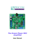
Dream Player User Manual
Version 1.2
Copyright ©2005 PRICOM Design
Table Of Contents
1
2
3
4
5
6
7
Page i
Overview .................................................................................... 1
1.1
Quick Start .......................................................................................................... 2
2.1
2.2
2.3
2.4
2.5
2.6
2.7
Power Input......................................................................................................... 3
Audio Output ...................................................................................................... 4
RS-232 Serial Port .............................................................................................. 5
RS-232 Serial Port Cable .................................................................................... 6
Trigger Input Terminal Strip............................................................................... 7
Control Output Terminal Strip.......................................................................... 10
Mounting Holes ................................................................................................ 12
3.1
3.2
3.3
3.4
3.5
3.6
3.7
3.8
Power Indicator................................................................................................. 13
PLAY Button .................................................................................................... 13
Trigger Inputs.................................................................................................... 14
Status Indicator ................................................................................................. 14
SD Card and Socket .......................................................................................... 14
Mode Switches.................................................................................................. 15
Creating WAV Files ......................................................................................... 17
Loading the SD Card ........................................................................................ 17
4.1
4.2
4.3
4.4
Updates ............................................................................................................. 18
Connect a PC to the Dream Player ................................................................... 18
Start the PRICOM Universal Uploader ............................................................ 19
Write Firmware Update .................................................................................... 20
5.1
5.2
5.3
5.4
Getting Connected ............................................................................................ 23
Reading the Dream Player Version................................................................... 25
Playing Specific Tracks .................................................................................... 25
Stopping Playback ............................................................................................ 25
6.1
6.2
6.3
6.4
6.5
6.6
The Dream Player feels ‘warm’........................................................................ 26
The sound is crackly ......................................................................................... 26
During a file, I hear some garbage or static ...................................................... 26
Help, I broke it!................................................................................................. 26
E-mail................................................................................................................ 26
Web Site............................................................................................................ 26
Connections ............................................................................... 3
Using the Dream Player .......................................................... 13
Firmware Updates ................................................................... 18
Dream Player control using the Serial Port ........................... 23
Problems & Support ................................................................ 26
Dream Player Specifications ................................................... 27
Dream Player – User Manual
List Of Figures
Figure 1 - Dream Player Components ................................................................................ 1
Figure 2 - Dream Player Quick Start .................................................................................. 2
Figure 3 - Power Connection .............................................................................................. 3
Figure 4 - Simple, Low-Cost Media Speakers.................................................................... 4
Figure 5 - Audio Output Connection .................................................................................. 4
Figure 6 - PRICOM Serial Cable........................................................................................ 5
Figure 7 – Dream Player Serial Port ................................................................................... 5
Figure 8 – Serial Cable Connected to PC ........................................................................... 5
Figure 9 – PC Serial Connection Modular Jack Pinout (P3) .............................................. 6
Figure 10 – PRICOM Serial Cable Wiring......................................................................... 6
Figure 11 – Trigger Input Terminal Strip Pinout (P4)........................................................ 7
Figure 12 - Simple Trigger Input Button Connections ....................................................... 8
Figure 13 - Isolated Trigger Input Button Connections...................................................... 8
Figure 14 - Isolated DCC Decoder Connections ................................................................ 9
Figure 15 – Control Output Terminal Strip Pinout (P6) ................................................... 10
Figure 16 - Simple Control Output LED Connections ..................................................... 11
Figure 17 - Lamp/Relay Control Output Connections...................................................... 12
Figure 18 - Dream Player Controls................................................................................... 13
Figure 19 - Mode Switch Settings .................................................................................... 15
PRICOM Design
Page ii
Section 1 - Overview
1 Overview
Congratulations on your purchase of the Dream Player. We are sure that you will enjoy
the unique combination of audio quality and features available to you. With the ability to
electronically update the software in the Dream Player, you can be sure that your
investment was a wise one. Additionally, if there are any features you can think of, or
options that you would like to see, please let us know! Hearing from real customers in the
‘real-world’ is the best way to improve any product.
The Dream Player is a high quality, solid-state playback device for audio program
material. Similar in function and quality to a good CD player, the Dream Player adds the
ability to remotely trigger one of four audio ‘tracks’ and loop them continuously. In
addition, the Dream Player also gives you the ability to control lights, motors, or other
loads when a specific ‘track’ or sound file is playing. Add to this the fact that the Dream
Player doesn’t have any moving parts, makes it the perfect audio playback device for
heavy-duty application.
Figure 1 - Dream Player Components
The Dream Player utilizes state-of-the-art FLASH memory technology to allow the
software/firmware to be updated by the customer. Simply attach a PRICOM RS-232
Serial Cable to your PC, and using our Universal Uploader you can quickly update the
FLASH Image file. As features are added or updated, you can obtain an updated FLASH
Image file from the PRICOM Web Site, and load it into your Dream Player.
Page 1
Dream Player – User Manual
Section 1 - Overview
1.1 Quick Start
To get things going quickly, you simply need to follow these steps:
1.
2.
3.
4.
5.
6.
Unpack the Dream Player
Connect the Power Input (see Section-2.1 Power Input)
Connect the Speakers (see Section-2.2 Audio Output)
Insert an SD Card with .WAV files (see Section-3.7 Making WAV Files)
Turn the Power Input On
Press the “PLAY” Button
Figure 2 - Dream Player Quick Start
Creating the WAV files for the SD card can be the trickiest part to master. If you
purchased your Dream Player complete with sounds on an SD Card, you are all set to go.
If you need to create the files for your Dream Player, please see Section-3.7 entitled
“Making WAV Files”. The process is quite easy once you get the hang of it. You can
download sample sounds from our web site www.pricom.com.
Included with your Dream Player is a sample sound CD. You can copy these files onto a
SD Card, and get a good taste of what Layout Sound can offer your pike.
You can also purchase ready-to-run Scale Magic™ sounds, available from Fantasonics
Engineering. Their web site is www.fantasonics.com
PRICOM Design
Page 2
Section 2 – Connections
2 Connections
The following section provides detailed instructions for connecting your Dream Player.
To get started quickly, all you need to do is connect the Power Input, and the Audio
Output. Then when you are ready, you can get more advanced and use the Trigger Inputs
and Control Outputs.
Figure 3 - Power Connection
2.1 Power Input
The Dream Player can accept AC or DC power inputs.
Typically a wall transformer, or wall-wart is used, but
any suitable AC or DC power supply can be used. Any
voltage from 8V to 24V AC or DC can be used, but the
higher the voltage, the warmer the Dream Player will
run. The most efficient voltage to use is 8 to 9VDC. At
this voltage, the Dream Player will draw about 200MA,
so use a power supply that can supply 200MA or more
of current. A 9VDC 300MA wall-transformer is
available at Radio Shack, Cat# 273-1767. Similar units
are available from many on-line retailers as well as All
Electronics. If you wish to power multiple Dream
Players, a single larger power supply can be used, just
allow for 200MA for each Dream Player you wish to
power. As a convenience to you, we also offer walltransformer power supplies tested and ready to run with
your Dream Player at www.pricom.com
The power source used can be shared with other
devices, but be careful as the Audio Ground will be
referenced to this power source. If you observe a
buzzing or other interference noise, it would be best to
give your Dream Player its own power supply.
To connect the power supply to the Dream Player,
please refer to Figure-1 and locate the 2-position
“Power Input” terminal strip.
If your desired power-supply comes with a connector on
the end, simply clip it off as shown to the right. Separate
the two wires and strip some insulation off to expose the
actual wires then twist them to keep the strands
together. Secure the stripped wire ends to the 2
terminals of the Power Input terminal strip. The polarity
of an AC or DC power source is not important as there
is a bridge rectifier included with the Dream Player.
Page 3
Dream Player – User Manual
Section 2 - Connections
2.2 Audio Output
The Dream Player will drive any audio amplifier or powered speakers or media speakers
as is typically used on a computer. The Dream Player can NOT directly drive a nonpowered or conventional speaker without an amplifier. If you attempt to drive a
conventional speaker with the Dream Player, no damage will occur, but the volume
obtainable with this setup is probably unacceptable. With the prices of media speakers so
low, and since they are the most popular small speakers obtainable at just about any
retailer, we chose to standardize on
Figure 4 - Simple, Low-Cost Media Speakers
them. Depending on the quality and
volume you are trying to achieve, these
speakers can be purchased for $25-$50,
or as high as $100. We have found that
many of the $35-$50 speakers sound
terrific for model railroading use, and
some of them are quite small and easy to
conceal. Choose your speakers wisely as
the best audio you can get is often times
limited by the quality of the speakers
you choose. If you are at a loss for what
speakers to get, we offer some reviews
of speakers we have purchased on-line
with some links to how you may
purchase them. Please visit
www.pricom.com
To connect the speakers to the Dream
Player, you simply plug-in the stereo plug
from the speakers into the Audio Output
jack on the Dream Player. You can insert
as many extensions as needed to
accomplish your layout wiring. These
extensions are 1/8” stereo cables, and
sometimes are sold as headphone
extension cables. Check Radio Shack, or
your favorite retailer for this cable.
Figure 5 - Audio Output Connection
Set the volume on the speakers’ pretty low to start with, and then adjust as appropriate for
your sounds and speaker setup. With the Fantasonics Engineering Scale Magic™ sounds
sampler we have provided with the dream player, always start with the speakers turned
down all the way, then gradually bring the volume up until the sound is a nice low
background level. The Scale Magic™ sounds are available as a bundled option, or always
available separately from the Fantasonics web site at www.fantasonics.com.
PRICOM Design
Page 4
Section 2 – Connections
2.3 RS-232 Serial Port
You can load software updates as well as control your Dream Player using the RS-232
port and any attached computer. Useful information is also sent out the RS-232 port
during playback such as file format, running state, etc. A simple ‘terminal’ program can
be used to control the Dream Player, or soon you will also be able to use JMRI to control
the Dream Player, check the PRICOM web site for detailed information about JMRI
support.
To connect the Dream Player to your computer, first locate the PRICOM Serial Cable
(available from www.pricom.com), or you can build one using the connector pinout
information below. First connect the modular jack end of the Serial Cable to the Dream
Player P3. Connect the other end to an available Serial Port on your computer.
Be aware that the RS232 Serial Port of the Dream Player is NOT electrically isolated
from the Audio Ground derived from the attached power supply. Attaching the Audio
Ground to your PC though the Serial Cable can introduce a bit of ‘hum’ or ‘buzzing’ in
the Audio Output. This is not harmful as long as the power input is ‘floating’, meaning
you did not ground either of the power input pins to earth ground.
Figure 6 - PRICOM Serial Cable
Figure 7 – Dream Player Serial Port
Figure 8 – Serial Cable Connected to PC
To load the firmware updates, please see Section-4 entitled “Firmware Updates”.
Page 5
Dream Player – User Manual
Section 2 - Connections
2.4 RS-232 Serial Port Cable
For your reference, we have included the pin connections for the RS232 port below. You
can purchase a pre-made cable from www.pricom.com, the dealer you bought your
Dream Player from, or you can just make your own. The following information will help
if you decide to make your own.
Figure 9 – PC Serial Connection Modular Jack Pinout (P3)
Pin
1
2
3
4
5
6
Name
N/C
Ground
TxData
RxData
Ground
N/C
Description
Not connected
Signal Ground
Transmit Data To the PC
Receive Data From the PC
Signal Ground
Not connected
If you inadvertently wire the Modular Connector backwards, no damage will be done but
the TxData and RxData leads will be reversed. If you can not get the PC to talk to the
Dream Player, check to make sure you have the Modular Plug attached to your cable the
correct way.
Figure 10 – PRICOM Serial Cable Wiring
Modular
Pin
1
2
3
4
5
6
DB-9F
Pin
5
2
3
5
Signal
Name
N/C
Ground
TxData
RxData
Ground
N/C
Description
Not Connected
Signal Ground
Transmit Data To the PC
Receive Data From the PC
Signal Ground
Not Connected
PRICOM Design
Page 6
Section 2 – Connections
2.5 Trigger Input Terminal Strip
More than simply playing a sound file, your Dream Player is capable of acting and
reacting based on input from you or the devices it is controlling. This section describes
the electrical connections for the Trigger Inputs. Section-3 entitled “Using the Dream
Player” describes the operational functions and events that are controlled by the Trigger
Inputs.
The Trigger Inputs of the Dream Player are optically isolated which means you can wire
the inputs so that they are electrically isolated from the Dream Player. Why is that
important? Because sharing a common ground between an Audio Playback system and
any other system can, and usually does, create ground loops and noises such as ‘buzz’
and ‘hum’. By isolating the Trigger Inputs, we have removed this problem for you!
As a convenience to your wiring, you may use the power supplied on the Trigger Input
Terminal Strip, but doing so will defeat the isolation offered by the Dream Player. If you
are simply wiring switches, there isn’t much chance of a ‘ground loop’ or ‘noise’, so we
give you the best of both worlds.
Figure 11 – Trigger Input Terminal Strip Pinout (P4)
Terminal
1
2
3
4
5
6
7
Name
GND
Trigger-1
Trigger-2
Trigger-3
Trigger-4
POS
5V
Description
Convenience power supply ground
Opto-Isolated Trigger #1 Input
Opto-Isolated Trigger #2 Input
Opto-Isolated Trigger #3 Input
Opto-Isolated Trigger #4 Input
Opto-Isolator Shared Power Input
Convenience power supply (5VDC)
The trigger input terminals (Trigger-1 to Trigger-4) provide connection to the low-side
(Cathode) of the LED in each opto-isolator. Current limiting resistors are built-in, so you
can simply connect any Trigger Input to GND to cause the Trigger to occur.
Terminal #6 (POS) is connected to the high-side (Anode) of all 4 opto-isolators.
Typically Terminal #6 is connected to the power source to be used to trigger the inputs.
This can be an external power source or Terminal #7 (5V), if you do not need to isolate
the Dream Player ground. The internal current limit resistors are suitable for voltages
from 5VDC up to 24VDC. If higher voltages are required please contact us to determine
suitable added current limit resistors.
Terminal #1 and Terminal #7 provide a local power source that is not isolated from the
Dream Player, but can be used to simplify wiring if just using push-buttons, relays, or
other input that doesn’t require optical isolation.
Page 7
Dream Player – User Manual
Section 2 - Connections
The following example shows how to connect switches (or relays for that matter) directly
to the Dream Player without utilizing the ground isolation features of the opto-isolators.
The convenience 5VDC power supply from the Dream Player is jumped to the optoisolator POS terminal to supply the shared LED Anodes. Each Trigger Input can then be
individually connected to the convenience GND pin though any suitable switching device
such as a push-button or relay.
Figure 12 - Simple Trigger Input Button Connections
Note: The actual function of each Trigger Input is determined by DIP Switch settings.
More detailed application information is located in Section-3 of this manual.
In the next example, we will use an external power supply to enable the opto-isolators to
completely isolate the Dream Player Ground from the controlling device. Notice that the
POS terminal is used, but not the 5V or G terminals. Opto-isolator power is supplied
from the external 4-24VDC Power Supply.
Figure 13 - Isolated Trigger Input Button Connections
PRICOM Design
Page 8
Section 2 – Connections
The switch examples shown above don’t really need the opto-isolators, so where would
you need the opto-isolators? How about connecting to a DCC Decoder!
In the next example, we will connect a Digitrax TF4 to allow the Dream Player to be
controlled directly from your DCC System. Any brand of mobile or stationary decoder
could be used, but the low-cost of the TF4 lends itself nicely to this application.
Here we have connected the 4 function outputs of the TF4 to the 4 Dream Player Trigger
Inputs. Since the DCC Decoder must be connected to the DCC System, where there is
considerable noise, some kind of isolation would really help us here. The Dream Player
opto-isolators keep the DCC system completely isolated from the Audio Ground and
remove any chance of noise entering the sound system and speakers. Note that the 5V
and the G terminals are left un-connected since the opto-isolators are being powered from
the DCC decoder lamp power lead.
Figure 14 - Isolated DCC Decoder Connections
.
Page 9
Note: The actual function of each Trigger Input is determined by DIP Switch settings.
More detailed application information is located in Section-3 of this manual
Dream Player – User Manual
Section 2 - Connections
2.6 Control Output Terminal Strip
The Dream Player is capable of controlling many types of devices and loads connected to
the Control Outputs. This section describes the electrical connections for the Control
Outputs. Section-3 entitled “Using the Dream Player” describes the options and functions
possible using the Control Outputs.
The Control Outputs of the Dream Player are not isolated in any way from the Audio
Ground of the Dream Player. Why is that important? Because sharing a common ground
between an Audio Playback system and any other system can, and usually does, create
ground loops and noises such as ‘buzz’ and ‘hum’. If grounding problems become an
issue for your application, an external relay can be used to isolate the load from the
Dream Player.
As a convenience to your wiring, you may use the power supplied on the Control Output
Terminal Strip, but doing so will draw power from the internal 5V regulated supply used
to power the Dream Player. Use this convenience power for LED’s, small relays, or
triggering another Dream Player, but if you intend to power any larger loads, please
consider an external power source for the Control Outputs.
Figure 15 – Control Output Terminal Strip Pinout (P6)
Terminal
1
2
3
4
5
6
7
Name
GND
Output-1
Output-2
Output-3
Output-4
Clamp
5V
Description
Convenience power supply ground
Control Output #1
Control Output #2
Control Output #3
Control Output #4
Common Clamp Diode Connection
Convenience power supply (5VDC)
The control output terminals (Output-1 to Output-4) provide connection to a Darlington
Transistor Array (Collector) used to Sink Power, but can not Supply Power. Each Output
is capable of sinking 400MA using the ULN2803 in the socket at U7. The Darlington
Array has its Emitters connected to the GND Terminal #1. External or Convenience
power can be used to power the load, but the reference and current ground will be using
GND Terminal #1.
Terminal #6 (Clamp) is connected to the Darlington Array protection diodes (Cathode)
for all 4 outputs. If you are driving an inductive load such as a relay, the Clamp terminal
should be connected to the power source being used for the load. This Clamp Terminal
will prevent the back-lash of the relay from destroying the Darlington Array. If simply
driving LED’s this terminal can be left un-connected.
PRICOM Design
Page 10
Section 2 – Connections
Terminal #7 provides a local power source that is not isolated from the Dream Player, but
can be used to simplify wiring if just powering LED’s or other small loads. Power used
from this terminal can cause the on-board voltage regulator to become hot under load.
The following example shows a simple way to connect status LED’s to the Dream Player
using the convenience 5VDC power supply. The LED’s will require current-limiting
resistors since each Control Output can sink 400MA and would burn-out the LED’s.
Since the LED’s do not present an inductive load, the Clamp terminal has been left unconnected.
Figure 16 - Simple Control Output LED Connections
Note: The function of each Control Output is determined by DIP Switch settings.
More detailed application information is located in Section-3 of this manual
The Dream Player can also be used to drive conventional DC powered lamps or DC
powered relays. Using external relays allow much higher power to be controlled, or even
AC Line voltage. The possibilities are endless, but the next example shows how to
connect external lamps or relays using an external power source.
The external power source is used for this example so that not too much power is
consumed from the Dream Player’s on-board 5VDC power supply regulator. If the relays
are high-efficiency and can be powered from 5VDC, then the on-board 5VDC power
source could be used. In the following example, we are using an external power source.
Page 11
Dream Player – User Manual
Section 2 - Connections
Figure 17 - Lamp/Relay Control Output Connections
The common lamp/relay connection must be to the Positive terminal of the power supply,
and also is connected to the Clamp terminal to utilize the Dream Player’s built-in
protection diodes. The external power supply Negative terminal is connected to the GND
Control Output terminal. This arrangement causes the positive voltage to flow though the
lamp/relay, into the Control Output terminal, and back out the G Control terminal, and
complete the circuit at the power supply negative terminal.
Because the Dream Player uses a Darlington Transistor array for the output control
switching element, AC power can not be used, only DC is possible.
2.7 Mounting Holes
The Dream Player can be mounted to any non-conducting surface using the supplied
mounting holes. Since there are parts protruding from the bottom of the Dream Player,
using some form of stand-off would be advisable to keep from breaking anything. The
mounting holes are electrically isolated, so using steel screws is fine, but be careful not to
over tighten them.
PRICOM Design
Page 12
Section 3 – Using the Dream Player
3 Using the Dream Player
The following pages describe the configuration and operation of the Dream Player. Many
possible configurations are possible, but you can keep it as simple as you wish.
Figure 18 - Dream Player Controls
3.1 Power Indicator
Quite simply, this LED will be lit whenever there is power supplied to the Power Input
terminals. This LED can be easily removed if your installation needs complete darkness.
3.2 PLAY Button
To play the first Track on the SD card at any time, you can simply hit the PLAY button.
If you press the PLAY button when the Dream Player is already playing, the sound will
fade out and stop.
Page 13
Dream Player – User Manual
Section 3 – Using the Dream Player
3.3 Trigger Inputs
These inputs are the way to control the activities of the Dream player. When the Dream
Player is idle, any trigger input will cause that track to play. Trigger #1 will start File #1,
etc. While the Dream Player is playing a track, any trigger input will cause the current
track to fade out, and the new file to begin once the fade is complete. If you trigger the
input corresponding with the currently playing file, then the current track will fade out
and the player will stop.
Details of how to connect to the trigger inputs is explained in Section 2.5 entitled
“Trigger Input Terminal Strip”.
3.4 Status Indicator
This LED will be lit when the Dream Player is currently playing an Audio Track or busy
reading the SD Card. If there are troubles loading the SD Card, or a bad WAV file was
encountered this indicator will flash.
When you insert an SD Card into the SD Card Socket, you will notice that the Status
Indicator will go on for a few seconds. This shows that the Dream Player is reading the
SD Card to detect the files loaded. Once this initialization process is complete, the Status
Indicator will turn off. If you push the PLAY button while the SD Card is initializing, the
Dream Player will begin playing the first audio track once the initialization is complete.
3.5 SD Card and Socket
Audio content is loaded onto an SD FLASH Card, and then inserted into the SD Card
Socket. The socket has a spring eject feature that will eject the SD Card when you press
the card into the socket. The SD Card can be inserted or removed at any time, even with
power applied to the Dream Player. The SD Card power is switched on and off by the
insertion or removal of the SD Card. In fact, you can eject the SD Card while the Dream
Player is playing audio and no damage will be done!
PRICOM Design
Page 14
Section 3 – Using the Dream Player
3.6 Mode Switches
The Dream Player has many options available for the Trigger Inputs, Control Outputs,
and other functions. Each of these options is set using the Mode DIP Switches.
Figure 19 - Mode Switch Settings
Switch 1 – Loop Mode
The selected audio track will play continuously over and over until
ON
another Trigger Input is detected or the PLAY button is pressed
OFF The audio tracks will play once only and stop when the end is reached
Switch 2 – Random Mode
Trigger #1 or Trigger #2 will cause a random track to be selected and
ON
played. The random track will play once or loop forever depending on the
setting of Switch 1 – Loop Mode
OFF Random track selection is not enabled
Note: When Random Mode and Loop Mode are both ON, Trigger #1 will pick a new
random track with each playback loop. Trigger #2 will pick a random track and
continue to loop that single random track.
Switch 3 – Loop While Trigger
The selected audio track will continue to loop and play as long as the
ON
respective trigger input is present. Once the trigger is removed, the current
track is played to completion then the Dream Player will stop
OFF Loop while trigger is not enabled
Note: Loop While Trigger can also be combined with the Random Play Mode to
cause random tracks to be played as long as the Trigger is present.
Page 15
Dream Player – User Manual
Section 3 – Using the Dream Player
Switch 4 – Spare
ON
Not used yet
OFF Not used yet
Switch 5 & Switch 6 – Control Outputs
This mode selection is not used yet
At the END of each track, the respective Control Output will
momentarily go active or pulse
At the BEGINNING of each track, the respective Control Output will
momentarily go active or pulse
During PLAY of each track, the respective Control Output will
constantly be held active
Switch 7 – Spare
ON
Not used yet
OFF Not used yet
Switch 8 – Auto Start
When power is applied to the Dream Player, playback of Track #1 will
ON
automatically begin playing after about 2 seconds
OFF Playback will NOT automatically start at power-on
All switch modes can be combined in any manner. For example, a useful setup would be
combining Auto Start Mode, Random Mode, and Loop Mode. This would cause the
Dream Player to start playing a random track after power-up, when the track ends, pick
another random track and play. This process would continue until a trigger input is
detected or the PLAY button is pressed.
PRICOM Design
Page 16
Section 3 – Using the Dream Player
3.7 Creating WAV Files
Any suitable sound editor can be used to create WAV files. The Dream Player will play
Mono or Stereo, 8-bit or 16-bit samples, and from 16KHz up to 44.1KHz sample rate.
For the best sound quality and to utilize the impressive sound capabilities of the Dream
Player, we suggest using Stereo – 16bit – 44.1KHz for your wav files. (This is the same
format used for CD Players and is quite standard.)
Note: The Dream Player can NOT play MP3 files or other non-wav files.
Please visit the PRICOM Design web site (www.pricom.com), as we are planning on
writing some general application notes for creating sounds and wav files.
The Dream Player will only play wav files whose file name starts with ‘1’, ‘2’, ‘3’, or ‘4’.
These numbers indicate to the Dream Player what ‘track’ they are, and which Trigger
Input they are to be associated with. You can name your files anything you want, but the
Dream Player can only play them if this numbering rule is obeyed. For your convenience,
you can name the files something sensible like “Mountain Day.wav” on your computer,
and then rename the file once it is on the SD Card. A good file name is something like
“1-Mountain Day.wav” which would be treated as Track-1 and can be started with
Trigger Input #1 on the Dream Player.
3.8 Loading the SD Card
In order for the Dream Player to receive its files, they must be copied onto an SD Card.
Any standard SD Card reader attached to any computer can be used. The Dream Player
will accept any brand of SD Card, in any capacity from 64MB up to 1GB. We have not
tested the 2GB cards, but they should also work.
Simply copy your wav files onto the root folder of the SD Card. The Dream Player will
not look in any sub-folders or sub-directories for its files, only the root folder. After you
copy files onto the SD Card, any file can be renamed at any time. This is a handy way to
change a track from Trigger #1 to Trigger #2. However, if you delete ANY file off the
SD Card for any reason, ALL files must be deleted and re-copied onto the SD Card. This
is because the Dream Player can not read a file that is scattered or fragmented all over the
SD Card. We hope to correct this issue in a future software update.
Important: If you delete ANY file off the SD Card for any reason, ALL files must be
deleted and re-copied onto the SD Card. This is because the Dream Player can not read a
file that is scattered or fragmented all over the SD Card.
The symptom of this problem is hearing a noisy “spurt” during a track playback. You
could also hear portions of a different file in the middle of the current file playback. If
you observe these symptoms, delete ALL the files off the SD Card, and re-copy them.
Page 17
Dream Player – User Manual
Section 4 – Firmware Updates
4 Firmware Updates
The PRICOM Dream Player uses FLASH memory to enable in-field upgradeability by
the customer. All that is required is a PC with a Serial Port (RS-232). The Dream Player
will look for an attached PC every time it Powers-On. The “BOOT CODE” is stored in
Protected FLASH and is not erasable. That means that even if the PC were to crash, or
there was a problem loading a Firmware Image Update, the process can be started over
without risking anything.
4.1 Updates
Check on our web site www.pricom.com for updates to the Dream Player Firmware. We
suggest putting all your downloaded updates and Firmware into a folder called
“C:\PRICOM”, but you can put it anywhere that makes sense for you. Once you have
downloaded a Firmware Update, you will need to write the Firmware to the Dream
Player using the following procedure.
If you would like to be notified of any updates, please send us an email to
[email protected] with the model and serial number of your unit, and we will be happy
to notify you when there is a new firmware file available.
You will need the PRICOM Universal Uploader, available from our www.pricom.com
web site. You may also need the Microsoft .NET Framework installation. This is a rather
large download from Microsoft so we have a copy in the Downloads area of our web site.
You can also obtain the .NET Framework using Windows Update, select ‘Custom’ and
click on ‘Optional Updates’.
4.2 Connect a PC to the Dream Player
Connect the Serial Cable as described in Section-2 Connections. You will also need a
power source for the Dream Player. Once the Serial cable is connected, run the PRICOM
Universal Uploader PC Software.
The screen shots that follow are taken from the Universal Uploader Version 1.1.
PRICOM Design
Page 18
Section 4 – Firmware Updates
4.3 Start the PRICOM Universal Uploader
Start the Universal Uploader program in Windows by clicking:
“Start
All Programs
PRICOM Design
Universal Uploader”
You should see a screen like the one shown below:
You can easily change the Serial Port used to communicate with the Dream Player by
clicking on the “Port Setup” menu item. If you have never run the Universal Uploader,
the Port Configuration screen will load immediately when you start the program.
Of course if you set the port to “No Serial Port”, you can’t load the firmware into the
Dream Player! Please let us know if you have any issues with the Universal Uploader.
Page 19
Dream Player – User Manual
Section 4 – Firmware Updates
4.4 Write Firmware Update
To update the Firmware, click on the “Write Firmware” button on the main screen. You
will receive a confirmation box to make sure you want to write the Firmware to the
Dream Player. Then you will see a typical Windows File Open dialog box such as this:
Locate and select the appropriate Firmware file you downloaded, the current version as of
this writing is “DreamPlayer_v1_2.pdi” (Version 1.2). Depending on where you saved
this file on your system, you may need to use the “Look In” menu-bar at the top of the
screen to find the necessary firmware file. Once you have selected the Firmware file,
click the “Open” button. A message box will show the date and time the Firmware Image
was created, such as this:
Click “OK” to open the selected firmware image file.
PRICOM Design
Page 20
Section 4 – Firmware Updates
The Universal Uploader Software will send a message to the screen saying “RESET THE
TARGET HARDWARE NOW”. This can be accomplished by unplugging the power
from the Dream Player and then plugging it back in. This causes a full hardware reset of
the Dream Player.
If for any reason, you want to stop this Firmware Update, just click on the “Cancel
Firmware Update” button that now appears.
Once the Dream Player is powered back up, you will see a progress box showing the
status of the Firmware upgrade:
Page 21
Dream Player – User Manual
Section 4 – Firmware Updates
Once the Firmware upgrade is complete, the Dream Player will restart. When it does, you
should see a “Booter…” message such as the one shown below on your Universal
Uploader screen. The Dream Player may not send a “Greetings…” message like the one
shown below, but if it does, it will say “Dream Player” instead of “DCC Tester”.
Note: Firmware 1.2 does not send a “Greetings…” message, this will be added in the
next release of firmware.
Notice that the “BadRX” display on the bottom of the screen shows ‘0’. This is a good
indication that all the data was sent to the Dream Player without errors. If for some
reason you see a number other than ‘0’ in this box, it would be a good idea to check your
connections, exit the Universal Uploader, and re-start the Universal Uploader again.
If the Firmware Update process is interrupted in any way, power outage, or other ‘issue’,
it is advisable to re-write the Firmware Image again.
It’s a good idea to keep your old firmware versions in case you want to go-back to an
older version. We will keep the prior-versions on our web site as well so that if you
encounter problems with a new version, you can always put it back to what you had
before.
Now that you have updated the firmware, you can disconnect the Serial Cable and go do
some listening…
PRICOM Design
Page 22
Section 5 – Serial Port Control
5 Dream Player control using the Serial Port
This section outlines how to control the Dream Player using the RS-232 Serial Port. We
will walk through how to setup and use HyperTerminal on a PC to talk to the Dream
Player. HyperTerminal is a “Terminal Emulation” program that comes with Windows.
You can use any such program to use the Serial Port features of the Dream Player, but
since Windows comes with HyperTerminal for free, we have used it in the examples. If
you are on a platform other than Windows, the information is basically the same, but you
will have to translate the commands to the Terminal Emulation program you are using.
Be aware that the RS232 Serial Port of the Dream Player is NOT electrically isolated
from the Audio Ground. Connecting to the RS-232 Serial Port can cause a ground loop,
hum, or buzzing from the speakers. If you experience this problem, make sure your
computer and the Dream Player are plugged into the same electrical circuit possibly
reducing the noise.
5.1 Getting Connected
If using Windows XP click the following menus to start HyperTerminal:
Start All Programs Accessories Communications HyperTerminal
Give the connection a name. The name is not important at all, but this allows you to save
the settings for future sessions of HyperTerminal. In our example, we have called our
new connection “Dream Player”. You can also select a handy-dandy icon to represent the
new connection, or just use the default ‘Telephone’. Then Click OK to create the
connection and bring you to the Connection screen shown below:
Page 23
Dream Player – User Manual
Section 5 – Serial Port Control
Select the appropriate value under “Connect
using:” to match the Serial Port in your PC that is
connected to the Dream Player.
For our example, we are using COM2 on our PC.
Click the pull-down menu to select the proper port
and then click “OK”. This will bring up the Port
Settings screen shown below:
Using the Connection Properties menu set the
values as shown here to the right. The Dream
Player uses 9600 for the “Bits per second:” (baud
rate) setting.
Set the Data Bits, Parity, and Stop Bits as shown
to the right.
The flow control selection is important as the
Dream Player only uses the ‘data’ wires or leads
to connect to the PC. Be sure to set the flow
control to “None”. When finished, click “OK” to
open the Serial Port and display the
HyperTerminal screen.
Once the port is configured,
and the HyperTerminal screen
is displayed, power-on the
Dream Player. You should see
a “Greetings…” message
similar to the one shown here.
If you don’t get anything on the
screen, or if you get some
‘garbage’ characters, check the
connections and the port
settings, especially the “bits per
second” (baud rate).
PRICOM Design
Page 24
Section 5 – Serial Port Control
5.2 Reading the Dream Player Version
The ‘V’ (Version) command causes the current firmware version from the Dream Player
to be sent out the Serial Port. Pressing the ‘V’ key on the PC keyboard will display the
current version from the Dream Player. This is shown in the above screen at the bottom.
5.3 Playing Specific Tracks
To play a specific track, press the ‘1’, ‘2’, ‘3’, or ‘4’ keys on the PC keyboard. This
simulates the same function as the Trigger Inputs. All Loop, Random, and Control Output
functions will operate normally.
5.4 Stopping Playback
To fade-out and stop playback, press the “S” key on the PC keyboard.
Page 25
Dream Player – User Manual
Section 6 – Problems & Support
6 Problems & Support
Our goal is a product that is robust and trouble-free for you, however in the real-world,
problems unfortunately do arise. Below is some guidance to solving some of the
problems we encountered during the testing of the Dream Player.
6.1 The Dream Player feels ‘warm’
This is normal. It shouldn’t be hot enough to burn or melt plastic, but you will feel a
warm spot around the CPU labeled “U1” and also the voltage regulator labeled “VR1”.
The CPU just gets a little hot, nothing to worry about, even though it does seem a little
strange. The voltage regulator will get progressively hotter with increased Power Input
voltage. The best solution is to use 8VDC up to 9VDC as the power source.
6.2 The sound is crackly
The Dream Player can put out a substantial amount of voltage on the Audio Output jack,
but can not drive un-powered speakers directly. Be sure your speakers are powered,
which means they have a speaker amplifier built in. The typical indicator of this is a
volume control, power switch, and power cord on the speakers. If you attempt to use unpowered speakers, the Dream Player will be forced to drive speakers directly, which it
was not intended to do.
6.3 During a file, I hear some garbage or static
If you delete ANY file off the SD Card for any reason, ALL files must be deleted and recopied onto the SD Card. This is because the Dream Player can not read a file that is
scattered or fragmented all over the SD Card. Please see Section 3.8 “Loading the SD
Card”. The symptom of this problem is hearing a noisy “spurt” during a track playback.
You could also hear portions of a different file in the middle of the current file playback.
If you observe these symptoms, delete ALL the files off the SD Card, and re-copy them.
6.4 Help, I broke it!
If you are not happy, then we are not happy! If you have a mishap with your Dream
Player, please let us know. We would be happy to repair it for you. Depending on the
amount of damage, we can repair it quite economically.
6.5 E-mail
If you are experiencing trouble with your Dream Player, please let us know. We are here
to help you, and want your experience to be creative and fun. If you need help of any
kind, please contact us via e-mail. The support e-mail address is [email protected].
6.6 Web Site
The PRICOM web site is where we will post any upgrades, updates, and improvements.
Please be sure to check for Hardware and Software updates. www.pricom.com
PRICOM Design
Page 26
7 Dream Player Specifications
Power Input:
7-24V AC or DC
Connection using 2 position terminal strip
Current consumption approximately 200mA
Trigger Input:
4 Inputs for Switches or Contact Closures
Connection using 7 position terminal strip
Optically isolated with built-in current limit resistors
Trigger Output:
4 Outputs for relays, lamps, LEDs, other player trigger inputs
Connection using 7 position terminal strip
Pulls to GND. Outputs rated for 200mA each
Audio Output:
Line Level Analog Audio Output
Connection using 3.5mm (1/8”) Stereo Jack
Allows direct connection of amplified ‘media speakers’
Audio Formats:
8bit or 16bit, mono or stereo
Sample Rates:
16KHz, 22.05KHz, 24KHz, 32KHz, 44.1KHz
Output Level:
3V Peak-To-Peak Maximum
Storage Device:
SD or MMC FLASH Card 64MB up to 2GB
64MB card holds 6 minutes of Stereo 44.1KHz 16bit audio
512MB card holds 48 minutes of Stereo 44.1KHz 16bit audio
1GB card holds 94 minutes of Stereo 44.1KHz 16bit audio
2GB card holds 188 minutes of Stereo 44.1KHz 16bit audio
Storage Format:
FAT-12 or FAT16 formatted cards (standard)
File Format:
Standard WAV files placed in the root folder of the card
Page 27
Dream Player – User Manual
Dream Player User Manual
Version 1.2
Copyright ©2005 PRICOM Design


