1
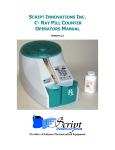
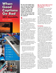
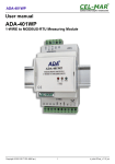
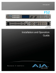
FBE-204LT Bunch-by-bunch Feedback Front/Back-End Technical User Manual Author: Dmitry Teytelman July 4, 2011 Revision: 1.1 Information in this document is subject to change without notice. Copyright © Dimtel, Inc., 2010-2011. All rights reserved. Dimtel, Inc. 2059 Camden Avenue, Suite 136 San Jose, CA 95124 Phone: +1 650 862 8147 Fax: +1 603 907 0210 www.dimtel.com CONTENTS Contents 1 Regulatory Compliance Information 2 Introduction 2.1 Delivery Checklist . . . . . . . . 2.2 System Overview . . . . . . . . 2.3 Front Panel Features . . . . . . 2.4 Rear Panel Features . . . . . . 2.5 Cooling Fan Filter Maintenance 2.6 Getting Started . . . . . . . . . . . . . . . . . . . . . 2 . . . . . . . . . . . . . . . . . . . . . . . . . . . . . . . . . . . . . . . . . . . . . . . . . . . . . . . . . . . . . . . . . . . . . . . . . . . . . . . . . . . . . . . . . . 3 3 3 5 7 8 9 3 Setup 10 3.1 Front-end . . . . . . . . . . . . . . . . . . . . . . . . . . . . . 10 3.2 Back-end . . . . . . . . . . . . . . . . . . . . . . . . . . . . . . 11 4 Specifications 12 5 Warranty and Support 14 5.1 Warranty . . . . . . . . . . . . . . . . . . . . . . . . . . . . . 14 5.2 Support . . . . . . . . . . . . . . . . . . . . . . . . . . . . . . 14 6 Glossary 15 1 of 15 Regulatory Compliance Information 1 Regulatory Compliance Information This equipment requires a ground connection provided by the power source. The exposed metal parts of the unit are connected to the power ground to protect against electrical shock. Always use an outlet with properly connected protective ground. FBE-204LT was designed and tested to operate safely under the following environmental conditions: indoor use; altitude to 2000 meters; temperatures from 5 to 40 ◦ C; maximum relative humidity 80% for temperature 31 ◦ C, decreasing linearly to 50% @ 40 ◦ C; pollution category II; overvoltage category II; mains supply variations of ±10% of nominal. FBE-204LT contains no user serviceable parts inside. Do not operate with the cover removed. Refer to qualified personnel for service. NOTE: This equipment has been tested and found to comply with the limits for a Class A digital device, pursuant to Part 15 of the FCC Rules. These limits are designed to provide reasonable protection against harmful interference when the equipment is operated in a commercial environment. This equipment generates, uses, and can radiate radio frequency energy and, if not installed and used in accordance with the instruction manual, may cause harmful interference to radio communications. Operation of this equipment in a residential area is likely to cause harmful interference in which case the user will be required to correct the interference at his own expense. NOTE: This Class A digital apparatus complies with Canadian ICES-003. Cet appareil numérique de la classe A est conforme à la norme NMB-003 du Canada. 2 of 15 Introduction 2 Introduction 2.1 1. 2. 3. 4. 2.2 Delivery Checklist FBE-204LT chassis; AC power cord; GPIO 68-pin male to 68-pin male cable; User manual. System Overview Front-end section Two cycle comb filter From BPM hybrid Σ Variable attenuator Amplifier Mixer Σ To the ADC × Phase shifter 7 × frf Step recovery diode frequency multiplier frf Low-pass filter Front-end channel (×3) 7× multiplier Digital control interface 5× multiplier Step recovery diode frequency multiplier iGp GPIO 5 × frf From the DAC To the power amplifier × Mixer Variable attenuator Amplifier Bandpass filter Back-end section Figure 1: Bunch-by-bunch feedback front/back-end block diagram The FBE-204LT RF signal processor incorporates front-end and backend electronics for a complete bunch-by-bunch feedback system in a storage ring. The unit is equipped with three identical front-end channels — for processing horizontal, vertical, and longitudinal signals. Front-end channels are designed for converting the beam position monitor (BPM) output to the baseband signal which can be directly digitized by the iGp/iGp12. Each channel operates at 1428 MHz and uses a 2-cycle comb filter to produce a 3 of 15 2.2 System Overview detected pulse of 1.3 ns. The back-end channel upconverts the baseband kick signal to 1020 MHz carrier for driving the power amplifier and the kicker. The FBE-204LT interfaces to the iGp/iGp12 digital general-purpose input/output (GPIO) port for control and monitoring. Control channels include frontand back-end attenuators and phase shifters and fan speed. Through the GPIO port, iGp/iGp12 is also able to read out the unique FBE-204LT serial number and to monitor the internal temperature. 4 of 15 2.3 Front Panel Features 2.3 Front Panel Features 1 2 3 4 5 6 7 8 9 10 11 12 13 Figure 2: Front panel features 1) Power switch This on-off lighted switch turns FBE-204LT on and off. 2) Horizontal front-end output Baseband output to iGp/iGp12. 3) Horizontal front-end input This input receives the beam signal from the BPM difference hybrid network. Maximum continuous wave (CW) level is 33 dBm. For typical beam signal this limitation can be expressed as maximum swing of 14 V. 4) Vertical front-end output Baseband output to iGp/iGp12. 5) Vertical front-end input This input receives the beam signal from the BPM difference hybrid network. Maximum CW level is 33 dBm. For typical beam signal this limitation can be expressed as maximum swing of 14 V. 6) Longitudinal front-end output Baseband output to iGp/iGp12. 7) Longitudinal front-end input This input receives the beam signal from the BPM combiner network. Maximum CW level is 33 dBm. For typical beam signal this limitation can be expressed as maximum swing of 14 V. 8–10) Reference outputs Master oscillator outputs to baseband processors (iGp/iGp12). These outputs are 7 dB below the reference input level, nominally at −4 dBm. 5 of 15 2.3 Front Panel Features 11) Reference input Master oscillator reference. This reference drives front and back-end local oscillators, as well as the outputs to iGp/iGp12. Nominal input level is 3 dBm. 12) Back-end input This input should be driven by one of iGp/iGp12 high-speed digitalto-analog converter (DAC) outputs. Nominal swing expected at this input is ±250 mV. For iGp12 use a 4 dB attenuator. 7) Back-end output Output to the power amplifier. At 0 dB back-end attenuation and full 250 mV baseband drive the output level is 4 dBm. 6 of 15 2.4 Rear Panel Features 2.4 Rear Panel Features 1 2 3 Figure 3: Rear panel features 1) Voltage selection switch Slide switch for selecting appropriate mains voltage: 115 or 230 V. 2) Power entry socket IEC-320 power input socket. Always use an outlet with properly connected protective ground. 3) iGp/iGp12 interface This 68-pin connector must be attached to the iGp/iGp12 for proper operation of the control elements within FBE204LT. 7 of 15 2.5 Cooling Fan Filter Maintenance 2.5 Cooling Fan Filter Maintenance Figure 4: Fan filter mounted using four thumb nuts Cooling fan is located on the left side of the FBE-204LT. An stainless-steel mesh filter is mounted externally with four thumb nuts. WARNING: Fan filter protects the system from contamination. Operating the unit without the filter can lead to overheating as well as to premature failure of the cooling fans. WARNING: Before performing any work on the fan filter, power down the system and unplug the AC power cord. Fan blades are exposed when the filter is removed. The filter should be periodically serviced to maintain adequate air flow. Vacuuming, washing or replacement are the acceptable maintenance options. Replacement filter is manufactured by Qualtek Electronics Corporation, part number 06325-M. In order to remove the filter, undo the four thumb nuts. If filter servicing involves washing, make sure the filter is completely dry before reinstallation. To reinstall, orient the filter so that the mesh corrugations are vertical and slide it onto the mounting studs. Reinstall and hand tighten the thumb screws. 8 of 15 2.6 Getting Started 2.6 Getting Started In this section we will present a quick step-by-step guide to get your new RF front/back-end processor running in a minimal (single-channel) configuration. WARNING: Before connecting power to the unit make sure the voltage selection switch (Fig. 3, item 1) is in the correct position (115 or 230 V). WARNING: Signals beyond +33 dBm CW or 14 V peak can permanently damage the front-end input circuitry! Before connecting to FBE-204LT, measure BPM signals using a high-speed oscilloscope at maximum bunch currents to determine the necessary input attenuation level. 1. Configure voltage selection switch (Fig. 3, item 1). Mains supply requirements for the FBE-204LT are listed in Table 4; 2. Connect radio frequency (RF) clock at 3 dBm nominal level (Fig. 2, item 5); 3. Connect the reference output (Fig. 2, item 8) to the CLK input of the iGp/iGp12; 4. Terminate unused reference outputs with wideband 50 Ω SMA terminators; 5. Connect the front-end input (Fig. 2, item 3, 5, or 7) to the beam signal at the appropriate level; 6. Connect the front-end output (Fig. 2, item 2, 4, or 6) to the IN+ or IN- of the iGp/iGp12. Terminate the unused iGp/iGp12 input with a wideband 50 Ω SMA terminator; 7. Connect the back-end input (Fig. 2, item 6) to the OUT+ or OUTof the iGp/iGp12. Terminate the unused iGp/iGp12 output with a wideband 50 Ω SMA terminator. When using iGp12, place a 4 dB attenuator between the DAC output and the back-end input; 8. Connect the back-end output (Fig. 2, item 7) to the power amplifier input; 9. Using the supplied 68-pin GPIO cable connect the iGp/iGp12 interface (Fig. 3, item 3) to the GPIO connector on the iGp/iGp12; 9 of 15 Setup 10. Push the power button (Fig 2, item 1) to turn on the system; At this point your system is ready for use in beam diagnostics and feedback. The system must be appropriately phased and timed to the beam. This ensures proper phase detection in the front-end and correct sampling of the detected signal as well as the correct phase of the kick signal and its timing relative to the bunch arrival in the kicker. 3 Setup As mentioned in Subsection 2.6, the FBE-204LT must be properly phased and timed to the beam. In this section several possible methods for achieving proper timing and phasing will be described. Let us start with the front-end setup. WARNING: The FBE-204LT must be operated for at least two hours in the installation environment to achieve thermal equilibrium. Do not perform phase-sensitive front- and back-end adjustments before the equilibrium has been achieved. 3.1 Front-end WARNING: Front-end circuitry is sensitive to peak and average signal levels. Absolute maximum input level is +33 dBm CW or 14 V peak. However within these ranges internal amplifier damage is possible if the front-end attenuator is set too low for the input signal level! Before changing per bunch currents set the front-end attenuator to nominal attenuation at that bunch current. In order to time the front-end to the beam, a single-bunch filling pattern should be used. With a single bunch filled, connect the front-end output to a scope and adjust front-end phase for amplitude detection, producing a large pulse in the baseband signal. Next, connect the signal to the iGp/iGp12 input and adjust the timing in 100 ps steps (10 units of 10 ps delay line) to produce maximum displacement in the mean offset of one bunch. This operation results in somewhat coarse front-end timing. For more precise adjustment one can use sweep.sh script supplied with iGp/iGp12. 10 of 15 3.2 Back-end Once the front-end is timed, adjust the front-end phase for amplitude detection in the horizontal and vertical channels and for phase detection in the longitudinal channel. 3.2 Back-end Back-end timing consists of two parts: phasing the back-end local oscillator to produce maximum kick, and adjusting kick envelope timing to line up the single-bunch kick with the beam. In the first step, configure the iGp/iGp12 to generate sinewave drive at the synchrotron frequency using the turn-by-turn option of the drive generator. At this point all bunches should be driven. Next, adjust back-end phase to produce maximum longitudinal excitation, as measured by the iGp/iGp12 or by an external instrument. Drive amplitude might need to be reduced to precisely find the optimal phase. At this point we need to determine which bunch in the iGp/iGp12 processing is lined up with the beam. To do so, bisection is typically used. Initially our bunch drive pattern might look like 1:64. Select the first half of the ring using 1:32. If the beam is still excited one of the first 32 bunches in iGp/iGp12 processing coincides with the beam in the kicker. Continue the bisection until one bunch is identified. At this point one can adjust the output (one-turn) delay so that the excited bunch number agrees with the bunch number seen in the front-end. Once such agreement is reached the back-end can be considered coarsely timed. For finer timing the iGp/iGp12 output timing must be adjusted in sub-RF-period steps to maximize the beam response. 11 of 15 Specifications 4 Specifications Table 1: General specifications Parameter Operating frequency RF input level Reference output level Temperature sensing resolution Fan speed control range Unique ID Definition 204 MHz 3 ± 1 dBm -7 dB relative to the input 0.0625 ◦ C 1600–4100 RPM Provided by Maxim DS1822 device Table 2: Front-end specifications Parameter Detection frequency Maximum operating input level Absolute maximum input level Attenuation range Output level at 1 dB compression 3 dB bandwidth Baseband pulse width Phase shifter range Phase shifter resolution 12 of 15 Definition 1428 MHz 9.3 V peak 14 V peak 0–31.5 dB +5 dBm 600MHz 1.5 ns > 360 degrees < 0.2 degrees/step Specifications Table 3: Back-end specifications Parameter Modulation frequency Input level Attenuation range Maximum output level (DC input of 250 mV, 3 dBm reference) Output filter Output bandwidth Phase shifter range Phase shifter resolution Definition 1020 MHz ±250 mV 0–31.5 dB 4 dBm 5th order Bessel band-pass 180 MHz > 360 degrees < 0.2 degrees/step Table 4: Input Power Requirements Parameter Input voltage Input current Frequency Voltage selection Low voltage range High voltage range Definition 115/230 VAC 2/1 A 60/50 Hz Switch 104–126 V 207–253 V 13 of 15 Warranty and Support 5 Warranty and Support 5.1 Warranty Dimtel Inc. warranties this product for a period of one year from the date of shipment against defective workmanship or materials. This warranty excludes any defects, failures or damage caused by improper use or inadequate maintenance, installation or repair performed by Customer or a third party not authorized by Dimtel, Inc. Warrantied goods will be either repaired or replaced at the discretion of Dimtel, Inc. The above warranties are exclusive and no other warranty, whether written or oral, is expressed or implied. 5.2 Support Dimtel Inc. will provide technical support for the product free of charge for a period of one year from the date of shipment. Such support is defined to include: Gain partitioning; System interconnection issues; iGp/iGp12 interface support. Free of charge technical support specifically excludes: Commissioning with beam; Feedback algorithm development and testing; Beam dynamics characterization; Operational support related to dynamic system operation. 14 of 15 Glossary 6 Glossary Glossary beam position monitor (BPM) An RF structure that couples to the beam in the accelerator. The output signal of such a structure allows measurement of the transverse or the longitudinal beam position. 3, 5, 9 continuous wave (CW) A signal of constant amplitude and frequency. 5, 9, 10 digital-to-analog converter (DAC) A hardware device to convert a sequence of digital codes to corresponding analog voltages or currents. 6 general-purpose input/output (GPIO) A 32-bit wide digital input/output port of the iGp/iGp12. 3, 9 radio frequency (RF) In the accelerator context, a constant frequency constant amplitude signal derived from or phase locked to the storage ring master oscillator. 9, 12 15 of 15