1
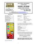
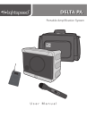
USER'S MANUAL
AM TRANMITTER Model GI-100/1000
REVISION X6
COPYRIGHT 2006, 2008, 2009 BY WAYNE MILLER
ALL RIGHTS RESERVED
The Model GI-100/1000 is a professional quality, low distortion AM
transmitter unit that is designed for continuous outdoor use. It is FCC
certified to operate in the standard AM broadcast band and can be operated
unlicensed in accordance with Part 15 of the FCC code. Made in USA.
TABLE OF CONTENTS
INSTALLATION OVERVIEW
3
SAFETY INSTRUCTIONS
4
SECTION 1 GENERAL INFORMATION
Scope
Purpose of equipment
FCC Licensing Data
Description of Unit
Specifications
Equipment Supplied
Equipment Required but not Supplied
Tools and Test Equipment Required
5
5
5
5
5
6
6
7
7
SECTION 2 INSTALLATION AND OPERATION
8
SECTION 3 THEORY OF OPERATION
Introduction
Frequency Selection
Crystal Reference
RF Oscillator
Digital Controller
Output Drivers
Input Connector
Power Filtering
Voltage Regulators
AGC and Audio Amplifiers
Modulator
RF Amplifier
Antenna Interface
Power Monitor
15
15
15
16
16
16
16
16
17
17
17
17
17
18
18
SECTION 4 TROUBLESHOOTING
19
2
COPYRIGHT 2006, 2008, 2009 BY WAYNE MILLER, ALL RIGHTS RESERVED
INSTALLATION OVERVIEW
NOTE: THIS IS A PROFESSIONAL-GRADE AM TRANSMITTER.
TO ACHIEVE ITS FULL PERFORMANCE POTENTIAL, IT MUST BE
PROPERLY INSTALLED. PLEASE READ AND FAMILIARIZE
YOURSELF WITH ALL ASPECTS OF THE INSTALLATION BEFORE
BEGINNING.
READ Safety Instructions (page 4)
CHOOSE a location for installation (page 8)
GATHER required tools and equipment (page 8)
INSTALL transmitter unit (page 9)
GROUND transmitter unit (page 9)
INSTALL antenna (page 10)
ATTACH cable to power source (page 10)
ATTACH cable to audio source (page 10)
ATTACH cable to transmitter unit (page 11)
CHOOSE transmit frequency (page 12)
TUNE transmitter unit (page 13)
SECURE transmitter unit (page 14)
OPERATE (page 14)
!! CAUTION !!
Any changes or modifications to the transmitter not expressly approved by Wayne Miller
Associates, LLC, could void the user's authority to operate this equipment in accordance
with the FFC regulations.
COPYRIGHT 2006, 2008, 2009 BY WAYNE MILLER, ALL RIGHTS RESERVED
3
SAFETY INSTRUCTIONS
INSTRUCTIONS – Before attempting to install or operate the unit, read and familiarize
yourself with all of the safety, installation, and operational requirements.
USER'S MANUAL – This manual contains valuable safety, operational, and
troubleshooting information and should be maintained for future reference.
WARNINGS – For personal safety and to insure correct operation of the unit, know and
follow all warnings.
POWER SOURCES – Use only power sources that are agency-approved and that provide
the specified power outputs for this unit. Operate the power source in accordance with all
of the conditions and provisions of the manufacturer's recommendations.
GROUNDING – Make certain that the unit is properly grounded.
WEATHER – Do not attempt to install or service this outdoor unit when weather
conditions are bad. High winds and precipitation could pose a risk to personal safety.
Additionally, opening the housing would expose the internal circuits to precipitation,
causing malfunction or failure.
CABLING – Make sure that the cabling from the unit to the power source and to the
audio source is not routed near sources of heat or sharp corners that might cause damage.
Do not route cabling close to power cables that might cause noise interference or might
present a danger.
POWER PROTECTION – Make sure that the power source has a means for current
limiting incorporated into it, such as fuses or circuit breakers. Failure to provide current
limiting could present a fire hazard.
POWER LINES – This unit requires an outside antenna and MUST NOT be located in
the vicinity of overhead power lines or other electric light or power installations, or where
it can fall onto such installations or to be in the path of such installations should they fall.
When installing the outdoor antenna, extreme care should be taken to keep from touching
such power installations as contact with them could be fatal.
DISASSEMBLY – DO NOT attempt to disassemble the unit beyond what is described in
the User's Manual. Disassembly will expose high voltages that could cause severe
electrical shock.
SERVICING – There are no field-service parts in this unit. If a unit fails to operate, DO
NOT attempt to repair it, but return it to the manufacturer for repair. Attempting to repair
the unit could result in severe electrical shock.
4
COPYRIGHT 2006, 2008, 2009 BY WAYNE MILLER, ALL RIGHTS RESERVED
SECTION 1
GENERAL INFORMATION
SCOPE
This manual includes the safety, installation, operation, and troubleshooting information
for the Model GI-100/1000 AM transmitter manufactured by Grain Industries.
PURPOSE OF EQUIPMENT
The Model GI-100/1000 is an amplitude modulated (AM) transmitter that operates in the
standard AM broadcast band (550-1700 kHz). It is powered by a single 12 volt DC
source and provides full modulation over a wide range of audio input amplitudes. It is
designed to be mounted outdoors and incorporates an integral antenna mount for a
standard 102-inch whip antenna.
FCC CERTIFICATION
The Model GI-100/1000 is licensed as an FCC Part 15 transmitter.
The FCC ID is WLX-GI100A1000.
If operated in accordance with the instructions set forth in this manual, no operator's
license is required. Operation of the unit is subject to the following conditions, as set
forth in Part 15 of the FCC code:
• 1. The unit may not cause harmful interference, and
• 2. The unit must accept any interference that may cause undesired operation.
DESCRIPTION OF UNIT
The Model GI-100/1000 is an outdoor mounted, fully solid state assembly that includes a
metal mounting bracket and a standard antenna mount. The electronic circuits are built
onto a single printed circuit assembly that is housed in a PVC enclosure that is
permanently mounted to the mounting bracket.
WARNING: Attempting to remove the housing from the bracket will expose high
voltage circuits that could cause personal injury.
The lower portion of the PVC housing unscrews to give access to elements required for
the user:
Terminal strip that connects the unit to power and audio sources,
Frequency selection switches,
Power monitor indicators,
Antenna interface tuner.
There are no other adjustments or circuit elements that the user should attempt to access
or to modify. To do so would risk personal injury, compromise the FCC licensing, and
void any applicable warranties.
CAUTION: Any changes or modifications to the transmitter not expressly approved by
Wayne Miller Associates, LLC, could void the user's authority to operate this equipment
in accordance with the FFC regulations.
COPYRIGHT 2006, 2008, 2009 BY WAYNE MILLER, ALL RIGHTS RESERVED
5
SPECIFCATIONS
RF OUTPUT
Frequency generation range:
Antenna tuning range:
Frequency accuracy:
Power (output stage)
Modulation
AUDIO INPUT
Frequency Range
Amplitude Range
550 – 1700 kHz
1050 – 1700 kHz with 102-inch antenna
+/- 0.005%
100 milliwatts (FCC Part 15)
95%, automatically regulated
Automatic Gain Control (AGC)
300 – 3000 Hz
0.1 – 3.0 volts peak-to-peak into 5000-ohm load
(0.035 – 1.06 volts RMS)
fast attack, slow decay (2 seconds, nominal)
POWER INPUT
Input power type
Input voltage range
Input current
Single, regulated positive DC voltage
+11 volts minimum, +14 volts maximum
300 ma nominal, 500 ma maximum
MECHANICAL (without antenna)
Overall size
Weight
Mounting holes
Antenna mount
Power and audio connections
3.2” x 3.0” x 9.0”
21 ounces (600 grams)
Four, 0.270-inch diameter
Female thread, SAE 3/8-24
Three position screw-lock terminal
ANTENNA
In order to comply with the FCC certification, the transmitter must be outfitted with a
102-inch whip antenna, Radio Shack part number 21-903 or similar.
EQUIPMENT SUPPLIED
The Model GI-100/1000 transmitter comes complete as a single assembly. It is supplied
with a kit of mounting hardware, a grounding kit, and a length of twisted/shielded cable
with cable ties. Additional equipment may be purchased from Grain Industries or
purchased locally.
ADDITIONAL EQUIPMENT AVAILABLE FROM GRAIN INDUSTRIES
Grain Industries offers additional equipment that is not supplied as standard with the GI100/1000. Visit the website at www.grainind.com for information about this equipment,
as well as additional information about the GI-100/1000.
6
COPYRIGHT 2006, 2008, 2009 BY WAYNE MILLER, ALL RIGHTS RESERVED
EQUIPMENT REQUIRED BUT NOT SUPPLIED
MOUNTING LOCATION
The transmitter is not free-standing and must be mounted to a post or other suitable
structure.
MOUNTING HARDWARE
A mount kit is provided with the transmitter. Depending on the local mounting location,
additional hardware may be needed and can be procured locally.
GROUNDING
Ground source (ground post, cold water pipe, or similar).
ANTENNA
A 102-inch antenna must be installed on the transmitter for compliance with the FCC
certification. This can be purchased separately from Grain Industries or procured locally.
POWER SOURCE
AC power adapter or 12-volt battery per installation needs.
AUDIO SOURCE
Audio source per installation needs.
CABLING
Audio cable (per installation needs).
Power connector (per installation needs).
Connections from the audio cable and power connector to the transmitter cable, which is
not supplied with a connector.
TOOLS AND TEST EQUIPMENT REQUIRED
The installation requires the mounting of the transmitter to an existing structure, to attach
the antenna to the transmitter, and to prepare cables for interconnecting the transmitter
unit, the power source, and the audio source. The tools required to accomplish these
tasks will vary from installation to installation.
In addition to the the tools required for the above tasks, a small screwdriver is required to
attach wires to the transmitter. A tool is also required to fasten the cable ties that are used
as strain relief for the interconnecting cable.
The only required test equipment is an AM radio receiver. A receiver with a signal
strength meter is best, if one is available.
Not required, but strongly recommended is a multimeter to verify that the DC power and
audio inputs are within the specified ranges. A multimeter is essential for
troubleshooting.
COPYRIGHT 2006, 2008, 2009 BY WAYNE MILLER, ALL RIGHTS RESERVED
7
SECTION 2
INSTALLATION AND OPERATION
READ SAFETY PRECAUTIONS
Before beginning the installation process, read and understand the Safety Instructions on
page 4. Failure to follow these instructions could be fatal.
CHOOSE A LOCATION FOR INTALLATION
The Model GI-100/1000 AM transmitter unit is intended to be installed outdoors. There
are several important considerations to keep in mind when choosing an appropriate
location for the unit.
● For the best radiation of the the transmitter, it should be located at a high point
that is away from trees, buildings, and other obstructions.
● For safety, it should be located away from power lines and installations.
● For protection against atmospheric disturbances (lightning), it should not be the
highest point in the immediate area.
● For ease of mounting and tuning, it should be in a location that is reasonably
easy to access.
● For wiring purposes, it should be located near a building that will hold the power
and audio sources.
This list of considerations contains conflicting items. In fact the final choice of
transmitter location will be a compromise that will depend upon your own sense of
priorities. It has been found that a post of a deck railing can be a good compromise. It is
away from the house structure, yet close enough to make the cabling to the house fairly
short. It is off the ground, but shielded by the house from a likelihood of lightning strike.
A ground stake can easily be driven in under the deck and a ground wire attached to the
deck support post. Lastly, it is easily accessible for installation and for tuning.
GATHER REQUIRED TOOLS AND EQUIPMENT
Once you have determined a location for the transmitter, you will need to gather the tools
and equipment for installation. The section on Equipment Required but not Supplied on
page 6 will give a summary of what will be needed. For more details regarding the
various items listed, refer to the sections below that describe their part in the installation.
Determine how you are going to mount the transmitter to the existing structure
and assemble the required hardware and tools. If you plan to erect a new
structure (for example, a free-standing post), get the required materials and tools
for that as well. If you are erecting a new structure, check with local ordinances
to determine if a permit is required.
Determine how you plan to ground the transmitter and gather the tools and
materials required.
Make sure the antenna that you have selected fits into the antenna mount on the
transmitter, and that you have a wrench to properly tighten it.
Make sure you have sufficient length of twisted/shielded cable to reach from the
transmitter location to the location of the audio and power source. Also make
8
COPYRIGHT 2006, 2008, 2009 BY WAYNE MILLER, ALL RIGHTS RESERVED
sure you have the tools to prepare the cable for the installation. Since the
transmitter will likely be located outside and the power and audio sources inside,
you will need the tools to make the appropriate hole in the building, to run the
cable through the hole, and to properly seal it.
Make sure you have a power source that meets the requirements listed on page
6. If you plan to use a source that has more than a one ampere rating (for
example, a storage battery), that you have a fuse with a one ampere rating to
install in the cabling. Be sure to include any extra wires and connectors that may
be required to complete the cabling interconnects.
Make sure you have a suitable audio source that meets the requirements listed on
page 6. A headphone output from an audio device with a volume control is
ideal. Also make sure you have the appropriate audio connectors and cables to
interface between your audio source and the twisted/shielded cable.
Make sure you have an operable AM radio receiver to enable you to choose a
suitable frequency and to test the complete installation.
If at all possible, try to obtain and learn how to operate a multimeter for various
tests and checks during the installation and possible troubleshooting.
INSTALL TRANSMITTER UNIT
The transmitter unit is mounted to the supporting structure by means of four holes on the
mounting bracket. It must be mounted so that the antenna mount is oriented up. The
preferred means of mounting is ¼-inch bolts or studs, with nuts. The pattern of the holes
is rectangular, with 2.4 inch spacing in the horizontal direction and 4.0 inch spacing in the
vertical direction. The picture on page 1 shows a properly mounted transmitter. In this
picture, the transmitter is mounted to a board which is securely fastened to a deck post.
GROUND TRANSMITTER UNIT
A good ground is essential for the operation of the unit as well as for safety. A nearby
metal cold water pipe can be used, or preferably, a dedicated ground stake. Ground
stakes can be obtained at any electrical supply store, along with the hardware clamp to
fasten the wire. If a cold water pipe is used, a suitable clamp should be installed around
the pipe so that a good electrical connection is made without damaging the integrity of the
pipe. An interconnecting wire must be run from the ground clamp to the mounting
bracket of the transmitter unit. This interconnecting wire should be, as a minimum,
AWG #14 copper wire. Standard unshielded grounding cable is ideal. Secure the ground
wire to the transmitter unit by means of one of the mounting screws. In accordance with
section 15.219b of the FCC regulations, “The total length of the transmission line,
antenna, and ground lead (if used) shall not exceed 3 meters.” As the GI-100 has the
antenna mount directly on the transmitter itself, there is no transmission line in the
installation. This means that the ground lead and the antenna together must be limited to
3 meters (118 inches). Because the antenna specified for use with the transmitter is 102
inches, the maximum allowable ground wire length is 16 inches. The picture on the
cover of this manual clearly shows the base of the antenna attached to the unit and the
copper braid that was used as a ground wire attached to one of the mounting screws.
COPYRIGHT 2006, 2008, 2009 BY WAYNE MILLER, ALL RIGHTS RESERVED
9
INSTALL ANTENNA
Thread the antenna into the antenna mount on the transmitter, taking precautions not to
touch the antenna to any electrical wiring or equipment. Be sure the seal supplied with
the antenna is in place. If no seal is supplied with the antenna, it is recommended that a
small amount of elastomer sealant be applied to the mating surface before tightening to
keep moisture out of the threads. Do not apply elastomer to the threads, as it may be
impossible to remove or replace.
CAUTION: When tightening the antenna, do not apply sufficient torque to displace
the antenna mount from its fixed position on the bracket. To do so will break the
moisture seal within the unit and could break connections inside the transmitter.
ATTACH CABLE TO POWER SOURCE
At this point the twisted/shielded cable should be run from the transmitter unit to the
power and audio source. Any holes that have to be made in existing structures must be
made with care so as not to compromise the structure or to damage any utilities. After
running the cable, secure it at regular interval with wire staples that will not compromise
the cable's integrity. Leave at least 18 inches of extra cable length beyond the top of the
transmitter.
WARNING: Drilling into electrical cables can be fatal. Check carefully before any
drilling operation.
At the end of the twisted/shielded cable nearest the power and audio source, strip back the
outer insulation carefully so as not to damage the shield strands underneath. Strip back
each of the two individual wires. The darker colored wire will carry the +12 volts power
and the lighter colored wire will carry the audio. The shield will be the common return
(ground) wire for both power and audio. With your power source, determine which lead
(or connection) is positive (+) and wire it to the dark colored lead in the cable. If your
power source is capable of delivering in excess of one ampere, insert a fuse in series with
this connection.
WARNING: Failure to properly fuse a high-output power supply could present a
fire hazard.
Connect the negative (-) lead (or connection) of the power source to the braid or ground
wire of the cable. Do not fuse the negative (-) lead.
ATTACH CABLE TO AUDIO SOURCE
Using a mono audio connector that is compatible with your audio source, prepare a short
length of shielded cable to connect to the twisted/shielded cable. If you are uncertain as
to what connector to use, an RCA jack is a universal interface, and you will be able to get
adapters from that particular connector to any other that you might require. Connect the
inner conductor of the newly prepared cable to the light colored conductor in the
twisted/shielded cable, and connect the shields of the two cables together. When this is
10
COPYRIGHT 2006, 2008, 2009 BY WAYNE MILLER, ALL RIGHTS RESERVED
done, you will have the twisted/shielded cable branching to the power source and to the
audio source, with the shields and the power supply negative (-) common.
For the purpose of testing, it is recommended that a single, constant volume tone be used.
If you have an audio generator available, set it to produce a 1 kHz sine wave at a 500 mV
peak-to-peak amplitude. If you have a test audio source set it to produce a similar output.
In the absence of either of these, choose a musical selection with even amplitude and long
tones. If you are using an earphone output, set the volume to about one third.
CAUTION: Never apply a speaker-level audio signal to the transmitter unit.
ATTACH CABLE TO TRANSMITTER UNIT
With the power and audio sources turned off, prepare the transmitter end of the
twisted/shielded cable by stripping back 1 ½ inches of the outer coating and preparing the
ends in a similar manner as to what was done on the other end. Twist the shield wires
together and protect them with a fold of tape, leaving only the tip exposed. If a soldering
iron is available, tin the exposed ends of the two wires and the exposed end of the shield.
Unscrew the bottom portion of the transmitter housing, exposing the lower portion of the
circuit board as shown in the picture on page 12.
CAUTION: Although the exposed region of the transmitter board is safe to handle
per these instructions, there are delicate components within the fixed portion of the
PVC housing that may be damaged and high voltages that may be hazardous. Do
not insert anything into the fixed portion of the housing.
Insert the three leads at the end of the twisted/shielded cable into the grommet in the
bottom of the removable portion of the PVC housing. Pull the cable through so that the
ends extend beyond the end of the PVC. Secure a cable tie onto the cable, 3 inches from
the end of the wires. Before continuing, verify all wiring and connections.
CAUTION: Applying an excessive voltage or a reverse-polarity voltage will cause
permanent damage to the unit.
Recommended multimeter check: Ascertain that the ends of the three wires are not
touching each other. Turn on the power and audio sources. Measure the DC voltage on
the dark colored wire, with respect to the shield and verify that it is between POSITIVE (+)
11 and POSITIVE (+) 14 volts.
Measure the AC voltage between the light colored lead and the shield and verify that it
reads nominally 180 mV. (Note: The meter will read an average (or RMS) voltage. A
reading of 180 mV RMS corresponds approximately to 500 mV peak-to-peak.)
Connect the dark colored wire to the terminal marked VDC INPUT on the transmitter PC
board and tighten with a small screwdriver. Similarly connect the shield lead to the
AUDIO & PWR GND terminal and the light colored lead to the AUDIO IN terminal.
The transmitter is now ready to be operated.
COPYRIGHT 2006, 2008, 2009 BY WAYNE MILLER, ALL RIGHTS RESERVED
11
VIEW OF THE GI-100/1000 WITH THE LOWER PORTION OF THE HOUSING REMOVED
CHOOSE TRANSMIT FREQUENCY
When operating an unlicensed transmitter in accordance with Part 15 of the FCC code,
the operator is not assigned a specific frequency, but must find an unused portion of the
band where the transmitter will cause no unwanted interference with other transmitters.
The best way to do this is to take an AM radio receiver outdoors within a hundred yards
of the transmitter and tune through the band (1050 – 1700 kHz) to find a frequency that
does not have any activity in your geographical area. When doing this, keep in mind that
the transmission characteristics vary drastically in the AM band between daytime and
nighttime. A frequency that is clear in the daytime may not be at night. If you have a
radio equipped with a signal strength meter, choose a frequency that shows minimal RF
signal, not necessarily one with less static sound. Often the presence of less static is an
indication of an interfering CW (continuous wave) signal that will seriously degrade the
range of a transmitter operating on that frequency.
12
COPYRIGHT 2006, 2008, 2009 BY WAYNE MILLER, ALL RIGHTS RESERVED
TUNE TRANSMITTER UNIT
Once you have chosen a free frequency, set the transmitter to that frequency by means of
the Frequency Selection switches on the lowest area of the PC assembly.
The Frequency Selector is an 8-position DIP switch that the operator uses to set the
desired operating frequency. The frequency is coded using a binary format, where the
values of each switch position are as follows:
Position
Frequency (kHz)
1
2
1280 640
3
320
4
160
5
80
6
40
7
20
8
10
To set the transmitter to a given frequency, first determine what combination of the above
frequency values add up to the desired frequency. Then turn ON those switches
corresponding to the required values. For example, to get a frequency of 1610 kHz, the
following values are required: 1280, 320, 10. Therefore, for 1610 kHz, only the switches
in positions 1, 3, and 8 should be in the ON position. There are many switch
combinations that do not add up to a frequency within the specified 550 – 1700 kHz
frequency range. If such an illegal combination is chosen, the frequency will be
indeterminate.
Once the transmitter is tuned to the desired frequency, turn on the power and audio
sources. The radio receiver should immediately respond by sounding out the audio. The
antenna of the transmitter must now be tuned to the selected frequency so that the correct
level of RF power is generated and the monitoring circuits can regulate the modulated
audio waveform for maximum use of the available power. The antenna tuning knob is
located on the back of the PC board. If you turn this knob from left to right (Clockwise if
viewed from the bottom), it will screw up into the fixed portion of the PVC housing.
Conversely, if you turn it from right to left (Counter-clockwise if viewed from the
bottom), it will unscrew so that it extends further out of the PVC housing.
The correct tuning point is indicated by two LED's located above the Frequency selector
switches on the front of the PC board. Turn the tuning knob until the yellow LED
indicator near the edge of the board illuminates. As you continue turning the knob, the
yellow LED will glow brighter until the red LED next to it illuminates. When you have
BOTH LED's illuminated, turn the knob IN until the red LED goes out. This is the
optimal point for the transmitter to operate.
NOTES:
✔ It is normal during varying audio input levels to see some flickering of the red
LED.
✔ Operating the transmitter with the red LED illuminated continuously is in
violation of FCC Part 15 and may cause audio distortion.
✔ When tuning the transmitter to the threshold of the red LED, be sure to turn the
knob IN to turn OFF the LED. If you turn the knob out to turn off the red LED,
the transmitter will be badly out of adjustment.
COPYRIGHT 2006, 2008, 2009 BY WAYNE MILLER, ALL RIGHTS RESERVED
13
SECURE TRANSMITTER UNIT
Once the transmitter is properly tuned, there are no further adjustments to be made and it
can be secured for maintenance-free operation.
Holding the twisted/shielded cable near the bottom of the removable portion of the PVC
housing so that the cable cannot twist, pull the excess cable out while screwing the
bottom portion of the housing into the fixed portion. Screw it in only enough to feel
some resistance, but do not over-tighten. Once the housing is assembled, run the cable up
to the top of the bracket and secure it in place with cable ties through the two available
holes as shown in the picture on page 1.
OPERATE
The tuned and secured transmitter is ready for operation. The crystal-controlled
frequency synthesizer will guarantee that the frequency of transmission will remain
stable. The power control circuits will maintain constant output power, and the AGC will
insure optimal modulation over a wide range of audio input levels.
The unit will transmit an RF carrier as long as the power source is on. If the unit is not in
use, be sure to turn off the power source to avoid generating possible RF interference.
The FCC regulates the broadcasting of profane language. Familiarize yourself with the
regulations and abide by them.
Use a radio receiver to monitor your broadcasts, but do not place the radio so that it plays
into an open microphone. This will cause a feedback squeal in your broadcast.
Be sure to keep the audio level within the specified limits. If the level is too low, the
modulation will be low and the broadcast range will be less. If the level it too high,
distortion will result and the sound quality will be poor. A good way to control audio
levels is to use an audio mixer to combine various audio sources. You will find that the
volume control has almost no effect in the middle portion of its range. That is the active
region for the AGC in the transmitter. The unit should be operated with the level set near
the center of that region.
AM broadcasts are monaural. If your audio source is stereo, use a mixer or a stereo-tomono adapter to combine the two stereo channels into one for the transmitter audio.
14
COPYRIGHT 2006, 2008, 2009 BY WAYNE MILLER, ALL RIGHTS RESERVED
SECTION 3
THEORY OF OPERATION
INTRODUCTION
The functions of the Model GI-100/1000 AM transmitter are depicted in the block
diagram below. The interconnections between the functions show their relationships.
Single-line arrows indicate single connections, while wide arrows indicate multiple
connections. Following the diagram is a description of the individual functions, with
explanations as to how they operate together. The description will start with the
generation of the RF frequency signals that drive the RF Amplifier, then it will follow the
flow of power and audio from the Input Connector through to the RF Amplifier, and
finally to the Antenna. It will conclude with a discussion of the Power Monitor.
FREQUENCY SELECTOR
The Frequency Selector is an 8-position DIP switch that the operator uses to set the
desired operating frequency. The frequency is coded using a binary format, where the
values of each switch position are as follows:
Position
Frequency (kHz)
1
2
1280 640
3
320
4
160
5
80
6
40
7
20
8
10
To set the transmitter to a given frequency, first determine what combination of the above
frequency values add up to the desired frequency. Then turn ON those switches
corresponding to the required values. For example, to get a frequency of 1610 kHz, the
following values are required: 1280, 320, 10. Therefore, for 1610 kHz, only the switches
in positions 1, 3, and 8 should be in the ON position. There are many switch
combinations that do not add up to a frequency within the specified 550 – 1700 kHz
frequency range. If such an illegal combination is chosen, the frequency will be
indeterminate.
COPYRIGHT 2006, 2008, 2009 BY WAYNE MILLER, ALL RIGHTS RESERVED
15
CRYSTAL REFERENCE
The Crystal Reference is an accurate and stable fixed-frequency crystal oscillator that
serves as a reference for generating the transmitter carrier frequency.
RF OSCILLATOR
The RF Oscillator is a phase-locked oscillator that operates at an exact multiple of the
selected frequency. Its exact frequency is determined and controlled by the Digital
Controller.
DIGITAL CONTROLLER
The Digital Controller is a Complex Programmable Logic Device that has been loaded
with firmware specifically generated to drive the Model GI-100/1000 transmitter. Using
the Crystal Reference signal and Frequency Selector inputs, it very accurately controls the
RF Oscillator, producing waveforms at the selected frequency to supply the output
drivers. The Digital Controller is capable of generating frequencies in the full AM band,
550 – 1700 kHz. This particular model of the transmitter is, however, limited in its
frequency range because of the tuning limitations of the Antenna Interface.
OUTPUT DRIVERS
The signals generated by the Digital Controller are routed to the Output Drivers. The
Output Drivers condition these signals to provide the necessary drive to the RF Amplifier.
INPUT CONNECTOR
The Input Connector is the means for connecting the source of power and audio to the
transmitter. It consists of three screw compression terminals, one for power, one for
audio, and one for the common power and audio ground. Both the power and the audio
are normally cabled to the transmitter in a twisted/shielded pair, where one of the
insulated conductors carries the power and the other carries the audio. The shield is used
as the common ground. The power input must be provided with a clean positive direct
current (DC) source in the range of +11.5 to +13.5 volts DC that is rated at 500 ma of
constant current. The source can be a power supply or a storage battery. The power
input is NOT reverse-voltage protected, so that care must be given to wiring the correct
polarity to avoid damage to the transmitter. The audio input signal can be from any audio
source that produces a level between 0.1 and 3.0 volts Peak-to-Peak. This range includes
the low level produced by a button mike and the relatively high level produced as “line
level” outputs from audio equipment. Speaker level outputs are too high and will create
distortion, or possibly damage to the transmitter. A headphone level is good if the
volume is kept low. Sources that have a DC offset should be avoided, as there is a DC
return to ground of 4700 ohms internal to the transmitter.
16
COPYRIGHT 2006, 2008, 2009 BY WAYNE MILLER, ALL RIGHTS RESERVED
POWER FILTERING
The power input is filtered to remove any noise that might be on the supply. This
unregulated, filtered +12 volts is used to power the AGC and Audio Amplifiers and is
used to power the Voltage Regulators.
VOLTAGE REGULATORS
There are two voltage regulators in the transmitter that are powered by the filtered +12
volt input. One of these is a 5-volt linear regulator that is used as a power source as well
as a reference for most of the other circuits in the transmitter as shown in the block
diagram. The second voltage regulator is a switching regulator that generates +44 volts
DC to drive the modulator.
AGC AND AUDIO AMPLIFIERS
The audio input signal is routed to the Audio Amplifiers where it passes through two
stages of low distortion amplification and one variable attenuator, this latter of which has
a 30 dB attenuation range and maintains low distortion throughout. The attenuator is
controlled by Automatic Gain Control (AGC) circuits that monitor both the power
dissipation of the RF Amplifier and the level of the Modulator to maintain an optimum
level of modulation under all RF and audio conditions. The time constants of the AGC
circuits are set for fast attack and slow decay to avoid transmitter overload in the presence
of high audio bursts and to provide graceful transitions between loud and soft audio
inputs. The output of the AGC and Audio Amplifiers is nominally 8 volts peak-to-peak
with a +5 volt DC offset.
MODULATOR
The Modulator takes the +44 volts DC from the Voltage Regulators and the leveled
audio from the AGC and Audio Amplifiers and generates a high voltage audio signal
centered around +21 volts DC. Because the AGC circuits monitor the output of the
modulator and adjust the audio level accordingly, the level of modulation is maintained at
a nominal 95% under varying RF and audio conditions, insuring full signal strength and
low distortion. The Modulator is implemented with high-voltage semiconductors that
produce a clean, low distortion output over a wide range of levels and frequencies. There
are no transformers to distort the audio or to cause low frequency roll-off.
RF AMPLIFIER
The RF Amplifier takes the carrier frequency signals from the Output Drivers and the
audio-modulated voltage from the Modulator and creates the full power modulated RF
carrier output. It incorporates a high-efficiency push-pull geometry to insure maximum
power generation within its rated limits.
COPYRIGHT 2006, 2008, 2009 BY WAYNE MILLER, ALL RIGHTS RESERVED
17
ANTENNA INTERFACE
To insure that the the maximum amount of the power generated in the RF Amplifier
reaches the Antenna, a low-loss Antenna Interface is provided. It consists of elements
that match the transmitter to the antenna, that protect the transmitter from atmospheric
disturbances, and that tune the antenna to the selected transmit frequency. The protection
is provided by devices that harmlessly bleed off voltage buildup that can be generated by
normal disturbances in the atmosphere. They will not protect the transmitter from
damage caused by a direct lightning strike. When a transmitter is installed or a new
frequency is selected, the antenna interface must be tuned for proper operation at the
transmitter's rated power. The frequency range over which the transmitter can be
properly tuned is 1050 to 1700 KHz for the current version of the GI100/1000.
POWER MONITOR
When tuning the Antenna Interface on the transmitter, it is critical to monitor the power
dissipated by the transmitter's RF Amplifier. This is accomplished by the Power Monitor
circuit. As previously stated, the nominal (unmodulated) output voltage supplied to the
RF Amplifier by the Modulator is +21 volts DC. The lower operating voltage limit for
the RF Amplifier is set by the voltage drop across a precision resistor to ground. By
monitoring the voltage drop across this sense resistor, the current drawn by the amplifier
can be known. The value of the sense resistor is chosen such that the transmitter
dissipates its rated power when the resistor drops 4 volts across it. At this point, the RF
Amplifier is operating with a fixed voltage of 17 volts and a fixed current as determined
by the sense resistor (Rs). The power dissipation of the output stage of the transmitter is
given by the equation P = 17 (4 / Rs).
To insure that the transmitter is properly tuned to operate within its rated power, the
Power Monitor circuit monitors the voltage across the sense resistor. As the voltage
across this resistor increases from approximately 1 volt, the Yellow LED of the Power
Monitor circuit begins to glow, and increases in intensity as the voltage increases. When
the voltage reaches +4.0 volts, the Red LED of the Power Monitor circuit illuminates.
Optimal operation for the transmitter is obtained when the Red LED is on the verge of
illuminating. Best results for tuning the transmitter can be obtained by providing the
audio input with a constant tone within the stated dynamic range while tuning. It should
be noted that with a properly tuned transmitter, it is normal to see a small amount of
flickering on the Red LED as the audio experiences bursts to which the AGC does not
immediately respond.
18
COPYRIGHT 2006, 2008, 2009 BY WAYNE MILLER, ALL RIGHTS RESERVED
SECTION 4
TROUBLESHOOTING
Should the Model GI – 100/1000 fail to perform as described in this manual, you should
troubleshoot the installation before seeking repair service. For thorough troubleshooting,
a multimeter is essential.
UNIT APPEARS DEAD
• Check the polarity and the voltage of the power source.
• Check the integrity of any fuses or other circuit protection devices that may be in the
installation.
• Check the cabling to verify that all connections are good and that there are no breaks
or pinched portions that might affect its integrity.
• Check the polarity and the voltage across the power terminals in the transmitter.
RADIO RECEIVER GOES QUIET WHEN POWER IS APPLIED TO
TRANSMITTER BUT THERE IS NO AUDIO
• Check the audio source.
• Check the cabling to verify that all connections are good and that there are no breaks
or pinched portions that might affect its integrity.
• Check that there is AC signal across the audio terminals in the transmitter.
UNIT WORKS BUT AUDIO FAINT OR DISTORTED
• Check that audio level is within the specified limits.
• Check that the antenna tuning is properly adjusted.
UNIT WORKS BUT TRANSMIT RANGE IS POOR
• Check the integrity of the ground and ground wire.
• Check the integrity of the antenna.
• Check that there are no obstructions near the antenna that might be affecting the
radiation pattern.
• Try a different transmit frequency. There may be an interfering signal at the frequency
you are using.
• Try the range in different directions from the transmitter. There may be natural
obstructions that limit the range in some directions but not others.
• Check that the antenna tuning is properly adjusted.
TROUBLESHOOTING IS UNSUCCESSFUL
• Consult the manufacturer for service procedures.
COPYRIGHT 2006, 2008, 2009 BY WAYNE MILLER, ALL RIGHTS RESERVED
19