1
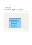
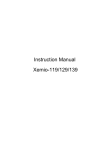
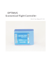
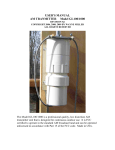
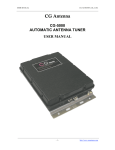
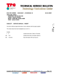
HF/VHF AUTOMATIC PLL SYNTHESIZED
ARDF TRANSMITTER
CONTEST 2002
instruction manual
INTRODUCTION
The first PLL synthesized fully programmable ARDF transmitter is designed for
any level of ARDF competition or training. The possibility of frequency adjustment
opens the new area in the ARDF competitions and allows using more transmitters
on different frequencies. All parameters are widely adjustable via user-friendly menu,
settings are stored in EEPROM memory.
After features are set, the operation is very easy: just install the antenna, plug in
the connector and transmitter automatically recognizes the proper band and starts
operation. If antenna is disconnected, the trasmitter turns to the STANDBY mode
(only 2 mA consumption) and after 30hours, turns off itself. The accumulator is
internally protected against deep discharge and its status is indicated at the end of
every relation.
For training purpose, you can use the transmitter without the external accumulator
( its weight will be then less than 1 kg).
Rugged, waterproof aluminum house protects the transmitter against the
environmental influences, anti-theft loop with cable lock protects it against stealing.
TABLE OF CONTENTS
INTRODUCTION
IMPORTANT
PRECAUTIONS
TABLE OF CONTENTS
UNPACKING
1
2
IMPORTANT!
Read this instruction manual carefully before attempting to operate the
transmitter.
Save this instruction manual. This instruction manual contains important safety
and operating instructions for the CONTEST2002.
3
PANEL DESCRIPTION
Top panel
Front panel
Front panel display
INSTALLATION
Unpacking
Before operating
Switching on
MODE selector
Clock synchronizing
3,5 MHz antenna installation
144 MHz antenna installation
Switching off
4
PARAMETER SETTING
General
Code and keying speed
Timing schedule
Frequency
Power
5
MAINTENANCE
Fuse replacement
Charging
Cleaning
6
TROUBLESHOOTING
7
SPECIFICATIONS
8
TECHNICAL INFORMATION
9
OPTIONS
10
WARRANTY, SERVICE
OTHER FEATURES
Supply
External accumulator
Band selecting
PRECAUTIONS
! NEVER
! NEVER
AVOID
apply AC or more than 16V DC to any socket of the transmitter.
This may cause fire or ruin the transmitter.
use any charger except for the one supplied by the
manufacturer. You may ruin the accumulator or even the whole
transmitter.
using or placing the tranmitter in the areas with temperatures below
-20°C or above +60°C.
Use only accessories supplied by the manufacturer..
UNPACKING
Accessories included with the CONTEST2002:
- antenna and counterpoise for 3,5 MHz band
- antenna and 2+2 elements for 144 MHz band
- external accumulator 12V/2,6 Ah.
- carrying case
- fuse F4A (2 pcs)
- this manual
1
Front panel display:
PANEL DESCRIPTION
START
STOP
Top panel:
3,5 MHz antenna tuning
anti-theft
loop
external
accumulator
connector
mode selector
12
12
12
12 contest 2002
12
12
12
12
12
12
12
12ACCU
ANT
12
12
12
12
ARDF TX
accu. voltage
indicator
antenna/charger/sync.
cable connector
1:08 MOS
60/240
MODE
REL
Push to turn the transmitter ON.
After turning on, the display shows
clock (in 5-minute cycle), code and
timing schedule
Pushing UP/DOWN buttons, you can go
through all menu items and check all
transmitter settings:
CONT
STBY
SET
1234567
1234567
12
12
1234567
1234567
12
ok2bwn
1234567
1234567
RADIO SPORTS
EQUIPMENT
CODE:MOS
SPD: 50
- transmitted code (MOS)
- keying speed (50 PARIS)
T:60/240
ST:0+120
- timing schedule (60s transmit, 240 s space)
- relation start (120s after 0:0)
f:
- 80m frequency (3,52 MHz)
- 2m frequency (144,50 MHz)
on air indicator
Front panel:
display
1:08 MOS
60/240
processor reset
ENTER button
(enters SET mode,
only while MODE
selector in the SET
position)
UP/DOWN buttons
(browse through
menu, change
values)
ENTER
START
STOP
START button
(turns on the
transmitter)
3.52
144.50
POWER:
HIGH
- output power (high)
Note: Menu checking has no influence
to the transmitter operation, even if it is
transmitting.
2
INSTALLATION
Unpacking
After unpacking, check carefully the transmitter and all accessories included. In the
case of any damage do not use the transmitter and contact immediately the manufacturer.
Before operating
Before the first usage, charge the accumulator for 24 hours. Please, use this time
for reading of this instruction manual.
Turning the transmitter ON:
START
STOP
Push the START button on the front panel. Clock and basic
setting information will appear on the display and the green
LED will flash on the top panel.
MODE selector
Selector has four positions:
• SET (setting) - enables settings change and transmitter shutdown.
• STBY (standby) - transmitter does not transmit, only logic unit is running.
Transmitter enters this state automatically also when no antenna is connected
or accumulator is discharged.
• REL (relations) - transmitter operates in relations according to the settings and
antenna connected.
• CONT (continuosly) - transmitter operates continuously according to the settings
and antenna connected.
Time base synchronization
• One transmitter starting
Turn on the transmitter exactly at the beginning of the 1st minute of the cycle.
• Starting the set of transmitters by means of a synchrocable
1. Turn on all transmitters (see above).
2. Connect grey connectors of the synchrocable to the sockets on top panels.
3. Exactly at the beginning of the 1st minute of the cycle push the button START on
the synchrocable.
4. Disconnect the synchrocable from all transmitters.
• Running transmitter restart
Exactly at the beginning of the first minute push the RESET button on the front
panel (by means of ballpoint pen, for example). The rest of the controls may remain
unchanged, the transmitter will keep operation as before, only the clock are restarted.
3,5 MHz antenna installation
3,5 MHz antenna consists of a counterpoise (the wire ended by a DIN connector)
and the radiator itself (the wire enden by a banana plug).
Lay the counterpoise wire on the ground, straight towards the competition starting
point. In case of the 3-radial counterpoise, lay the radials to all directions.
The radiator shall hang, for instance, from the tree branch. Use the whole length of
the radiator if possible. During dry weather, the radiator may lay even on the tree trunk
surface. During rain, when the trees are wet, the radiator shall better hang in a free
space.
Plug the banana plug into the socket at the counterpoise wire and the DIN connector
to the socket on the top panel of the transmitter.
Avoid close vicinity of large metal objects such as fences, rails or wires, which
disturb the electromagnetic field and makes the finding difficult.
NOTE: It is advisable to turn the counterpoise once around the tree in order to
prevent the plugs against whipping out when the competitor catches the counterpoise
wire.
Antenna tuning
Turn the MODE selector to the CONT position, then tune the antenna by the ANT
button. Try to reach the maximum brightness of the indicator. Then eventually turn to
the REL position. Do not touch the transmitter house while tuning.
144 MHz antenna installation
The 144 MHz antenna consists of an antenna body with cable and four elements
(two short and two long). Screw the elements into the antenna body - the shorter ones
horizontally and the longer tilted. Hang the antenna on the tree branch by the string
tied on the top of an antenna body. The coax cable shall lead vertically down.
Install the antenna as high as possible, 3 m at least. Plug the DIN connector to the
socket on the top panel. The 144 MHz antenna needs no tuning. The ANT indicator
shows only transmitted carrier.
Turning the transmitter OFF:
1:08 MOS
60/240
ENTER
SHUTDOWN
UP+DN!
1. manually: in the basic menu status (clock on the display) push the ENTER
button, then push UP and DOWN buttons simultaneously.
2. automatically - transmitter will automatically turn off itself 30 hours after the last
start or reset.
3
4
SETTINGS
General:
Any setting can be changed (or transmitter turned off) only with the MODE selector
in the SET position. In other positions, the menu items can be browsed and read only.
Settings change: select the wanted menu part by the UP/DOWN buttons, then
oush ENTER. Parameter menu will appear, current value flashes and can be changed
by the UP/DOWN buttons. Confirm the chosen value by ENTER, which possibly moves
you to the next menu item.
Settings are stored in non-volatile memory and remain there until they are again
user-changed.
OTHER FEATURES
Supply:
The transmitter is supplied by the built-in sealed lead 12V accumulator. As this
accumulator is sensitive to the deep discharge, there is two stage protection and
telemetric signalisation provided.
Under normal conditions (transmitter running, accumulator charged) there is green
indicator flashing on the top panel. If the transmitter operates in relations, every relation
ends with a long dash showing the normal accumulator voltage. No dash found at the
end of the relation means that the accumulator is exhausted and within next 10 to 30
minutes (according to the power and band) internal protection will disable the transmitter
in order to prevent the accumulator from deep discharge. The transmitter referee could
be warned in advance in order to use spare transmitter or external supply.
If the accumulator voltage sinks under 10,3V, the indicator on top panel goes out
and the transmitter turns to the STBY mode (see above). After normal accumulator
voltage recovers (by connecting the external accumulator, for example), the transmitter
continues in normal operation.
External accumulator
Using the external accumulator will extend the operating period four times. Put the
accumulator to the back carrying case compartment and connect it to th esocket on
the top panel. External accumulator is charged through the transmitter.
Band selecting:
The transmitter recognizes connected antenna and selects automatically the
appropriate band. If no antenna is connected, the transmitter turns to the STBY mode
(regardless of the MODE selector position).
Code and keying speed setting:
CODE:MOS
SPD: 50
ENTER
CODE:
MOS
CODE:
MOH
ENTER
SPEED:
50
ENTER
SPEED:
70
Code setting possibilities: MOE, MOI, MOS, MOH, MO5, MO, A...Z.
Keying speed setting possibilities: 35, 50, 70, 100 PARIS.
Setting the code MOE ... MO5 automatically adjusts the relation position in cycle
(see also below).
Timing schedule setting:
R:60/240
ST:0+120
ENTER
TIMING:
60/240
Frequency setting:
ENTER
TIMING:
30/120
START:0+
120
f:
ENTER
3.52
144.50
ENTER
The beginning of the relation can be shifted by any multiple of the relation length along
the whole 5-minute cycle. The MOE, MO, A ... Z codes have the default setting +0, it
means that the relation begins at the beginning of the cycle. The MOI ... MO5 codes
are on default adequately shifted in the cycle. This ofset can be, however, manually
changed to any desired value. Resetting the code will reset also the relation ofset to
the default.
ENTER
f 80m:
3.53
START:0+
180
Timing schedule setting possibilities:
60/240:
60 s transmitting, 240 s space
30/120:
30 s transmitting, 120 s space
30/270:
30 s transmitting, 270 s space
12/48:
12 s transmitting, 48 s space
15/45:
15 s transmitting, 45 s space
30/30:
30 s transmitting, 30 s space
15/15:
15 s transmitting, 15 s space
f 80m:
3.52
f 2m:
144.50
ENTER
f 2m:
144.55
Možnosti nastavení kmitoètu v pásmu 80m:
3,52 MHz
3,57 MHz
3,62 MHz
3,53 MHz
3,58 MHz
3,63 MHz
3,54 MHz
3,59 MHz
3,64 MHz
3,55 MHz
3,60 MHz
3,65 MHz
3,56 MHz
3,61 MHz
3,66 MHz
3,67 MHz
Možnosti nastavení kmitoètu v pásmu 2m:
144,50 MHz
144,67 MHz
145,20 MHz
144,55 MHz
144,75 MHz
145,33 MHz
144,60 MHz
144,85 MHz
145,50 MHz
Power setting:
VYKON:
VYSOKY
ENTER
VYKON:
VYSOKY
ENTER
VYKON:
NIZKY
Úroveò výkonu VYSOKÝ odpovídá pøibližnì výkonu 3W v pásmu 3,5 MHz a
3W PEP v pásmu 144 MHz, úroveò výkonu NÍZKÝ odpovídá výkonu 0,9W v
pásmu 3,5 MHz a 0,7 W PEP v pásmu 144 MHz.
5
MAINTENANCE
Fuse replacement:
Either built-in or external accumulators are protected against shortcontact by the
fuses o5x20mm, F4A. Replace the blown fuses with the ones of the same value only!
Procedure of fuse replacement:
1. Remove 2 screws on the sides of the bottom panel of the transmitter or external
accumulator and remove the panel.
2. The fuse position is shown at the pictures:
6
TROUBLESHOOTING
The following list is designed to help you correct problems which are not equipment
malfunctions. If you are unable to locate the cause of a problem or solve it through
the use of this list, contact the manufacturer.
After turning on the indicator does not flash but display shows normally
Possible cause: exhausted accumulator
Solution: recharge the accumulator immediately
After turning on the indicator does not flash and display is blank
Possible cause: blown fuse
Solution: check for possible cause, then replace the fuse
Release the fuse holder with a screwdriver (push and turn counterclockwise)
and remove it. Replace the blown fuse, put the holder back and secure it by
pushing and turning clockwise.
3. Put the bottom panel back and return the screws.
Charging
The charging period is 1-10 hours according to the discharge level. After the
accumulators are charged, the charger automatically switches to trickle charging.
The transmitters may remain connected to the charger even a day or two, but not
forever.
External accumulator is charged through the transmitter, being connected to the
socket on the top panel.
Keep the accumulators fully charged. Charge them after every competition and
also after the longer period of inactivity.
Cleaning:
Keep the transmitter dry and clean. If the transmitter becomes wet, dry it by the
clean cloth and let it dry in a room temperature. Never use strong heaters!
If the transmitter becomes dusty or dirty, clean it with a brush or a dry, soft cloth.
Avoid the use of strong chemical solvents such as benzine or alcohol to clean the
transmitter.
The transmitter needs no maintenance above the mentioned procedures.
Transmitted signal is distorted or interrupted
Possible cause: exhausted accumulator (protection starts activating)
Solution: recharge the accumulator immediately or connect the external
Transmitter poorly audible (3,5 MHz)
Possible cause: antenna not properly tuned or installed, radiator wire
whipped out of the socket
Solution: check for the antenna installation and/or tuning
Transmitter poorly audible (144 MHz)
Possible cause: antenna too low or tilted, element(s) lost
Solution: check for the antenna installation
Transmitter transmits wrong code or in wrong time
Possible cause: wrong settings, clock start
Solution: check for the settings, restart the clock
Transmitter does not respond to controls, does not transmit, strange
characters appear on the display
Possible cause: microsoftware malfunction, probably in connection with the
exhausted accumulator
Solution: push the Reset button on the front panel (with the ballpoint, for
example). If it will not help, remove the fuse for a while (and disconnect
the external accumulator)
7
8
SPECIFICATIONS
Top panel connector pin-out:
General
Supply
Operating temperature range
Storage temperature range
Covering
Transmitter:
Dimensions
Weight
External accumulator:
Dimensions
Weight
Operating period
(hrs, 3,5-144 MHz)
built-in accu only
with ext. accumulator
TECHNICAL INFORMATION
built-in sealed lead accumulator 12V/0,8Ah
or external sealed lead accumulator 12V/2,6Ah
-10...+ 60°C
-20...+ 60°C
IP65
80(Wx40(H)x195(D) mm (without projections)
970 g
80(W)x40(H)x195(D) mm
1430 g
REL
CONT
high power
12-17 2-3,5
50-70 10-15
4
144 MHz transmitter
Carrier frequency
Mode
Output RF power @ 50 ohm
Spurious emissions:
Antenna:
9 channels (144,5 ... 145,5 MHz)
A2A, keyed carrier, AM 75%
HIGH: 3 W PEP, LOW: 0.7 W PEP
less than -60 dB
omnidirectional turnstile
Logic unit
Transmitted codes
Keying speed:
Timing schedules:
Time stability
Firmware version:
MOE, MOI, MOS, MOH, MO5, MO, A ... Z
35,50,70 or 100 PARIS
60/240 (s, transmit/space), 30/120, 30/270,
12/48, 15/45, 30/30, 15/15
+-10 ppm (approx. 1 s/day)
V112GB
3
6
9
7
144 MHz antenna
common ground
3,5 MHz antenna
144 MHz band enable
3,5 MHz band enable
12V accumulator
reset
OPTIONS
Automatic charger for 1-6 transmitters
Synchro cable
Automatic DCF controlled synchronizer
Foxoring whip antenna
Various transmitting antennas
Cable lock
REL
CONT
low power
22-30 4,5-6
90-130 19-27
16 channels (3,52 ... 3,67 MHz)
A1A (CW)
HIGH: 3 W, LOW: 0.9 W
less than -66 dB
vertical wire 8 m + 8 m counterpoise
5
1
3,5 MHz transmitter
Carrier frequency
Mode
Output RF power @ 50 ohm
Spurious emissions:
Antenna:
2
1
2
3
4
5
6
7
10
WARRANTY, SERVICE
Should this equipment malfunction under normal use, it will be repaired without
charge for a period of one year from the date of purchase.
The customer shall not have any claim under this warranty for repair or adjustment
expenses if the trouble is caused by improper, rough or careless treatment or mechanical damage, by a fire or other natural calamity or by improper repair or adjustment made by anyone other than manufacturer.
The warranty does not cover the accumulators.
After the first year of use manufacturer offers the free of charge adjustment and
check of the equipment including the recalibration of clock and synthesizer.
Any other information, service or modifications are provided by the manufacturer:
Jiøí Mareèek, OK2BWN, Obøanská 593, CZ-664 01 Bílovice nad Svitavou
phone/fax +420 545227041, e-mail: [email protected]
always the right direction ...
Jiøí Mareèek, OK2BWN
CZ-664 01 Bílovice nad Svitavou, Obøanská 593
phone/fax +420 545227041, e-mail: [email protected]
http://www.marecek.sky.cz