1
W741E260
− Dual-clock slow operation mode: system is operated by the sub-oscillator
(FOSC = Fs and Fm is stopped)
• Five types of interrupts
− Four internal interrupts (Divider0, Divider1, Timer0, Timer1) for W741C260 body;
three internal interrupts (Divider0, Timer0, Timer1) for W741C250 body.
− One external interrupt (RC Port) for W741C260 body;
two external interrupts (RC port and INT pin) for W741C250 body.
• LCD driver output
− 32 segment x 4 common
− Static, 1/2 duty (1/2 bias), 1/3 duty (1/2 or 1/3 bias), 1/4 duty (1/3 bias) driving mode can be
selected
− LCD driver output pins can be used as DC output port by code option
− Clock source can be main oscillator clock in the single-clock operation mode, or sub-oscillator
clock in the dual-clock operation mode; operation mode is selected by code option
• MFP output pin
− Output is software selectable as modulating or nonmodulating frequency
− Works as frequency output specified by Timer 1
• Two built-in 14-bit frequency dividers
− Divider0: the clock source is the output of the main oscillator
− Divider1: the clock source is the output of the sub-oscillator
• Two built-in 8-bit programmable countdown timers
− Timer 0: one of two internal clock frequencies (FOSC/4 or FOSC/1024) can be selected
− Timer 1: includes an auto-reload function and one of two internal clock frequencies (FOSC or
FOSC/64) can be selected, or falling edge of pin RC.0 can be selected (output through MFP pin)
• Built-in 18/14-bit watchdog timer selectable for system reset
− Enable/Disable the watchdog timer can be controlled by command or by option code;
the control source (command or option code) can be determined by another option code
• Powerful instruction set: 118 instructions for W741C260 body
116 instructions for W741C250 body
• 8-level subroutine (include interrupt) nesting
• Up to 1 µS instruction cycle (with 4 MHz operating frequency)
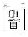
• Packaged in 80-pin QFP
-3-
Publication Release Date: March 1998
Revision A2