1
W741E260
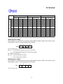
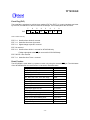
If the Timer 0 clock input is FOSC/4:
Desired time interval = (preset value +1) × 4 × 1/FOSC
If the Timer 0 clock input is FOSC/1024:
Desired time interval = (preset value +1) × 1024 × 1/FOSC
Preset value: Decimal number of Timer 0 preset value, and
FOSC: Clock oscillation frequency
1. Reset
2. CLR EVF, #02H
3. Reset MR0.3 to 0
4. MOV TM0L, R or MOV TM0H, R
MR0.0
Disable
Fosc/1024
HEF.1
8-bit Binary
Down Counter
(Timer 0)
Fosc/4
Enable
R
Hold mode release (HCF.1)
Q
IEF.1
EVF.1
8
MOV TM0H, R
Timer 0 interrupt (INT1)
4
4
1. Set MR0.3 to 1
2. MOV TM0, #I
S
MOV TM0L, R
1. Reset
2. CLR EVF, #02H
3. Set MR0.3 to 1
4. MOV TM0, #I
MOV TM0, #I
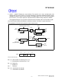
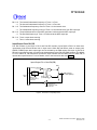
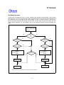
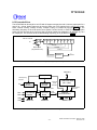
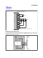
Figure 6. Organization of Timer 0
2. Timer 1 (TM1)
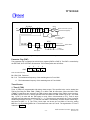
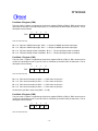
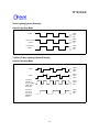
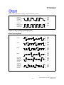
Timer 1 (TM1) is also a programmable 8-bit binary down counter, as shown in Figure . Timer 1 can be
used as a counter to count external events or to output an arbitrary frequency to the MFP pin. The
input clock of Timer 1 can be one of three sources: FOSC/64, FOSC, or an external clock from the RC.0
input pin. The source can be selected by setting bit 0 and bit 1 of mode register 1 (MR1). At initial
reset, the Timer 1 clock input is FOSC. If an external clock is selected as the clock source of Timer 1,
the content of Timer 1 is decreased by 1 at the falling edge of RC.0. When the MOV TM1L, R or MOV
TM1H, R instruction is executed, the specified data are loaded into the auto-reload buffer and the TM1
down-counting will be disabled (i.e. MR1.3 is reset to 0). If the bit 3 of MR1 is set (MR1.3 = 1), the
contents of the auto-reload buffer will be loaded into the TM1 down counter, Timer 1 starts to down
count, and the event flag 7 is reset (EVF.7 = 0). When the MOV TM1, #I instruction is executed, the
event flag 7 (EVF.7) and MR1.3 are reset and the specified value is loaded into auto-reload buffer and
TM1 by the internal hardware, then the MR1.3 is set, that is the TM1 starts to count by the hardware.
When the timer decrements to FFH, it will generate an underflow (EVF.7 = 1) and be auto-reloaded
with the specified data, after which it will continue to count down. An interrupt is executed if the
interrupt enable flag 7 has been set to 1 (IEF.7 = 1), and the hold state is terminated if the hold mode
release enable flag 7 is set to 1 (HEF.7 = 1). The specified frequency of Timer 1 can be delivered to
the MFP output pin by programming bit 2 of MR1. Bit 3 of MR1 can be used to make Timer 1 stop or
start counting.
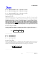
If the Timer 1 clock input is FT, then:
- 14 -