1
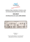
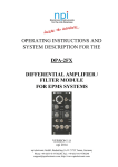
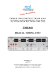
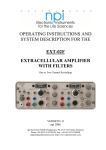
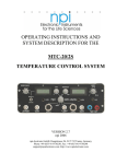
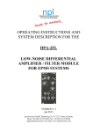
OPERATING INSTRUCTIONS AND
SYSTEM DESCRIPTION FOR THE
LHBF-48X
AMPLIFIER / FILTER SYSTEM
with 4-pole BESSEL filter
VERSION 2.1
npi 2014
npi electronic GmbH, Bauhofring 16, D-71732 Tamm, Germany
Phone +49 (0)7141-9730230; Fax: +49 (0)7141-9730240
[email protected]; http://www.npielectronic.com
LHBF-48X User Manual
_______________________________________________________________________________________________________________
Table of Contents
1. Safety Regulations .............................................................................................................. 3
2. LHBF-48X Components ..................................................................................................... 4
3. LHBF-48X Amplifier / Filter.............................................................................................. 4
3.1. System Description ...................................................................................................... 4
3.2. Signal Flow Diagram ................................................................................................... 4
3.3. Description of the Front Panel and Operation ............................................................. 5
3.4. Description of the Rear Panel ...................................................................................... 9
4. Literature ............................................................................................................................. 9
5. Technical Data .................................................................................................................... 10
___________________________________________________________________________
version 2.1
page 2
LHBF-48X User Manual
_______________________________________________________________________________________________________________
1. Safety Regulations
VERY IMPORTANT: Instruments and components supplied by npi electronic are NOT
intended for clinical use or medical purposes (e.g. for diagnosis or treatment of humans),
or for any other life-supporting system. npi electronic expressively disclaims any
warranties for such purpose. Equipment supplied by npi electronic shall be operated
only by selected, trained and adequately instructed personnel. For details please consult
the GENERAL TERMS OF DELIVERY AND CONDITIONS OF BUSINESS of npi
electronic, D-71732 Tamm, Germany.
1)
GENERAL: This system is designed for use in scientific laboratories and should be
operated by trained staff only. General safety regulations for operating electrical devices
should be considered.
2)
AC MAINS CONNECTION: While working with the npi systems, always adhere to the
appropriate safety measures for handling electronic devices. Before using any device
please read manuals and instructions carefully.
The device is to be operated only at 115/230 Volt 60/50 Hz AC. Please check for
appropriate line voltage before connecting any system to mains.
Always use a three-wire line cord and a mains power-plug with a protection contact
connected to ground (protective earth).
Before opening the cabinet, disconnect mains power-plug.
Disconnect mains power-plug when replacing the fuse or changing line voltage. Replace
fuse only with an appropriate specified type.
3)
STATIC ELECTRICITY: Electronic equipment is sensitive to static discharges. Some
devices such as sensor inputs are equipped with very sensitive FET amplifiers, which can
be damaged by electrostatic charge and must therefore be handled with care. This can be
avoided by touching a grounded metal surface when changing or adjusting sensors.
Always turn power off when adding or removing modules, connecting or
disconnecting sensors, headstages or other components from the instrument or 19”
cabinet.
4)
TEMPERATURE DRIFT / WARM-UP TIME: All analog electronic systems are
sensitive to temperature changes. Therefore, all electronic instruments containing analog
circuits should be used only in a warmed-up condition (i.e. after internal temperature has
reached steady-state values). In most cases a warm-up period of 20-30 minutes is
sufficient.
5)
HANDLING: Please protect the device from moisture, heat, radiation and aggressive
chemicals.
___________________________________________________________________________
version 2.1
page 3
LHBF-48X User Manual
_______________________________________________________________________________________________________________
2. LHBF-48X Components
The following items are shipped with the LHBF-48X amplifier / filter:
3 LHBF-48X 19” cabinet
3 Power cord
3 User manual
3. LHBF-48X Amplifier / Filter
3.1.
System Description
The LHBF-48X amplifier/filter is designed for processing small bio-electrical signals. The
input voltage range is ±12 V. Two overload-LEDs indicate that the amplifier is going to leave
its linear range (±12 V), i.e. that the OUTPUT voltage exceeds ±10 V. All inputs and outputs
are BNC connectors.
The unit is equipped with a differential input stage with an AC / 0 / DC switch for each input.
The input stage is followed by the offset compensation (see Figure 1).
The GAIN stage allows amplification of the signal from 1-1000 in 1-2-5 steps. The GAIN is
selected by an 10-position rotary switch.
The amplified signal is passed through the HIGHPASS (optional) and LOWPASS filter. The
four-pole Bessel LOWPASS FILTER has sixteen corner frequencies (20 Hz - 20 kHz). The
LOWPASS FILTER can also be bypassed by using a toggle switch.
The one-pole HIGHPASS FILTER has fifteen corner frequencies (0.1 Hz - 3 kHz) and a DC
position.
The OFFSET is indicated by an analog meter (range ±30 mV). The OFFSET cancellation
range is ±0.1 V to ±10 V. The OFFSET is cancelled by setting two controls, a ten-turn
potentiometer and a ±0.1 V, ±1 V, ±10 V range switch.
DC offsets can be compensated either by the using the OFFSET control or they can be
eliminated using the AC position of the input switches or by using the HIGHPASS filter.
The positions of GAIN and FILTER switches can be read from monitor outputs (1V/step).
3.2.
Signal Flow Diagram
The signal is passed through the LHBF-48X as shown below:
Figure 1: signal flow diagram
___________________________________________________________________________
version 2.1
page 4
LHBF-48X User Manual
_______________________________________________________________________________________________________________
3.3.
Description of the Front Panel and Operation
Figure 2: LHBF-48X front panel view (the numbers are related to those in the text below)
___________________________________________________________________________
version 2.1
page 5
LHBF-48X User Manual
_______________________________________________________________________________________________________________
In the following description of the front panel elements each element has a number that is
related to that in Figure 2. The number is followed by the name (in uppercase letters) written
on the front panel and the type of the element (in lowercase letters). Then, a short description
of the element is given. Some elements are grouped in functional units (e.g. INPUT unit) and
are described as units regardless of the order of numbers.
(1) POWER pressure switch
Switch to turn POWER on (switch pushed) or off (switch released).
FILTER unit
The filter unit consists of (2) HIGHPASS filter (optional) and (3)
LOWPASS filter.
(2)
LOWPASS filter rotary switch
Four pole LOWPASS filter with -24 dB / octave. Corner frequencies: 20, 50, 100,
200, 300 500, 700, 1k, 1.3k, 2k, 3k, 5k, 8k, 10k, 13k, 20k Hz.
(3)
HIGHPASS FILTER rotary switch (optional)
Single pole HIGHPASS filter with 6 dB / octave. Corner frequencies: 0.1, 0.3, 0.5, 1,
3, 5, 10, 30, 50, 100, 300, 500, 800, 1k, 3k Hz. In DC position the filter is disabled.
(4) FILTER switch
Switch to set the LOWPASS and HIGHPASS FILTER (switch position FILTER) or to
bypass the both FILTERS (switch position BYPASS).
(5) ZERO ADJUST potentiometer (not installed)
(6) OUTPUT BALANCE monitor
Analog monitor that displays the OFFSET in the range of ±300 mV for optimal
cancellation.
(7) GAIN rotary switch
10-position rotary switch to set the amplification factor of the incoming signal
(range: 1 to 1000).
___________________________________________________________________________
version 2.1
page 6
LHBF-48X User Manual
_______________________________________________________________________________________________________________
OFFSET unit
The OFFSET unit consists of OFFSET RANGE rotary switch (8) and
OFFSET potentiometer (9).
(8) OFFSET RANGE rotary switch
4-position rotary switch to set the RANGE of the OFFSET potentiometer (#9) (OFF,
±0.1 V, ±1 V, ±10V).
(9) OFFSET potentiometer
10-turn potentiometer to compensate for the OFFSET of a DC signal. The OFFSET
range is set by a switch (#11).
Note: Position 5 of the OFFSET control corresponds to 0 mV OFFSET. The offset
compensation only works if the input coupling switch (#10, #11) is set to DC and the
HIGHPASS FILTER (#2) is set to OFF.
INPUT unit
The input coupling unit consists of input coupling switches (10, 11) and input
connectors (12, 13).
The position of the input coupling switches decides how the input signals are coupled:
AC: the input signal is AC coupled with a corner frequency of 0.1 Hz, e.g. DC offsets were
cancelled
DC: the input signal is DC coupled
0:
the input signal is grounded
(10) DC / 0 / AC switch
Switch to select the coupling of an incoming signal (AC or DC) for -IN. Position 0 links
the respective INPUT connector (#13) to ground.
(11) DC / 0 / AC switch
Switch to select the coupling of an incoming signal (AC or DC) for +IN. Position 0
links the respective INPUT connector (#12) to ground.
(12) +IN connector
BNC connector to connect the signal to be processed.
(13) -IN connector
BNC connector to connect the signal to be processed.
___________________________________________________________________________
version 2.1
page 7
LHBF-48X User Manual
_______________________________________________________________________________________________________________
The INPUTS can be used in single-ended or differential configuration. For single-ended
operation connect the signal to be processed to the +IN or –IN connector and set the other (not
used) input to ground using the respective toggle switch (set #11 or #12 to 0 position).
In differential configuration the signal that is connected to –IN is subtracted from the signal
that is connected to +IN.
Important: If only one INPUT is used (single-ended configuration), the other should be linked
to ground (see also #10, #11) to avoid coupling of noise.
(14) +/- OVER LEDs
Two overload-LEDs indicating that the amplifier is going to leave its linear
range (±12 V), i.e. that the OUTPUT voltage exceeds ±10 V.
(15) OUTPUT connector
BNC connector providing the processed signal.
(16)
NOTCH FILTER switch (optional)
Switch to set the NOTCH FILTER (50 Hz / 60 Hz) (switch position NOTCH
FILTER) or to bypass the NOTCH FILTER (switch position OFF).
(17) GAIN MONITOR connector
BNC connector monitoring the position of the GAIN switch (+1V…+10V, 1V /
step).
(18) HIGHPASS MONITOR connector (optional)
BNC connector monitoring the position of the HIGHPASS FILTER switch
(-7V…+8, 1V / step).
(19) LOWPASS MONITOR connector
BNC connector monitoring the position of the LOWPASS FILTER switch
(-7V…+8V, 1V / step).
(20) GROUND connector
Banana plug for grounding. This connector is linked to the internal system ground
which has no connection to the 19" cabinet and the mains ground to avoid ground
loops.
___________________________________________________________________________
version 2.1
page 8
LHBF-48X User Manual
_______________________________________________________________________________________________________________
3.4.
Description of the Rear Panel
Figure 3: LHBF-48X rear panel view (the numbers are related to those in the text below)
(1) Mains connector
Connector for mains.
(2) Voltage selector
Turning knob for selecting the mains voltage, 115 V or 230 V.
Important: Switch always to the appropriate mains voltage before connecting the filter to
mains.
(3) Fuse selector
Turning knob for the fuse holder. Turn counterclockwise to open.
Important: Use always the appropriate fuse for the present mains voltage before connecting
the filter to mains (230 V / 0.2 A; 115 V / 0.4 A, slow).
(4) Cassis connector
This banana jack is linked to the chassis. It can be used for grounding the housing of the
LHBF-48X.
(5) Ground connector
This banana jack is linked to the internal system ground which has no connection to the 19"
cabinet and to mains ground to avoid ground loops.
4. Literature
o Kettenmann, H. & Grantyn, R. (eds.) (1992) Practical Electrophysiological Methods,
WileyLiss, New York
o Ogden DC (1994) Microelectrode Techniques. The Plymouth Workshop Handbook
o Second Edition, The Company of Biologists Limited, Cambridge
o Tietze, U and Ch. Schenk (1999) Halbleiter-Schaltungstechnik (Semiconductor
Techniques) 11. Edition, Springer, Berlin, Heidelberg, New York [English version
available].
o Windhorst, U. and H. Johansson (eds.) (1999) Modern Techniques in Neuroscience
Research, Springer, Berlin, Heidelberg, New York
___________________________________________________________________________
version 2.1
page 9
LHBF-48X User Manual
_______________________________________________________________________________________________________________
5. Technical Data
Input:
Input range:
Input impedance:
AC-coupling at input:
Differential input:
±12 V
1 MΩ
Corner frequency of 0.1 Hz
CMR >90 dB
Output:
Full power bandwidth:
Range of output:
Output impedance:
Overload LED threshold:
Gain monitor:
Frequency monitors:
30 kHz
max. ±12 V
50 Ω
±10 V
1V/switch step, +1V…+10V
1V/switch step, -8V…+7V
Lowpass filter:
Filter type:
Attenuation:
Corner frequencies (Hz):
4-Pole Bessel filter
-24 dB / octave
20, 50, 100, 200, 300 500, 700, 1k, 1.3k, 2k, 3k, 5k, 8k, 10k, 13k,
20k Hz
Highpass filter (optional):
Filter type:
Attenuation:
Corner frequencies (Hz):
single pole filter
-6 dB / octave
DC, 0.1, 0.3, 0.5, 1, 3, 5, 10, 30, 50, 100, 300, 500, 800, 1k, 3k Hz
Gain:
Ten steps:
1, 2, 5, 10, 20, 50, 100, 200, 500, 1000
Offset compensation:
Three ranges:
±0.1 V, ±1 V or ±10 V
Power requirements:
19” rackmount cabinet:
230V/115V AC, 20 W, fuse 0.2A/0.4A, slow
___________________________________________________________________________
version 2.1
page 10