1
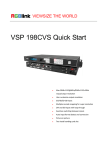
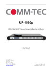
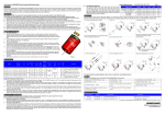
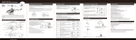
VSP 198CVS – Quick Start
NOTE
For full installation, configuration, and operation details, please refer to
the VSP 198CVS user manual.
This guide provides quick start instructions for an experienced installer
to set up and operate the VSP 198CVS.
Installation and cabling features
Rear Panel
Connections
1 3 CVBS Input
2 4 VGA Input
5
6
7
8
9
10
11 19
SDI Input
SDI Loop Out
Push button switch
10/100M Interface
USB Interface
RJ11(RS232) Interface
Sending card interface
Power Switch
12
13
HDMI Input
DVI Input
14
DVI Loop Out
15
16 17 DVI Output
18
VGA Ouput
Power interface
20
Step 1-Mounting
Turn off or disconnect all equipment power sources.
Step 2-SDI Input
Standard BNC connector, support
3D/HD/SD-SDI.
Step 3-CVBS Input
Composite video input (BNC connector).
Support composite signal include: PAL,
NTSC,SECAM.
Step 4-DVI Input
Used to input DVI signal from DVI
player or computer with DVI connector.
Step 5-VGA Input
Used to input VGA signal from VGA
player or computer with VGA connector.
Step 6-HDMI Input
HDMI-A interface, can be compatible
with HDMI inputs.
Step 7-SDI Loop Through Output
Standard BNC connector, can connect
t he device wit h SDI input or S DI
monitor.
Step 8-DVI Loop Through Output
Can connect the device with DVI
input or DVI monitor.
Step 9-DVI Output
Connect to the monitor or LED screen
which has DVI interface.
Step 10-VGA Output
Can connect the device with VGA
input or VGA monitor.
VSP 198CVS Quick Start
Rev 1.0
Page 1 of 3
Step 11-10/100M interface
H SIZE: this device display image Width setting.
Used to connect the computer or console.
Support the speed of network connection
with 10M or 100M.
V SIZE: this device display image Height setting.
Step 12-RS232 interface
Used to connect the computer or console.
How to Set up the Size and Position of the
Single Image.
Step 13-USB interface
The first step press the SCALE button ,enter the SCALE
Used to connect the computer or console.
Step 14-Sending Card interface
Sending card module port. Power has been already
supplied by video processor itself, no external power
supply needed for sending card.
Step 15-Power Interface and Switch
AC 85-264V 50/60Hz IEC-3 Power Interface .
RESET:Restore the factory Settings.
function menu.
The second step touch the knob and turn the knob,open
split function .
H SIZE: Width setting.
V SIZE: Height setting.
H Pos: Horizontal phase setting.
V Pos: Vertical phase setting.
How to do customized output resolution
The first step push [MENU] button to open the main
menu.
Connect with power cable, press the “POWER” and the The second step turn Knob and go to <OUTPUT
power indicator is turned on and after 10 seconds, the
FORMAT>.
monitor will be switched on and get into working status. The third step push knob and confirm to go into the
<OUTPUT FORMAT > menu.
Local Control
Front Panel Operation
Step 16-Power On
STANDARD: standard resolution.
CUSTOMIZED: user defined resolution setting.
User Guideline
How to Set up image zoom
The first step push [MENU] button to go into the main
menu.
The second step turn Knob goes to ZOOM menu .
The third step push Knob to confirm to go inside
ZOOM menu.
Inputs cable ,outputs cable , control cable ,power cable
were connected to interface finish turn on the power
switch,user guideline :
The fist step set up OLED display language .
The second step set up output format.
The third step set up LED screen height size.
The fourth step set up LED screen width size.
The fifth step set up LED screen horizontal size.
The sixth step set up LED screen Vertical size.
The seventh step set up input source.
The eighth step up save .
V UP:Zoom in vertical and the image will be zoom
How to Set up the SPLIT
down direction from its middle part.
The first step pushress the SPLIT button, the button
led light will turn on ,enter the SPLIT function menu.
The second step push and turn the knob ,will enable
open split function.
H TOTAL: LED screen Horizontal total size.
V TOTAL: LED screen Vertical total size.
H POS: this device display image Horizontal size
V POS: this device display image Vertical size.
in to the top direction from its bottom part .
V DOWN:Zoom in vertical and the image will be
zoom in to the down direction from its top part.
V UP/DOWN:Zoom in vertical but in both top and
H LEFT:Zoom in horizontal and the image will be
zoom in to the left direction from its right part.
H RIGHT:Zoom in horizontal and the image will
be zoom in to the right direction from its left part.
H IEFT/RIGHT:Zoom in horizontal but in both left
and right direction from its middle part.
CENTER:Zoom in 4 corner direction from center.
VSP 198CVS Quick Start
Rev 1.0
Page 2 of 3
How to Realize the Text Overlay Setting
The first step press MENU button, rotate the
knob,choose【TEXT OVERLAY】 and enter【TEXT
OVERLAY】, press the knob to confirm.
The second step rotate the knob, choose TEXT
OVERLAY mode, choose ON, TEXT OVERLAY function
open.
The third step press MENU, return to 【TEXT
OVERLAY】, rotate the knob, OLED screen displays
menu options, select 13 modes in PRESET, or select
BLEND, which includes two modes.
The forth step press MENU, return to【TEXT
OVERLAY】, rotate the knob, choose ABOVE/BELOW
to select the layer position for IMAGE B .
The fifth step press MENU, return to【TEXT
OVERLAY】, rotate the knob, choose BLEND LEVEL,
and set the image display transparency, regulating range
between 0 – 16.
The sixth step press MENU, return to【TEXT
OVERLAY】, rotate the knob, choose the color value.
The seventh step you can view the effect through the
screen, to get a better setting.
How to realize LAN remote control settings
The first step LAN physical connection. Connect VSP
628S and router with network cable then connect
computer and router with network cable also, use the
LAN port of router WAN port is used for connecting
to outer net.
The second step IP address setting (processor’s default
IP address is 192.168.0.100).
Common Questions and Solution
Screen is black after boot
1. Check if "POWER" key lights. If the light goes
out, please check if power is disconnect, and press
"POWER" key again.
2. Check if input the signal, if screen displays < NO
INPUT >, then there is no input signal.
3. If there is input signal, press "SOURCE" key and
switch the signals, and the screen will be normal.
Screen has no output image
1. Check if connect the wrong interface.
2. Check if the input and output interfaces are in
good connection.
3. Check if support the resolution.
4. Check if select the right signal source.
Display flips
Enter into the "Menu" option, select "SYSTEM", then
select "FLIP", push "OK" rotary, select "OFF", and
press "OK" key to ensure.
There is no audio output
Check if input the wrong signal, only SDI, HDMI
(supported by DVI input) are available for audio
monitoring.
Screen protector installation
1 . Clean the device screen throughly with cleaning
cloth. Make sure the surface is completely dry before
you apply the screen protector.
2. Peel down a small portion of the PET material layer
labeled “step 1” (This side is applied to the screen).
How to Realize Single Image Switching
3. Align and apply the exposed portion along one side
The first step boot the system default CV1 to the current of the screen. Lift and reapply until correct. Peel off the
reset of the mask and slowly brush down.
input source (key light and scintillation), if need
4. Remove the electrostatic layer labeled “step 2”.
seamless switching other source such as DVI, direct
Gently brush out any air bubbles by the air bubble
light touch DVI key.
The second step choose DVI buttons, button lamp CV1 scraper.
destroy, and DVI key light and shining, can realize
Screen protector removal
single image of input signal source switching (input
The screen protector film can be easily removed by
signal source by original CV1 switching to DVI).The
releasing the air vacuum which can be done by:
same method can be switched CV2, VGA1, VGA2,
1 . Using a piece of strong adhesive to lift one of the
DVI,HDMI, SDI.
corners.
2 . By sliding a thin piece of plastic polymer between
How to Set up the PIP
the screen protector film and the device.
Press the PIP button ,button led light turn on ,enter the
Note: screen protector can be cleaned with water and
pip function menu.
used repeatedly.
LAYOUT: Can choose PIP layout.
SWAP IMAGE: It can set PIP to swap exchange, when
choose ON, it can realize the main and sub-picture
exchange.
ALPHA: Can set the image display transparency,
regulating range between 0 – 16.
SELECT: Can choose to set the size or position of
IMAGE A or IMAGE B individually.
VSP 198CVS Quick Start
Rev 1.0
Page 3 of 3