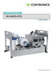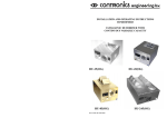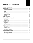
1
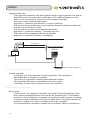
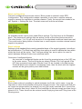
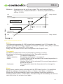
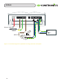
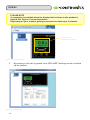
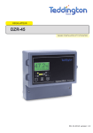
CONTROLLER
DZR-45
USER MANUAL
04-12-2014 version 1.5
DZR-45
Contronics Engineering B.V., Ambachtsweg 8, 5492 NJ Sint-Oedenrode, The Netherlands,
hereby declares that the product DZR-45, produced and delivered by Contronics Engineering
B.V., are in accordance with the following CE directives:
EMC-Directive : 2004/108/EG
Directive for low-voltage
electrical installation : 2006/95/EG
2
DZR-45
Table of content
1. PREFACE��������������������������������������������������������������������������������������������������������� 4
2. INTRODUCTION��������������������������������������������������������������������������������������������� 4
3. CONTENT OF THE DELIVERY�������������������������������������������������������������������� 4
4. DESCRIPTION OF THE CONTROLLER���������������������������������������������������� 5
5. WALL-MOUNTING OF THE CONTROLLER��������������������������������������������� 6
6. connections���������������������������������������������������������������������������������������������� 7
7. OPERATION����������������������������������������������������������������������������������������������������� 8
8. SCREEN SETTING����������������������������������������������������������������������������������������� 9
9. TECHNICAL DATA��������������������������������������������������������������������������������������� 14
10. MENU OVERVIEW������������������������������������������������������������������������������������� 15
11. factory setting and RANGE���������������������������������������������������������� 16
12. OPTION DZR-45NET��������������������������������������������������������������������������������� 21
3
DZR-45
1. PREFACE
This user manual contains the operating and installation instructions for the DZR-45
model controller.
2. INTRODUCTION
The DZR-45 is a hygrostat used to accurately regulate air humidity in rooms.
The DZR-45 is fitted with the following as standard:
- Graphic readout screen (multi-lingual).
- LED bar readout of the proportional control.
- LED indicators for humidification and dehumidification.
- Main switch 230V.
- Touch key operation.
- Bandwidth setting.
- Dead zone setting.
- Maximum/minimum setting.
- Offset for the sensors.
- Hygrostat function (2x).
- Thermostat function (2x).
- Capacity control.
- Proportional control (2x) 0-10 Volt.
- Relay control (4x).
- Connection for 2 humidity/temperature sensors.
3. CONTENT OF THE DELIVERY
When you receive the controller, the package must contain the following items:
DZR-45 controller
2 M16 screws
2 M20 screws
User manual
4
DZR-45
4. DESCRIPTION OF THE CONTROLLER
A
B
C
D
SET
Hygrozone DZR-45
Made in Holland
E
F
G
H
I
J
Figure 1. Description and connections
A Readout window
B Indication LEDs
CPushbuttons
D Securing screw for the upper cover
E On/Off switch
F Holes for wall mounting
G Perforated plate
H Mounting screws for perforated plate (M4 x 8mm)
I Screws for the connection compartment cover (M4 x 8mm)
J Connection compartment cover
5
DZR-45
5. WALL-MOUNTING OF THE CONTROLLER
At least 26 cm.
Object or
wall
Eye level
SET
Hygrozone DZR-45
Made in Holland
Figure 2. Installation of the controller
The controller must be mounted on an interior wall, preferably in a clean room where
the humidity level is not excessive. Do not mount the controller above a heating system
or the like. When installing, ensure that the display is located at eye level and that the
perforated plate (Fig. 1, item G) is facing downwards. Keep an area of up to 26 cm free
to the left of the controller to ensure that the cover can be opened (see Fig.2).
Open the cover of the controller by removing the screw from the upper cover (see
Fig. 1, item D). Remove the cover from the connection compartment (Fig. 1, item J)
by removing the two retaining screws. There are 4 mounting holes: 2 in the top corners
of the housing, and 2 at the bottom (Fig. 1, item F). M4 or M5 screws can be used for
these holes. You will find the hole pattern in the diagram below:
193 mm
222 mm
Figure 3. Mounting holes pattern.
IMPORTANT
If you wish to make holes in the perforated plate (Fig. 1, item G), please ensure
that the cover (J) of the connection compartment is positioned correctly. Then
carefully make the required number of holes using a hammer.
6
DZR-45
6. connections
1 2
3 4 5 6 7
8 9 10 11 12 13
C NO
Relay 4
C NO C NC NO C NC NO L’ L
Relay 3 Relay 2
N
Relay 1
Figure 4. Connections
HS-91 connections
Connection
Colour
Description
1
Brown
Sensor 2 – HS-91 +12V
2
Grey
Sensor 2 – HS-91 RH
3
Yellow
Sensor 2 – HS-91 temperature
4
Green
Sensor 2 – HS-91 0V
5
Brown
Sensor 1 – HS-91 +12V
6
Grey
Sensor 1 – HS-91 RH
7
Not used
8
Yellow
Sensor 1 – HS-91 temperature
9
Green
Sensor 1 – HS-91 0V
HS-10 connections
Connection
Colour
Description
5
Brown
Sensor 1 – HS-10 +12V
7
White
Sensor 1 – HS-10 RH
9
Green
Sensor 1 – HS-10 0V
HK-01 connections
Connection
Colour
Description
10
White
0-10V dehumidification output
11
Brown
0V
12
White
0-10V humidification output (HK-01)
13
Brown
0V
7
DZR-45
Relais connections
Relay
Function
1
Humidification
2
Dehumidification or humidification 2
3
Thermostat
4
Alarm
230V connection
Connect the incoming mains voltage to terminals L and N. When the main switch is set
to ‘On’, L will be connected through to L’.
It is then possible to connect, a humidifier to L’, for example.
IMPORTANT
- Ensure that all the connections are soldered when lengthening a cable.
- In order to prevent interference, ensure that low-voltage cables (0-10V) are never installed parallel to high-voltage lines (230V).
- Sensor wiring must cross electricity lines at a 90˚ angle.
Optimization of energy and water consumption.
A humidifier also uses energy (10 Watt) and water (rinse program) in the stand-by position (230V switched on, no humidity generation).
You can reduce this by switching off the humidification completely if the RH is 10%
higher than desired. The dehumidification relay is used for the connection. The
dehumidification bandwidth must thereby be set to 10%. Up to and including the HU-85,
the humidifier can be connected directly to the relay. If an HU-245 humidifier is
installed, an auxiliary relay must be used. See the connection diagram on page 20.
7. OPERATION
Readout window
LED indication humidification
relay switched on
LED indication humidification
switched on
LED indication dehumidification
relay switched on
Indication 0-10 Volt level
LED indication dehumidification
switched on
On/Off switch
Pushbuttons
Figure 5. Operation.
8
DZR-45
Press
to go to the menu.
Select the desired menu item using the
or
button.
Press
to confirm the selected item.
Select <<<< and press
to leave a (sub)menu.
If no buttons are operated for 1 minute, the menu screen will switch off.
SET
SET
SET
IMPORTANT
Some of the menus are hidden from the user if they have no influence on the
operation of the controller.
For example: In a single hygrostat configuration, the menu for hygrostat 2 is
not visible.
8. SCREEN SETTING
Main screen and sensor screen
The main screen is displayed as standard. The screen displays the measured and set
relative humidity. The sensor screen displays all the values measured at the connected
sensors.
Press the
button in order to display the sensor screen, and also use the button to
return to the main screen.
Figure 6. Main screen. Figure 7. sensor screen.
Language setting
Press
Scroll to System using the
button.
or
Press
Scroll to Language using the
or
button.
Press
Select the language using the or
button.
Press
Scroll to <<<< using the
or
button.
to leave the menu.
Press
SET
SET
SET
SET
SET
Basic configuration for DZR-45
The DZR-45 has 3 different configurations, which can be selected via this menu.
Single hygrostat
Single hygrostat with 1 humidity sensor, 1 humidification output and
1 dehumidification output. For more data, see General Hygrostat Operation.
9
DZR-45
Hygrostat with max.
This hygrostat operates in the same manner as the single hygrostat, but with an
additional sensor for maximum humidification. The additional sensor can be
placed in an air channel in order to limit the maximum humidity.
The sensor can be selected as follows:
Hygrostat -> maximum humidification -> sensor selection.
This will limit the humidification as soon as the measured relative humidity has reached the set maximum value.
The set maximum value can be adjusted as follows:
Hygrostat -> maximum humidity -> humidity set point.
The setting for the bandwidth can be found under:
Hygrostat -> maximum humidity -> bandwidth.
Ca. 500 cm
HS/91 in duct (Sensor 2)
DZR-45
HK-01
0-10 Volt
HS/91 in room (Sensor 1)
Figuur 8. Hygrostat with maximun control.
Double hygrostat
In principle, this is the same as 2 single hygrostats. The regulation of
dehumidification is hereby not possible.
The output of hygrostat 2 uses the dehumidification output.
Two hygrostat submenus are available in the main menu.
In this way, 2 areas can be monitored with one controller.
Figure 7. General hygrostat operation
Block mode
In block mode, the regulator is divided into several blocks with settings. Each
block can be activated based on time and/or an external signal. This makes it
possible for the configuration to operate during the day with a variety of settings.
It is also possible to indicate a fluid type for each block. This feature allows the
regulator to supply R.O. water or another fluid to the humidifier.
For comprehensive information, please refer to chapter X Block configuration
10
DZR-45
Block configuration
The block configuration becomes active if Block mode is selected under DZR
Configuration. This configuration makes it possible to use time or another external
signal to operate the regulator in another manner. Firstly, the correct time needs to be
set. System -> Setting the time. The start screen will now be as follows:
All available blocks can be seen under Block settings. The first block is the Standard
block. This features all settings that are active if none of the other blocks are active.
The other blocks (1 to 10) will only be active if the stipulated conditions have been met.
This could involve being within a certain time or could require a certain external control
signal to be present.
Block settings
Settings in the standard block mainly resemble those of the single hygrostat, but without
de-humidification. The Start time and Stop time setting is used to indicate the time within
which the block will be active. The Fluid type setting can, as an option, be used to
switch between different fluids via an electrical valve.
Overview of configured blocks
An overview of configured blocks can be found by pressing twice on the [UP} key
in the main screen. The first 4 blocks are shown. Blocks 5 to 8 will appear if the
[UP] key is pressed once again. Blocks 9 and 10 are located in the final screen.
If several blocks are subject to overlapping times, then the block with the highest
number will be given priority over other blocks.
Rinsing
Block mode makes it possible to switch between two fluids. In this case, it may be
important to rinse the humidifier during the change process. This means old fluid will
no longer be sprayed after the change, but only the newly selected fluid. It would be
wise to measure how long it takes for the humidifier to become empty and how long it
takes to fill it. These times can be entered under Emptying time and Filling time in the
Rinsing menu.
11
DZR-45
Sensor settings
Two HS-91 humidity sensors can be connected to the DZR-45. It is also possible to
connect 1 HS-10 humidity sensor to sensor input 1, instead of an HS-91.
Select the correct type of sensor as follows:
Sensor settings menu -> sensor 1 -> sensor type setting.
If desired, an offset can be defined for the sensors.
Sensor settings menu -> sensor 1 and sensor settings menu -> sensor 2.
Sensor selection: Select the sensor (1/2) that controls each hygrostat (1/2).
Hygrostat (1/2) -> Sensor selection.
General hygrostat operation
The hygrostat uses a sensor to measure current air humidity in an area. The measured
value and the configured air humidity will be used by the hygrostat to implement a
humidifier or de-humidifier so the required value can be achieved.
The hygrostat features various settings. Firstly, the appropriate hygrostat mode
must be selected for the application in question, after which the other settings can
be configured.
Sub-configuration
Mode Hygrostat: Standard hygrostat function with set value.
Hygrostat 1/2 -> humidity set point.
Capacity: Hygrostat / Capacity: Provides a fixed output value.
Hygrostat 1/2 -> Capacity.
Capacity / Hygrostat: The output will act as a hygrostat above a set
temperature. Below this set temperature, the
output will be defined by the capacity value. The temperature setting can be adjusted as follows:
Hygrostat (1/2) -> Temperature. Selection.
The output will act as a hygrostat below a set
temperature. Above this set value, the output will be defined by the capacity value.
Hygrostat (1/2) -> Temperature. Selection.
Dead zone:A dead zone is an inactive, neutral area.
A dead zone of 2% and a humidity setting of 50% results in a neutral area of 49 – 51%. The dead zone is often used to prevent oscillations.
Bandwidth: The bandwidth can be set in:
Hygrostat (1/2) -> (De)humidification -> (De)humidification bandwidth.
The bandwidth monitors the reaction speed of a humidifier between
1 and 20% around the setpoint.
Minimum: A minimum can be set for any output. This can be set as follows:
Hygrostat (1/2) -> (De)humidification -> Minimum (de)humidification
settings (0-99%).
12
DZR-45
Maximum: A maximum can be set for any output. This can be set as follows:
Hygrostat (1/2) -> (De)humidification -> Maximum (de)humidification
settings (0-99%).
10V
Relay 2 On/Off
Maximum
Dehumidification
Dead zone
Dehumidification
0V
Bandwidth
Output
Humidification
Humidification
Maximum
Set value
Relay 1 On/Off
10V
RH
Figuur 9. General hygrostat operation.
Output
The hygrostat generates a 0-100% signal that corresponds to a 0-10V signal at the
outputs of the DZR-45. Relay 1 switches on if Output 1 reaches 100% (10V), it switches
off when Output 1 is below 95% (9.5V) again.
Relay 2 has the same function, but corresponds to the Output 2 level.
Thermostat
The DZR-45 is fitted with a built-in thermostat for heating or cooling.
All settings for this function can be found in the Thermostat submenu.
- Set point: The desired temperature.
- Sensor selection: The sensor used (sensor 1 or sensor 2).
- Mode: Cooling: Relay 3 will be activated if the current temperature is above the set value.
Heating: Relay 3 will be activated if the current temperature is
below the set value.
- Hysteresis: The range within which the thermostat will not change the
output.
Alarm
Every sensor readout can be activated with the DZR alarm function. It is possible to
adjust the settings in the submenus Alarm -> Sensor 1 and Alarm -> Sensor 2.
Alarm relay (4) will be activated if one or more readouts reach their minimum or
maximum values. Alarm -> Alarm delay. The alarm relay will immediately turn off if the
value falls below the set alarm level again.
13
DZR-45
System
- Language: - LED readout*: - LCD contrast: - LCD background light:
- Factory default: - Software version: - Factory service: English / German / Dutch / French.
Which hygrostat is using the LED bar:
Hygrostat 1 / Hygrostat 2.
Adjust the LCD contrast.
Time setting for background lighting.
Reset all settings to factory settings.
Internal DZR software version.
Special menu, not accessible.
* Only available in double hygrostat configuration
9. TECHNICAL DATA
Supply voltage:
230V ± 10% 50/60 Hz
Maximum relay load:
8A, 250 VAC
Proportional outputs:
0-10V (2x)
General accuracy
20% tot 95%
With humidity sensor HS-91:
± 2% (2x)
With humidity sensor HS-10:
± 5% (1x)
Power consumption:
≤5W
Permissible ambient temperature:
0 - 50 °C
Dimensions:
L 267 x W 225 x H 104 mm
Housing protection class:
IP-54 with closed cover.
Accessories:
HS-10: Relative humidity sensor ± 5%.
HS-91: Relative humidity sensor ± 2%.
HK-01: Connection cable for Contronics humidifier.
14
DZR-45
10. MENU OVERVIEW
Main screen
DZR configuration
Single hygrostat
Hygrostat with max
Double hygrostat
Block mode
Block settings 1
Standard block
Blok 1
Block 2 to 10 are the same as block 1
Hygrostat 5, 7
Humidity set point 2
Temperature set point 3
Capacity 4
Dead zone
Humidification
Dehumidification
Sensor selection
Maximum humidification
Modus
<<<--Hygrostat 1 6
Humidity set point 2
Temperature set point 3
Capacity 4
Dead zone
Humidification
Sensor selection
Modus
<<<--Hygrostat 2 6
Humidity set point 2
Temperature set point 3
Capacity 4
Dead zone
Humidification
Sensor selection
Modus
<<<--Rinsing 1
Emptying time
Filling time
<<<---
Thermostat
Set point
Sensor selection
Modus
Hysterese
<<<---
Alarm
Sensor 1
Sensor 2 5
Solution guard 1
Alarm delay
Alarm output
Sensor settings
Sensor 1
Sensor 2
<<<--System
<<<---
5
Language
Clock settings 1
LED readdout 6
LCD contrast
LCD lighting
Factory settings
Software version
Factory service 8
<<<---
Humidity setpoint 2
Temperature setpoint 3
Capacity 4
Fluid type
Dead zone
Minimum humidification
Maximum humidification
Mode
<<<--Switch on
Start time
End time
Humidity set point 2
Temperature set point 3
Capacity 4
Fluid type
Dead zone
Minimum humidification
Maximum humidification
Mode
<<<---
Humidification bandwidth
Minimum humidification
Maximum humidification
<<<--Humidification bandwidth
Minimum humidification
Maximum humidification
<<<--Humidity set point
Bandwidth
Sensor selection
<<<---
Humidification bandwidth
Minimum humidification
Maximum humidification
<<<---
Humidification bandwidth
Minimum humidification
Maximum humidification
<<<---
Minimum humidification
Maximum humidification
Minimum temperature
Maximum temperature
<<<--Minimum humidification
Maximum humidification
Minimum temperature
Maximum temperature
<<<---
Sensor type
Humidity correction
Temperature correction
<<<--Humidity correction
Temperature correction
<<<---
1. Only in block configuration
2. Only in hygrostat or hygrostat/capacity mode
3. Only in hygrostat/capacity mode
4. Only in capacity or hygrostat/capacity mode
5. Not in block mode
6. Only in double hygrostat configuration
7. Not in double hygrostat configuration
8. Only accessible with the manufacturer’s access code.
15
DZR-45
11. factory setting and RANGE
Parameter
Min.
Configuration
Single hygrostat
Hygrostat with max.
Double hygrostat
Block mode
Single hygrostat
Humidity set point
1
99
50
%
Dead zone
0,0
10,0
2,0
˚C
Humidification
bandwidth
1
20
3
%
Minimum
humidification
0
100
0
%
Maximum
humidification
0
100
100
%
Dehumidification
bandwidth
1
20
3
%
Minimum
dehumidification
0
100
0
%
Maximum
dehumidification
0
100
100
%
Maximum
humidification
set point
10
100
80
%
Maximum
humidification
bandwidth
1
20
4
%
Maximum
humidification
sensor selection
Sensor 1
Sensor 2
Sensor 1*
%
Mode
Hygrostat
Capacity
Hygro/Capacity
Capacity/Hygro
Hygrostat
R.O
Solution
R.O.
Hygrostat
(1/2) / block X
Fluid type
16
Max.
Factory setting
Own
setting
DZR-45
Parameter
Flush
Thermostat
Alarm
Sensor settings
System
Min.
Max.
Factory setting
Idle time
0
300
Default 2 min
Filling time
0
300
Default 30 sec
Set point
-40
70
25
˚C
Sensor selection
Sensor 1
Sensor 2
Mode
Off
Cooling
Heating
Hysteresis
0,4
Minimum humidity
Off
5
2,0
Maximum humidity
Off
6
Minimum
Temperature
Off
-39
Maximum
Temperature
Off
-38
122
Alarm delay
0
Humidity correction
Own
setting
1,0
K
Off
%
95
Off
%
121
Off
˚C
Off
˚C
240
0
min
-50
50
0
%
Temperature correction
-50
50
0
˚C
Language
English
German
Dutch
French
LCD contrast
10
100
50
%
LCD Lighting
10
Off
60
On
10
sec
94
Sensor type
English
* In double hygrostat configuration is sensor 2 the standard setting at hygrostat 2.
17
DZR-45
1 2
3 4 5 6 7
8 9 10 11 12 13
C NO
Relais 4
C NO C NC NO C NC NO L’ L
Relais 3 Relais 2
N
Relais 1
Network cable
Electrical distribution
board
HS-91
HK-01
Figure 9. Connection diagram single hygrostat.
1 2
3 4 5 6 7
C NO
8 9 10 11 12 13
Relais 4
C NO C NC NO C NC NO L’ L
Relais 3 Relais 2
N
Relais 1
Network cable
HK-01
HS-91
(Sensor 2)
Electrical distribution
board
HS-91
(Sensor 1)
HK-01
HUMIDIFIER 1
HUMIDIFIER 2
Figure 10. Connection diagram double hygrostat.
18
DZR-45
1 2
3 4 5 6 7
8 9 10 11 12 13
C NO
C NO C NC NO C NC NO L’ L
Relais 3 Relais 2
Relais 4
N
Relais 1
Network cable
HS-91
(Sensor 2)
Electrical distribution
board
HS-91
(Sensor 1)
HK-01
Figure 11. Connection diagram hygrostat with maximun control.
1 2
Network cable
3 4 5 6 7
8 9 10 11 12 13
C NO
Relais 4
C NO C NC NO C NC NO L’ L
Relais 3 Relais 2
N
Relais 1
External input
Electrical distribution
board
HS-91
HK-01
Valve Solution
Valve
R.O.
Figure 12. Connection diagram block mode.
19
DZR-45
1 2
3 4 5 6 7
8 9 10 11 12 13
C NO
Relais 4
C NO C NC NO C NO NC L’ L
Relais 3 Relais 2
N
Relais 1
Network cable
HS-91
HK-01
Figure 13. Connection diagram for optimization of energy and water consumption.
20
Electrical distribution
board
DZR-45
12. OPTION DZR-45NET
This extra manual describes the steps to take to get the DZR-45NET connected to the
network and explains the PC application.
Installation
1. Install the Contronics Network Application from the CD, this is an autorun CD.
If it does not start automatically please install the application by hand by running
“setup.exe”.
2. Connect the DZR-45NET to your network via a new network cable:
- Put a network cable through the adapter sleeve on the leftside of the
DZR-45NET.
- Attach a network connector to the cable.
- Insert the network cable into the network interface.
3. Connect the DZR-45NET as described in this manual.
4. Switch the DZR-45NET on.
PLEASE NOTE
The DZR-45NET expects a DHCP server available on the network in order for
it to get an IP address. If you choose to run it on a network without a DHCP
server please contact us for help.
Using the PC application
1. Start the application. The applicationwindow will appear. On the left hand an
overview will appear of all devices that have been found on the network.
2. By clicking on a device, it is shown in more detail in the right part of the window as
seen in figure 14.
Figure 14. Selected device
21
DZR-45
PLEASE NOTE
A connection is available when the display that is shown in the window is
lighted. See Figure 15 connected device.
Depending on your network, getting connected can take up to 5 minutes.
Corresponds to
DZR-45NET’s display.
Figure 15. Conneted device
3.
By pressing on the tab ‘Hygrostat’ more DZR-45NET settings can be controlled
via the network.
Figure 16. Hygrostat tab
22
DZR-45
4.
By pressing on the tab ‘Network’ it is possible to control network related
parameters. E.g. the devicename.
Figure 17. Network tab
Changes are done by clicking on ‘Change’ and ‘Save’.
5.
Finally, via the ‘Graph’button in the lefttop corner, values measured by the
DZR-45NET are shown as a graph.
Figure 18. The graph windows
23
DZR-45
By left click-and-hold on your mouse a rectangle can be drawn around the area of
which you would like to see more details. See Figure 19 - Zoom in on graph and see
Figure 20 - Result of zoom.
Figure 19 Zoom in on graph
Figure 20. Results of zoom
All logged information is also kept in a file. This file can be found in the same place as
the application is situated. By default this should be: “c:\programme files\contronics”.
Each file has a unique ID that corresponds to each DZR-45NET on the network.
This file can be opened in Excel by importing the file as a TAB-seperated file.
24
DZR-45
25
DZR-45
26
DZR-45
DISCLAIMER
Contronics works continuously on the further development of its products.
We therefore reserve the right to modify the design, construction and technology of
the product at any time. For this reason, no claims can be made based on the data,
illustrations and description in this user manual.
Additional, up-to-date information is available on www.contronics.nl
27
DZR-45
P.O. Box 144
5490 AC Sint-Oedenrode
The Netherlands
Telephone: +31(0)413-487000
Telefax: +31(0)413-473903
Website: www.contronics.nl
E-mail: [email protected]
28