1
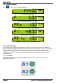
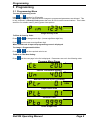
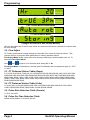
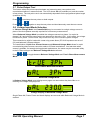
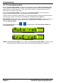
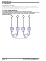
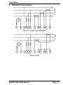
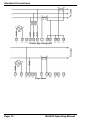
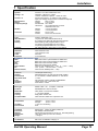
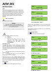
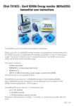
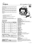
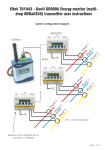
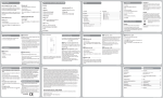
Rail350 Operating Manual January 2010 Safety 1 Safety This instruction sheet gives details of safe installation and operation of the Rail350 electricity meter. Safety may be impaired if the instructions are not followed. Labels on each meter give details of equipment ratings for safe operation. Take time to examine all labels before commencing installation. Safety symbols on the meter have specific meanings. Refer To User Manual Risk of Electric Shock WARNING The meter contains no user serviceable parts. Installation and commissioning should only be carried out by qualified personnel Further information is available at http://www.ndmeter.co.uk. Page 2 Rail350 Operating Manual Operation 2 Operation 2.1 Energy Displays Press to select kWh kvarh and Hours Run display pages. kWh Active Energy Register kVArh Reactive Energy Register rh Hours Run The Hours Run register accumulates the total time during which the average 3-phase load current exceeds a preset level. This is always displayed with a resolution of 0.1hour. The percentage level of (I1+I2+I3) at which the Hours Run register accumulates is user programmable from 1% to 100% of full scale current. Press and together and hold for 2 seconds to reset the hours run register. Scaling of the energy registers is set by the nominal input currents and voltages and remains constant during operation of the meter. Energy registers will each accumulate from zero to 99,999,999 then restart from zero. 2.2 Voltage Displays Press to select from the following displays; V Phase-n Voltages 1 - 3 V Line-Line Voltages 1 – 3 2.3 Current Displays Press to select from the following displays; A Phase 1 – 3 Current Rail350 Operating Manual Page 3 Operation 2.4 Power Displays Press to select from the following displays; kW System Active Power Frequency. Hz (Phase 1 voltage) System Power Factor (C=Capacitive) kW Phase 1-3 Active Power Phase 1-3 Power Factor (C=Capacitive) 2.5 Pulse Outputs Two isolated pulse outputs are provided for connection to external systems such as Building Energy Management Systems (BEMS), data loggers, remote counters etc. Pulse 1 is associated with the active energy (kWh) register and Pulse 2 with the reactive energy (kvarh) register. A single pulse occurs for each unit of energy on the display (eg 1 pulse per 0.1kWh). The pulse rate (amount of energy associated with each pulse) and pulse length may be set to suit the external system. 2.5.1 Pulse LEDs Light emitting diodes (LEDs) on the front panel of the instrument remain ON during each associated output pulse. Pulse Output Indicators Page 4 Rail350 Operating Manual Programming 3 Programming 3.1 Programming Menu To enter programming mode: Hold and together for 5 Seconds. A Security Code may be required before changes to programmed parameters are allowed. This is only required if a Security Code greater than zero is set via serial communications. This is then stored in non-volatile memory during power interruptions. 4-Digit Security Code To Enter A Security Code: Press or to change each digit. (Lowest significant digit first). Press to select next most significant digit. When a valid code is input the programming menu is displayed. To change a Programmable Value: Press or until the required value is set. To Move to The Next Setting: Press until the next page in the list is displayed. Parameters are set in the following order: Program Menu Pages A Current Transformer Primary V Nominal Line-Line V (or PT Primary) kWh Output Pulse Rate Pulse On Time Pulse Output Test Rail350 Operating Manual Page 5 Programming Hours Run Trip Point (Percent Amps) True 3-Phase Measurement Mode CT Auto Rotation Mode Changes Are Stored to Non-Volatile Memory After the last parameter is set the new values are stored and the meter continues to measure with the new settings. 3.2 Fine Adjust CT Primary and Nominal Voltage settings are selected from a table of preferred values. This reduces the time to program these parameters to industry standard values. Fine Adjust Mode allows values other than those provided by the default tables to be set. To enter/exit Fine Adjust Mode: Hold and together for 2 Seconds while setting CT or Un. Fine Adjust Mode is indicated by a decimal point immediately after the parameter type (ie. “CT.” or “Un.”) 3.3 CT Preferred Values Table (Amps) 5,10,15,20,30,40,50,60,75,80,100,125,150,200,250,300,400,500,600,800,1000,1200,1250,1500, 1600,2000,2400,2500,3000,3500,4000,4500,5000,5500,6000,6500,7000,7500,8000,8500,9000, 9500,10000,10500,11000,11500,12000,12500,13000,13500,14000,14500,15000,15500,16000, 16500,17000,17500,18000,18500,19000,19500,20000,20500,21000,21500,22000,22500,23000, 23500,24000,24500,25000 3.4 PT Preferred Values Table (Volts) 11,40,48,100,110,208,400,480,600,800,1000,1100,2200,3300,4000,4400,6600,7500,10000, 11000,15000,22000,25000,33000,66000,132000,220000,440000 3.5 Pulse Rate Selection Table (Counts) 1,2,5,10,100,1000 3.6 Pulse On-Time Selection Table 100ms,200ms,500ms,1s,2s,3s,5s,10s,20s Page 6 Rail350 Operating Manual Programming 3.7 Pulse Output Test This feature allows the pulse output hardware and external system connections to be commissioned without a measured load. The LCD shows Pto (off) and Ptr (run) and the number of test pulses. The test pulse rate is set automatically dependant on the programmed pulse length (maximum 0.5Hz). Press to start/stop the test pulses on both outputs. Press and together to stop the test pulses and simultaneously reset the test counter. 3.8 Voltage Input Mode Selection In “Balance Voltage Mode” the PowerRail350 may be connected to a single voltage source in place of the three phases normally required for full accuracy measurement. When Balanced Voltage Mode is enabled the voltage measured on phase 1 is copied to phases 2 & 3 and all three power-factors are assumed to be unity (1.00). In this mode, the voltage connected to phase 1 on the meter may be fed from any of the 3-Phase system voltages. This connection is valid for loads with a near unity power-factor (PF=0.95 equates to an error of 5%) and balanced 3-Phase voltages. The combination of Split Core Current Sensors and Balanced Voltage Mode allows for rapid commissioning where access cannot be made to 3-Phase terminations. At a later date when access is possible, for example during planned maintenance, the meter may be connected safely to the 3-Phase voltages and Balanced Voltage Mode de-selected. Press Mode. or to toggle between Balanced Voltage Mode and True 3-Phase Measurement True 3-Phase Measurement Mode Balanced Voltage Mode In Balance Voltage Mode some display menu pages are removed as they have little or no meaning and voltage is displayed as: V Voltage Display in Balanced Voltage Mode Single Phase kW, Power Factor and kvarh displays are removed while Balanced Voltage Mode is enabled. Rail350 Operating Manual Page 7 Programming 3.9 CT Auto Rotation Mode When “CT Auto Rotation Mode” is selected, the orientation of each Current Transformer (CT) on its respective cable becomes irrelevant. It is therefore possible to pass the cable through the centre of the CT in either direction. In this mode current direction is ignored and all power is assumed to be feeding a load (import). When “CT Auto Rotation Mode” is de-selected (“True Rotation Mode”) current direction is monitored and measurement of import and export power is provided. In both modes it is essential to place each CT on the correct phase conductor associated with the relevant phase voltage: Therefore link CT1 with V1, CT2 with V2, CT3 with V3. PowerRail350 meters are normally supplied with “CT Auto Rotation Mode” selected. In order to detect Positive and Negative power values in all four quadrants it is necessary to de-select “CT Auto Rotation Mode”. In the programming Menu Press True Rotation Mode. or to toggle between CT Auto Rotation Mode and CT Auto Rotation Mode True Rotation Mode NOTE: CT Auto Rotation Mode is not available when Balanced Voltage Mode is selected as all Power Factors are assumed to be unity and current phase and direction is ignored. Page 8 Rail350 Operating Manual Programming 4 Display Scaling The units, Wh, kWh or MWh and the position of the decimal point for the energy/power displays are automatically set dependant on the CT and Un settings for the meter. The nominal 3-phase input for the meter is defined as: Wnom = 3 x Un x CT Where: Un is the nominal Line-Line voltage or PT primary (10V - 55kV). CT is the current transformer nominal primary (10A – 25kA) Un and CT are set in programming mode. The display pages are scaled as follows: Amps Resolution CT < 80 A < 800 A < 8,000A > 8,000A Volts Resolution Un <= 90 V <= 1200 V <= 9,000 V > 9,000 V Wnom < 243 W < 2.43 kW < 24.3 kW < 243 kW < 2.43 MW < 24.3 MW < 243 MW > 243 MW Rail350 Operating Manual 0.01 A 0.1 A 1A 0.01 kA 0.01 V 0.1 V 0.001 kV 0.01 kV kW/kvar kWh/kvarh Resolution 0.1W (var) 0.1W (var) 0.001 kW (kvar) 0.01 kW (kvar) 0.1 kW (kvar) 1 kW (kvar) 0.01 MW (Mvar) 0.1 MW (Mvar) Resolution 0.001 kWh (kvarh) 0.001 kWh (kvarh) 0.01 kWh (kvarh) 0.1 kWh (kvarh) 1 kWh (kvarh) 0.01 MWh (Mvarh) 0.1 MWh (Mvarh) 1 MWh (Mvarh) Page 9 Display Scaling 5 Installation 5.1 Mounting On A Rail The Rail350 conforms to DIN 43880, 6-Module Wide. The unit is therefore compatible with a number of standard distribution systems with 45mm cut-outs. The meter should be mounted on a 35mm symmetrical (“Top-Hat”) DIN rail of minimum length 106mm. 5.2 Pulse Output Connection The pulse outputs take the form of isolated volt free normally open contact pairs. The contacts are isolated from all other circuits (2.5kV / 1minute) and at 50V from pulse1 to pulse 2. The pulses can be used as an input to a remote counter, pulse logger, building energy management system etc. Pulse Output Connections Page 10 Rail350 Operating Manual Installation 6 Standard Connections 3-Phase 3 or 4-Wire (*Optional Neutral) 3-Phase 3-Wire Rail350 Operating Manual Page 11 Standard Connections 3-Phase High Voltage (HV) Single Phase Page 12 Rail350 Operating Manual Installation 7 Specification INPUTS System Voltage Un Current In Measurement Range Frequency Range Burden Overload 3 Phase 3 or 4 Wire Unbalanced Load 400/230V. 3 Phase 3 or 4 Wire 110/63V & 208/120V optional. Others to order. 5A from external CTs. 1A optional. Fully isolated Input from Voltage Output Current Transducers Optional Voltage 50% to 120% Current 0.2% to 120% Fundamental 45 to 65Hz Harmonics Up to 30th harmonic at 50Hz Individual to the 15th Voltage <0.1VA per phase Current <0.1VA per phase Voltage x4 for 1 hour Current x40 for 0.5 second max DISPLAY Type Data Retention Format Scaling Legends Custom, Supertwist, LCD 10 years min. Stores kWh & Meter set-up 8 x 6.66mm high digits with DPs & 3.2mm legends Direct reading. User programmable CT & VT CT Primary programmable from 5A to 25kA VT primary programmable from 11V to 440kV Wh, kWh, MWh etc. depending on user settings AUXILIARY SUPPLY Standard Options Load Overload 230V 50/60 Hz ±15% 110V 50/60 Hz ±15% 2VA max. x1.2 continuous ACCURACY All errors ± 1 digit kWh kvarh kW kvar Amps & Volts PF Neutral Current Better than Class 1 per EN 62053-21 & BS 8431 Better than Class 2 per EN 62053-23 & BS 8431 Better than Class 0.25 IEC 60688 Better than Class 0.5 IEC 60688 Class 0.1 IEC 60688 (0.01In – 1.2In or 0.1Un – 1.2Un) ±0.2° (0.05In – 1.2In and 0.2Un – 1.2Un) Class 0.5 IEC 60688 (0.05In – 1.2In) PULSE OUTPUTS Function Scaling Pulse Period Rise & Fall Time Type Contacts Isolation 1 Pulse per unit of energy Settable between 1 & 1000 counts of kWh register 0.1 sec. default; Settable between 0.1 and 20 sec < 2.0ms N/O Volt free contact. Optically isolated BiFET 100mA ac/dc max., 100V ac/dc max. 2.5kV 50Hz 1 minute MODBUS® Serial Comms Bus Type Protocol Baud Rate Address Latency Command Rate RS485 2 wire + 0v. ½ Duplex, ¼ unit load MODBUS® RTU with 16 bit CRC 4800, 9600 or 19,200 User settable 1 – 247 User settable Reply within 250ms max. New command within 5ms of previous one GENERAL Temperature Humidity Environment Operating -10°C to +55°C Storage -25°C to +70°C < 75% non-condensing IP20 MECHANICAL Terminals Enclosure Material Dimensions Weight Rising Cage. 4mm2 (12 AWG) cable max. DIN 43880, 6-Modules Wide Noryl® with fire protection to UL94-V-O. Self extinguishing 106 x 90 x 58mm (Cut out 106 x 45mm) ~ 250 gms SAFETY Conforms to EN 61010-1 Installation Category III Rail350 Operating Manual Page 13