1
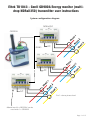
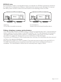
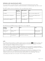
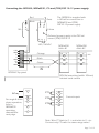
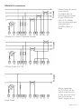
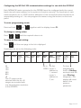
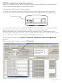
Eltek TU1043 - GenII GD900A Energy monitor (multidrop NDRail350) transmitter user instructions
System configuration diagram
NDRail350
GD900A
AC supply
240V nominal
AC
RS485
AC
AC
For 1 x three phase load
Maximum of 6 x ND350V can be
used with 1 x GD900A
Page 1 of 12
Introduction
The GD900A is part of the Eltek GenII family of transmitters.
The GD900A can be used with up to six parallel connected NDRail350 energy monitors
and appropriate current transformers, providing comprehensive monitoring and
patterns of use of multiple three phase supplies. The system is ideal for retro fit energy
monitoring. The GD900A can be used alongside all other GenII transmitter types.
(See Eltek brochure “Telemetry Energy Monitoring” on the Eltek website:
www.eltekdataloggers.co.uk/literature.shtml)
The system comprises:
" GD900A transmitter,
" Up to 6 NDRail350 monitors (1 x three phase load meter),
" NDMeter CTs (up to 18 CTs can be used per GD900A)
" DSP10-12 DIN rail mounting power supply to power the GD900A.
All components can be supplied by Eltek.
The GD900A has an input for 6 x NDRail350 energy monitors (Modbus RS485)
Each NDRail350 has an input for 1 x three phase load:
" 3 x CT (AC333mV)
" 3 x AC230V nominal
" 1 x AC230 nominal to power the unit
Parameters measured per NDRail350 are 3 x voltage, 3 x current, 3 x power factor
(cosØ), kWh and kvarh.
Page 2 of 12
GD900A channel assignment
" Channels can be presented at the RX250AL together with those from any other
GenII transmitter and can be reordered during TX Setup or when configuring the
RX250AL.
" Channels can only be renamed when configuring the RX250AL with Darca
software.
" The GD900A assumes the identity of up to 6 ‘virtual transmitters’, each of which
represents a connected NDRail350. Each virtual transmitter has its own serial
number.
" The channels of a virtual transmitter are labelled A through L.
" RX250AL channels are numbered 1 through 247.
" A fully loaded GD900A with 6 x NDRail350s connected can occupy 72 channels of
the RX250AL.
Transmitter channels for an individual NDRail350 / virtual transmitter:
Tx Channel
Phase/Range
Resolution
Function in Darca
A
V1 0-500VAC
0.1
Voltage
B
V2 0-500VAC
0.1
Voltage
C
V3 0-500VAC
0.1
Voltage
D
I1 0-1000A
0.1
Current
E
I2 0-1000A
0.1
Current
F
I3 0-1000A
0.1
Current
G
P1 0-1
0.01
Power factor (PF)
H
P2 0-1
0.01
Power factor (PF)
I
P3 0-1
0.01
Power Factor (PF)
J
65000
Pulse count kWh
K
65000
Pulse count kvarh
L
Ext power to GD900A
1
State
Page 3 of 12
Use of the GD900 with the RC250
The GD900 functions as up to 6 transmitters with consecutive serial numbers.
The RC250 can only communicate with the first transmitter in the sequence.
The first serial number can be altered using the TxSetup program. Thus, the RC250 can be
configured to receive data from the 6 consecutive virtual transmitters by changing the first serial
number using TxSetup and configuring the RC250 one transmitter at a time.
For example, if the GD900 serial number is 22001, it also has T-22002, 22003, 22004, 22005 and
22006 internally.
To configure the RC250 using the RXConfig software:
" 1. First configure the RC250 with the GD900 set to serial number 22001 to program this
serial number
" 2. Change the GD900 to serial number 22002 using TxSetup
" 3. Configure the RC250 using this serial number to program it
" 4. Repeat steps 2 and 3 for serial numbers 22003, 22004, 22005 and 22006
" 5. Change the GD900 serial number back to 22001
CTs that can be used with the NDRail350 (all AC330mV output at range)
Type
Range
Size mm
Cable
dia
SCL8-5
SCL16-50
SCL16-100
0-5A
0-50A
0-100A
43 x 37 x 32
51 x 45 x 27
51 x 45 x 27
8mm
16mm
16mm
SCT19-150
0-150A
51 x 53 x17
19mm
SCT32-400
0-400A
82.5 x 85 x 27
32mm
SCT51-800
0-800A
121 x 127 x 32
51mm
CT open
CT closed
Other SCT19 models available: 5, 10, 15, 20, 30, 50, 70 and 100A - refer Eltek
Other SCT32 models available: 70, 100, 150, 200, 250, 300, 400 and 600A - refer Eltek
Other SCT51 models available: 600, 1000A - refer Eltek
SCL can be operated at range x 1.21 continuously
SCT can be operated at range x 1.31 continuously
Important note:
CTs have a moulded arrow impressed on the case, the CT must be mounted on the power cable
so that the arrow points to the load!
CT wiring : Black is positive, White is negative.
Page 4 of 12
GD900A Links
The transmitter contains a rechargeable battery to maintain the GD900A operational should the
AC supply fail. For despatch the battery is disconnected (to prevent total discharge). To connect
the battery when received, remove the two bottom cover retaining screws to reveal:
Battery
Shipping;
The red link is installed as shown..
Battery
To commission:
Remove the red link and install as above
Battery charging, recovery and endurance
The PCB mounted 150mAh 6V NiMh battery is charged at approximately 4mA. A fully discharged
battery requires 36 hours charge to reach 80% capacity. The TX is fully functional if the battery is
discharged when external power is applied. A charged battery can provide 24 hours standby
should the AC supply fail. Settings are not lost if the battery is fully discharged.
The battery is PCB mounted. Should replacement be necessary, the transmitter must be returned
to Eltek or our approved distributor.
External power required is 12VDC regulated. The preferred power supply is the type DSP10-12.
This DIN rail mounting power supply is provided with screw down connections for ease of
installation. The max demand current from the external power supply is 50mA.
Page 5 of 12
Indicators and concealed push switch
The push switch is located behind a small access hole located at the rear of the
transmitter. To activate the switch a small screwdriver or unfurled paper clip can be used.
Red LED cadence due to activation of the concealed push switch:
Function
Activate
switch for
LED cadence
LCD
Tx disable
5 seconds
5 x fast flashes
After 5 seconds displays OFF
Tx enable (when configured)
5 seconds
1 continuous 5
sec flash
After 5 seconds displays sensor
information
Test transmissions approximately
every 5 sec for 2 minutes.
2 second
Short flash at time No change
of transmission
Red LED due to GD900A being configured or not configured:
GD900A
condition
LED
GD900A not
configured
“Blink” every 8
seconds
GD900A configured Short flash at time of
a transmission
Note
LCD
Battery gauge
displayed only
A transmission occurs at a random time
within the set TX interval
See Display below
LCD
The LCD includes a battery condition gauge active at all times:
(Battery gauge will
flash if battery discharge imminent). Only configured channels are displayed. The LCD
scrolls through the configured channel values.
If channels A-K are configured but the NDRail350 is not connected or communications
have failed, the display will read “OPEN”. If channel L is configured, this display will read 0 if
no external supply is connected or 1 if external 12VDC is connected.
Note: If the GD900A is to be stored or will not be connected to a charging source for
more than 48 hours, the GB90A should be disabled (put into hibernate mode, i.e. TX
disable mode) to prevent total battery drain and possible loss of settings. Press the
concealed push switch for 5 seconds. The LCD will now read OFF.
Page 6 of 12
Connecting the GD900A, NDRail350, CTs and (TDK) DSP 10-12 power supply:
Red
The GD900A is supplied with
a 1M tail for connection to
NDRail350 and (TDK)
DSP10-12 power supply.
Twist
Black
V-
V+
1M
10mm
E N L
Preferred power supply is the DIN rail
mount (TDK) DSP10-12
100 / 240VAC
+12V
GND
T+
TGND
R+
RGND
NDRail350
Addr. #1
NDRail350
Addr. #2
Orange
15
A
15
A
Black
16
B
16
B
Green
17
0V
17
0V
etc.
1M
GD900A Top panel
DIN Rail mounting (width 105mm)
Isolated serial comms
1
L
CT1
AC
For single & three
phase operation,
refer to
NDRail350
operating
manual/refer
next page.
2
N
3
Vn
4
V1
CT2
CT3
5
V2
6
V3
7
I1+
8
I1-
9
I2+
10
I2-
11
I3+
12
I3-
Current inputs
Note: Wire CT black to I1+ and white to I1- etc.
Connect only CTs with the same range value!
Page 7 of 12
NDRail350 connections
Ensure fuses are wired
in as shown!
A suitable Din rail
mounting fuse holder
is type CSFL4U (for
fuse 1A 5 x 20mm
fuse, not included) and
end plate type
CSFLEPU. Refer to
Eltek.
3-Phase 3 or 4 wire (*Optional Neutral)
3-Phase 3 wire (2 x CTs)
Single Phase
Where applicable
V1(4), V2 (5), V3 (6)
can be linked to L(1).
A fuse must be used
(see note above)
from L supply to L(1)
Page 8 of 12
Configuring the ND Rail 350 communications settings for use with the GD900A
Each NDRail350 meter connected to the GD900A must be configured with the correct
baud rate and meter address for the system to function correctly. The baud rate of each
meter should be set to 19200 and the addresses of the connected meters should be set
sequentially starting at 1. You can program the meters using the buttons on the front
panel.
To enter programming mode:
I
Press and hold
and
V
together until the display shows Ct
To change a setting value:
Press
P
or
E
until the required value is set.
To move to the next setting:
Press
I
until the next page in the list is displayed.
Parameters are set in the following order:
Ct
Un
PLr
PLt
Pto
Hr
br
Addr
trUE
Auto
Storing
current
voltage
pulse
output
rate
pulse
on time
pulse
test
hours
run
baud
rate
meter
address
voltage
input
mode
CT auto
rotation
mode
store
setup
5
50
100
150
400
800
The CT range can be
selected from this list. All
ranges are recorded with
one decimal place resolution
in the GD900A.
set to set first
19200. meter’s
address to
1, second
meter’s
address to
2, etc.
To close
programming,
scroll to Storing
and wait until the
word Storing
disappears. The
display will revert
back to the
previous
parameter.
Page 9 of 12
GD900A configuration using Darca software
Refer to the Quick start guide (ref TU1008) supplied with the RX250Al or download from
http://www.eltekdataloggers.co.uk/literature.shtml.
Connect the LCTX3 to the “Comms” socket:
To access the Comms connector, remove the two screws securing the case bottom to
reveal the Comms connector. (Note GD900A cannot be configured by the logger only).
Comms connector
As a precaution disconnect the external 12VDC power supply before inserting the LCTX3
jack into the comms socket. The external 12VDC can now be connected.
When configuration is completed disconnect the external 12VDC power supply before
removing the LCTX3 jack. If the unit is not intended for immediate use, park the battery link
so as to disconnect the internal battery. (See GD900A links page 4)
Launch Darca and open the Squirrel Channel to Transmitter Channel Assignments
window.
Before setting the Tx channels set the TX Interval:
Page 10 of 12
GD900A method of operation
Sampling the meters
The GD900A reads and stores the values from the NDRail350 meter(s) every 10 seconds.
It waits 1 second between reading each connected meter. 17 sets of values per meter are
stored and a rolling average is kept. To check the system is operating correctly, you can
verify that this is happening by watching the Cmd light on the front of the NDRail350
meters.
Transmitting the data
At each transmission the GD900A transmits the average of the 17 values for voltage,
current and power factor. The actual transmission time of the virtual transmitters begins at
a random point of time within the transmission interval. The virtual transmitters 1 through
6 (or as many are configured) will transmit in order, each transmission 1 second apart after
the transmission time of the first virtual transmitter. The default TX interval is preset to 5
minutes but can be altered as required.
A note about ‘Virtual Transmitters’
For ease of use, The multiple ND Rail 350 meters connected to a GD900A transmitter will
appear as a series of ‘virtual transmitters’ in Darca (and are treated as such by the
receiver/logger). Each virtual transmitter will have its own serial number. These virtual
transmitter serial numbers run sequentially starting with the GD900A’s serial number. For
example:
GD900A serial number: 20001
ND350 address 1: virtual transmitter serial number: 20001
ND350 address 2: virtual transmitter serial number: 20002
ND350 address 3: virtual transmitter serial number: 20003
ND350 address 4: virtual transmitter serial number: 20004...etc.
After configuring the transmitter channels for the first NDRail350 in Darca’s Squirrel
Channel to Transmitter Channel Assignments window, you can move to the next
connected meter in the list by clicking Next V Tx (Next virtual transmitter). The next meter
can then be configured in the same way. To move back to the previous meter in the list,
use << Prev V Tx (previous virtual transmitter).
Configuring a virtual transmitter
" For Tx channels A to L: select only the channel range from the drop down as shown in
the screen shot and click on Set Channel. DO NOT ATTEMPT to use the Edit EU
Range box.
" Channels D, E and F are fixed 0-1000A; ensure the range type setting on the
NDRail350 matches the range of the connected CT. See operating manual.
" Channel L monitors connection of the external power supply: 0 = not connected and
1 = 12V connected. Darca Plus can use these values to set an alarm should the AC
supply fail. Channel L is configurable per virtual transmitter. To avoid transmitting
unnecessary data configure Channel L for the first virtual transmitter only.
" Device Type should always be set to A20.
Page 11 of 12
GD900A specification
Frequency:
Default is 434.225Mhz (other frequencies are available)
Tx compliance:
To EN300 220 -1
Tx output power:
10mW ERP
Useable Tx interval:
typically 10 seconds to 15 minutes
On air duration:
approximately 400mS
Environment:
Indoor only, rated IP40
Temperature Range:
-10 to +55ºC compliant to EN300 220-1, operational -30 to +60ºC
Humidity:
95% non condensing
Size:
85mm x 78mm x 42mm (excluding 75mm antenna)
Weight:
250g
Connection strip:
8 x miniature pitch rising cage connector (included)
Antenna:
Supplied compressed spring, L=75mm, Gain -3db
Antenna connector:
SMA
Fixing:
WBG wall fixing bracket (optional)
Battery type:
PCB mounted (6V) 0.17Ah Ni-mH
Battery endurance:
typically >24 hours if battery fully charged
Charging time:
typically 36 hours from discharged to 80% capacity
Max lead length to ND Rail350V (screened twisted pair): <20M
NDRail350 support information
Brochure: http://www.ndmeter.co.uk/files/ND_350V_Retro-Fit_Meter_Brochure.pdf
User manual: http://www.ndmeter.co.uk/files/ND_PowerRail350_Manual.pdf
Installation manual: packed with product
SCL CT brochure: http://www.ndmeter.co.uk/files/SCL_Retro-fit_Current_Sensors.pdf
SCT CT brochure: http://www.ndmeter.co.uk/files/SCT_Retro-fit_Current_Sensors.pdf
Specialist Data Loggers
Eltek Ltd, 35 Barton Road, Haslingfield
Cambridge, CB23 1LL, England
Tel: +44 (0) 1223 872111
Fax: +44 (0) 1223 872521
email: [email protected]
http://www.eltekdataloggers.co.uk
TU1043 03/11/15
Page 12 of 12
![Manual 08 [colour match]](http://vs1.manualzilla.com/store/data/006024659_1-3bda8edcd573634c82e14bf074c48937-150x150.png)