1
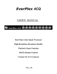
EverPlex 4CDX
User’s Manual
and
Operation Instructions
Version 1.0
Table of Content
Notice................................................................................................................. 1
Safety Warning................................................................................................... 2
Introduction ....................................................................................................... 3
Specification....................................................................................................... 4
Chapter I
Systems Connection ................................................................. 5
Chapter II Functional Setting..................................................................... 6
1.
2.
3.
4.
5.
6.
7.
Set
........................................................................................................6
Date, time, and on screen display setting..........................................................7
Alarm records display.......................................................................................8
Video menu… … … ...........................................................................................9
Title menu ......................................................................................................10
Sequential switch menu .................................................................................11
Alarm setting menu .......................................................................................12
Chapter III
Front Panel Keypads............................................................. 13
1.
2.
3.
4.
Power key ......................................................................................................13
Full screen select key .....................................................................................13
Freeze screen select key..................................................................................14
Function key ..................................................................................................14
4.1 Set
.....................................................................................................14
4.2 Buzzer.....................................................................................................14
4.3 Alarm ......................................................................................................15
4.4 Lock ......................................................................................................15
5. Video key ......................................................................................................16
5.1 Quad screen select key ............................................................................16
5.2 Auto sequential switching key.................................................................16
5.3 VCR playback key ..................................................................................17
5.4 VCR pass through...................................................................................17
5.5 VCR playback zoom key.........................................................................18
Chapter IV
Back Panel Connection.......................................................... 19
1. BNC Connectors ............................................................................................19
1.1 Monitor ......................................................................................................19
1.2 VCR out .....................................................................................................19
1.3 VCR in ......................................................................................................19
1.4 Video in......................................................................................................19
1.5 Video out....................................................................................................19
2. Power
......................................................................................................20
3. Alarm Connectors (DB-15) ............................................................................20
3.1 Alarm out ...................................................................................................21
3.1.1 Normally open connection...................................................................21
3.1.2 Normally closed connection.................................................................21
3.2 Alarm in and alarm reset ............................................................................22
3.2.1 Alarm in...............................................................................................22
3.2.2 Alarm reset...........................................................................................23
4. Time Lapse Recording....................................................................................23
5. RS232 Connector ...........................................................................................24
5.1 The pin assignment of the 9 pin D-SUB connector....................................24
5.2 Transmission setting...................................................................................25
5.3 Remote control protocol.............................................................................25
5.4 Alarm message sent via RS232..................................................................26
6. Terminator ............................................................................... 26
EverFocus Electronics Corp.
1
Notice
This manual is presented to the users of EverPlex 4CDX by EverFocus
Electronics Corp. With years of engineering researches, EverFocus has
spared no effort to provide the high quality products to the worldwide
users. For the policy of continual product improvement, EverFocus
reserves the right to make changes to the product specifications and
documentation without notice. All the components of the products,
including accessories, components, and outlook, are based on the
agreements of each deals to satisfy all kinds of users. Meanwhile,
please be advised that every step of operation must follow the
instruction of this manual to keep EverPlex 4CDX working under the
best condition. Please notice that EverFocus will not be charged any
claims or renewing cases resulted from inappropriate operation.
EverFocus Electronics Corp.
2
Safety Warning
1.
To prevent fire or shock hazard, do not expose this equipment to the
environment of high humidity and dust. Do not use it in an unprotected
outdoor installation or any area classified as a wet area.
2.
Installation environment: The temperature should be kept between 0oC ~
+50oC
3.
For safety sake, do not disseminate the unit or put it on an unstable base.
4.
Ventilation: Openings in the enclosure are provided for ventilation and to
ensure reliable operation of the unit and to protect it from overheating. These
openings must not be blocked or covered. This unit should not be placed in a
built-in installation unless proper ventilation is provided.
5.
Cleanse: Unplug the unit from the outlet before cleansing. Do not use liquid
cleaners or aerosol cleaners. Use a damp cloth to clean it.
6.
Overload: Do not overload outlets and extension cords as this may result in a
risk of fire or electric shock.
7.
Power-cord Protection: Power-supply cords should be routed so that they are
not likely to be walked on or pinched by items placed upon or against them,
paying particular attention to cords at plugs, convenience receptacles, and the
point where they exit from the appliance.
8.
Object and Liquid Entry: Never push objects of any kind into this unit through
openings as they may touch dangerous voltage points or short-out parts that
could result in a fire or electric shock. Never spill liquid of any kind on the
unit.
9.
Service: Do not attempt to service this unit yourself as opening or removing
covers may expose you to dangerous voltage of other hazards. Refer all
servicing to qualified service personnel.
10.
EverFocus Electronics Corp.
In order to prevent the electric shock, please notice the
cautious sign and do not directly contact with the
connectors.
3
Introduction
EverPlex 4CDX, a real time color Duplex Multiplexer, is the best choice for 4
cameras multiple monitoring and recording. The video inputs and outputs are
digitally processed and stored as consecutive fields on video tape. The multiplexer
allows simultaneously viewing VCR playback, 4 camera inputs in quad, and alarm
channel display via 3 monitor outputs.
Main Features:
? Full capability duplex multiplexer with simultaneously multiple monitoring.
? Connect up to 4 cameras with loop through.
? High Resolution 720 x 480 (NTSC), 720 x 576 (PAL).
? Superior quality display and 16 million true colors.
? Alarm and video loss detection.
? Independent brightness, contrast, color and tint adjustments for each channel.
? Programmable auto sequential switching function and adjustable dwelling
time (from 1 to 99 seconds).
? Built-in timer and title generator.
? Alarm input with built-in buzzer.
? Alarm records display contains up to 5 records.
? Selectable time-lapse recording mode.
? VCR playback in Quad or Full screen image.
? VCR playback zoom in full screen for detail images.
? VCR pass through.
? RS232 remote control.
? Rack mount 1U size.
? User-friendly front panel design.
EverFocus Electronics Corp.
4
Specification
Video format:
NTSC or PAL
Video input:
4 cameras inputs, 1V p-p/75 ohm, with loop through
1 VCR input, 1V p-p/75 ohm
Video output:
4 video outputs, 1V p-p/75 ohm
Monitor output:
3 monitor outputs (1V p-p/75 ohm)
Recording output:
Multiplexed video output, 1V p-p/75 ohm
Refresh rate:
60 fields/sec. (NTSC), 50 fields/sec. (PAL)
Resolution:
720 x 480 (NTSC), 720 x 576 (PAL)
VCR playback:
Yes
Playback zoom:
Yes
Video freeze:
Yes
Video loss detection:
Yes
Time-Lapse record:
Selectable time-lapse recording mode
Alarm input:
4 alarm inputs and 1 alarm reset input
Alarm output:
1 Normally Open, 1 Normally Closed relay output
Buzzer:
Title:
Yes
6 characters title generator for each camera input
Timer:
Built-in real time clock
Setup:
On screen setup
Switching:
Programmable auto sequential switch and adjustable
dwelling time (1-99 sec.)
Key lock:
Yes
Remote control:
Power source:
D-Sub 9 pins / RS232
AC 95 ~ 260V 50/60 Hz
Power consumption:
Dimension:
17W max.
438 x 262 x 44 mm
Weight:
5 Kg.
EverFocus Electronics Corp.
5
Chapter I Systems Connection
Main Monitor
VCR
1
FULL SCREEN
2
3
4
1
FREEZE
2
3
4
FUNCTION
SET
BZ
AL
VIDEO
LOCK
Zoom
SEQ
POWER
EverPlex 4CDX
+ -
NEXT P. DEFAULT
Live Quad
Monitor
The System Connection
Call Monitor
of
EverPlex 4CDX
EverFocus Electronics Corp.
5
Chapter I Systems Connection
Main Monitor
VCR
1
FULL SCREEN
2
3
4
1
FREEZE
2
3
4
FUNCTION
SET
BZ
AL
VIDEO
LOCK
Zoom
SEQ
POWER
EverPlex 4CDX
+ -
NEXT P. DEFAULT
Live Quad
Monitor
The System Connection
Call Monitor
of
EverPlex 4CDX
EverFocus Electronics Corp.
6
Chapter II Functional Setting
SET
1. Set
Press the SET key to set time/date, title on/off, picture, camera titles, switching
sequence, switching dwell time, alarm sensor type, alarm hold time, and display
the alarm/video loss records.
There are 6 pages in the setting mode :
Page
Page
Page
Page
Page
Page
1:
2:
3:
4:
5:
6:
Date, time setting and on screen display on/off setting
Alarm records display
Set brightness, contrast, color, and tint for camera 1~4
Set channel title for camera 1~4
Set auto sequential switching on/off and switching dwell time
Set alarm sensor type, alarm hold time, and buzzer on/off
Keys for setting are as below:
Press Next P. to select the following pages
for setting.
NEXT P.
Press Default key to reset the setting.
DEFAULT
Press the +/- keys to set the value.
+
1
2
3
4
Press the cursor key to select the item for
setting.
EverFocus Electronics Corp.
7
2. Date, time, and on screen display setting
DATE:
TIME:
1997-01-01
01:01:01
RECORD OUT
RECORD OUT
RECORD OUT
DATE: ON
TIME: ON
TITLE: ON
LIVE SCREEN DATE: ON
LIVE SCREEN TIME: ON
LIVE SCREEN TITLE: ON
TIME LAPSE
RECORD: EXT
DATE - data format is CCYY-MM-DD, where
CC : Century code from 19 to 20
MM : Month data from 01 to 12
TIME - data format is HH:MM:SS, where
HH : Hour data from 00 to 23
SS : Second data from 00 to 59
YY: Year data from 00 to 99
DD: Day data from 01 to 31
MM: Minute data from 00 to 59
On Screen Display Setting
RECORD OUT DATE, TIME, TITLE : ON/OFF
‘ON’: The date, time, and title will be recorded in VCR.
‘OFF’: The date, time, and title will not be recorded in VCR.
LIVE SCREEN DATE, TIME, TITLE : ON/OFF
‘ON’ :Date, time, and title will show on the monitor display.
‘OFF’:Date, time, and title will not show on the monitor display.
TIME-LAPSE RECORD
‘12HR,24HR,… 960HR’:
The recording mode must be set before recording the video inputs. The recording
hours can be set from 12 hours, 24hours,… to 960 hours. After the mode is set,
please kindly test the recording function to ensure all the video inputs of the required
channel are recorded without any loss.
‘EXT’: When using the step signal cable, the system will automatically detect the clock from
the external VCR. If the step signal cable can not be detected, the system will keep
the status of continuous recording.
Keys for setting are as below:
Press Next P. to select next page for alarm
records display.
NEXT P.
Press the +/- keys to correct setting value
+
1
2
3
4
Press the cursor key to select the items on the
same page for setting.
EverFocus Electronics Corp.
8
3. Alarm records display
C A
ALARM
DATE
RECORDS
TIME
4 S
1998-11-24 10:00:00
The Alarm Record format is : ( C
A
DATE
TIME )
C : The channel number from 1 to 4 which receives the alarm inputs.
A : Indicate where the alarm happened: ‘S ‘ - alarm from sensor input
‘V‘ - alarm from video loss detection
DATE, TIME - Indicate the date and time when the alarm happens
The memory of the Alarm Records Display contains up to the latest 5 records.
Keys for setting are as below:
Press Next P. key to the setting page of video menu.
NEXT P.
DEFAULT
EverFocus Electronics Corp.
To clear the alarm records, please press Default key.
It will clear all the records at one time.
9
4. Video menu
BRIGHT: 32
CONTRAST:27
COLOR:
31
TINT:
32
BRIGHT: 32
CONTRAST:27
COLOR:
31
TINT:
32
BRIGHT: 32
CONTRAST:27
COLOR:
31
TINT:
32
BRIGHT: 32
CONTRAST:27
COLOR:
31
TINT:
32
The numbers for setting the value of brightness, contrast,
color and tint for each channel are: 00~63
Keys for setting are as below:
Press Next P. to the next page of title menu.
NEXT P.
Press the +/- keys to set the value.
+
1
2
3
4
Press the cursor key to select the items on the same
page for setting.
EverFocus Electronics Corp.
10
5. Title menu
CH1:
CH2:
CH3:
CH4:
CH1
CH2
CH3
CH4
The characters for setting the title of each channel are:
“A~Z”, “a~z”,“Space”, “.”, “-”, “:”, “0~9”
Keys for setting are as below:
Press Next P. to the sequential switch menu.
NEXT P.
1
2
3
EverFocus Electronics Corp.
4
Press the cursor key to select the characters and
items on the same page for setting.
11
6. Sequential switch menu
SEQUENTIAL
MENU
CH1:
CH2:
CH3:
CH4:
QUAD:
SWITCH
ON
ON
ON
ON
ON
SWITCH TIME
SEC
:
03
REFRESH MODE :
FIELD
CH1 - CH4 : ON/OFF
‘ON’ : The camera is set in the corresponding channel in the auto sequential switching
mode.
‘OFF’ : The camera is not set in the corresponding channel in the auto sequential
switching mode.
To cancel the auto sequential screen display, you can either Set CH1 - CH4 ‘OFF’at the
same time or press any one of the full screen camera select key.
QUAD: ON/OFF
‘ON’ : The quad screen display is under the auto sequential switching mode.
‘OFF’ : The quad screen display is not under the auto sequential switching mode.
SWITCH TIME: The auto sequential dwelling time for the video inputs of each camera
can be set from 0-99 seconds. The required switching time must be
set before the sequential switch is used.
REFRESH MODE: FIELD/FRAME
‘FIELD’ : The speed of capturing the video inputs is 60 fields per second.
‘FRAME’:The speed of capturing the video inputs is 30 frame per second.
Keys for setting are as below:
Press Next P. to the alarm setting menu.
NEXT P.
Press the +/- keys to set switch time, refresh mode,
and sequential switching mode for each camera.
+
1
2
3
4
Press the cursor key to select the item on the same
page for setting.
EverFocus Electronics Corp.
12
7. Alarm setting menu
ALARM SETTING MENU
CH
1
2
3
4
SENSOR
N.O.
N.O.
N.O.
N.O.
ALARM RESET IN : N.O.
ALARM HOLD TIME: 05 SEC
There are two types of alarm sensor inputs, one is normally open and the other is normally
closed.
CH1 - CH4 : N.O./ N.C.
'N.O.': The normal situation of sensor inputs is set normally opened. If the inputs are closed,
the system will start the alarm.
'N.C. : The normal situation of sensor inputs is set normally closed. If the inputs are opened,
the system will start the alarm. Closed means to short the alarm signal line to the
ground.
ALARM RESET IN : To set alarm reset input type as 'N.O.' or 'N.C.'
ALARM HOLD TIME : Indicate the alarm time duration (0~99 seconds), the system will
display the alarming channel for the programmed time in full
screen of alarming channel on the main monitor and call monitor.
Keys for setting are as below:
Press Next P. to go back to the first setting page.
NEXT P.
Press the +/- keys to set the value.
+
1
2
3
EverFocus Electronics Corp.
4
Press the full screen cursor key to select the items
on the same page for setting.
13
Chapter III Front Panel Keypads
POWER
1. Power key
ON: Turn on the machine.
OFF: Turn off the machine.
FULL SCREEN
1
2
3
4
2. Full screen select key
Press any key of FULL SCREEN, the picture of the corresponding channel will fill the
whole screen of the monitor. These function keys are available in Live display and VCR
playback mode.
FULL SCREEN
1
2
3
4
LED ON: Press any one of the camera select key, the picture of the
corresponding channel fill the whole screen on monitor
display.
FULL SCREEN
1
2
3
4
LED OFF: When all the LEDs of the full screen are off, there is a quad
image on the monitor display.
EverFocus Electronics Corp.
14
FREEZE
1
2
3
4
3. Freeze screen select key
In live quad display mode, press the individual freeze key to freeze the required channel.
The title of the frozen channel will blink. Press the same key will make the pictures live
again. In VCR playback mode, the Freeze function can be further practiced in both quad
and full screen display. Press any key of Freeze, the pictures on the screen will all be
frozen. Press the same key again, the system will go back to the normal VCR playback.
FREEZE
1
2
3
4
LED ON: The picture of the corresponding channel is frozen.
FREEZE
1
2
3
4
LED OFF: The picture of the corresponding channel is not frozen.
FUNCTION
SET
BZ
ALARM LOCK
4. Function key
SET
4.1 SET
Press SET key to program the function in the setting menu.
SET
LED ON: The system is in the setting mode.
SET
LED OFF: The system is not in the setting mode.
BZ
4.2 BUZZER
Press the BZ key to turn on/off the buzzer. The buzzing time is as the same as alarm
hold time.
BZ
LED ON: It will buzz when alarm happens.
BZ
LED OFF: It will not buzz when alarm happens.
EverFocus Electronics Corp.
15
ALARM
4.3 ALARM
Press ALARM key, the machine will start the alarm system and to send the
alarm signals.
ALARM
LED ON: The alarm systems is started.
ALARM
LED OFF: The alarm systems is not started.
LOCK
4.4 LOCK
Press and hold the LOCK key over 3 seconds to lock the function keys of the front
panel. Press and hold the LOCK key again over 3 seconds will unlock the function
keys of the front panel.
LOCK
LOCK
LED ON: Except LOCK key, all the function keys of the front panel are
locked to avoid unexpected contact with the panel.
LED OFF: No keys is locked.
EverFocus Electronics Corp.
16
VIDEO
ZOOM
5. Video key
SEQ
5.1 Quad screen select key
Either in live display or in VCR playback mode, it is optional to set the video inputs
as quad or full screen. Press the Quad screen select key, the images of the four
cameras will be displayed in a quad page.
LED ON: The quad image is displayed on the screen.
LED OFF: The full screen image is displayed on the main monitor.
SEQ
5.2 Auto sequential switching key
Press SEQ key the systems will enter the auto sequential switching mode, the sequence
of switching is optional and programmable in setting menu. The camera inputs will be
sequentially displayed in full screen and live quad on the main monitor according to the
setting. Press the SEQ key again, it will exit the auto sequential mode and stay at the
last picture displayed on the screen. Or press full screen camera selecting key (1,2,3,4),
it will also exit the auto sequential mode and stay at the full screen of the corresponding
channel you select.
SEQ
LED ON: Auto sequential switching mode is on.
SEQ
LED OFF: Auto sequential switching mode is off.
EverFocus Electronics Corp.
17
5.3 VCR playback key
Freeze SEQ
Set
Press the VCR playback key will enter the 2playback mode and display the recorded
video inputs in quad page. Press the full screen camera corespondent key will display
the full screen of the chosen channel. Press the quad corespondent key, the systems will
turn to the quad page in VCR playback mode. In order to exit the VCR playback mode,
press the VCR playback key again will go back to the live display.
LED ON: The system is displaying the recorded video from VCR.
FULL SCREEN
1
2
3
4
LED ON: The system is displaying the recorded video of the
corresponding channel from VCR in full page.
LED OFF: The system is not displaying the recorded video in VCR.
SEQ
5.4 VCR pass through
Under the VCR playback mode, press the sequential switch key, “SEQ”. The VCR
pass through mode will be started and can be used to directly view the VCR’s output
for adjusting tracking or verifying proper VCR connections to the EverPlex 4CDX.
Press the sequential switch key again, the systems will go back to the VCR playback
mode.
SEQ
LED ON: The mode of VCR pass through is started.
SEQ
LED OFF: The system is in normal VCR playback mode.
EverFocus Electronics Corp.
18
ZOOM
5.5 VCR playback zoom key
1
The VCR playback zoom key is a breakthrough function which provides users to zoom
in and show the further detail image on the screen while viewing video playback.
Choose the required full page in the VCR playback mode, then press the VCR zoom
key, it will focus on the center of the screen to 4 times enlarged the original image.
According to the monitor display, press the function cursor key to focus on any
required image. Finally, press the VCR zoom key again will go back to the full screen
display in VCR playback mode.
ZOOM
LED ON: The VCR playback zoom function is practicing.
FUNCTION
SET
BZ
ALARM LOCK
Press the function cursor key to move the zoom area to the
required image.
ZOOM
1
EverFocus Electronics Corp.
LED OFF: The VCR playback zoom function is not practicing.
19
Chapter IV Back Panel Connection
OUT
POWER
VCR
1
2
IN
3
4
IN
OUT
MONITOR
CALL
MAIN
QUAD
TERMINATOR
ON
OFF
RS232
ALARM
1. BNC Connectors
1.1
Monitor
There are three monitor outputs: “Quad”, “Call Monitor”, and “Main Monitor”.
Each of them can be connected with the other devices of monitors:
Main Monitor: This connector is used for Main Monitor display. There will be
full page, quad page, or playback video images displayed on the main monitor.
Call Monitor: This connector is used for Call Monitor. There will be alarming
channel displayed in full screen on the call monitor. If there are
over two channels deliver the alarm or video loss signals in the
same time, all of the alarming channels will be displayed in full
pages in turns on the screen at the call monitor. The time for
displaying the alarming channel can be programmed in the setting
menu.
Quad: This connector is used for the Quad Monitor display. Only live quad will
be displayed on the quad monitor.
1.2
VCR Out
Connect this output port to the VCR input. The multiplexed video outputs will be
stored as consecutive fields in video tape.
1.3
VCR In
Connect this input port to the VCR output.
1.4
Video In
The connectors of video inputs enable to receive the signals from each cameras
through the 75 ohm coaxial cables.
1.5
Video Out
Connect the other devices with these connectors which are used to loop through
the camera outputs to the other devices.
EverFocus Electronics Corp.
20
2. Power
This device can be used under AC 90 ~ 260V (50 / 60 Hz) power source.
8
1
3. Alarm Connectors (DB-15)
15
PIN #
1
2
3
4
5
6
7
8
NAME
Relay Common contact
Relay Normally Open contact
Relay Normally Closed contact
GROUND
ALARM IN 4
ALARM IN 3
ALARM IN 2
ALARM IN 1
EverFocus Electronics Corp.
PIN #
9
10
11
12
13
14
15
9
NAME
STEP signal in from VCR
NC
Alarm Reset
NC
NC
NC
NC
21
3.1 Alarm out
There are two ways to do the alarm out connection:
3.1.1 Normally open connection (use pin # 1 and # 2)
2
8
RELAY
COIL
9
15
To external
equipment
1
EverPlex 4CDX
3.1.2 Normally Closed Connection (use pin # 1 and # 3)
2
8
15
9
EverPlex 4CDX
EverFocus Electronics Corp.
RELAY
COIL
To external
equipment
1
22
3.2 Alarm in and alarm reset
There are 4 alarm sensors in for 4 channels and 1 alarm reset in, all these
5 alarm inputs can be set to Normally Open or Normally Closed by user.
ALARM
CIRCUIT
SENSOR 1
SENSOR 2
SENSOR 3
SENSOR 4
8
15
ALARM RESET
2 1
9
EverPlex 4CDX
3.2.1 Alarm in
There are four alarm inputs. Please connect the alarm input in the same sequence as the
cameras input BNC.
When any alarm signal comes in, the EverPlex 4CDX will do the following:
1. switch to the full screen display of the alarm channel and show in call
monitor.
2. blink the channel ID with alarm message.
3. turn on the buzzer if the buzzer setting is on.
When more alarms come up in the alarming status, the main monitor will switch to quad
display to show all the channels where alarms happened.
The ALARM in can be selected as normally open input or normally closed input:
Normally Open : I f the alarm input is selected as Normally Open input, then the
(N.O.)
input is opened normally, and shorted to the ground means an alarm
happens.
Normally Close : If the alarm input is selected as Normally Close input, then the
(N.C.)
input is shored to the ground normally, and opened input means an
alarm happens.
EverFocus Electronics Corp.
23
3.2.2 Alarm reset
External alarm reset signal used to reset the alarm and turn the buzzer off. If it is selected
as Normally Closed input, then the input is shorted to the ground normally. It will be
opened when an alarm reset signal comes in. If it is selected as Normally Open input, then
the input is opened normally. It will be shorted to the ground when an alarm reset signal
comes in.
4. Time Lapse Recording
1. When the time-lapse recording mode is set from 12 hours to 960 hours:
Please be advised that the recording mode of EverPlex 4CDX must be programmed according
to your VCR recording mode. If the recording modes from both devises are different, the
system will only rely on the setting of EverPlex 4CDX. For example, if the recording mode
of EverPlex 4CDX is set as 12 hours, but VCR is set as 24 hours, the systems will record the
video inputs under the recording mode of 12 hours. In the other hands, the appropriate
operation should be set as 24 hours for the recording mode of EverPlex 4CDX as the same as
the one of your VCR.
2. When the time-lapse recording mode is set as “EXT” in the setting menu:
EverPlex 4CDX will automatically detect the step signal from the VCR. If there is no step
signal detected, the systems will go back to the status of continuous recording.
CH1
24HR
The message of recording mode is showed
upon the programmed time-lapse recording
mode of EverPlex 4CDX.
1999-01-01
01:06:08
CH1
When the systems is in the status of continuous
recording, there is no message of recording
mode.
1999-01-01
EverFocus Electronics Corp.
01:06:08
24
5. RS232 Connection
EverPlex 4CDX may be controlled by a computer or a terminal via the standard 9 pin
D- sub/RS232 connector, which is connected to the alarm I/O by a cable with 9 pin
and 9 pin connectors. EverPlex 4CDX will send the alarm message to the host via
RS232 when any alarm occurs.
OUT
VCR
1
2
3
4
IN
IN
POWER
OUT
MONITOR
CALL
MAIN
QUAD
TERMINATOR
ON
OFF
RS232
ALARM
9-PIN MALE
CONNECTOR
5
1
9-PIN D-SUB
CONNECTOR
9
6
5.1 The pin assignment of the 9 pin D-SUB connector
EverPlex 4CDX
PIN #
1
2
3
4
5
6
7
8
9
NAME
NOT CONNECTED
TXD
RXD
NOT CONNECTED
GROUND
NOT CONNECTED
NOT CONNECTED
NOT CONNECTED
NOT CONNECTED
EverFocus Electronics Corp.
HOST
PIN #
1
2
3
4
5
6
7
8
9
NAME
NOT CONNECTED
RXD
TXD
DTR
GROUND
DSR
RTS
CTS
NOT CONNECTED
25
5.2 Transmission setting
The transmission setting in EverPlex 4CDX is 9600 baud rate, 8 data bits, 1 start bit, 1
stop bit and no parity.
5.3 Remote control protocol
A computer or a terminal can be used to control the EverPlex 4CDX by sending three
character ASCII command through RS232 connector, these ASCII commands are started
with 'K' or 'k'. There are 16 ASCII commands mapped to the 16 keypads in the front panel
and 1 additional commands to reset the EverPlex 4CDX to the quad display state. The 17
ASCII commands are:
Color Quad Remote Control Command Table
ASCII CODE
FUNCTION
K01
Full Screen 1
K02
Full Screen 2
K03
Full Screen 3
K04
Full Screen 4
K05
Freeze Screen 1
K06
Freeze Screen 2
K07
Freeze Screen 3
K08
Freeze Screen 4
K09
SET
K10
Buzzer
K11
Alarm
K12
Lock
K13
Zoom
Keypad in front panel
1
2
3
4
1
2
3
4
SET
BZ
ALARM
LOCK
ZOOM
K14
K15
VCR Playback
Sequential Switching
SEQ
K16
K00
Quad Screen
Rest to Quad Display
None
EverFocus Electronics Corp.
26
5.4 Alarm message sent via RS232
EverPlex 4CDX will send out alarm message through RS232 when any alarm occurs, the
alarm message format are three ASCII characters followed carriage return and line feed,
they are:
first character is the leading code , '!'
second character is the alarm type, 'S' indicates a sensor alarm, 'V' indicates a video loss
third character is the channel number having the alarm, '1' ~ ’4'
fourth byte is the carriage return code, 0DH
fifth byte is the line feed code, 0AH
6. Terminator
ON
1
2
3
4
Each camera should be terminated by 75 Ohms. This termination is normally provided be
having all switches of 1-4 on. If cameras are looped through to other equipment which
provides termination, then the switch sections of the corresponding inputs should be turned
off.
Terminator
Camera Input
OFF
ON
1
1
Not Terminated
75 Ohm Termination
2
2
Not Terminated
75 Ohm Termination
3
3
Not Terminated
75 Ohm Termination
4
4
Not Terminated
75 Ohm Termination
EverFocus Electronics Corp.
EverFocus Electronics Corp.
Head Office:
10F-6, No.79 Sec. 1 Shin-Tai Wu Road,
Hsi-Chi, Taipei, Taiwan
TEL
: 886-2-26982334
FAX
: 886-2-26982380
USA Office:
Suite 102, 2975 Huntington Drive
San Marino, CA. 91108
U.S.A.
TEL
: (626) 844-8888
FAX
: (626) 844-8838
Toll free : 1-(888) 383-6287 or
1-(888) EV-FOCUS
®
EverFocus
P/N : M280G00100