1
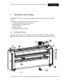
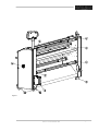
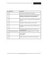
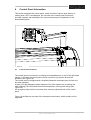
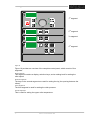
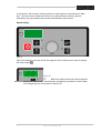
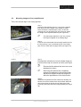
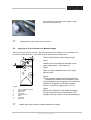
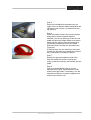
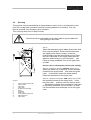
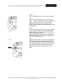
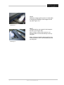
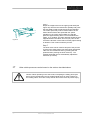
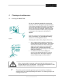
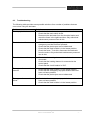
Owner’s manual IMAGE 80S Foreword We would like to thank you for purchasing the IMAGE 80S laminating machine, a laminating machine designed to give you many years of reliable use. The IMAGE 80S is easy to use and will produce a high quality end result. By following the instructions in this manual for correct usage and maintenance you will be able to profit from your investment for many years to come. With the aid of the user’s manual you will quickly learn the necessary actions for the correct use of the IMAGE 80S. Version 2.0 12 December 1999 Owner’s manual IMAGE® 80S Contents INTRODUCTION 1 Installation Information .....................................................................7 1.1 1.2 1.3 1.4 2 Control Panel Overview........................................................................25 Control Panel Functions .......................................................................27 Using the foot pedal .............................................................................36 Set-up and operating of the IMAGE® 80S.........................................39 5.1 5.2 5.3 5.4 5.5 5.6 6 Warnings..............................................................................................18 Safety Features....................................................................................20 Control Panel Information .................................................................25 4.1 4.2 4.3 5 Identification of Parts............................................................................13 Safety and warranty information ......................................................17 3.1 3.2 4 Unpacking the Laminator .....................................................................7 Laminator Identification ........................................................................9 Environmental Conditions ....................................................................10 Working area........................................................................................11 Description of the Laminator ............................................................13 2.1 3 5 Laminator set-up ..................................................................................39 Pre-Coating Boards..............................................................................41 Mounting Images to Pre-coated Boards ...............................................43 Applying an Over-Laminate to a Mounted Image .................................44 Decaling...............................................................................................46 Mounting Laminated Decals.................................................................49 Cleaning and maintenance................................................................51 6.1 6.2 6.3 Cleaning the IMAGE® 80S ...................................................................51 Maintenance of the IMAGE® 80S .........................................................52 Troubleshooting ...................................................................................53 APPENDICES ............................................................................................55 Accessories .................................................................................................... 56 Speed / Pressure / Temperature settings ....................................................... 57 Process Fault Diagrams ................................................................................. 58 Glossary of Laminating Terms........................................................................ 59 Technical specifications.................................................................................. 60 Owner’s manual IMAGE® 80S LIMITED WARRANTY ON IMAGE® LAMINATORS Hunt Graphics warrant to the original consumer purchaser that all new Image laminators that prove defective in materials or workmanship within the applicable warranty period will be repaired or, at our option, replaced without charge. The applicable warranty shall be one year from date of purchase with the exception of silicone roll coverings that will be six months from date of purchase. "Original consumer purchaser" means the person whom first purchased the product covered by this warranty other than for purpose of resale. The warranty extends to and is enforceable by only the original consumer purchaser, and only for the period (during the applicable term) which the product remains in the possession of the original consumer purchaser. For more information regarding this warranty, please contact your distributor. WARNING! Changes or modifications to this unit not expressly approved by the party responsible for compliance could void the user's authority to operate the equipment. WARNING! Any unauthorized changes or modifications to this unit without our prior written approval will void the user's warranty and will transfer health and safety obligations to the user. WARNING! This machine is designed for mounting and laminating. Any use other than the intended may cause damage to the machine or physical harm to the user. Note: This equipment has been tested and found to comply with the limits for a class A digital device, pursuant to part 15 of the FCC rules. These limits are designed to provide reasonable protection against harmful interference when the equipment is operated in a commercial environment. This equipment generates uses and can radiate radio frequency energy and, if not installed and used in accordance with Owner’s Manual, may cause harmful interference to radio communications. Operation of this equipment in a residential area is likely to cause harmful interference in a residential area is likely to cause harmful interference in which case the user will be required to correct the interference at his own expense. 4 Owner’s manual IMAGE® 80S LIABILITY The details given in this manual are based on the most recent information available to us. They may be subject to change in the future. We retain the right to make changes to the construction or the design of our products without accepting any responsibility for modifying laminators previously delivered. We would like to thank you for purchasing the IMAGE 80S laminator, a laminator designed to give you many years of reliable service. The IMAGE 80S is easy to use and will produce a high quality finished product. INTRODUCTION This manual refers to the IMAGE 80S mounting and laminating machine. The manual contains information that is important for the correct operation and maintenance of the laminator. In addition, the manual contains relevant instructions for the prevention of accidents or serious damage, which may occur while operating the laminator. By following the instructions in this manual for correct usage and maintenance you will be able to profit from your investment for many years to come. Using your Owner’ s Manual you will quickly learn the necessary procedures for the correct use of the IMAGE 80S. Owner’s manual IMAGE® 80S 5 Symbols used in this owner’s manual Pay extra attention to the passages marked with this symbol. This information is particularly important for the operation and maintenance of the IMAGE® 80S. + + Passages marked this way offer an idea/tip or offer information on the efficient use of the laminator. Before operating the laminator for the first time, read through the Owner’ s Manual carefully and make yourself thoroughly familiar with the functioning and operation of the laminator. Follow the instructions exactly. If, after reading this manual you still have questions concerning the IMAGE® 80S, or you need more information regarding particular aspects of the laminator, contact your supplier. 6 Owner’s manual IMAGE® 80S 1 Installation information UNPACKING, SET-UP AND INSTALLATION MUST BE PERFORMED BY TRAINED PERSONNEL. The IMAGE® 80S is delivered on a pallet and is packaged in plastic to prevent moisture penetration. A cardboard box is placed over the plastic. For unpacking, location and installation, follow the instructions in the manual. 1.1 Unpacking the Laminator Unpack the laminator in the order of the following steps, which correspond to the numbers in Figure 1. This figure shows how the laminator is mounted on the pallet. 1 Remove the steel bands that are fixed over the box and lift the box off the machine. Remove the protective plastic covering and the loose components (control panel, combi-pack and accessory box). The plastic can be used later as a dust cover. The machine is attached to the pallet with four transport bolts. Open the doors of the cabinets and remove the four bolts with the aid of the 19 mm wrench supplied with the laminator. The bolts are located inside the cabinet. Figure 1 2 Turn down the adjustable feet to raise the laminator off the wooden support blocks using a 10 mm hex key on the bolt head inside the cabinet and a no. 12 open-ended wrench on the red disc. Owner’s manual IMAGE® 80S 7 3 Remove the wooden blocks (3) from beneath the outer edges of the cabinets which the transport bolts pass through. 4 Turn the support blocks under the laminator to allow the laminator to be rolled off the pallet. Screw the adjustable feet upwards, so that the laminator is supported on its moveable castor wheels. Step 5 must be performed by two or more persons. Never do this alone. 5 Roll the laminator off the pallet using the board ramp and push the laminator to the location where it is to be used. 6 Use a spirit level to level the laminator. Place the spirit level on the front table to level the laminator in the longitudinal direction. Next place the spirit level on both side cabinets to level in the transverse direction. A registered installer must do the following steps! 7 Cut through the straps (1) holding the rollers in position (see Figure 2). Figure 2 8 8 Install the control panel arm and the heating element (see paragraphs I and II in the Installation manual). Owner’s manual IMAGE® 80S 9 Check that your power supply voltage is the same as the voltage stated on the type plate (see paragraph III, in the installation manual). Insert the plug in the power supply socket and the machine is ready for use. When the main switch is set to ON, the upper roller will move automatically to the upper position. Finally, the wooden blocks can be removed (2). + Keep the pallet, the box and the transport bolts for any future re-housing of the machine. If it is necessary to move the machine again after it has been installed, remove the glass heating element to avoid breakage. 1.2 Laminator Identification Figure 3 Each Image laminator is fitted with a laminator identification plate at the rear of the right-hand cabinet. This plate indicates the model type, the electrical requirements, and the laminator serial number (important for reference if any servicing is required). Owner’s manual IMAGE® 80S 9 1.3 Environmental Conditions Specific environmental conditions are ideal for the best operation of the laminator. Temperature The best temperature for the IMAGE® 80S is between 10°C and 35°C (50°F and 95°F). Do not expose the laminator to direct sunlight as output quality may be affected. Relative humidity The relative humidity for the IMAGE® 80S may vary between 30% and 95%. The ideal relative humidity is 55%. Too much humidity will affect the prints being laminated causing problems with film adhesion. Water and moisture If the laminator is installed in a damp room or in the vicinity of water, the electrical power supply must be in accordance with the standards prevailing in the country concerned. Surroundings Install the laminator in surroundings that are as clean and dust free as possible in order to obtain the highest quality end product. The materials that are used on this laminator can have an electrostatic charge and will attract dust, adversely affecting the output. Power supply Connect the machine in accordance with the details given on the identification plate attached to the rear of the machine. Refer also to the technical specifications in this section for more information. + The IMAGE â 80S has a power consumption of approximately 7 kW. Because of the heat produced by the laminator, it should not be installed in the same room as, for example, an electrostatic plotter. The IMAGE 80S is provided with a 6 meter (20 feet) long power supply cable with a connector conforming to the specifications stated on the identification plate. In the event that the cable or the connector must be changed, the following recommendations are applicable: Hunt Graphics recommends that a licensed electrician in accordance with electrical codes in your area install your mains power. Specifications subject to change without notice. 10 Owner’s manual IMAGE® 80S 1.4 Working area The machine needs a working area that is at least as wide as the machine plus 60 cm (23.6 in) on both sides. The space required at the front and back of the laminator must be large enough to easily handle the maximum board length (see Figure 4). Figure 4 Owner’s manual IMAGE® 80S 11 12 Owner’s manual IMAGE® 80S 2 Description of the Laminator The IMAGE® 80S is a mounting and laminating machine with a working width of 200cm (78.7 in). The IMAGE® 80S is provided with variable settings for: • the opening between the rollers (the nip) • the temperature of the upper roller • the roller pressure • the roller speed • the supply and take-up tension 2.1 Identification of Parts The parts of the machine are explained in the following to tables. The parts correspond with the numbers shown in the two drawings on the following pages (see Figures 5 and 6). Figure 5 Owner’s manual IMAGE® 80S 13 No. Part name 1 Digital control panel Description Controls for operating the laminator and displays for the temperature, speeds and nip setting. The control panel is mounted on an arm so that the laminator can be operated from any point around the laminator. 2 Feed table The in-feed table used for material input, flips up to allow for easy webbing. The table is designed with an integrated emergency stop system. 3 Removable image guide To achieve a good end result it is necessary that images be passed through the laminator in a flat, even condition. The image guide prevents problems with paper infeed and is removable when mounting boards. 4 Rollers The rollers have a covering of silicone rubber to prevent adhesive build-up, making cleaning quick and easy. 5 Supply position The shafts are suitable for laminate rolls with a 3-inch core. All the shafts are equipped with a rubber blocking cord to secure the rolls of material on the shaft during use (auto-grip system). 6 Auto-grip shaft brake A simple means of setting the tension for the delivery/take-up system. 7 Removable auto-grip shaft Removable auto-grip shafts are shafts on which the laminate is mounted and from which it is unrolled. The shafts can be fitted quickly and easily by means of a clickin system, making it possible to change materials quickly and without problems. All auto-grip shafts on the laminator are the same. 8 Take-up position This position is used for winding up the release liner, finished images or other laminate material. 9 Castors 10 Quick reference guide For easy movement of the laminator. The castors are also equipped with an adjustable foot. A condensed laminator reference guide, giving information on recommended films, temperatures, speeds and webbing. 14 Owner’s manual IMAGE® 80S Figure 6 Owner’s manual IMAGE® 80S 15 No. Part name 11 Tape dispenser Description A holder for adhesive tape beneficial for securing release liners to take-up shafts and other purposes. These are fitted on the front and rear sides of the rollers. If the beam is interrupted, the laminator will stop running immediately. These photo-eyes can be overridden by using the slow-mode function (see paragraph 4.3). 12 Photoelectric cells 13 Foot pedal Allows for complete user control when initially feeding an image into the nip or for feeding a delicate image through the rollers. 14 Emergency stop button Stops the laminator completely when pressed. To re-start the laminator, the button must be turned to reset. 15 Main switch Switch for turning the machine ON and OFF. The door of the cabinet can only be opened when the switch is in the “0” position. 16 Safety cord 17 Feed table supply position This has an emergency stop function. Once the safety cord has been activated, pressing the blue switch can reset the laminator. The supply position for images on a roll. (2” or 3” core) 18 Electrical wind-up Provides the possibility to work from roll to roll. Europe: optional USA: standard 19 Identification plate Detailed machine information and CE identification marking. Contains the serial number for the laminator. 16 Owner’s manual IMAGE® 80S 3 Safety and warranty information ® The IMAGE 80S is designed with safety and protective devices with the user’ s safety of utmost consideration. However, following safe operating guidelines is still the responsibility of the operator. Hunt Graphics Europe B.V. has taken every precaution to provide you with correct information concerning all risks connected with the operation of the laminator. You must ensure that the stated rules of conduct are followed. The purchaser/user is required to make him/herself familiar with these instructions. After delivery, the products supplied must be checked for: • Correctness and completeness: does the delivery include all the articles on the order? • Damage and/or parts missing as a result of transport. Ensure that the transport company representative makes out a damage report before leaving. In the case of damage, always contact the supplier. Work safely! + + Read the safety instructions carefully. Contact the supplier if there is anything that is not clear. Tie up long hair and do not wear jewelry or loose clothing in close proximity of rotating parts. NEVER use a knife to cut material directly on the rollers! Any resultant damage is not covered by the terms of the warranty. Always use an enclosed blade cutter to prevent damage and avoid expensive replacement costs. + + Ensure that the materials fed into the laminator are free from staples, paperclips and other hard or rough materials. Keep the nip entry free from other materials such as pens, tools, etc. The rubber covering on the rollers is soft. Be careful to avoid scratches caused by sharp objects, fingernails, etc. When the laminator is not in use, always ensure that the top roller is in the raised position to prevent flat spots from developing. Flat spots will affect the quality of the output and is not covered by the warranty. Owner’s manual IMAGE® 80S 17 SERVICING AND REPLACEMENT PARTS Service and maintenance must be performed fully in accordance with the instructions. Servicing by any unauthorized technician voids the warranty. The service technician must use replacement parts specified by Hunt Graphics. Call Technical Service for assistance (see rear cover for the location nearest you.) + + Service technicians must perform safety checks after completing any service or repairs to the laminator. Worn parts do not fall under the terms of the warranty. 3.1 WARNINGS The following safety-warning labels are placed on the laminator in relevant locations (see Figures 7 & 8). Hot surface: Risk of injury on contact Take care with hot components. The temperature of the heated roller can be 130°C (266°F). Do not touch the roller. Even after switching off the laminator, the roller remains hot for a long time. Rotating parts: Risk of injury The laminator is equipped with photoelectric eyes, protective covers and doors to prevent contact with rotating parts. Ensure that the safety measures are observed. Be careful that items such as loose clothing, long hair and neckties do not become entangled in rotating parts. Risk of damage to equipment or injury to persons These notices warn you about things that can result in life-threatening situations or damage to the equipment. 18 Owner’s manual IMAGE® 80S Owner’s manual IMAGE® 80S 19 3.2 Safety Features Photoelectric Safety Eyes Because the machine can run continuously at high speed in both directions, photoelectric eyes are mounted on both sides of the roller opening. The laminator stops if one of these eyes is interrupted. For example, if a panel is thicker than the pre-set nip value or if someone puts a hand into the nip opening. The eyes are set for use at the factory and should not be adjusted except by a service representative. (See Figure 9 for location). Figure 9 Emergency Stop Buttons Emergency stop buttons are located on both sides of the laminator and on the control panel (see Figures 10 and 11). To reset the machine after an emergency stop, rotate the red button clockwise. Use these only in the case of an emergency or you may damage an image during a process. Figure 10 Figure 11 Door Locks The side cabinets of the laminator house the electrical components and the motors with the chain wheels. For reasons of safety, these cabinet doors are locked with a key (see Figure 12). The same key is used to unlock both doors. Figure 12 Do not use the side cabinets of the laminator for the storage of materials. This can result in damage to the inner workings or personal injury and will void the warranty. 20 Owner’s manual IMAGE® 80S Safety Cord Switch As an additional safety precaution, a safety cord the length of the laminator is attached to the front (see Figures 13 and 14). The safety cord can be operated with the foot and like the emergency stop buttons; the cord switches off the laminator. Figure 13 Reset the laminator by pressing the blue switch (see Figure 14). Figure 14 Foot Pedal Figure 15 Pressing the foot pedal runs the laminator in the forward direction at the speed indicated on the display. Releasing the pedal stops the roller rotation. Possible combinations with the foot pedal are: • Press the foot pedal and then press the forward key and keep it depressed; release the foot pedal, thereafter release the forward key. Result: without the foot pedal being used to stop the machine (hands free), the laminator switches over to the control panel (continuous). • Press the foot pedal and thereafter press the Slow Mode key. Result: the laminator runs at 0.6m/min (2.0 ft/min.); safety sensors are not operational. • Press the edge mount key and thereafter the foot pedal. Result: the edge mount function is operational (see paragraph 4.3). Owner’s manual IMAGE® 80S 21 During the slow mode, the photoelectric-eyes are not operational. Main Switch The main switch (see Figure 16) is mounted on the right side cabinet door. This switch has two positions; I ON (laminator on); O OFF (laminator off); Figure 16 22 The switch can be secured with a padlock in the OFF position to prevent any unauthorized operation of the laminator. The right side cabinet housing the electrical circuits cannot be opened unless the switch is in the OFF position This switch also has a reset function. Switch the laminator off and disconnect it from the main power before opening the cabinet doors. Owner’s manual IMAGE® 80S Figure 17 The rollers and the auto-grip shafts will stop if: • The stop push button on the control panel is pressed. • One of the emergency stop buttons is pressed. • The safety cord on the front of the laminator is activated (emergency stop circuit). • The feed table is raised (see Figure 48). • The photo-eyes at the front or the rear of the rollers are interrupted (depending on the direction of rotation). • The foot pedal has been depressed and subsequently released. • If the machine is overloaded (for example, too great an unrolling tension). This will cause the thermal cut-out in the motor to operate. Reset the machine by switching the main switch off and on again. When the laminator is not running: • Operating one of the emergency stop push buttons or the safety cord or raising the input table will prevent any further functions being accessible. • If one of the photo-eyes is interrupted while the top roller is moving downward, the setting of the roller will be stopped and the nip value attained will be shown on the display. If the photocells remain interrupted, the downward movement can be continued by means of: * pressing the slow-mode key; * pressing the roller movement down key. Owner’s manual IMAGE® 80S 23 24 Owner’s manual IMAGE® 80S 4 Control Panel Information This section describes the control panel, which consists of various push buttons, a rotating knob, LED’ s and displays. An overview of the control panel functions is provided, together with drawings of the control buttons and an explanation of the associated symbols. Figure 18 4.1 Control Panel Overview The control panel is mounted on a rotating and extendable arm on top of the right-hand cabinet. In this way the control panel can be used from any position around the laminator (see Figure 18). The control panel is designed with a keyboard fitted with membrane keys for fast and accurate operation. A group of 3-digit displays provide readouts of the roller speed, the nip setting (the roller opening), the roller pressure and the temperature, among other things (see Figure 19). An emergency stop button is mounted at the extreme right-hand side of the control panel. Figure 19 provides an overview of the complete control panel, which consists of four segments: Owner’s manual IMAGE® 80S 25 1st segment 2nd segment 3rd segment 4th segment Figure 19 Figure 19 provides an overview of the complete control panel, which consist of four segments: First segment This segment contains a display, selection keys, and a rotating knob for setting the roller speed. Second segment The keys in the second segment are used for setting the nip (the opening between the rollers). Third segment The third segment is used for setting the roller pressure. Fourth segment This is used for setting the upper roller temperature. 26 Owner’s manual IMAGE® 80S 4.2 Control Panel Functions First segment The speed of the rollers is continuously adjustable between 0 and 5m/min. (0 and 16.5 key runs the rollers in the forward, while pressing the key ft/min). Pressing the reverses the direction of the rollers. The stop key stops the roller movemen. The 3-digit display shows the roller speed. Second segment The nip setting is used to set the roller opening, which is continuously variable between 0 and 25.4 mm (1"), and which can be set with the keys. The maximum opening is 30 mm (1 1/8”). While the nip setting is being adjusted, the actual size of the opening is shown in the second display on the control panel. Third segment The roller pressure is continuously variable between 0.75 N/mm en 1.6 N/mm and can keys. The pressure can be read from the third display on be adjusted using the the control panel. Fourth segment The temperature of the upper roller is continuously adjustable between 40°C (100°F) key is pressed, the fourth display on the control panel and 130°C (266°F). When the shows the temperature setting. During use the display will show the actual roller temperature. Owner’s manual IMAGE® 80S 27 In this section, the functions of the symbols for each segment are presented in table form. The first column shows the function key, while the second column gives a description of the key and the third column described the key function. Speed display Figure 20 Figure 20 shows an overview of the first segment of the control panel, used for setting the roller rotation . Figure 20a + When the display shows the stripes depicted above (see Figure 20a), check all three emergency stop buttons, feed-in table and emergency stop cord (see also Section 6). 28 Owner’s manual IMAGE® 80S Button/key/display Description Function Stop key Stops the rotation of the rollers. Display for roller speed, emergency stop, photoeyes or error message. Displays the roller speed in m/min or ft/min. The roller speed can be pre-set. Forward roller direction The rollers rotate in the forward direction. Reverse roller direction The rollers rotate in the reverse direction. When the key is released, the rollers stop rotating. Speed regulator knob The speed of the rollers is continuously variable and can be set to any value from 0 to 5 m/min. (16.5 ft/min.) Slow mode key Using this key changes the laminator over to the ‘ slow mode’ and switches off the photo-eyes. An audible signal is given to warn of close proximity to the rotating rollers. The rollers will now run at a safe speed of 0.6 m/min (2 ft/min) in the forward direction, controlled only by the foot pedal. Press the reverse roller direction key to run the rollers in slow mode in the reverse direction. Edge mount key + For attaching laminate around the edges. After this key has been pressed, the foot pedal can be used for “hands-free” operation. When the display shows a value other than speed, refer to Section 6. Owner’s manual IMAGE® 80S 29 The rollers will stop rotating if: • The photocells are interrupted; • One of the emergency stop buttons is pressed; • The foot pedal is pressed momentarily; • The feed table is raised; • The machine is too heavily loaded, so that the motor thermal cut-out operates. Reset by switching the main switch off and on again. • The stop key on the control panel is pressed; • The safety cord is activated. Reset the switch by pressing the blue knob on the switch. When work is being performed in slow mode operational. 30 Owner’s manual IMAGE® 80S , the photocells are not Nip setting Figure 21 Figure 21 shows the second segment of the control panel. These keys adjust the distance between the rollers (= the nip setting). + Always adjust the nip setting to the thickness of the board! Key/display Description Function Nip opening display (or The display indicates the gap between the error message). rollers. The gap can be adjusted to between 0 and 25.4 mm (1"). If a value between 0 and 0 en 3 mm (.12 in) is set, the rollers remain in contact. Raise the roller This increases the gap between the rollers (maximum 25.4 mm (1")). Keep the key pressed until the display shows the desired value. Pressing the key replaces the previous value. Lower the roller + This decreases the gap between the rollers. The actual value of the setting is less than that indicated in the display creating a press of 0.6 mm (.025 in) on the substrate. The nip setting cannot be changed to a smaller value when there is a panel between the rollers. In this case, the display will show error message Er1. When the display shows a value other than distance, refer to Section 6. Owner’s manual IMAGE® 80S 31 + The up and down movement of the upper roller can be interrupted by entering a new nip setting, interrupting the photo-eyes or by pressing an emergency stop. + Ensure that the upper roller is in the uppermost position before switching off the machine to avoid getting flat spots on the rollers. The nip setting can only be changed if: • No emergency stop has been activated; • The feed table is in the lowest position. If the upper roller performs a downward movement while the nip is being adjusted, this movement will stop if the photo-eyes are interrupted. To overrule this action, press the footswitch when the roller is moving downwards. When the roller movement stops by photo-eyes, the setting reached will be indicated in the display. To avoid tripping the safety eyes by the upper film while lowering the roller: keep the upper film under tension by manually rotating the unwind shaft a bit. Also in slow mode, the photo-eyes are not operational and you can lower the roller using the roller down key . If there is a panel between the rollers, the nip setting CANNOT be set to a lower value. 32 Owner’s manual IMAGE® 80S Roller pressure setting Figure 22 The third segment of the display is used to set the roller pressure. This roller pressure can be set to values between 0.75 N/mm and 1.6 N/mm. The roller pressure is shown in the corresponding 3-digit display on the control panel. This function enables different material widths to be processed with the correct pressure. Key/display Description Function Display of roller pressure or error message. Increase the roller pressure The roller pressure can be set to between 0.75 N/mm and 1.6 N/mm. This pressure is applicable when the material used has the same width as the working width of the laminator. Roller pressure setting for any combination of paper or board size. Decrease the roller pressure Roller pressure setting for any combination of paper or board size. Owner’s manual IMAGE® 80S 33 Roller temperature Figure 23 The fourth segment of the control panel is used for regulating the roller temperature. The temperature of the upper roller can be continuously adjusted to any desired temperature between 40°C (100°F) and 130°C (266°F). The temperature setting is shown in the corresponding 3-digit display on the control panel. The temperature is pressed. setting is only displayed when the key with a thermometer symbol During the laminating process, the display shows the actual roller temperature. 34 Owner’s manual IMAGE® 80S Key/display Description Function Display of temperature setting (or error message) The display shows the actual roller key is pressed, the temperature. When the temperature setting is displayed The LED in Switching on/Setting/display temperature the lower right-hand corner flashes during the heating cycle and remains lit when the set temperature is reached. When the LED flashes rapidly, the temperature of the roller is higher than the set point. Use this key in combination with the ‘heating on’ or ‘heating off’ key to switch the heater on or off. Also use this key to set the required temperature. Keep this key pressed while using one of the two following keys to set the correct value. Pressing this key alone displays the temperature setting. Increase the temperature Use this key is, in combination with the key, to increase the temperature. When the key is pressed for two seconds, the temperature setting will be increased by 10°C. Decrease the temperature Use this key is, in combination with the key, to decrease the temperature. When the key is pressed for two seconds, the temperature setting will be decreased by 10°C. Heating on Use this key is, in combination with the key to switch the heater on. When the heater is on, the LED in the lower right-hand corner of the display will be lit. Heating off Use this key is, in combination with the key to switch the heater off. When the heater is off, the LED in the lower right-hand corner of the display will not be lit. Owner’s manual IMAGE® 80S 35 4.3 Using the foot pedal The function of the foot pedal is to permit the rotation of the rollers to be controlled in a hands-off manner. When the speed has been set on the control panel and the safety photo-eyes are not interrupted, the rotation of the rollers can be started by operating the foot pedal. When the pedal is released, the safety photo-eyes are interrupted or an emergency stop has been activated, the rotation will stop immediately. Figure 24 ® The IMAGE 80S also has a so-called slow-mode. The slow-mode key must be pressed. Pressing this key in combination with the foot pedal, the roller rotates with a fixed speed of 0.6 m/min. (2 ft/min). Caution: The safety photo-eyes are not operational. When the foot pedal is released, the rotation will stop immediately. For edge mounting on boards, use the edge mount key . After the edge mount key has been pressed, the laminate can easily be applied to the board. It is important first to set the nip for the correct board thickness. The speed must also be set beforehand (advisory speed = 1 m/min (3.3 ft/min). When the foot pedal is operated, the panel will move forward. As soon as the foot pedal is released, the roller will be raised by five millimeters. This allows the board to be turned over, so that the process can be repeated on the other side. Pressing the foot pedal momentarily will cause the upper roller to resume the pre-set position. Caution: do not place the board in the nip opening! After this, the procedure previously described will be repeated. During edge mounting there is a possibility that the safety photocells will become interrupted. In this case it is advisable to use the slow-mode key 36 Owner’s manual IMAGE® 80S . Take the following steps to switch over from normal speed to the slow mode without stopping the laminator; (This will prevent stop marks appearing in the material) • • • Operating in slow mode combined with using the foot pedal, Press and hold the roller direction forward key, without releasing the foot pedal; Then release the foot pedal; Next release the direction forward key. + The machine assumes the speed set on the speed regulator! Take the following steps to switch over from normal speed to the slow mode without stopping the machine: • The machine is running at the pre-set speed. • Press the foot pedal. • Then press the slow mode key 0.6m/min (2.0ft/min) + . The forward speed automatically slows to As soon as the foot pedal is released, the machine will stop When the machine is running in the slow mode, the photo-eyes are not operational An audible signal warning of close proximity to rotating rollers will be sounded. The speed will be 0.6 m/min (2.0ft/min). Owner’s manual IMAGE® 80S 37 38 Owner’s manual IMAGE® 80S 5 Set-up and operating of the IMAGE® 80S This section contains instructions for the set-up and operation of the IMAGE 80S. This includes processes for pre-coating boards, creating a decal (sticker), board mounting, etc. You can perform the above mentioned processes in different ways as outlined in the next paragraphs. The 3-step process In the 3-step process, a board is first coated with a pressure sensitive mounting adhesive. Next, an image is applied to the adhesive coated board. Finally, a transparent protective laminate is applied to the image front. Paragraphs 5.2 to 5.4 explain these three steps. The 2-step process In the 2-step process, a layer of protective laminate is applied to the front of the image while a self-adhesive layer is applied to the back. Next, the image is applied to a board. Paragraphs 5.5 and 5.6 explain these two steps. 5.1 Laminator set-up These are actions that form part of the 3-step process. The following steps outline the basic procedures that will be used for loading materials, webbing the laminator and setting the brake tension for the materials you will be using. Step 1 Figure 25 Remove the desired supply shaft (top or bottom) by sliding it to the left against the spring pressure (see Figure 25). Lift the shaft out of the laminator. + The auto-grip shaft is heavier on the braking side. +NOTE: The brake is always on the side of the control panel. Step 2 Figure 26 Slide the shaft into a roll of self-adhesive laminate (see Figure 26). Ensure that the rubber blocking cords are on the top and bottom of the shaft for easy loading. Owner’s manual IMAGE® 80S 39 + Take care that the ends of the shaft do not become damaged during the loading and unloading of the laminator. Step 3 Place the shaft holding the roll of laminate back into the laminator by inserting it in the supply shaft holders and rotate it until it clicks. Always place the brake for the auto-grip shaft on the control panel side. Center the roll of laminate in the laminator using the tape measure on the auto-grip shaft. Always work in the centre of the machine! Figure 27 + Ensure that the adhesive side is facing out (see Figure 27). Step 4 Unroll the laminate off the top supply shaft so that an adequate length lies on the in-feed table (see Figure 28). If necessary, release the auto-grip shaft brake. Figure 28 Step 5 Tighten the supply brake (Figure 29) so that it applies sufficient tension to the laminate. Turning the knurled collar in a clockwise direction increases the braking tension applied on the laminate. Turning the collar counter-clockwise decreases the tension. The best setting for the brake tension is determined by the materials you are using and is learned through experience. Step 6 If using a laminate on the bottom, repeat the above procedures for the bottom supply shaft. Figure 29 Step 7 Set the temperature of the upper roller (if required) to the correct setting. Refer to the temperature table in the appendices. Step 8 Refer to the following sections for specific webbing diagrams based on the process you are performing. Do not over tighten the brake. The weight of the auto-grip shaft with a full roll is considerable. Always lift this weight with two persons. 40 Owner’s manual IMAGE® 80S 5.2 Pre-Coating Boards This is the first step of the 3-Step Process. This process is used to coat substrates with a pressure-sensitive mounting adhesive onto which images can be mounted. This same process is used to create a carrier board or sled (see glossary of laminating terms). Figure 30 Step 1 Mount the roll of pressure-sensitive adhesive on the top supply shaft with the exposed adhesive facing out. Step 2 Measure the thickness of the board to be coated and adjust the nip setting to correspond to the thickness of the board. The nip setting is shown on the second display. + Figure 31 Always adjust the nip with no board between the rollers! Step 3 To prevent creases and air bubbles forming during the application of the laminate, always use a leader board. For this, use a short section of scrap board material the same thickness as the board to be coated (see Figure 30). Step 4 Figure 32 Figure 33 Insert the leader board, together with the laminate, into the nip opening. Using the foot pedal, push the front edge of the leader board into the nip. Before the rear edge of the leader board exits the roller, butt the board to be laminated up against the leader board (see Figure 31) and allow the board to run through the laminator (Figures 32 and 33). If necessary, use the foot pedal (refer to the instructions for using the foot pedal in section 4.3). If applying an adhesive coating to several boards, send them through continuously without any gaps between them. Follow the last board with a leader board to prevent the laminate getting onto the rollers. Owner’s manual IMAGE® 80S 41 Figure 34 Step 5 After the last image and the ending leader board pass through the rollers, carefully cut off the laminate between the supply shaft and top roller using an enclosed blade cutter (see Figures 34 and 35). Figure 35 Never cut the foil with an ordinary knife or a Stanley knife. Incorrect use of a knife can result in damage to the rubber coating on the rollers, which will void the warranty. After removing the release liner from the pressure-sensitive mounting adhesive, the board has an adhesive coating ready to mount an image to. You can use the Image 80S to mount an image to the board (see section 5.3). 42 Owner’s manual IMAGE® 80S 5.3 Mounting Images to Pre-coated Boards This is the second step in the 3-step process. Step 1 Fold back approximately 25 mm (1 inch) of the release liner along one of the edges of the adhesive coated board. Crease the release paper evenly on this fold, pressing with your fingertips from the center out. Apply the image to the exposed adhesive (see Figure 36). + Figure 36 The final quality depends on the way in which the image is applied on the leading edge. Step 2 Insert the end of the board with the image adhered to into the nip opening. Lay the untacked portion of the image back over the roller and the supply shaft (see Figure 37). Figure 37 Step 3 Peel back the release liner from the board slowly as it is fed into the nip one section at a time (see Figure 38). + + Figure 38 Ensure that the release liner does not come between the rollers! Removing the release liner completely exposes the adhesive to dirt and dust that will become trapped under the image and affect the appearance of the final product. Step 4 Using the foot pedal leaves the hands free, allowing one hand to remove the release liner off the board. While the other hand keeps the image smooth against the roller preventing the image from becoming wrinkled (see Figure 39). Figure 39 Owner’s manual IMAGE® 80S 43 The board with the final edge of the image is being processed (see Figure 40). Figure 40 + 5.4 Always work in the centre of the machine! Applying an Over-Laminate to a Mounted Image After mounting the image to a board, a protective laminate can be applied. The over-laminate can be a heat-activated laminate or a pressure-sensitive adhesive with a release liner. This is the third step of the 3-Step Process. Step 1 Load the roll of self-adhesive laminate on the upper supply shaft À(see Figure 41). Step 2 Place an empty cardboard core on the upper take-up shaft ‚. Step 3 Pull the laminate forward under the guide roller Ç. Separate the release liner and attach it to the empty cardboard core using tape. Ensure that the laminate is subjected to a minimum braking tension. If necessary, apply heat (< 50 ºC). Figure 41 1. 2. 3. 4. 5. 6. 7. 8. + 44 Upper material supply shaft Take-up shaft Upper roller Lower roller Self-adhesive foil Panel Feed table Guide roller Step 4 Measure the thickness of the board and adjust the nip opening for the correct thickness. The setting for the nip is shown on the second display. Always adjust the nip with no panel between the rollers! Owner’s manual IMAGE® 80S Step 5 Drape the self-adhesive laminate over the upper roller, so that the leader board takes the laminate in with it when it is inserted into the nip opening. Figure 42 Figure 43 Step 6 Place the leader board in the correct position and push the board, together with the laminate, into the nip opening. Press the foot pedal and allow the leader board to be drawn slowly into the rollers. Place the board to be processed immediately behind the leader board and feed it through the laminator (see Figure 42). If desired, take over the feeding of the board through the laminator by pressing the forward key. If necessary, increase the speed. Step 7 Reduce the speed towards the end of the board and after the board is through the rollers, press the stop key and release the foot pedal. Step 8 Use an enclosed blade cutter to cut the laminate (see Figure 43) between the roller and the auto-grip shaft. If necessary, turn the laminate and secure it using the edge-mount method (see section 4.3). Owner’s manual IMAGE® 80S 45 5.5 Decaling This process involves sandwiching an image between either a hot or cold laminate on the front of the image and a pressure-sensitive mounting adhesive on the back. They can later be mounted onto a board or other substrate. This is the first step of the 2-Step Process. Check that both the laminates are the same width to prevent adhesive from getting on the rollers.. Set-up 11 Select the laminates (equal widths) that will be used for the top and bottom. Ensure that the laminates are slightly wider than the image, so that the finished output can later be trimmed to size. Place the rolls of laminate on the supply shafts with the adhesive sides facing out, (see Figure 44) À and È. Place an empty cardboard core on the upper takeup shaft. Set the roller in the highest position (nip setting) Step 1a (Protective laminate without release liner). Switch the heater on (if required). Pull the laminate forward off the supply shaft À and under the guide rollerÇ. If necessary, reduce the brake tension. Drape the laminate over the upper roller. Step 1b: (Protective laminate with release liner). Figure 44 1. 2. 3. 4. 5. 6. 7. 8. 9. 10. 11. 46 Upper materiaal supply shaft Take-up shaft Upper roller Lower roller Protective foil (laminate) Poster Feed table Guide roller Lower material supply shaft Self-adhesive foil Paper guide Pull the laminate forward off the supply shaftÀ, under the guide roller Ç and then up to the take-up shaft Á. Separate the release liner and adhere it with tape to the empty cardboard core on the take- up shaft. Pull the laminate down and drape it over the upper roller  Owner’s manual IMAGE® 80S Step 2 Flip the feed table up to allow for easier webbing. Step 3 Pull the laminate upward from the lower supply shaft È (reduce the brake tension if necessary) and place it over the lower roller Ã. Stick the selfadhesive laminate to the protective laminate draped over the upper roller (see Figure 45). Lower the feed table. Figure 45 Step 4 Press the laminates into the nip opening using the leader board (see Figure 46). If desired, operate the foot pedal just long enough to feed the leader board onto the output table. Caution: the leader board must be completely out of the rollers. Lower the upper roller onto the lower roller (Nip setting =0) Step 5 Figure 46 Adjust the brake tensions of the auto-grip shafts to reduce any wrinkles in the laminate to a minimum. If necessary, roll up the laminate rolls to achieve this. If wrinkles persist, cut the laminate off and roll the laminate off further until there are no more wrinkles and feed the laminate into the rollers again. Owner’s manual IMAGE® 80S 47 Step 6 Attach the image guide onto the in-feed table to simplify the feeding of the image into the nip (see Figure 47). Afbeelding 47 Step 7 The laminator is now ready for the image to be fed in (see Figure 48). Note. If using an electric take-up device, the finished product can be automatically wound up using this. Note. If using an electric take-up device, the finished product can be automatically wound up using this. Afbeelding 48 48 Owner’s manual IMAGE® 80S 5.6 Mounting Laminated Decals This process uses a previously processed image with an adhesive coating on the back and a protective over-laminate on the front. This is the second step of the 2-Step Process. Step 1 Place the board to which the image will be mounted on a flat surface. Lay the image that is to be mounted face down on the board and fold back approximately 25 mm (1”) of the protective paper backing over the full width. Crease along this fold pressing with your fingertips from the center out. Step 2 Turn the image over and adhere the exposed adhesive edge to the board. Step 3 Once the image is properly aligned, press it firmly into position on the board. Smoothing from the center towards the edges will help to ensure that the image is applied flat and without air bubbles. Step 4 Ensure that the nip opening corresponds with the thickness of the board. Step 5 Insert the side of the board to which the image has been attached into the nip opening. Operate the foot pedal until the board is just gripped by the rollers. Owner’s manual IMAGE® 80S 49 Step 6 Figure 49 Drape the image back over the upper guide shaft (see Figure 49). Remove the release liner partially and press the foot pedal to feed the panel through the laminator. The control panel may now be used to take over the feed if desired. Select the speed with the speed regulator on the control panel. Make sure that the protective paper backing does not come between the rollers. If, by accident, the paper backing should become trapped between the rollers, do not try to pull it out but reverse the direction of the rollers until the paper backing is released. Then continue with the process. Step 7 The slow mode can be used for this part of the process to prevent the safety photo-eyes from being interrupted. Take over the forward function by pressing the foot pedal and then pressing the slow mode key . The forward speed will now be automatically adjusted to 0.6m/min (2.0 ft/min). + Other similar processes can be based on the actions described above. Caution: When operating in the slow mode, interrupting the safety photo-eyes does not stop the laminator and an audible signal warns of close proximity to the rotating rollers. Use care to keep hands clear of the rollers to prevent injury. 50 Owner’s manual IMAGE® 80S 6 Cleaning and maintenance 6.1 Cleaning the IMAGE® 80S Do not use abrasive materials for cleaning the laminator. This can damage the painted surfaces or the rubber covering of the rollers. For cleaning, only use a damp cloth. Ensure that water does not run into any of the cabinets. Water may enter the electrical circuits and cause injury to persons or damage to the equipment when power is applied. Figure 50 Clean the outside of the laminator with a damp cloth. If necessary, use a household-cleaning solution for removing difficult marks. Cleaning the rubber rollers (Figures 50 and 51) • • Use a rubber-cleaning block to remove the excess adhesive from the rollers. This is best done with the rollers hot. When cleaning the upper roller, place a piece of waste board under the roller to prevent the removed adhesive remnants from falling onto the lower roller (see Figure 51). For adhesive residue that is difficult to remove, use isopropyl alcohol (IPA) and a clean lint-free cloth. Never pour isopropyl alcohol (IPA) directly onto the machine. Figure 51 When using alcohol for cleaning, make sure that the rollers are cold. Isopropyl alcohol (IPA) is flammable. The self-ignition temperature of IPA is 400°C (752°F). IPA evaporates at 11°C (51.8°F). + The rollers must be cleaned regularly to prevent a build-up of adhesive residue, which may eventually damage the rollers. For cleaning, always use a damp lint-free cloth. Owner’s manual IMAGE® 80S 51 6.2 Maintenance of the IMAGE® 80S The IMAGE® 80S requires little maintenance and only the following is required: • • • • Lubricate both of the roller raising worm wheels in the left-hand cabinet with a molykote (thick grease) twice per year. Wipe the feed table with a dry cloth as needed. Clean the rubber blocking cords on the supply shaft as required. If the blocking cords hang loosely they must be tensioned by first undoing a clamp at one end. Cut approximately 1 cm (0.5 inches) off the end of the cord and secure it again with the clamp. For technical support, consult the supplier. 52 Owner’s manual IMAGE® 80S 6.3 Troubleshooting The following table provides some possible solutions for a number of problems that can occur when using the laminator. Problem The display is blank. Solution • Check that the laminator is connected to the mains; • Check that the main switch is ON. • Disconnect the laminator from the electrical mains and check the fuses in the right-hand box. Only authorized maintenance personnel can do this. The laminator will not run • • • • The roller does not heat up • • • The upper roller cannot be lowered • • • The upper roller cannot be raised • • Check that the emergency stop push buttons or the emergency cord has not been pressed; Check that the photo-eyes are not obstructed; Check that the feed-in table is in the lowest position; Check the fuses. To do this, disconnect the laminator from the mains. Only authorized maintenance personnel can do this. Check that the heating element is installed and connected. Check that the heating element is connected at the control panel. Check that the circuit breaker is “ON”. Check that the feed-in table is in the lowest position; Check that the emergency stop push buttons and cord have not been pressed; Check that the photo-eyes are not obstructed. Check that the emergency stop push buttons and cord have not been pressed; Check that the feed-in table is in the lowest position. Owner’s manual IMAGE® 80S 53 Error messages in the display + 54 Cause Solution Emergency push button on boxes of control panel pressed. Emergency stop cord operated. Feed-in table not in the lowest position. Reset the emergency stop Photo-eyes at the rear obstructed. Remove the obstruction. Photo-eyes at the front obstructed. Remove the obstruction. Drive motor overload. Switch the laminator off at the main switch. Gripper motor overload Switch the laminator off at the main switch. Upper roller cannot be lowered Switch the laminator off at the main switch. Remove the panel Re-adjust the nip. Overload motor pressure setting. Switch the laminator off / on with the aid of the main switch. Laminator does heat up. Switch the laminator off / on with using the main switch. Reset the emergency stop cord by pressing the blue push button on the front of the laminator. Move the feed-in table downward. If any other error messages appear, contact your supplier. Owner’s manual IMAGE® 80S APPENDICES • • • Technical specification IMAGE 80S Accessories Temperature / Speed table Owner’s manual IMAGE® 80S 55 Accessories The following items are supplied with the machine: • • • • • • • • • • • • • • 56 Owner’s manual Quick reference guide Enclosed blade cutter Rubber cleaning block for the rollers Spare fuses (in a bag inside the machine) Set of open-ended wrenches Extra open-ended wrench 6-7 Hexagon key 5 mm Empty film cores (2x) Leader board Tape holder Auto-grip shaft (4x) Dispensing unit for prints / plots on a roll (2 inches of 3 inches) Cutting gauge for edge mount Owner’s manual IMAGE® 80S Speed / Pressure / Temperature settings For the materials listed below, the following variables can be set: SEAL material Print Shield standard / Pro Range Print Mount Range Speed 2 m/min. 6.5 ft/min Pressure 0.9 - 1.0 Temperature Environment to 50 ºC (122 ºF) Brake tension Light 2 m/min. 6.5 ft/min 0.9 - 1.0 Environment to 50 ºC (122 ºF) Light to medium Jet Guard Range 1.5 m/min 5 ft/min. 0.9 - 1.0 90 ºC – 100 ºC (194 ºF – 212 ºF) Light to medium Print Guard Range 1.5 m/min. 5 ft/min. 0.9 - 1.0 85 ºC – 100 ºC (185 ºF – 212 ºF) Light Note : This is advisory. For various materials, a different setting may be necessary. Naturally, this depends on the way the process is carried out. Pre-coating a board Applying an overlaminate Laminating and Decalling 1 Owner’s manual IMAGE® 80S 57 Process Fault Diagrams Figure 52 When the picture displays this pattern, the pressure is too high. Figure 53 When the picture displays this pattern, the pressure is too low. The ideal pressure line is 1N/mm when the full width of the material is used. If there are problems with the use of materials, contact your supplier. 58 Owner’s manual IMAGE® 80S GLOSSARY OF LAMINATING TERMS DECAL An image that has been laminated on top (either heat-activated or pressure-sensitive) with an adhesive backing. HEAT-ACTIVATED LAMINATES Laminates with a dry adhesive that is activated when heat is applied. Once applied to an image the adhesive forms a strong bond locking the laminate and the image together. IN-FEED The side of the laminator from which images are fed. LEADER BOARD A piece of foam board (about 4’ x 2 inches) used to push films into the nip. Also used for mounting or pre-coating boards to prevent adhesive from getting onto the rollers and sealing edges. MIL Refers to the thickness of the laminate. MOUNTING Applying an image onto some kind of foam board or substrate. NIP The spot where the top and bottom rollers meet. OUT-FEED The side of the laminator from which completed images emerge. PRE-COATING The process of coating a substrate with an adhesive mounting film onto which and image can be mounted. PRESS The amount of force in distance put on anything that passes between the top and bottom rollers. Normally a press of .025 is sufficient. PRESSURE-SENSITIVE LAMINATES Laminates with a wet adhesive, which forms a bond between the protective laminate and the surface of the image being laminated. Used primarily for fast mounting applications and recommended for heat-sensitive thermal and photographic prints. RELEASE LINER The backing on a pressure-sensitive laminate or mounting adhesive. After peeling the release liner off, the adhesive layer becomes exposed. SLED (CARRIER BOARD) A piece of smooth, non-crushable board (preferably Masonite) coated with a mounting adhesive and leaving the release liner on to provide the necessary non-stick surface. A piece of foam board can also be used, but it will not have the longevity of the Masonite board. Sleds are used when laminating one side of an image only. SUBSTRATE The material to which an image is mounted or affixed. Owner’s manual IMAGE® 80S 59 Technical specification for the IMAGE® 80S Connection for single-phase power supply 200-250V ±10% 50/60 Hz 25 A Connection for three-phase power supply 3N/PE 200-250V ±10% 50/60 HZ 25 A Data display 4 x 3-digit 7-segment displays Material supply capacity (average roll) Material take-up capacity shafts (average roll) Internal diameter of the tube 1 foot (30 cm) Supply and take-up shaft tension. Set manually on the auto-grip shaft Dimensions (width, depth and height) Machine 270 cm, 81 cm en 166 cm (106.3 inches x 31.9 inches x 65.4 inches) Dimensions (width, depth and height) Packaging Net weight / Gross weight 285 cm, 90 cm, 150 cm (112.2 inches x 35.4 inches x 59 inches) 602 kg / 660 kg Maximum power 6250 Watt Maximum laminating speed 0-5 m/min. (16.4’/min) Maximum roller temperature 130 ºC (266 ºF) Maximum board thickness 25 mm (1 inch) Maximum heated width 2040 mm (80.3 inch) Roller construction Steel roller covered with silicone rubber Roller pressure 0.75-1.6 N/mm Roller opening (Nip) 0-30 mm ( 1 1/8 inches) 60 7 inches (18 cm) 76.2 mm (3 inch) Owner’s manual IMAGE® 80S