Transcript
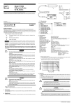
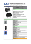
C
User's
Manual
Model 701981
250MHz Logic Probe
for DL Series
250 MHz LOGIC PROBE
B
GND
0
1
2
3 10kΩ/9pF
4
40Vpk
5
6
7
GND
USE
RECOMMENDED
CABLE
ONLY
≤
YOKOGAWA
D
E
A
C
Thank you for purchasing the YOKOGAWA 701981 250 MHz Logic Probe.
To optimize all the functions of the instrument, please read the manual thoroughly before operating it.
0 1 2 3 4
5 6 7 8 9
G
H
F
A
Disk No. DL06
1st Edition : February 2003 (YK)
All Rights Reserved, Copyright © 2003, Yokogawa Electric Corporation
IM 701981-01E
1st Edition
Standard Assessories
Name
B Probe tip
C Earth lead (for main unit)
D Earth lead (for terminal)
E
Cable
F
Pincher tip (black)
G Pincher tip (red)
H Pincher number stickers
Qty
Part No.
8
2
8
1
10
8
1
B9852VM
B9852VU
B9852VV
B9852VN
B9852VX
Optional Assessories
Part No.
Name
B9852ES
IC clip
B9852VY
3. Specifications
Safety Precautions
Make sure to comply with the safety precautions mentioned hereafter when handling the probe.
YOKOGAWA ELECTRIC Co. assumes no responsibility for any consequences resulting from failure to
comply with these safety precautions.
Also, read the User's Manual of the measuring instrument thoroughly so that you are fully aware of its
specifications and handling, before starting to use the probe.
The following symbols are used on this instrument.
To avoid injury, death of personnel or damage to the instrument, the operator must
refer to an explanation in the User's Manual or Service Manual.
Make sure to comply with the following safety precautions in order to prevent accidents such
as an electric shock which impose serious health risks to the user and damage to the
instrument.
Inputs
Nondestructive input voltage range
Threshold level
Threshold level accuracy*1
Input voltage range
Input impedance (typical value)
Minimum input voltage*1
Maximum toggle frequency*1
Minimum pulse width
Hysteresis voltage (typical value)
External dimensions
8
±40 V (DC+AC peak) or 28 Vrms*2
±10 V at 0.1 V resolution
± (100 mV + 3% of setting)
±10 V
10 kΩ//9 pF
500 mVp-p
250 MHz or more
2 ns
50 mV
85.7 mm × 64.2 mm × 20 mm(excluding cable and accessory)
*1 Reference operation conditions:
Ambient temperature 23 ± 2°C; Ambient humidity 55 ± 10%; 30 minutes after the power supply is applied.
*2 For the relation between frequency and input voltage derating see the graph below.
WARNING
• Grounding of the measuring instrument
The protective grounding terminal of the measuring instrument must be connected
to ground.
• Connecting the object of measurement
Make sure to avoid an electric shock when connecting the probe to the object of
measurement. Do not remove the probe from the measuring instrument after the
object of measurement is connected.
• Do not operated with suspected failures
If you suspect that there is damage to this probe, have it inspect by a service
personnel.
• Nondestructive input voltage range
Do not apply any voltages exceeding ±40 V(DC+AC peak) between input and
earth.
• Must be grounded
Before connecting the input terminal of the probe to the object of measurement
ensure that the measuring instrument is properly grounded and that the probe's
output connector is attached to the input connector of the DL.
• Do not operate without cover
To avoid electric shock or fire hazard, do not operate this probe with the cover
removed.
• Do not operate in wet/damp conditions
To avoid electric shock, do not operate this probe in wet or damp conditions.
• Do not operate in explosive atmosphere
To avoid injury or fire hazard, do not operate this probe in an explosive
atmosphere.
• Avoid exposed circuitry
To avoid injury, remove jewelry such as rings, watches, and other metallic objects.
Do not touch exposed connections and components when power is present.
Derating by Frequency
100
Nondestructive input
voltage (V p-p)
WARNING
Logic Probe
40
10
1
1
10
100
1000
Frequency (MHz)
4. How to Use the Probe
1.
2.
3.
4.
Turn OFF the DL’s power switch.
Connect the cable to the logic probe.
Connect the probe tips and earth leads to the logic probe.
Connect the logic probe cable to the probe connector on the DL, then turn ON the DL’s power
switch.
5. Use earth lead B9852VU or B9852VV to connect the ground of the circuit under test. To observe
high speed signals, connect from the probe tip ground using earth lead B9852VV.
6. Connect the probe input to the circuit under test.
Connecting the Probe Tip
Connect the earth leads (for main unit) in the same manner.
CAUTION
• Nondestructive input voltage range
Do not apply any voltages exceeding the Nondestructive input voltage range to the
probe.
• Connecting the Probe to the Circuit under Test
Always use the accessory probe tip when connecting to the circuit under test.
• Connecting the Probe to the DL
Always turn OFF the DL’s power switch when connecting or disconnecting the
logic probe.
• Grounding
The logic probe’s ground connects internally with the DL’s ground.
• Clean the Instrument Properly
Use a soft cloth to clean the dirt. Prevent damage to the probe.
Avoid immersing the probe. Avoid using abrasive cleaners. Avoid using chemicals
contains benzene or similar solvents.
Probe tip
Removing the Probe Tip
Remove the earth leads (for main unit) in the same manner.
Insert a pointed tool such as a pair of tweezers
into the location shown in the figure below,
then drag the tool in the direction of the arrow
to release the probe tip.
The following symbols are used in this manual.
Affixed to the instrument. Indicates danger to personnel or instrument and the operator must refer to the User’s Manual. The symbol is used in the User’s Manual to
indicate the reference.
WARNING
Describes precautions that should be observed to prevent serious injury or death to
the user.
CAUTION
Describes precautions that should be observed to prevent minor or moderate injury,
or damage to the instrument.
Note
Provides important information for the proper operation of the instrument.
Note
Accurate measurement may not be possible near objects with strong electric fields (like
cordless equipment) or strong magnetic fields (like transistors or large current circuits).
1. Description
The model 701981 250 MHz Logic Probe has a maximum toggle frequency of 250 MHz and accepts
up to 8 bits of input.
2. Appearance
As shown in the following illustration, the probe consists of a main body and standard accessories.
IM 701981-01E 1st Edition