1
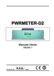
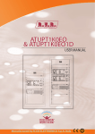
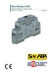
PJ3500M-C & PJ5000U-K USER MANUAL VOLUME1 Manufactured by R.V.R ELETTRONICA S.p.A. Italy File Name: PJ3500M-C_5000U-K_ING_1.0.indb Version: 1.0 Date: 05/04/2013 Revision History Date Version 05/04/2013 1.0 Reason First Version Editor J. H. Berti PJ3500M-C & PJ5000U-K - User Manual Version 1.0 © Copyright 2013 R.V.R. Elettronica SpA Via del Fonditore 2/2c - 40138 - Bologna (Italia) Telephone: +39 051 6010506 Fax: +39 051 6011104 Email: [email protected] Web: www.rvr.it All rights reserved Printed and bound in Italy. No part of this manual may be reproduced, memorized or transmitted in any form or by any means, electronic or mechanic, including photocopying, recording or by any information storage and retrieval system, without written permission of the copyright owner. Declaration of Conformity Hereby, R.V.R. Elettronica SpA, declares that this FM transmitter is in compliance with the essential requirements and other relevant provisions of Directive 1999/5/EC. PJ3500M-C & PJ5000U-K WARNING The following information is needed in order to perform the change of output power. The non-respect of this content may cause damage to the equipment or to the people. Menus and images are for illustration purposes only and may differ from reality. 1. Startup procedure for TX with PJ3500U-K GREEN LINE amplifiers 1 2 3 4 5 6 7 8 9 10 Turn ON the exciter using the front switch Set the output power of the exciter to zero. Set the exciter frequency to the working value Turn on the amplifier. On amplifier rotate trimmer RF PWR ADJ completely counterclockwise to set the power to 0. Adjust the exciter output to have 50W at amplifier input. To check it press “ESC” key then select “Pwr” menu then press down arrow to visualize the measure. Note: The input power value read from the amplifier may differ from the one read from the modulator. Press “ESC” key until the display shows the main screen (FWD and RFL readings) Adjust output power using RF PWR ADJ trimmer. After ten minutes, readjust the output power of the amplifier(s), it will be lowered due to heating. Repeat the procedure if the carrier frequency is changed. User Manual Rev. 1.0 - 05/04/13 PJ3500M-C & PJ5000U-K WARNING The following information is needed in order to perform the change of output power. The non-respect of this content may cause damage to the equipment or to the people. Menus and images are for illustration purposes only and may differ from reality. 1. Startup procedure TX with PJ5000U-K GREEN LINE amplifiers 1 2 3 4 5 6 7 8 9 10 ii Turn ON the exciter using the front switch Set the output power of the exciter to zero. Set the exciter frequency to the working value Turn on the amplifier. On amplifier rotate trimmer RF PWR ADJ completely counterclockwise to set the power to 0. Adjust the exciter output to have 50W at amplifier input. To check it press “ESC” key then select “Pwr” menu then press down arrow to visualize the measure. Note: The input power value read from the amplifier may differ from the one read from the modulator. Press “ESC” key until the display shows the main screen (FWD and RFL readings) Adjust output power using RF PWR ADJ trimmer. After ten minutes, readjust the output power of the amplifier(s), it will be lowered due to heating. Repeat the procedure if the carrier frequency is changed. Rev. 1.0 - 05/04/13 User Manual PJ3500M-C & PJ5000U-K DECLARATION OF CONFORMITY We, the undersigned, Manufacturer’s Name: R.V.R. Elettronica SpA Manufacturer’s Address: Via del Fonditore 2/2c Zona Ind. Roveri 40138 Bologna Italy Certify and declare under our sole responsibility that the product: Product Description: FM Amplifier for VHF audio broadcasting Model: PJ3500M-C Frequency Range: 87.5 - 108.0 MHz RF Power Output: 350 - 3500 W when used for its intended purpose, is in compliance with the essential requirements and other relevant provisions of Directive /5/CE “R&TTE”, and therefore carries the “CE” mark. The conformity assessment procedure referred in Article 10 and detailed in Annex III of Directive 99/5/EC has been followed. The following harmonized standard have been applied: EMC (3.1b): EN 301 489-1 V1.4.1 (2002-08) + EN 301 489-11 V1.2.1 (2002-11) Safety (3.1a): EN 60215:1989 + EN60215/A1:1992-07 + EN60215/A2:1994-09 The technical documentation is held at the location above, as required by the conformity assessment procedure. Bologna, Italy, 29/05/2009 Ravagnani Stefano Technical Manager R.V.R. Elettronica S.p.A. Rev. 1.0 - 29/05/2009 User Manual Rev. 1.0 - 05/04/13 iii PJ3500M-C & PJ5000U-K DECLARATION OF CONFORMITY We, the undersigned, Manufacturer’s Name: R.V.R. Elettronica SpA Manufacturer’s Address: Via del Fonditore 2/2c Zona Ind. Roveri 40138 Bologna Italy Certify and declare under our sole responsibility that the product: Product Description: FM Amplifier for VHF audio broadcasting Model: PJ5000U-K Frequency Range: 87.5 - 108.0 MHz RF Power Output: 500 - 5000 W when used for its intended purpose, is in compliance with the essential requirements and other relevant provisions of Directive /5/CE “R&TTE”, and therefore carries the “CE” mark. The conformity assessment procedure referred in Article 10 and detailed in Annex III of Directive 99/5/EC has been followed. The following harmonized standard have been applied: EMC (3.1b): EN 301 489-1 V1.4.1 (2002-08) + EN 301 489-11 V1.2.1 (2002-11) Safety (3.1a): EN 60215:1989 + EN60215/A1:1992-07 + EN60215/A2:1994-09 The technical documentation is held at the location above, as required by the conformity assessment procedure. Bologna, Italy, 29/05/2009 Ravagnani Stefano Technical Manager R.V.R. Elettronica S.p.A. Rev. 1.0 - 29/05/2009 iv Rev. 1.0 - 05/04/13 User Manual PJ3500M-C & PJ5000U-K Technical Specification PJ3500M-C PJ5000U-K GENERALS 87.5 ÷ 108 3500 <75 (80 typical) 0 to + 50 (operational -10) 87.5 ÷ 108 5000 <75 (80 typical) 0 to + 50 (operational -10) monophase/biphase 230 +10% -15%(*) 400 +10% -15% (**) 5157 5147 Typical 68 0,998 ILME CFX 4/2 monophase/biphase 230 +10% -15%(*) 400 +10% -15% (**) 7366 7352 Typical 68 0,998 ILME CFX 4/2 mm mm mm mm kg 483 2 x 132 695 650 about 55 483 2 x 132 695 650 about 55 dBA Forced with internal fans 78 Forced with internal fans 78 Ohm W W N type 50 70 (typical 50) 100 N type 50 70 (typical 50) 150 7/8" EIA 50 BNC 50 approx. -60 7/8" EIA 50 BNC 50 approx. -60 BNC DB15M DB9F DB25F VDE F BNC DB15M DB9F DB25F VDE F On Mains 3 External fuses F16T 10x38 (Threephases 400V) 3 External fuses F20T 10x38 (Threephases 230V) 3 External fuses F25T 10x38 (Monophase 230V) 3 External fuses F16T 10x38 (Threephases 400V) 3 External fuses F20T 10x38 (Threephases 230V) 3 External fuses F25T 10x38 (Monophase 230V) Parameters U.M. Conditions Frequency range Rated output power Spurious & harmonic suppression Ambient working temperature MHz W dBc °C POWER REQUIREMENTS Power supply type AC Power Input DC Power Input AC Supply Voltage VAC AC Apparent Power Consumption Active Power Consumption VA W % Overall efficiency Power Factor Connector DC Supply Voltage DC Current MECHANICAL DIMENSIONS Phisical Dimensions VARIOUS RF INPUT Weigh Front panel width Front panel height Overall depth Chassis depth Cooling type Acoustic Noise RF Input Driver power for rated output Max input power before protection Connector Impedance RF OUTPUTS RF Output RF Monitor Connector Impedance Connector Impedance Output Level AUXILIARY CONNECTIONS FUSES Interlock Output Com Bus I2Cbus Telemetry Interface AUX power supply Connector Connector Connector Connector Connector VDC mADC Ohm Ohm dB On services 1 External fuse F 6,3 T 5 x 20 1 External fuse F 6,3 T 5 x 20 On AUX Power supply 1 External fuse F 6,3 T 5 x 20 1 External fuse F 6,3 T 5 x 20 On P.A. Supply 6 Internal fuses F 25 A 8 Internal fuses F 25 A On fans Supply 1 Internal fuse F 10 T 5 x 20 1 Internal fuse F 10 T 5 x 20 5 pushbutton Alphanumerical LCD - 2 x 16 5 pushbutton Alphanumerical LCD - 2 x 16 Command ON Command OFF Alarm Reset FWD power REF power Internal SWR Input power VPA IPA Temperature Status ON Status OFF Power Good 1 Power Good 2 SWR Wait Fault Local Interlock Command ON Command OFF Alarm Reset FWD power REF power Internal SWR Input power VPA IPA Temperature Status ON Status OFF Power Good 1 Power Good 2 SWR Wait Fault Local Interlock HUMAN INTERFACE Input device Display TELEMETRY / TELECONTROL Telemetry connector inputs Telemetry connector outputs User Manual Pulse Pulse Pulse Analogical level Analogical level Analogical level Analogical level Analogical level Analogical level Analogical level Open Collector Open Collector Open Collector Open Collector Open Collector Open Collector Open Collector Open Collector ON / OFF level Rev. 1.0 - 05/04/13 PJ3500M-C & PJ5000U-K Table of Contents 1. 2. 3. 3.1 3.2 4. 4.1 4.2 4.3 4.4 4.5 4.6 4.7 4.8 5. 5.1 5.2 5.3 5.4 6. 6.1 6.2 7. 7.1 7.2 7.3 8. 8.1 vi Preliminary Instructions Warranty First Aid Treatment of electrical shocks Treatment of electrical Burns General Description Unpacking Features PS Module Frontal Panel PS module Rear Panel PS Connector Description RF Module Frontal Panel RF module Rear Panel RF Connector Description Quick guide for installation and use Preparation Operation Software Protection System Identification and Access to the Modules Upper view of PS section Top View of RF section Working Principles Power Supply Change PS Section RF Section “Low-Drive Power” Option (/LD) “Low-Drive power” Board Rev. 1.0 - 05/04/13 1 1 2 2 2 3 3 4 5 6 7 10 11 12 13 13 17 18 23 25 25 26 27 27 30 31 34 34 User Manual PJ3500M-C & PJ5000U-K IMPORTANT The symbol of lightning inside a triangle placed on the product, evidences the operations for which is necessary gave it full attention to avoid risk of electric shocks. The symbol of exclamation mark inside a triangle placed on the product, informs the user about the presence of instructions inside the manual that accompanies the equipment, important for the efficacy and the maintenance (repairs). 1. Preliminary Instructions Operation of this equipment in a residential area may cause radio interference, in which case the user may be required to take adequate measures. • General Warnings The specifications and data contained herein are provided for information only and are subject to changes without prior notice. R.V.R. Elettronica S.p.A. disclaims all warranties, express or implied.While R.V.R. Elettronica S.p.A. attempts to provide accurate information, it cannot accept responsibility or liability for any errors or inaccuracies in this manual, including the products and the software described herein. R.V.R. Elettronica S.p.A. reserves the right to make changes to equipment design and/or specifications and to this manual at any time without prior notice. This equipment should only be operated, installed and maintained by “trained” or “qualified” personnel who are familiar with risks involved in working on electric and electronic circuits. “Trained” means personnel who have technical knowledge of equipment operation and who are responsible for their own safety and that of other unqualified personnel placed under their supervision when working on the equipment. “Qualified” means personnel who are trained in and experienced with equipment operation and who are responsible for their own safety and that of other unqualified personnel placed under their supervision when working on the equipment. WARNING: Residual voltage may be present inside the equipment even when the ON/OFF switch is set to Off. Before servicing the equipment, disconnect the power cord or switch off the main power panel and make sure the safety earth connection is connected. Some service situations may require inspecting the equipment with live circuits. Only trained and qualified personnel may work on the equipment live and shall be assisted by a trained person who shall keep ready to disconnect power supply at need. R.V.R. Elettronica S.p.A. shall not be liable for injury to persons or damage to property resulting from improper use or operation by trained/untrained and qualified/unqualified persons. WARNING: The equipment is not water resistant. Any water entering the enclosure might impair proper operation. To prevent the risk of electrical shock or fire, do not expose this equipment to rain, dripping or moisture. Please observe local codes and fire prevention rules when installing and operating this equipment. WARNING: This equipment contains exposed live parts involving an electrical shock hazard. Always disconnect power supply before removing any covers or other parts of the equipment. Ventilation slits and holes are provided to ensure reliable operation and prevent overheating; do not obstruct or cover these slits. Do not obstruct the ventilation slits under any circumstances. The product must not be incorporated in a rack unless adequate ventilation is provided or the manufacturer’s instructions are followed closely. WA R N I N G : T h i s e q u i p m e n t c a n r a d i a t e radiofrequency energy and, if not installed in compliance with manual instructions and applicable regulations, may cause interference with radio communications. WARNING: This equipment is fitted with earth connections both in the power cord and for the chassis. Make sure both are properly connected. User Manual • Notice concerning product intended purpose and use limitations. This product is a radio transmitter suitable for frequencymodulation audio radio broadcasting. Its operating frequencies are not harmonised in designated user countries. Before operating this equipment, user must obtain a licence to use radio spectrum from the competent authority in the designated user country. Operating frequency, transmitter power and other characteristics of the transmission system are subject to restrictions as specified in the licence. 2. Warranty La R.V.R. Elettronica S.p.A. warrants this product to be free from defects in workmanship and its proper operation subject to the limitations set forth in the supplied Terms and Conditions. Please read the Terms and Conditions carefully, as purchase of the product or acceptance of the order acknowledgement imply acceptance of the Terms and Conditions. For the latest updated terms and conditions, please visit our web site at WWW.RVR.IT. The web site may be modified, removed or updated for any reason whatsoever without prior notice. The warranty will become null and void in the event the product enclosure is opened, the product is physically damaged, is repaired by unauthorised persons or is used for purposes other than its intended use, as well as in the event of improper use, unauthorised changes or neglect. In the event a defect is found, follow this procedure: 1 Contact the seller or distributor who sold the equipment; provide a description of the problem or malfunction for the event a quick fix is available. Sellers and Distributors can provide the necessary information to troubleshoot the most frequently encountered problems. Normally, Sellers and Distributors can offer a faster repair service than the Manufacturer would. Please note that Sellers can pinpoint problems due to wrong installation. 2 If your Seller cannot help you, contact R.V.R. Elettronica S.p.A. and describe the problem; if our staff deems it appropriate, you will receive an authorisation to return the equipment along with suitable instructions; 3 When you have received the authorisation, you may return the unit. Pack the unit carefully before shipment; use the original packaging whenever possible and seal the package perfectly. The customer bears all risks of loss (i.e., R.V.R. shall not be liable for loss or damage) until the package reaches the R.V.R. factory. For this reason, we recommend insuring the goods for their full value. Returns must be sent on a C.I.F. basis (PREPAID) to the address stated on the authorisation as specified by the R.V.R. Service Manager. Rev. 1.0 - 05/04/13 / 34 PJ3500M-C & PJ5000U-K Units returned without a return authorisation may be rejected and sent back to the sender. • Two rescuers: one rescue breath after each 5 compressions. 4 Be sure to include a detailed report mentioning all problems you have found and copy of your original invoice (to show when the warranty period began) with the shipment. • Do not stop chest compressions while giving artificial breathing. • Call for medical help as soon as possible. Please send spare and warranty replacement parts orders to the address provided below. Make sure to specify equipment model and serial number, as well as part description and quantity. 3.1.2 R.V.R. Elettronica S.p.A. Via del Fonditore, 2/2c 40138 BOLOGNA ITALY Tel. +39 051 6010506 3. First Aid All personnel engaged in equipment installation, operation and maintenance must be familiar with first aid procedures and routines. 3.1 Electric shock treatment 3.1.1 If the victim is unconscious If the victim is conscious • Cover victim with a blanket. • Try to reassure the victim. • Loosen the victim’s clothing and have him/her lie down. • Call for medical help as soon as possible. 3.2 Treatment of electric burns 3.2.1 Large burns and broken skin Follow the first aid procedures outlined below. • Cover affected area with a clean cloth or linen. • Do not break any blisters that have formed; remove any clothing or fabric that is stuck to the skin; apply adequate ointment. • Administer adequate treatment for the type of accident. • Lay the victim down on his/her back on a firm surface. • Get the victim to a hospital as quickly as possible. • the neck and tilt the head backwards to free • Elevate arms and legs if injured. the airway system (Figure 1). If medical help is not available within an hour, the victim is conscious and is not retching, administer a solution of table salt and baking soda (one teaspoon of table salt to half teaspoon of baking soda every 250 ml of water). Have the victim slowly drink half a glass of solution for four times during a period of 15 minutes. Stop at the first sign of retching. Do not administer alcoholic beverages. Figure 1 • If needed, open the victim’s mouth and check for breathing. • If there is no breathing, start artificial respiration without delay (Figure 2) as follows: tilt the head backwards, pinch the nostrils, seal your mouth around the victim’s mouth and give four fast rescue breaths. 3.2.1 Minor burns • Apply cold (not ice cold) strips of gauze or dress wound with clean cloth. • Do not break any blisters that have formed; remove any clothing or fabric that is stuck to the skin; apply adequate ointment. • If needed, have the victim change into clean, dry clothing. • Administer adequate treatment for the type of accident. • Get the victim to a hospital as quickly as possible. • Elevate arms and legs if injured. Figure 2 • Figure 3 • / 34 Check for heartbeat (Figure 3); if there is no heartbeat, begin chest compressions immediately (Figure 4) placing your hands in the centre of the victim’s chest (Figure 5). Figure 4 Figure 5 One rescuer: give 2 quick rescue breaths after each 15 compressions. Rev. 1.0 - 05/04/13 User Manual PJ3500M-C & PJ5000U-K 4. General Description The PJ3500M-C & PJ5000U-K are an radio broadcasting amplifier manufactured by R.V.R. Elettronica SpA featuring adjustable RF power output up to 3500 or 5000 W under 50 Ohm standard load and less than 70 W drive power requirement. The PJ3500M-C & PJ5000U-K is designed to being contained into a 19” rack box of 6HE. The PJ3500M-C & PJ5000U-K amplifiers are made up of two interconnected modules pre-arranged for assembly in a 19” rack. The two modules are as follows: • Control and power supply module (called PS) • RF amplifier module (called RF) RF Module PS Module Figure 4.1: PJ5000U-K and PJ3500M-C modules Subdividing it into two modules not only makes it easier to handle and assemble the amplifier but also permits to perform maintenance to the two parts separately. 4.1 Unpacking The package contains: 1 PJ3500M-C & PJ5000U-K 1 User Manual 1 Mains power cables The following accessories are also available from Your R.V.R. Dealer: • Accessories, spare parts and cables User Manual Rev. 1.0 - 05/04/13 / 34 PJ3500M-C & PJ5000U-K 4.2 Features The overall efficiency of PJ3500M-C & PJ5000U-K is better than 70% across the bandwidth, for this reason are part of RVR Green Line family. This performance characteristic is guaranteed in a range between +0.25 dB and -3 dB (+5% and -50%) referred to the nominal power of the equipment: for example from 1750W to 3675W in case of PJ3500M-C, or from 2500W to 5250W in case of PJ5000U-K; outside these limits the equipment is able to work properly but can not guarantee an efficiency of 70%. The operating logic during the output power regulation, which is necessary in order to not deteriorate the efficiency even of 5-6%, expects to set the pilot power to the optimum power (dependent on the amplifier: for example the PJ3500M-C & PJ5000U-K requires 50 W) and then successively adjust the bar setting of power on amplifier in order to obtain the desired output power. The PJ3500M-C houses six identical modules, based on the LD-MOSFET (MRF6VP11KH), each supplies 800 watts; whereas PJ5000U-K model houses eight modules, based respectively on the LD-MOSFET (MRF6VP11KH) device, each supplies 800 watts. The amplifier is controlled by a microprocessor-based system that includes a LCD which carries out the following functions: • Measuring and displaying amplifier work parameters • Activating and deactivating power delivery • Protecting the amplifier as far as potentially harmful situations are concerned such as excess supplied power, SWR, excessive pilot power or temperature • Detecting the warning thresholds set by the user (e.g. power delivered below a specific threshold), which are made available to the user via the telemetry connector • Communicating with external devices The amplifier’s control software is based on a menu system through which the user may navigate using the following four buttons: ESC, , , and ENTER. A fifth button is provided for resetting any triggered alarms. The PS module of this amplifier houses three rectifier/power supply switching units that normally work in parallel mode and that provide a fair degree of redundancy to the machine. Even if one of the power supply modules breaks down the amplifier will keep working at reduced power. A schematic view of the operating theory of amplifier is shown in the figure: / 34 Rev. 1.0 - 05/04/13 User Manual PJ3500M-C & PJ5000U-K AF AMP38 (1x) LDMOS MRF6VP11KH AF AMP17 AF AMP31 (1x) LDMOS MRF6VP11KH (1x) LDMOS MRF6VP11KH AF AMP18 AF AMP32 (1x) LDMOS MRF6VP11KH (1x) LDMOS MRF6VP11KH AF AMP19 (1x) LDMOS MRF6VP11KH AF AMP35 (1x) LDMOS MRF6VP11KH RF IN RF OUT AF AMP20 FWD FWD AF AMP34 FWD ~ ~ ~ (1x) LDMOS MRF6VP11KH RF IN RFL (1x) LDMOS MRF6VP11KH AF AMP21 ~ ~ ~ RFL RF OUT FWD AF AMP33 (1x) LDMOS MRF6VP11KH (1x) LDMOS MRF6VP11KH AF AMP22 AF AMP36 (1x) LDMOS MRF6VP11KH (1x) LDMOS MRF6VP11KH AF AMP37 CPU2 (1x) LDMOS MRF6VP11KH DISPLAY, KEYS CPU4 ~= ~= ~= TELEMETRY, RS232, IIC, INTERLOCK .... R3 RF PWR SETTING RCT/PS4 DISPLAY, KEYS ~= ~= ~= TELEMETRY, RS232, IIC, INTERLOCK .... R5 RF PWR SETTING RCT/PS10 RCT/PS5 A.C. IN A.C. IN RCT/PS12 +50V RCT/PS6 RCT/PS11 +50V PJ5000U-K PJ3500M-C Figure 4-2: theory of operation 4.3 PS Module Frontal Panel ELETTRONICA 4.3.1 Frontal Panel description of PJ3500M-C & PJ5000U-K [1] AIR FLOW [2] ON [3] WAIT [4] FAULT [5] LOCAL [6] FOLDBACK [7] CONTRAST [8] DISPLAY [9] ALARM RESET [10]P.S. ALARMS [11] LOC/REM [12]ESC [13]SINISTRA/SU’ User Manual Grill for the ventilation flow passage Green LED indicating the amplifier is switched on Yellow LED indicating the amplifier is waiting for a condition that is blocking the power output to be removed Red LED indicating that a fault that cannot be automatically reverted Yellow LED, indicating that the amplifier is in local control mode Yellow LED, indicating that the foldback function is active (automatic reduction of the distributed power) Trimmer to regulate the contrast of the LCD display LCD display Button used to manually reset the protection system Yellow LEDs, indicating the presence of a anomaly on one or more power supply boards Switch to select the local or remote control modes Button used to exit from a menu Button used to navigate in the menu system and to modify the changeable parameters Rev. 1.0 - 05/04/13 / 34 PJ3500M-C & PJ5000U-K [14]DESTRA/GIU’ [15]ENTER Button used to navigate in the menu system and to modify the changeable parameters Button used to accept a parameter’s value or to enter into a menu 4.4 PS module Rear Panel 4.4.1 Rear Panel description of PJ3500M-C & PJ5000U-K [1] [2] [3] [4] MAINS FUSE MAINS CONNECTOR AIR FLOW RS232 [5] I2C BUS [6] INTERCONNECTION PS-RF [7] COM BUS [8] TELEMETRY [9] INTERLOCK [10]AC SERVICE 1 FUSE [11] AUX IN 1 FUSE [12]DC OUT 1 [13]DC OUT 2 [14]AUX OUT 2 FUSE [15]AC SERVICE 2 FUSE / 34 Protection fuses of the power supplies 1,2 and 3 Plug for mains power supply Grill for the ventilation flow passage DB9 connector to interface with external devices or factory programming DB9 connector for I2C bus networking DB37 connector for interfacement with RF part DB15 connector for interfacement with other equipment DB25 telemetry connector BNC connectors to inhibit an external device, as an exciter. In case of fault, the inner connector is shorted to ground Protection fuse of the auxiliary plug Protection fuse for the service section Plug 1 for power supply of RF section Plug 2 for power supply of RF section (only for PJ5000U-K) Protection fuse of the auxiliary plug (only for PJ5000U-K) Protection fuse of the auxiliary plug (only for PJ5000U-K) Rev. 1.0 - 05/04/13 User Manual PJ3500M-C & PJ5000U-K 4.5 PS Connector Description 4.5.1 Telemetry Type: Female DB25 1 2 3 4 5 6 7 8 9 10 11 12 13 14 15 16 17 18 19 20 21 22 23 24 25 Internal SWR 4.3V x F.S. RF power amplifier voltage 3,9V x 50V GND GND Reflected Power 4.3V x F.S. Interlock Set 4 GND GND “On” command Set 1 WAIT Alarm reset OFF Interlock Temperature 3.9V x 100° RF power amplifier current 4.3V x 75A Forward Power 4.3V x F.S. FAULT Set 3 Input power 4.3V x F.S. “OFF” command GND GND Set 2 LOC +Vcc ON 4.5.2 RS232 Bus Type: Male DB9 1 2 3 4 5 6 7 8 9 User Manual NC TX_D RX_D Internally connected with 6 GND Internally connected with 4 Internally connected with 8 Internally connected with 7 NC Rev. 1.0 - 05/04/13 / 34 PJ3500M-C & PJ5000U-K 4.5.3 I2C Connector Type: Female DB9 1 2 3 4 5 6 7 8 9 NC SDA Serial Data SCL Serial Clock NC GNDGND NC NC NC NC 4.5.4 Com Bus Type: Male DB9 1 2 3 4 5 6 7 8 9 10 11 12 13 14 15 / 34 GND 485+ 485GND ON OFF C INP PWR ST BY IRQ GND PWR REG GND NC NC NC NC Rev. 1.0 - 05/04/13 User Manual PJ3500M-C & PJ5000U-K 4.5.5 Interconnection PS-RF Type: DB37 female 1 2 3 4 5 6 7 8 9 10 11 12 13 14 15 16 17 18 20 19 21 22 23 24 25 26 27 28 29 30 31 32 33 34 35 36 37 User Manual GND, Internally connected with 12/14/15/23/25/26/28/31/33 V TOT R PWR TEMP PS OFF PS REG PWR REG ON OFF IRQ CLIX RESET AL GND, Internally connected with 1/14/15/23/25/26/28/31/33 485+ GND, Internally connected with 1/12/15/23/25/26/28/31/33 GND, Internally connected with 1/12/14/23/25/26/28/31/33 NC AC3, Internally connected with 35 NC I TOT AC4, Internally connected with 37 F PWR INP PWR GND, Internally connected with 1/12/14/15/25/26/28/31/33 PS STATUS GND, Internally connected with 1/12/14/15/23/26/28/31/33 GND, Internally connected with 1/12/14/15/23/25/28/31/33 ST BY GND, Internally connected with 1/12/14/15/23/25/26/31/33 FAULT FUSE PS GND, Internally connected with 1/12/14/15/23/25/26/28/33 485GND, Internally connected with 1/12/14/15/23/25/26/28/31 NC AC3, Internally connected with 17 NC AC4, Internally connected with 19 Rev. 1.0 - 05/04/13 / 34 PJ3500M-C & PJ5000U-K 4.6 RF Module Frontal Panel ELETTRONICA 4.6.1 Frontal Panel description of PJ3500M-C & PJ5000U-K [1] AIR FLOW [2] FAULT [3] FUSE BLOWN [4] RF PWR ADJ [5] ON [6] FOLDBACK [7] RF TEST 10 / 34 Grill for the ventilation flow passage Red LED that indicates a fault that cannot be automatically reverted Red LED that indicates the presence of one or more broken fuses Power regulation trimmer - A.G.C. control Green LED indicating that the amplifier is switched on Yellow LED indicating that the foldback function is active (automatic reduction of the distributed power) BNC connector for RF monitor output. The output level is -60dB referred to the power ouput in 87.5-108 MHz range Rev. 1.0 - 05/04/13 User Manual PJ3500M-C & PJ5000U-K 4.7 RF module Rear Panel 4.7.1 Rear Panel description of PJ3500M-C & PJ5000U-K [1] RF OUT [2] PLUG 1 [3] PLUG 2 RF output connector (7/8” EIA flange) Plug 1 for the supply of 50VDC incoming from module PS Plug 2 for the supply of 50VDC incoming from module PS (only for PJ5000U-K) [4] RF IN RF input connector (“N” type) [5] AIR FLOW Grill for the ventilation flow passage [6] DB9 connector reserved for future uses [7] INTERCONNECTION PS-RF DB37 connector for interfacement with PS part User Manual Rev. 1.0 - 05/04/13 11 / 34 PJ3500M-C & PJ5000U-K 4.8 RF Connector Description 4.7.2 Interconnection PS-RF Type: DB37 female 1 2 3 4 5 6 7 8 9 10 11 12 13 14 15 16 17 18 20 19 21 22 23 24 25 26 27 28 29 30 31 32 33 34 35 36 GND, Internally connected with 12/14/15/23/25/26/28/31/33 V TOT R PWR TEMP PS OFF PS REG PWR REG ON OFF IRQ CLIX RESET AL GND, Internally connected with 1/14/15/23/25/26/28/31/33 485+ GND, Internally connected with 1/12/15/23/25/26/28/31/33 GND, Internally connected with 1/12/14/23/25/26/28/31/33 NC AC3 (Internally connected with 35) NC I TOT AC4 (Internally connected with 37) F PWR INP PWR GND, Internally connected with 1/12/14/15/25/26/28/31/33 PS STATUS GND, Internally connected with 1/12/14/15/23/26/28/31/33 GND, Internally connected with 1/12/14/15/23/25/28/31/33 ST BY GND, Internally connected with 1/12/14/15/23/25/26/31/33 FAULT FUSE PS GND, Internally connected with 1/12/14/15/23/25/26/28/33 485GND, Internally connected with 1/12/14/15/23/25/26/28/31 NC AC3 (Internally connected with 17) GND, Internally connected with PIN34 di JP5 of Bias Card SLMTPRTPJ4K1. 37 AC4 (Internally connected with 19) 12 / 34 Rev. 1.0 - 05/04/13 User Manual PJ3500M-C & PJ5000U-K 5. Quick guide for installation and use This section provides a step-by-step description of equipment installation and configuration procedure. Follow these procedures closely upon first power-on and each time any change is made to general configuration, such as when a new transmission station is added or the equipment is replaced. Once the desired configuration has been set up, no more settings are required for normal operation; at each power-up (even after an accidental shutdown), the equipment defaults to the parameters set during the initial configuration procedure. The topics covered in this section are discussed at greater length in the next sections, with detailed descriptions of all hardware and firmware features and capabilities. Please see the relevant sections for additional details. IMPORTANT: When configuring and testing the transmitter in which the equipment is integrated, be sure to have the Final Test Table supplied with the equipment ready at hand throughout the whole procedure; the Final Test Table lists all operating parameters as set and tested at the factory. 5.1 Preparation 5.1.1 Preliminary checks Unpack the amplifier and firstly check that it has not been damaged in any way during transport. Make sure that all the connectors and controls on the front and back panels are in good order. Check the default setting of the type of power supply for this machine on the back of the PS module, which may be: • single-phase 230 V, +10% -15% • three-phase 230 V, +10% -15% • three-phase 400 V, +10% -15% Suggestion: Specify the type of power supply at order placement: the machine will be delivered to you configured according to your requirements. Check, if need be, that the fuses are installed, in good working order and accessible on the back panel of the PS module. The required fuse values are as follows: User Manual Rev. 1.0 - 05/04/13 13 / 34 PJ3500M-C & PJ5000U-K @230V single phase @230V three phase @400V three phase AUX OUT FUSE (1x) F6,3T tipo 5x20 (1x) F6,3T tipo 5x20 (1x) F6,3T tipo 5x20 SERVICE FUSE (1x) F6,3T tipo 5x20 (1x) F6,3T tipo 5x20 (1x) F6,3T tipo 5x20 MAINS FUSE (3x) F25T tipo 10x38 (3x) F20T tipo 10x38 (3x) F16T tipo 10x38 (chap. 6.2 – position [9]) (chap. 6.2 – position [10]) (chap. 6.2 – position [1]) Table 5.1: Main Fuses Install the amplifier in a standard rack for 19” modules. Assemble the modules by inserting them one on top of the other. Make the connections between the PS module and the RF module using the cables supplied with the machine: • Data connection by means of cable with DB37 connectors (PS-RF Interconnection) • Ground connection between each module chassis 14 / 34 Rev. 1.0 - 05/04/13 User Manual PJ3500M-C & PJ5000U-K • Power supply connection by means of cable coming out of the PS module ending with the ILME CXM 4/2 type of socket (DC Output). Only for PJ5000UK there are two outgoing cables, from PS module, to connect. Figure 5-1 Example of PJ5000U-K installation in a rack Connect the output of a suitable type of FM exciter (e.g. the PTXLCD of R.V.R. Elettronica) to the RF input (RF module) using a cable fitted with N type connectors. The exciter should be set to minimum output power and OFF. Connect the amplifier’s INTERLOCK connector (on the back of the PS module) to the exciter’s Interlock input, if available (it is available in all RVR Elettronica exciters) using a twin wire with BNC connectors. Note: he amplifier’s INTERLOCK connector is an output. The operating logic is as follows: the internal conductor floats when the amplifier works correctly, on the contrary power is delivered and the internal conductor is closed to ground to halt the exciter. User Manual Rev. 1.0 - 05/04/13 15 / 34 PJ3500M-C & PJ5000U-K Connect the RF output to the antenna cable or to a dummy load capable of dissipating the power generated by the amplifier. An ILME model CXF4/2 multipole socket is supplied with the amplifier to power the machine. The socket must be connected to the multipole cable that will be wired to the mains switchboard. Danger: to avoid any risk of shock make ABSOLUTELY sure that the power supply cable is NOT powered when the multipole socket is connected to the cable itself. Connect the multipole socket to the power supply cable as described below and refer to figure 5-2: Three-phase power supply: • G Ground • 1 Neutral • 2 R Phase • 3 S Phase • 4 T Phase • 11,12 Not connected 4 12 3 2 11 1 G Figure 5-2: View of the mains multipole socket - terminals side (internal) Single-phase power supply: • G Ground • 1 Neutral • 2 Phase • 3 Not connected • 4 Not connected • 11,12 Not connected 16 / 34 Danger: avoid the risk of damaging the machine by grounding it correctly. As such, connect the ground conductor of the power supply cable to the specific Rev. 1.0 - 05/04/13 User Manual PJ3500M-C & PJ5000U-K terminal in the multipole socket and check the efficiency of your own grounding system. Check that the multi-turn RF PWR ADJ trimmer on the RF module is turned clockwise completely (as factory setting). As such, the action of the Automatic Gain Control (AGC) is disabled. 5.2 Operation After having plugged in the power supply socket at the back of the machine, power on the amplifier via the switchboard. The ON LEDs on both modules will turn on and the forced cooling fans will start running. The LCD shows the first introductory screenful and then switches to a screenful that indicates the forward and reflected power values. Turn on the exciter (at lowest power) and wait until it locks to the work frequency. Once locked, increase power gradually and check the amplifier’s display. Increase the exciter’s power until the amplifier’s output attains the desired value, max. 5000 watts for PJ5000U-K model or max. 3500 watts for PJ3500M-C model (keep in mind that due to the measurement digitalization effect it might not be possible to obtain a reading of exactly 5 kW or 3.5 kW but a lightly higher or lower value which is perfectly normal). Note: now the amplifier is adjusted to its rated output, but the AGC function is not checking the delivered power. Any changes in the driving power or in the environmental conditions could cause slight output power changes. In order to operate the AGC, increase the driving power by about 10% as compared to the value required to obtain the amplifier ’s desired output level (the amplifier’s output power will increase but this is not a hazard for the amplifier thanks to its built-in protection system). Now turn the multi-turn RF PWR ADJ trimmer on the RF module counterclockwise and check on the display that the power delivered by the amplifier decreases until the desired value is attained. Should you need to use the amplifier at a power level lower than the rated one, proceed as follows: • If back-off is temporary (for instance to run a test), reduce the output power level of the exciter until power delivered from the amplifier reaches the desired value. • If back-off is permanent (to set the station’s power at a level lower than the maximum rated output), first disable the AGC by turning the RF PWR ADJ trimmer clockwise all the way. Then reduce driving power until you attain an amplifier output power value equivalent to the desired level plus approximately 10 %. Finally turn the trimmer counterclockwise until the delivered power decreases to the required level. Now all of the machine’s operating parameters may be checked via the software control system. User Manual Rev. 1.0 - 05/04/13 17 / 34 PJ3500M-C & PJ5000U-K As a rule, the machine does not need to be manned to work. If any alarm conditions occur, they will be managed automatically by the protection system or notified to the user by means of LEDs on the panel and messages on the display. 5.3 Software This chapter describes the ways in which the microprocessor controls the amplifier and how the user may interact with the software. The figure in the follow shows the overall software user interface diagram. Switch On ESC ESC Selection Menu ENTER Operation Menu ENTER ENTER ENTER ENTER ENTER Power Menu P.A. Menu Set Up Menu Alarm Menu Miscellaneous Menu ENTER Version Menu Figure: Flow diagram of the software Note: the user may issue commands to the equipment only when in LOCAL mode by means of the selector. Otherwise the user may only read the parameters and not change them. When turned on, the LCD shows the introductory screenful with the equipment’s software and hardware versions. A few seconds later the main screenful is displayed indicating the forward and reflected power values: 18 / 34 Rev. 1.0 - 05/04/13 User Manual PJ3500M-C & PJ5000U-K Press the ESC key to view the selection screenful from which to access all the menus: To access one of the submenus select its name (which is underlined by a blinking cursor) using the RIGHT or LEFT keys and then press the ENTER key. Take note that certain parameters, which are measured and shown to the user, might not be available in a few cases. This occurs when, for physical reasons, the measured vales are not significant for control software internal use. When the value of a parameter is not available for the aforesaid reason, symbol “==” appears on the display in lieu of the value. 5.3.1 Operating Menu (Fnc) Turn the power amplifier ON or OFF via this menu. When the amplifier is turned OFF, the internal conductor of the INTERLOCK connector is set to ground so as to force the connected exciter to a stand-by condition (this takes place only if the exciter features the interlock option, like those produced by RVR, and if the associated connector is connected to the amplifier). When the amplifier is turned OFF the software program waits a few seconds for the machine to cool down and then the fans turn OFF. 5.3.2 Power Menu (Pwr) This screen, made up of several lines that may be scrolled through using the UP and DOWN keys, displays all the measurements associated with the behaviour of the amplifier’s power section: User Manual Rev. 1.0 - 05/04/13 19 / 34 PJ3500M-C & PJ5000U-K • Forward Power (Fwd Pwr) • Reflected Power (Rfl Pwr) • SWR (Standing Wave Ratio) • Input Power (Inp Pwr) • Internal SWR (Int SWR) Depending on the machine’s configuration a few measurements might be disabled. The figure below shows the complete aspect of this screen (only two lines can be seen at a time, use the UP and DOWN keys to scroll through it): 5.3.3 Power Amplifier Menu (P.A.) This screen, consisting of several lines that may be scrolled through by using the UP and DOWN keys, displays all the measurements associated with the RF amplifier of the equipment: • Voltage (VPA) • Current (IPA) • Efficiency • Temperature • Power Supply Voltage (Mains - percentage variation as compared to the nominal voltage) The figure below shows the complete aspect of this screenful (only two lines can be seen at a time, use the UP and DOWN keys to scroll through it): 20 / 34 Rev. 1.0 - 05/04/13 User Manual PJ3500M-C & PJ5000U-K 5.3.4 Warning threshold setting menu As mentioned in the introduction the amplifier offers three settable warning thresholds. Each one is compared with the level of one of the machine’s operating parameters. The results of the comparison are available on the telemetry connector, on the contacts of the optional external telemetry card and may be read on the display as “O” (open, i.e. false result) or “C” (closed, i.e. real result). Two of the settable thresholds (Power Good) refer to the emitted power level whereas the reflected power quantity (Reflected Warning) is checked for the third one. The limit voltages of the quantities monitored by the warning thresholds for are the follows: • Forward Power 5000 W (mod. PJ5000U-K) • Forward Power 3500 W (mod. PJ3500M-C) • Reflected Power 350/500 W Proceed as follows to change the values of the warning thresholds: • Select the line to be changed (with the UP and DOWN keys) • Press the ENTER key • Change the threshold value (UP and DOWN keys) • Press ENTER to confirm The figure below shows a configuration example of this menu. In this example the alarm thresholds are as follows: • PwrGd1 4000 W 2800 W (80% x 5000 W x mod. PJ5000U-K) (80% x 3500 W x mod. PJ3500M-C) • PwtGd2 2500 W 1750 W (50% x 5000 W x mod. PJ5000U-K) (50% x 3500 W x mod. PJ3500M-C) • RflWar 200/140 W (40% x 350/500 W) 5.3.5 Alarm Menu This menu provides information about the status of the amplifier’s built-in protection system. User Manual Rev. 1.0 - 05/04/13 21 / 34 PJ3500M-C & PJ5000U-K It consists of a certain number of lines each of which contains the name of the variable controlled by the protection system and the type of intervention carried out by the system. Said intervention may be as follows: X - (Y), Wait, or Dis. (Disabled). The aspect of this menu is as follows (only two lines can be seen at a time, use the UP and DOWN keys to scroll through it): The task of this menu is essentially to help the technician in identifying the possible causes of any malfunction. 5.3.6 Miscellaneous Menu In this menu the user may: • set the address in the serial bus connection, type I2C • set the main menu display mode The network address I2C is very important when the amplifier is connected in an RVR transmission system that envisages the use of this protocol. Do not change it for any reason whatsoever. The main menu may be displayed either in Digital mode (this is the standard mode) or Analog mode: 22 / 34 Rev. 1.0 - 05/04/13 User Manual PJ3500M-C & PJ5000U-K In the analog display mode a small triangle indicates the reflected power level set in the Alarm Threshold Setting Menu (RflWar), whereas the bar at the bottom shows the instant reflected power level. This type of display might be useful when a device to be tuned is connected to the amplifier’s output such as a cavity. 5.3.7 Version Menu This screenful shows the hardware version (H.V.) and the software version (S.V.) of the equipment. 5.4 Protection System The protection system implemented inside the amplifier is based on two types of intervention. The first reaction is called “Foldback” and consists in decreasing the voltage in the power amplifier when the forward or reflected power exceeds the proportional limit voltage value. As such, the amplifier’s gain is reduced and the overall result is an action that opposes the increase of the forward or reflected power. The yellow LED on the front panel indicates the tripping of the foldback circuit. The second type of reaction consists in turning OFF the equipment’s amplifying section when a specific variable exceeds a set value. Depending on the type of event occurred, and after the amplifier has been turned OFF, it will be reactivated after a set length of time or only after the sharing, which caused the locking, has been cleared. In the alarm menu the first type of configuration is indicated by X - (Y), whereas the second one is indicated by Wait. The third possibility is that the system does not trigger the protection conforming to a specific parameter: this is indicated by Dis. (Disabled). While the amplifier is OFF temporarily owing to an alarm, the yellow WAIT LED lights up and the reason the protection was triggered is shown on the display. When the protection system trips due to a “cyclic” type parameter, a counter begins counting up (the X value in the alarm menu). If the counter reaches the max admissible cycle value (Y), the amplifier turns OFF definitely and the red “FAULT” LED lights up on the front panel. The user may press the ALARMS RESET key to interact with the protection system. The effect differs depending on the machine’s status when the key is pressed: User Manual Rev. 1.0 - 05/04/13 23 / 34 PJ3500M-C & PJ5000U-K • If the equipment is off, waiting for the cycle time to be reached, or if it is definitively off in FAULT state, press the ALARMS RESET button to immediately turn the amplifier ON and reset the alarm counters. • If the system is transmitting but alarms were triggered earlier causing certain counters not to be at “0”, pressing the key will have no effect unless it is pressed while inside the alarm menu. As such, the system will be sure that the user takes note of the alarms that were triggered before resetting them. The system resets the alarm counters automatically after thirty minutes of operation, i.e. the user need not do anything, if the amplifier does not trigger any alarms or after the machine the machine has been turned OFF and then back ON. 5.4.1 RF module auxiliary protection The amplifier’s RF module contains a second microcontroller that manages local measurements and carries out auxiliary protection functions of the machine together with the main protection system. This microcontroller card indicates its interventions via the LEDs of the RF module. A delivered power automatic back-off mechanism is envisaged for excess temperature, SWR or current absorbed by a MOSFET module. The yellow FOLDBACK LED indicates this case. A FAULT signal is triggered (red LED) when a fault occurs that stops the power amplifier. This situation is signaled to the machine’s main microcontroller as well and triggers a lock situation (FAULT). The LED FUSE BLOWN indicates that one of the fuses that protects the power supply of the MOSFET modules has blown. In this case the machine keeps running as usual (obviously without the contribution of the module) even if it is advisable to single out and clear the cause for the malfunction and replace the fuse as soon as possible to fully restore the machine’s working efficiency. Note: Il pulsante RESET sul modulo PS resetta anche le protezioni ausiliarie del modulo RF. 5.4.2 Power Supply Units Three power supply units, which work in parallel mode, power the machine. Should one of the power supply units malfunction, the machine automatically reduces the delivered power down to a value compatible with the current deliverable from the surviving power supply. This situation is indicated by the “P.S. ALARMS” LEDs on the front panel of the PS module. 24 / 34 Rev. 1.0 - 05/04/13 User Manual PJ3500M-C & PJ5000U-K 6. Identification and Access to the Modules The PJ3500M-C & PJ5000U-K is made up of various modules linked to each other through connectors so as to make maintenance and any required module replacement easier. 6.1 Upper view of PS section The figure below shows the upper view of the machine with the various components pointed out. figura 6.1 [1] [2] [3] [4] [5] [6] PS-RF Interface Board Surge Protection Board PFC Power Supply CPU board LEDs Board User Manual Rev. 1.0 - 05/04/13 25 / 34 PJ3500M-C & PJ5000U-K 6.2 Top View of RF section The figure below shows the upper view of the machine with the various components pointed out. figure 6.2 [1] [2] [3] [4] 26 / 34 Low-pass Filter Board Amplifier Modules Bias Boards and CPU board LEDs Board Rev. 1.0 - 05/04/13 User Manual PJ3500M-C & PJ5000U-K 7. Working Principles 7.1 Power Supply Change To use the amplifier with different types of power supply you should connect the mains power supply socket as outlined in chapter 5. Also modify the connections inside the varistors board box as explained below. In order to access the varistors board box, remove the screws from the side and back of the PS module, which keep it in place, and take out the box. 7.1.1 Single-Phase Wiring WARNING: the power supply in single-phase can be used only with 208/230V voltage. For the single-phase, the configuration of the external power supply plug must have the following characteristics: • PIN1 of the main connector is connected to Neutral wire. • PIN2 of the main connector is connected to Phase wire and internally connected to PIN3 by Ø 6mm wire. • PIN3 of the main connector is internally connected to PIN2 and to PIN4 by Ø 6mm wire. User Manual Rev. 1.0 - 05/04/13 27 / 34 PJ3500M-C & PJ5000U-K • PIN4 of the main connector is internally connected to PIN3 by Ø 6mm wire. • PIN5 is directly wired to ground. 7.1.2 Three-Phase Wiring For the three-phase, the configuration of the external power supply plug must have the following characteristics: • PIN1 of the main connector is connected to Neutral wire. • PIN2 of the main connector is connected to Phase R Wire. • PIN3 of the main connector is connected to Phase S Wire. • PIN4 of the main connector is connected to Phase T Wire. • PIN5 is directly wired to ground. 7.1.3 Voltage Change WARNING: the single-phase power supply may be used only with 230 Volts. Proceed as follows to change voltage inside the machine: 28 / 34 Rev. 1.0 - 05/04/13 User Manual PJ3500M-C & PJ5000U-K • Make the JP3 connection, on the Rectifier card, between PIN 1 and 2 to select 230 Volts, or between PIN 2 and 3 for 115 Volts. Connection for the selection of 115 or 230 Volts • In order to select the 230 Volts on the connector inside the PS section near the transformer, make the connection between PIN 3 and 4 and PIN 6 and 7, or between PIN 2 and 3 and PIN 5 and 6 for 115 Volts. User Manual Rev. 1.0 - 05/04/13 29 / 34 PJ3500M-C & PJ5000U-K Connection for the selection of 115V or 230V three fase with neutral wire Following is a brief description of the different module functions; all diagrams and board layout diagrams are included in the “Technical Schedule” Vol.2. 7.2 PS Section 7.2.1 Surge Protection This card’s main function is to avoid any damage to the internal cards by blocking the contact before current reaches the equipment in case overvoltages occur. 7.2.2 Power Supply The three power supply modules are located in the middle part of the amplifier. The power supply units are mounted on a cooling fin to cool the amplifier by forced ventilation. The amplifier houses a transformer the input voltage of which may be selected between 115 and 230 Volts. The transformer is fitted with three secondary wires: A) 18-0-18 V, B) 0-17 V, C) 0-11.5 V that supply power to the cards inside the equipment. 7.2.3 PFC Unit or Rectifier The PFC unit is a rectifier that modulates the current absorbed so that the wave shape is the most possible sinusoidal, obtaining a factor of power of 99%. The PFC can work with input supply voltages from 90 V to 250 V. A rectified voltage of 350 V is present on the output. In place of PFC units, can be installed “traditional” rectifiers units (without power factor corrector). Its task is to rectify and stabilize the shape of the voltage produced by the power supply modules by fixing the voltage value to the value required by the internal circuitry. This card also applies a resistive load when the amplifier is turned on and excludes said load after a short time to reduce current peaks in the transformer on turning it on (SOFT-START). 30 / 34 Rev. 1.0 - 05/04/13 User Manual PJ3500M-C & PJ5000U-K 7.2.4 PS-RF Interface Board This interface board is installed at the back of the amplifier for collecting the main signals of the machine and making them available on the connectors. This interface is connected to the three rectifiers, the CPU, the fans, the transformer from which it receives the signals and to which it issues commands. This interface card is designed to make the PS part communicate with the RF part and making available the dedicated signals at the specific connector for each part. 7.2.5 LEDs Board Three LEDs are present on this board for indicating the operating status of the three power supply modules. The lighting up of a LED indicates a malfunction in the associated module. 7.2.6 CPU This subsystem is made up of three cards: the CPU card, the display card and the analog card. The CPU subsystem implements all the software functions (measurements, protection, control, data display, communications) outlined in the previous chapters. This card carries the signals to the DB25 telemetry connector that is on the machine’s back panel. The connector is fitted with 7 analog outputs, 8 opencollector digital outputs and 4 digital inputs. It also manages the DB9 signals associated with the RS232 connector, for interfacing with other equipment and for the default programming functions, and the DB9 connector for communications in I2C standard. 7.3 RF Section 7 .3.1 RF Power Amplifier The RF power amplifying section consists in 8 (mod. PJ5000U-K) or 6 (mod. PJ3500M-C) power modules coupled by a Wilkinson splitter and combiner and implemented in strip-line technology. The RF modules, the splitter and the combiner are housed inside the top part of the equipment. RF power amplifier section is made with several power amplifier modules combined through a Wilkinson splitter and a Wilkinson combiner in strip-line technology. User Manual Rev. 1.0 - 05/04/13 31 / 34 PJ3500M-C & PJ5000U-K The splitter is used to divide input power from PWR Input Measure card and to supply a part of it to every RF module. The combiner is used to combine output power from every RF module so as to have total power amplifier. Splitter, amplifier and combiner are plans so that powers generated from the amplifiers add its in phase, diminishing the loss of balance and therefore the dissipation of useful power. All RF section is placed on a fin that supplies to the cooling through forced ventilation. Every RF module supplies 850 watts and is supplied from own switching supply. The active device used in the amplifier modules is a single LD Mosfet (MRF6VP11KH). 7.3.2 Wilkinson Splitter and Combiner Both the splitter and the combiner are made in strip-line technology. The splitter is used for splitting power arriving from the exciter and supplying one part to each of the RF modules. The combiner is then used to combine power output from each module to obtain the amplifier’s total power. The two cards ensure equal phases among the powers generated by the RF modules. One power resistance is used for dissipating the offset power that might be present in case a module breaks down. The Splitter card is also fitted with the temperature sensor which is monitored by the software. 7.3.3 Bias Board The task of this card is to check and correct the bias voltage of the Mosfets in the RF amplification section. This card also supplies the following measurements: current and voltage of each module, total current and average voltage. 7.3.4 Low-Pass Filter This filter is located at the back of the equipment. The task of the low-pass filter is to reduce the harmonic emissions of the amplifier to below the levels allowed by standards. 32 / 34 Rev. 1.0 - 05/04/13 User Manual PJ3500M-C & PJ5000U-K 7.3.5 Directional Coupler The task of these two cards that seem identical is to supply the power measurement. They are installed on the input RF connector on the inside of the machine. One card supplies the amplifier’s forward power whereas the other one supplies the reflected power. 7.3.6 Control Board The control board acts as an auxiliary card for the PROTF card in the PS section should the latter fail to trip due to a malfunction. It implements all the functions associated with measurements, protection, control and communications and is even capable of detecting the individual voltages or currents inside the machine, in addition to the overall ones. If pre-arranged, this Board can carry the signals to the DB9 connector located on the machine’s back panel in RS485 standard. 7.3.7 LEDs Board This card is fitted with 4 warning LEDs that indicate the machine’s general operating status. It also has a trimmer for adjusting power (AGC control). Use a small screwdriver to change the delivered power. User Manual Rev. 1.0 - 05/04/13 33 / 34 PJ3500M-C & PJ5000U-K 8. “Low-Drive Power” Option (/LD) The figure shown the top view of RF section of the equipment with LD option. The board comes described in the continuation of this chapter. Figure 8-1: “Low-Drive power” Board 8.1 “Low-Drive power” Board The “Low-Drive power” board contains an RF amplifier with only one stage that, with a power of about 1W, can supply an output power of approximately 30W suitable to pilot the amplifier, with a total gain of approximately 15dB. The active device utilized in the amplifier modules is a Mosfet (BLF177) and uses for the feeding the same voltage of 50VDC used from the RF amplifiers modules. On the output stage of this board is present a directional coupler that measure the reflected and forward power; the latest comes acquired from the control software that represents it legible like input power. The board is mounted on the fin that supplies to its cooling through forced ventilation. 34 / 34 Rev. 1.0 - 05/04/13 User Manual ______________________________________________________________________________ ______________________________________________________________________________ ______________________________________________________________________________ ______________________________________________________________________________ ______________________________________________________________________________ ______________________________________________________________________________ ______________________________________________________________________________ ______________________________________________________________________________ ______________________________________________________________________________ ______________________________________________________________________________ ______________________________________________________________________________ ______________________________________________________________________________ ______________________________________________________________________________ ______________________________________________________________________________ ______________________________________________________________________________ ______________________________________________________________________________ ______________________________________________________________________________ ______________________________________________________________________________ ______________________________________________________________________________ ______________________________________________________________________________ ______________________________________________________________________________ ______________________________________________________________________________ ______________________________________________________________________________ ______________________________________________________________________________ ______________________________________________________________________________ R.V.R Elettronica S.p.A. Via del Fonditore, 2 / 2c Zona Industriale Roveri · 40138 Bologna · Italy Phone: +39 051 6010506 · Fax: +39 051 6011104 e-mail: [email protected] ·web: http://www.rvr.it ISO 9001:2000 certified since 2000 The RVR Logo, and others referenced RVR products and services are trademarks of RVR Elettronica S.p.A. in Italy, other countries or both. RVR ® 1998 all rights reserved. All other trademarks, trade names or logos used are property of their respective owners.