1
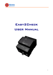
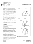
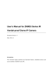
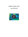
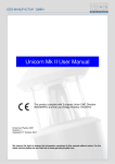
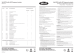
Smart Building Intercom ASK-880 System V1.6 User Manual Chapter 1 Conception Contents Chapter 1 Conception 1 Chapter 2 ASK-880 System 1 Chapter 3 Installation cautions 4 Chapter 4 System setup 7 Section 1 Outdoor camera 7 Section 2 Fence machine 8 Section 3 Decoder room number 8 Section 4 Concentrator 9 Section 5 Management center 10 Chapter 5 Common fault handling methods 12 Chapter 6 Technical support and service 13 Chapter 7 Other instructions 13 Ⅰ Building system video door phone and its project Building system video door phone is the integrated equipment which is installed in residential area, unit buildings, office buildings and other buildings. With the function of identifying visitors by pictures and voice, controlling door release and sending help messages to management center when encountering emergency situations, and the management center can also release information to the residents. Building system video door phone project is the process that combines and adjusts the building system video door phone by the means of cable transmission according to the relevant requirement of the weak current and the security project. Ⅱ How to process the building system video door phone ⅰ First of all, try to know clearly the performance, specification and installation methods of all the equipments in the building system video door phone. ⅱ Select the model and configuration for the system equipment according to the actual situation and expected function requirements of building or the complex. ⅲ Check and correct the layout and the electric environment of the building or the complex according to the configuration and installation requirements. ⅳ Install and adjust the system according to the installation instruction and relevant process standard until it is acceptance. Chapter 2 ASK-880 system Our smart building system video door phone is made up of outdoor camera, indoor monitor, decoder, management center, and other auxiliary equipments. Our outdoor camera (ASK-881) has kinds of model and function for your option according to your demands. System function and character The Maxi. capacity is 9999 indoor monitors Touch button/buton, LCD/LED display screen CCD night vision function Adapt micro computer control, simple circuit, strong function Soft plait, decoding method, no relation to the structure of building Bus line to user, foolish connection, short circuit will not affect to system 1 7P 7P 7P 7P 7P 7P 7P Password unlock IC/ID card unlock (outdoor camera should has access control function) Video and audio compatible, duplex intercom With Chinese/English message issue function With network function Red(+18V) Yellow Green White(Video) Black(GND) Brown(485+) Orange(485-) connect with the Orange of network cable connect with the Green White of network cable connect with the Green of network cable connect with the Blue of network cable connect with the Orange White and Blue White of network cable connect with the Brown of network cable connect with the Brown White of network cable All the 7P plugs in the residential area wiring connection refers to above methods. (Note: Red of 7P is power positive (+) and Black of 7P is power negative (-).) ASK-882CQ7 ASK-882CQ7 Decoder Decoder ASK-887 ASK-887 RJ 45 decoder connection: Make network crystal jack as below: ASK-882CQ7 ASK-882CQ7 ASK-882CQ7 ASK-882CQ7 Decoder IN O UT (Indoor monitor) RJ 45 connection (P 2) 1 2 3 4 5 6 7 8 Indoor monitor (RJ 45) Data 5V Audio GND Video Audio ASK-882CQ7 Network cable +18V GND ASK-882CQ7 Network cable 1 2 3 4 5 6 7 Concentrator Power supply Power supply ASK-882CQ7 Electric lock Electric lock Outdoor camera ASK-881-ⅠS-LCD ASK-882CQ7 围墙机 集线器 Electric lock ASK-882CQ7 Outdoor camera ASK-881-ⅠS-LCD ASK-882CQ7 Network cable 485+ ASK-882CQ7 Power supply 485- GND ASK-882CQ7 Video ASK-887 SPK ASK-882CQ7 Decoder MIC Control ASK-882CQ7 Decoder ASK-887 1.Orange White GND 1.Orange White 2.Orange +18V 2.Orange +18V 3.Green White Audio 3.Green White Audio Video 4.Blue Video 4.Blue 5.Blue White GND 5.Blue White GND 6.Green Audio 6.Green Audio 7.Brown White 485- 7.Brown White 5V 8.Brown 485+ 8.Brown Data Decoder(outdoor camera to decoder)IN/OUT socket Management center controller Management center GND Decoder F1-F4 socket Management center connection ASK-880 Network building video intercom connection diagram(P1) Blue Brwom White Brown to 7P to 7P to 7P to 7P to 7P Black Green Red Yellow White Orange Brown Blank Green White to 7P Blue Withe Orange to 7P 2 Green Network cable include 4 pairs of twisted cable and shielding net. Color: Brown, Brown White, Green, Green White, Blue, Blue White, Orange, orange White. Orange White Connection of flat cable decoder: 3 Outdoor camera PCB board terminals(P 3) Orange Brown 2 3 6 4 5 7 screw hole - + Power These two parts should out of wa l l socket of decoder for indoor monitor Orange Brown Black White Green Yellow Red 1 2 3 4 5 6 7 8 485485+ GND Electric lock 1 Video Audio output Audio input +18V 485485+ GND Video Audio output Audio input +18V Orange Black White Blank Control Red Brown 485+ Blank 485GND Green Yellow Video SPK MIC - + Black White Green Orange Brown Black White Green Yellow Red Brown Red Orange Yellow Black White Green 1 2 3 4 5 6 7 Yellow to indoor monitor 1 2 3 4 5 6 7 8 9 Installation as below picture: IN/OUT of decoder Red to management center or concentrator 7P flat cable(P 4) (1) 1 2 3 4 5 6 7 to next outdoor camera Data GND Video Audio input Audio output +18V Control 485+ Blank 485GND Video SPK MIC Chapter 3 Installation cautions Adjustment and problem: 1) There's a volume knob on the outdoor camera main PCB board, do not adjust the volume too loud in case that it makes Whistler. There's a volume limitation of this system indoor monitor, do not try to adjust it lead to damage the knob. 2) The wiring connection must be completely correct, otherwise, it will leads the whole s ystem o ut o f w ork. T he w rong c onnection o f t he b us l ine m ay b ring a ll o f t he indoor monitors of this building into failing to ring the bell. When encountering the above situation, please power off most of the floor protectors, and check one by one until you find out the fault. 3) When the outdoor camera calls the indoor monitor, if the outdoor camera display “CALL” and stop there, it means the bus line cut off or the yellow line is open circuit. If there is no bell ring, it means it fails to detect the indoor monitor. The reason may be the address code of the outdoor camera does not match with that of the indoor monitor. If it's abnormal or has no voice when the outdoor camera calls all the indoor monitors, maybe Outdoor camera installation (1) Installation on the door In the unit door, on the fixed side in general, choose a proper position and drill a installation hole which the size according to the outdoor camera. The distance between the ground level and the bottom of the outdoor camera is approximately 135cm. 4 P 5 5V Hole (1) use the Wafer head Self tapping screw (M3X6) to fix the seal, and then get the rear cover well fixed by using the self tapping screws (M3X6) according to the direction of the arrow. Fix the door accessories on the hole (2) by using the self tapping screws. At last, make an iron box, flanging the surroundings and fix it on the hole of the iron door, to avoid of man made destruction. Iron box as below picture: Wide Height Length P 6 (2) Installation on the wall Make a slot in the proper position of the wall, the size is the same as installation on the door (as above). The distance between the ground level and the bottom of the outdoor camera is approximately 135cm. Then put the embedded box into the slot and fix it, take care of the depth adjustment. Wall mounting Drill a hole in the wall according to the below picture, then tuck in the colloidal particle, Fix the rear cover to the wall by using the self tapping screw (M3X6), Fix it tight as the arrow direction shows, use two self tapping screws (M3X20) fix it. The 5 Wiring requirements: 1. All cables of system is adapts national standard CAT5 twisted shielded networking cable, the sectional area is equal or more than 0.5 square millimeter. 2.The sectional area of cable from power to outdoor camera and from outdoor camera to electric lock should be equal or more than 1 square millimeter, and the length should less than 15m, otherwise must enlarge the cable sectional area. 1A 4D 7G * 2B 5E 8H 0J 3C 6F # CARD Notice: Different type outdoor unit has different installation size and method P 7 I type outdoor camera embedded box II type outdoor camera embedded box I type outdoor camera embedded box Size: 306*136*45 Apply to:ASK-881 IS-LED、ASK-881 IS-LCD、ASK-E101 IS-43 II type outdoor camera embedded box Size:260 * 204 *35 Apply to:ASK-881 IIS、ASK-E101-IIS System installation cautions: 9I III type outdoor camera embedded box ·Please install outdoor camera in good visual level, supposed to be 150cm.(The height of camera lens) ·Don't install video intercom system in the following places: direct sunlight, high temperature, snow, moisture, chemical corrosion and dusty place. (Standard temperature is 0-45℃) ·Far away from the places where strong magnetic field or magnetic interference. ·Select shielded twisted pair CAT 5 for all the networking system, about shielding layer, select metal weave net. ·Shielding layer should well connected with system and handle well GND. ·Better to connect the system in series , select the iron pipe for the wiring pipe as far as possible, both ends of iron pipe have to be connect to the ground . And keep a distance of up to 50cm with high voltage cables (Such as, AC 220V, elevator wire, wired television etc) to improve anti-jamming and lightning protection ability. · For s ystem s table a nd m aintenance c onvenient, a ll n etworking c onnection j oint cannot be put inside pipe or wet place, solder joint should be handled, and packed with heat shrinkable tube, avoid of water and wet in order to make the system stable and check it conveniently. ·In outdoor unit wiring entrance should consider connect drip line. ·Do not be installed at a place where noise is over 65dB, otherwise, the noise from handset of indoor unit will be loud. ·Don't operate with power during installation. ·After all wires connected, check again and make sure that there is no mistakes then you can operate the system. · When power on, if system is in abnormal situation. Please cut off power at once until problem solved. · If system is not normal, cut off the power and check the system part by part according to <simple troubleshooting>. If cannot check out the problem, please inform agent or after-sale service department, do not repair by yourself and change parts due to system damage ·Before you use the IC or ID card for the first time on the outdoor camera with access control, you should register in the management center. III type outdoor camera embedded box Size:346 * 132 *43 Apply to:ASK-881 III、ASK-E101-III 6 7 Chapter 4 System setup Section 1 Outdoor camera Outdoor camera system setup Press “#” button first, then press “*” button, input the default password of “9999”to enter into setup interface. The outdoor camera display “P1-5”. The number 1-5 meaning as below. 1:Outdoor camera password set 2:Melody select 3:Unlock password set 4:Block number(4 digital number) 5:Delete password(restore to factory setting) Outdoor camera password set: Press “#” button first, then press “*” button, input the default password of “9999”to enter into setup interface. The outdoor camera display “P1-5”. Then input “1” to enter into password set interface. The next step is input 4 number for password. At last, press “#” button to confirm and finish the setting. Note: One system can set one password only! Outdoor camera password unlock setup Press “#” button first, then press “*” button, input “9999" for set password. The outdoor camera display “P1-5”. Please input “1” to display original password and input 4 digital new password and press “#” to finish it at once. Screen shows “OK” means set is ok. Outdoor camera unit number setup Press “#” button first, then press “*” button, input “9999" for set password. The outdoor camera display “P1-5”. Please input “4” to display original unit number and input 4 digital new nuit number and press “#” to finish it at once. Screen shows “OK” means set is ok. Outdoor camera operation 1.Password unlock: Press“#”button,input 4 digital password is ok for unlock and shows “OPEN” 2.Call indoor monitor: Input 4 digital room number(also 3 digital room number),then press “#”is ok. If input wrong number, please press “*” to clear and input new one. Delete password: Press “#” button first, then press “*” button, input the set 4 digital password. The outdoor camera display “____”and“P1-5”. Then input “5” to finish the delete of password and restore factory setting. 3.Call management center: Input “1000”, then press “#” is ok. You also can press the S1 of outdoor camera main PCB board(should open the cover) for 5 seconds to finish the delete of password and restore factory setting. Note: The system will restore factory setting after you delete the password! Melody select Press “#” button first, then press “*” button, input the default password of“9999”to enter into system setup. The outdoor camera display “P1-5”. Then input “2” to enter melody select set. You can press “2” or “8” to up and down select the melody. At last, press “#” button to confirm and finish the setting. Section 2 Fence machine The password unlock is the same as outdoor camera. The location coding method is same as outdoor camera. Section 3 Decoder room number The default room number for the port “F1--F4” of decoder is “1111”, “2222”, “3333” “4444”. You can set it as below steps. 1. 8 Connect “In”port to outdoor camera. The“OUT”port and “F1”, “F2”, “F3” 9 “F4”ports can connect or not. Power on for outdoor camera and decoder. Section 4 Concentrator 2. Press “SET” about 1.5 seconds. The decoder indicate light will off and flash. it means enter into room number set status. You can loose the “SET” button. Floor plan IN 3. Press F1 port room number, ie input “0101”, then press “# "button on the outdoor camera to finish the setup. If this port connected with indoor monitor, it will send out bell sound. At last, press “*” to hang up. The same steps for F2, F3 and F4 port. out 1 2 3 4 5 to management center or next concentrator 4.The decoder enter into normal work mode after 4 room number set within 3 seconds automatically. If you do not need set all room number, please exist set status as following three methods. The first one is press “SET” about 1.5 seconds. The indicator light will change from flash to light means restore normal work status. The second one is power off and power on for decoder. The third one is wait set over time of 60 seconds, the decoder will exist set status automatically. The order of set is from F1 to F4, should set from F1, then F2, F3. IN out 1 2 3 IN 4 5 out 1 2 3 to up concentrator to management center or next concentrator 18DCV Power 4 5 to up concentrator Note: up concentrator can connect with any “IN” port of next concentrator. If you need change the middle room number, you Concentrator connection diagram: Wiring instruction Each room number set must be finished within 60 seconds. Otherwise, it will exist set status automatically. Metal The different port can set same room number in the same decoder. If you set the same room number with different port, the all indoor monitor will ring when visitor call on the outdoor camera. The first one pick up will intercom with outdoor camera and the other ones will hang up automatically. We suggest do not set the same room number on the different decoder. If you do like this, it should all same room number ports connected with indoor monitor. Otherwise, it can not call success. And only the decoder that is the nearest to outdoor camera can get the video. If one indoor monitor answer, the others will hang up automatically. Metal Metal Metal A. Wihte Yellow : connect voltage or dry contact lock White(+) White Yellow no polarity line for voltage lock Yellow(-) B.Red Black: Power(18VDC) Red(+) polarity line Black(-) polarity line for dry contact lock 1.IN port connect bus line, port of J1、J2、J3、J4 connect with outdoor camera and fence machine when it is only single concentrator. 2.If need more than 2 concentrators, you can connect them in series. Method:make any port of J1-J4 as out port to connect with next concentrator “IN” port and so on. Management center has been set before delivery. 10 11 Section 5 Management center 3 l Be called function Management center can be called by indoor monitor, outdoor camera, fence machine. A、Be called by indoor monitor Press “Call”button on the indoor monitor. 1.LCD screen 2.Digital button 1 3.LCD screen 4.Handset 4 1 2 3 4 5 6 7 8 9 * 0 # RF ID ! 2 5 6 7 5.Contrat 6. Brightness 7.Volume Volume adjustment function When management center intercom with outdoor camera or indoor monitor, revolve the volume adjust knob to adjust hand-free volume. Operation: Recognize LCD display 3 Brightness adjust function When management center display image normally, revolve brightness adjust knob to adjust the image brightness. 3 The previous three numbers are block numbers, the latter four numbers are floor and room numbers. Unit number Room number (management center call indoor monitor) Unit numbers 0000 (management center call outdoor camera) 3 Contrast adjust function When management center displays outdoor camera image normally, revolve contrast adjust knob to adjust the image contrast. Chapter 5 Common fault handling methods 3 Unit number Room number management center display) Unit number 0000 management center display) (Indoor monitor call management center, (Outdoor camera call management center, Call function Management center can call indoor monitor, monitor outdoor camera and other fence machines. A. Management center call indoor monitor If the unit system of be called indoor monitor is free (not busy), input unit and room numbers of this indoor monitor on the management center. (total is 8 numbers). Then press “#” button, the management center can intercom with indoor monitor. B. Management center surveillance outdoor camera If the called outdoor camera is free (not busy), input unit number and “0000”, then press “#” button, the management center screen open and display the video of outdoor camera. 12 B.Outdoor camera call management center Input “1000” on outdoor camera, then press “#” button to call management center (If it is direct-press outdoor camera, press “management center” button.). The management center will display unit number of outdoor camera + “0000” and ring a sound of “Ding-Dong”. The management center can intercom with outdoor camera after offhook. Meanwhile the outdoor camera outside image is displayed on management center screen, and press “unlock” button to open the lock of the calling outdoor camera. 1. Can not unlock(Intercom is normal) Fault coverage: unlock circuit Fault remove and analysis a) Check the line from outdoor camera to electronic lock b) Check L+, L- whether has about 12V voltage output to electronic lock or not c) Check electronic lock coil is damaged or not 2.Outdoor camera can not call indoor monitor Fault coverage: A. Decoder without encode room number B. Orange and brown line connect wrong C. The cable from decoder to indoor monitor is not connect well D. The distance from decoder to indoor monitor(it is45 meter by using CAT5 cable), if it is more than 45 meters, you should connect blue white line to GND 13 3. Have image, no voice Fault coverage: intercom circuit Fault analysis: confirm one unit or whole system problem Whole system: a) Check the Yellow and Green line of outdoor camera connect wrong or not b) Check outdoor camera intercom circuit One unit: check the Yellow and Green line from decoder to indoor monitor connect wrong or not 4. Monitor and no image Fault coverage: A. Video line(Blue line of network cable) B. Check CCD jack C .If “Calling” is abnormal, the same as point 2 Chapter 7 Other Instructions Transportation: This products should be transport in the condition of good package, do not transport unpacked. Avoid of sun light, water, dust and mechanical damage. Statement Although our product is a kind of advanced alarm equipment, but if there is artificial damage or system failure will influence system work. According to the alarm information from this equipment, only can reduce suffer loss from theft, rob, fire, gas leak etc, but not guarantee no mistake. Our company assume no responsibility of user's suffer loss from theft, fire etc. for relative reason to claim for compensation from our company. The maximum compensation limit is less than products prices. 5. Button is out of work Fault coverage: A. System power B. Main PCB board C. Contact with manufacturer Chapter 6 Technical support and service 1.Our products insist on pre-sale, sale, after-sale service policy in the whole process. Before confirm the project solution, please read this manual instruction carefully, then consult and confirm with technical person of our branch office or agent, large area networking or special project can consult directly with head office technical support center. 2.When install and adjustment these products, please conduct according to this manual instruction strictly. If there is difficulty, please contact with our branch office or agent. For special problem, please contact with our technical person of head office. 3.The explanation rights of this manual instruction is own to our company. Any question in the process of using on engineering guidance, please call our market service center 14 15