1
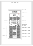
ATUPT1K0EO & ATUPT1K0EO1D USER MANUAL Manufactured by R.V.R ELETTRONICA S.p.A. Italy File Name: ATUPT1K0EO& ATUPT1K0EO1D_ING_1.0.indb Version: 1.0 Date: 23/07/2012 Revision History Date Version 23/07/2012 1.0 Reason First Version Editor J. H. Berti ATUPT1K0EO & ATUPT1K0EO1D - User Manual Version 1.0 © Copyright 2012 R.V.R. Elettronica SpA Via del Fonditore 2/2c - 40138 - Bologna (Italia) Telefono: +39 051 6010506 Fax: +39 051 6011104 Email: [email protected] Web: www.rvr.it All rights reserved Printed and bound in Italy. No part of this manual may be reproduced, memorized or transmitted in any form or by any means, electronic or mechanic, including photocopying, recording or by any information storage and retrieval system, without written permission of the copyright owner. ATUPT1K0EO & ATUPT1K0EO1D ELETTRONICA DECLARATION OF CONFORMITY We, the undersigned, Manufacturer’s Name: R.V.R. Elettronica SpA Manufacturer’s Address: Via del Fonditore 2/2c I - 40138 Bologna Italy Certify and declare under our sole responsibility that the product: Product Description: Solid State Transmitter Station for analog TV broadcasting Modulation: PAL Standard UHF Band Model: ATUPT1K0EO Variant: ATUPT1K0EO1D Frequency Range: 470.000 ÷ 862.000 MHz RF Power Output: 100 ÷ 1000 WPS when used for its intended purpose, is in compliance with the essential requirements and other relevant provisions of Directive 99/5/CE “R&TTE”, and therefore carries the “CE” mark. The conformity assessment procedure referred in Article 10 and detailed in Annex III of Directive 99/5/EC has been followed. The following harmonized standard have been applied: Radio (3.2): EN 302 397 EMC (3.1b): EN 301 489 - 1 + EN 301 489 - 11 Safety (3.1a): EN 60215 + EN 60065 The technical documentation is held at the location above, as required by the conformity assessment procedure. Bologna, Italy, 03/09/2009 Ravagnani Stefano Technical Manager R.V.R Elettronica S.p.A. User Manual Rev. 1.0 - 23/07/12 ATUPT1K0EO & ATUPT1K0EO1D ELETTRONICA Technical Specification Frequency range: Nominal RF power: Power supply voltage: Nominal exciting power: Consumption: ii Rev. 1.0 - 23/07/12 UHF IV&V band 470 to 862 MHz 1000 WPS (PAL Standard ) 220Vac about 1W about 2kW User Manual ELETTRONICA ATUPT1K0EO & ATUPT1K0EO1D Table of Contents 1. 2. 3. 3.1 3.2 4. 4.1 5. 5.1 5.2 6. 6.1 6.2 6.3 Preliminary Instructions Warranty First Aid Electric shock treatment Treatment of electric burns General Description Composition Installation and Use Installation First Start Equipment Quick Reference Exciter (ATVTE) Amplifier (ATVCA) Changeover (SCML1+1SL) User Manual Rev. 1.0 - 23/07/12 1 1 2 2 2 3 3 5 5 5 7 7 7 8 iii ATUPT1K0EO & ATUPT1K0EO1D ELETTRONICA This page was intentionally left blank iv Rev. 1.0 - 23/07/12 User Manual ATUPT1K0EO & ATUPT1K0EO1D ELETTRONICA IMPORTANT The symbol of lightning inside a triangle placed on the product, evidences the operations for which is necessary gave it full attention to avoid risk of electric shocks. The symbol of exclamation mark inside a triangle placed on the product, informs the user about the presence of instructions inside the manual that accompanies the equipment, important for the efficacy and the maintenance (repairs). Make sure both are properly connected. 1. Preliminary Instructions Operation of this equipment in a residential area may cause radio interference, in which case the user may be required to take adequate measures. • General Warnings This equipment should only be operated, installed and maintained by “trained” or “qualified” personnel who are familiar with risks involved in working on electric and electronic circuits. “Trained” means personnel who have technical knowledge of equipment operation and who are responsible for their own safety and that of other unqualified personnel placed under their supervision when working on the equipment. “Qualified” means personnel who are trained in and experienced with equipment operation and who are responsible for their own safety and that of other unqualified personnel placed under their supervision when working on the equipment. The specifications and data contained herein are provided for information only and are subject to changes without prior notice. R.V.R. Elettronica S.p.A. disclaims all warranties, express or implied.While R.V.R. Elettronica S.p.A. attempts to provide aamplifierrate information, it cannot accept responsibility or liability for any errors or inaamplifierracies in this manual, including the products and the software described herein. R.V.R. Elettronica S.p.A. reserves the right to make changes to equipment design and/or specifications and to this manual at any time without prior notice. • Notice concerning product intended purpose and use limitations. WARNING: Residual voltage may be present inside the equipment even when the ON/OFF switch is set to Off. Before servicing the equipment, disconnect the power cord or switch off the main power panel and make sure the safety earth connection is connected. Some service situations may require inspecting the equipment with live circuits. Only trained and qualified personnel may work on the equipment live and shall be assisted by a trained person who shall keep ready to disconnect power supply at need. R.V.R. Elettronica S.p.A. shall not be liable for injury to persons or damage to property resulting from improper use or operation by trained/untrained and qualified/unqualified persons. WARNING: The equipment is not water resistant. Any water entering the enclosure might impair proper operation. To prevent the risk of electrical shock or fire, do not expose this equipment to rain, dripping or moisture. Please observe local codes and fire prevention rules when installing and operating this equipment. WARNING: This equipment contains exposed live parts involving an electrical shock hazard. Always disconnect power supply before removing any covers or other parts of the equipment. Ventilation slits and holes are provided to ensure reliable operation and prevent overheating; do not obstruct or cover these slits. Do not obstruct the ventilation slits under any circumstances. The product must not be incorporated in a rack unless adequate ventilation is provided or the manufacturer’s instructions are followed closely. WA R N I N G : T h i s e q u i p m e n t c a n r a d i a t e radiofrequency energy and, if not installed in compliance with manual instructions and applicable regulations, may cause interference with radio communications. WARNING: This equipment is fitted with earth connections both in the power cord and for the chassis. User Manual This product is a radio transmitter suitable for frequencymodulation audio radio broadcasting. Its operating frequencies are not harmonised in designated user countries. Before operating this equipment, user must obtain a licence to use radio spectrum from the competent authority in the designated user country. Operating frequency, transmitter power and other characteristics of the transmission system are subject to restrictions as specified in the licence. 2. Warranty La R.V.R. Elettronica S.p.A. warrants this product to be free from defects in workmanship and its proper operation subject to the limitations set forth in the supplied Terms and Conditions. Please read the Terms and Conditions carefully, as purchase of the product or acceptance of the order acknowledgement imply acceptance of the Terms and Conditions. For the latest updated terms and conditions, please visit our web site at WWW.RVR.IT. The web site may be modified, removed or updated for any reason whatsoever without prior notice. The warranty will become null and void in the event the product enclosure is opened, the product is physically damaged, is repaired by unauthorised persons or is used for purposes other than its intended use, as well as in the event of improper use, unauthorised changes or neglect. In the event a defect is found, follow this procedure: 1 Contact the seller or distributor who sold the equipment; provide a description of the problem or malfunction for the event a quick fix is available. Sellers and Distributors can provide the necessary information to troubleshoot the most frequently encountered problems. Normally, Sellers and Distributors can offer a faster repair service than the Manufacturer would. Please note that Sellers can pinpoint problems due to wrong installation. 2 If your Seller cannot help you, contact R.V.R. Elettronica S.p.A. and describe the problem; if our staff deems it appropriate, you will receive an authorisation to return the equipment along with suitable instructions; 3 When you have received the authorisation, you may return the unit. Pack the unit carefully before shipment; use the original packaging whenever possible and seal the package perfectly. The customer bears all risks of loss (i.e., R.V.R. shall not be liable for loss or damage) until the package reaches the R.V.R. factory. For this reason, we recommend insuring the goods for their full value. Returns must be sent on a C.I.F. basis (PREPAID) to the address stated on the authorisation as specified Rev. 1.0 - 23/07/12 / 10 ATUPT1K0EO & ATUPT1K0EO1D by the R.V.R. Service Manager. Figure 3 Figure 4 Figure 5 Units returned without a return authorisation may be rejected and sent back to the sender. • One rescuer: give 2 quick rescue breaths after each 15 compressions. 4 Be sure to include a detailed report mentioning all problems you have found and copy of your original invoice (to show when the warranty period began) with the shipment. • Two rescuers: one rescue breath after each 5 compressions. • Do not stop chest compressions while giving artificial breathing. • Call for medical help as soon as possible. Please send spare and warranty replacement parts orders to the address provided below. Make sure to specify equipment model and serial number, as well as part description and quantity. ELETTRONICA R.V.R. Elettronica S.p.A. Via del Fonditore, 2/2c 40138 BOLOGNA ITALY Tel. +39 051 6010506 3.1.2 3. First Aid All personnel engaged in equipment installation, operation and maintenance must be familiar with first aid procedures and routines. 3.1 Electric shock treatment 3.1.1 If the victim is unconscious If the victim is conscious • Cover victim with a blanket. • Try to reassure the victim. • Loosen the victim’s clothing and have him/her lie down. • Call for medical help as soon as possible. 3.2 Treatment of electric burns 3.2.1 Large burns and broken skin • Cover affected area with a clean cloth or linen. • Do not break any blisters that have formed; remove any clothing or fabric that is stuck to the skin; apply adequate ointment. • Administer adequate treatment for the type of accident. • Get the victim to a hospital as quickly as possible. • Elevate arms and legs if injured. Follow the first aid procedures outlined below. • Lay the victim down on his/her back on a firm surface. • the neck and tilt the head backwards to free the airway system (Figure 1). If medical help is not available within an hour, the victim is conscious and is not retching, administer a solution of table salt and baking soda (one teaspoon of table salt to half teaspoon of baking soda every 250 ml of water). Have the victim slowly drink half a glass of solution for four times during a period of 15 minutes. Figure 1 • If needed, open the victim’s mouth and check for breathing. • If there is no breathing, start artificial respiration without delay (Figure 2) as follows: tilt the head backwards, pinch the nostrils, seal your mouth around the victim’s mouth and give four fast rescue breaths. Stop at the first sign of retching. Do not administer alcoholic beverages. 3.2.2 Minor burns Figure 2 • / 10 Check for heartbeat (Figure 3); if there is no heartbeat, begin chest compressions immediately (Figure 4) placing your hands in the centre of the victim’s chest (Figure 5). Rev. 1.0 - 23/07/12 • Apply cold (not ice cold) strips of gauze or dress wound with clean cloth. • Do not break any blisters that have formed; remove any clothing or fabric that is stuck to the skin; apply adequate ointment. • If needed, have the victim change into clean, dry clothing. • Administer adequate treatment for the type of accident. • Get the victim to a hospital as quickly as possible. • Elevate arms and legs if injured. User Manual ATUPT1K0EO & ATUPT1K0EO1D ELETTRONICA 4. General Description The ATUPT1K0EO & ATUPT1K0EO1D are RF solid-state transmitter for PAL analog TV broadcasting , manufactured by R.V.R. Elettronica S.p.A. with 1000WPS of maximum power output. It is fully solid-state apparatus of modern design that uses MOSFET as active components in the TV amplifying modules. This chapter briefly describes the machine’s main features. 4.1 Composition The ATUPT1K0EO is made up: 1 ATVTE005PU1 exciter 1 ATVCA1K0LU1 amplifier User Manual Rev. 1.0 - 23/07/12 / 10 ATUPT1K0EO & ATUPT1K0EO1D ELETTRONICA The ATUPT1K0EO1D is made up: 2 ATVTE005PU1 exciter 1 SCML1+1SL changeover 1 ATVCA1K0LU1 amplifier The standard configuration of the ATUPT1K0EO & ATUPT1K0EO1D foresees one 19” rack (see figure). The manufacturer will produce upon customers request special configurations. The amplifier is supplied complete with all its parts, not really “modules”, essential for its operation such as the fans for dissipating the heat generated by the machine inside the room and all the accessories for the electrical and RF wiring. As a rule, the amplifier is supplied as a complete transmitter therefore the two TV exciters that it manages will be provided and connected (a service exciter and a spare exciter). Note: This manual gives system-level information about the ATUPT1K0EO & ATUPT1K0EO1D. Further details about the operation of the single components please refer to the relative manuals, that are attached to the present one and should be considered a part of it: • STU05 (alias ATVTE) • ATVCA1K0LU1 • SCML1+1SL / 10 Rev. 1.0 - 23/07/12 User Manual ATUPT1K0EO & ATUPT1K0EO1D ELETTRONICA 5. Installation and Use This chapter contains the basic instructions for installing and using the ATUPT1K0EO & ATUPT1K0EO1D. If necessary, more depth information about the operating principles may be found in the components’ manuals. 5.1 Installation For practical reasons and for transport safety, the machine can be supplied disassembled to the customer. The assembly procedure is rather simple and can be carried out by any qualified technician. Note: In order to avoid the risk of damaging the machine and/or of injuring the operators, it is advisable to closely adhere to the instructions provided below. always respect all the safety regulations and standards in force. Unpack the transmitter and before any other operation check that the equipments hasn’t been damaged during transport and all the controls and connectors on the front and rear panels are in good condition. To install the ATUPT1K0EO & ATUPT1K0EO1D transmitter please refer to the relative technical dossier, particularily about: • Mains supply connection • RF connections Perform the connections following the instructions and schematics given in the station’s documentation (technical dossier). 5.2 First Start This section describes the procedure for powering-on the machine the first time. For a description of the power up procedure of the single amplifiers in the different cases, of the use of the exciters and of the hybrid combiner, please consult the relative manuals. 5.2.1 Preliminary Operations Before activating the apparatus, please perform the necessary connections, that is: • Power supply • Modulating signals • RF amplifier section and load User Manual Rev. 1.0 - 23/07/12 / 10 ATUPT1K0EO & ATUPT1K0EO1D ELETTRONICA It is advisable to run the first tests connecting the transmitter to a suitable (for type and power) dummy load rather than to the transmission antenna. 5.2.2 Power-on When powering-on the transmitter the first time, perform the operations below to work efficiently in less time as possible. • Switch on the service mains supply. • Keeping the exciter at its minumum power level. When power up, the ATVTE exciter display reports the frequency and power level; if these are not as required, just switch it in OFF mode to temporarily deactivate the power output. • Switch on the mains power supply for all amplifiers. • Enable the exciter currently connected to the amplifier and check the working frequency. If necessary changed it. • Rise its output power until the output power of the amplifier (the overall power indicated on Amplifier unit display) reaches its required value indicated in technical dossier. Note: during the RF output power rising, check the reflected power level (on amplifier unit) to verify the antenna status. The transmitter is now up and running at its nominal power level. It is then possible to perform all the controls and verification that one thinks are necessary before putting it into operation. / 10 Rev. 1.0 - 23/07/12 User Manual ATUPT1K0EO & ATUPT1K0EO1D ELETTRONICA 6. Equipment Quick Reference 6.1 Exciter (ATVTE) Note: not change the frequency until you have properly calibrated the output filter. • Set the exciters following the instructions of the exciters that you are used to set the desired operating frequency. Adjust the output power of exciter to the power required to drive your transmitter. Before that you enable the delivered power from exciter, it is suggested to check and, in case, correct the basic parameters under own necessity: • • frequency power 6.2 Amplifier (ATVCA) • Adjust the power of each amplifier through setting menu (SET); the overall RF output emitted by transmitter appears on the power meter display, if it is present. User Manual Rev. 1.0 - 23/07/12 / 10 ATUPT1K0EO & ATUPT1K0EO1D ELETTRONICA 6.3 Changeover (SCML1+1SL) • Set the changeover between exciters following the instructions below, if it is present. Before that you enable the delivered power from main exciter, it is suggested to check and, in case, correct the basic parameters under own necessity: • • local/remote status changeover Note: Some information here contained may be not necessary for the proper functioning of your transmitter. Note: turning the encoder, the cursor moves itself on indicators of the various sub-menus, while in the middle of the window it shows the contents. If you press the encoder while the indicator of a menu is highlighted on navigation bar, and if it contains adjustable parameters, the cursor moves within the central window of the display, allowing you to act on adjustable parameters. Every menu contains a “EXIT” field: by pressing the encoder while this field is highlighted, you will leave the submenu and return to navigation mode. • Set the LOCAL/REMOTE switch to LOCAL position through General Setting menu using MODE function, this is to enable local control of changeover. The respective LED lights on for confirmation. TX1 : ON TX2 : OFF Change: Normal Func. : AUTO Mode : REMOTE Reset : OK IIC : 10 Exit / 10 Rev. 1.0 - 23/07/12 User Manual ELETTRONICA ATUPT1K0EO & ATUPT1K0EO1D • Set the changeover between the exciters through General Setting menu using CHANGE function. The respective LED lights on for confirmation. Note: all changes made will be briefly described by synoptic, which includes a series of LED for the instantaneous vision of the exchange condition. It shows the position of coaxial relay, the state of dummy load and of transmitter connects to it. User Manual Rev. 1.0 - 23/07/12 / 10 ATUPT1K0EO & ATUPT1K0EO1D ELETTRONICA This page was intentionally left blank 10 / 10 Rev. 1.0 - 23/07/12 User Manual ______________________________________________________________________________ ______________________________________________________________________________ ______________________________________________________________________________ ______________________________________________________________________________ ______________________________________________________________________________ ______________________________________________________________________________ ______________________________________________________________________________ ______________________________________________________________________________ ______________________________________________________________________________ ______________________________________________________________________________ ______________________________________________________________________________ ______________________________________________________________________________ ______________________________________________________________________________ ______________________________________________________________________________ ______________________________________________________________________________ ______________________________________________________________________________ ______________________________________________________________________________ ______________________________________________________________________________ ______________________________________________________________________________ ______________________________________________________________________________ ______________________________________________________________________________ ______________________________________________________________________________ ______________________________________________________________________________ ______________________________________________________________________________ ______________________________________________________________________________ ______________________________________________________________________________ ______________________________________________________________________________ ______________________________________________________________________________ ______________________________________________________________________________ ______________________________________________________________________________ ______________________________________________________________________________ ______________________________________________________________________________ ______________________________________________________________________________ ______________________________________________________________________________ ______________________________________________________________________________ ______________________________________________________________________________ ______________________________________________________________________________ ______________________________________________________________________________ ______________________________________________________________________________ ______________________________________________________________________________ ______________________________________________________________________________ ______________________________________________________________________________ ______________________________________________________________________________ ______________________________________________________________________________ ______________________________________________________________________________ ______________________________________________________________________________ ______________________________________________________________________________ ______________________________________________________________________________ ______________________________________________________________________________ ______________________________________________________________________________ ______________________________________________________________________________ ______________________________________________________________________________ ______________________________________________________________________________ ______________________________________________________________________________ ______________________________________________________________________________ ______________________________________________________________________________ ______________________________________________________________________________ ______________________________________________________________________________ ______________________________________________________________________________ ______________________________________________________________________________ ______________________________________________________________________________ ______________________________________________________________________________ ______________________________________________________________________________ ______________________________________________________________________________ ______________________________________________________________________________ ______________________________________________________________________________ ______________________________________________________________________________ ______________________________________________________________________________ ______________________________________________________________________________ ______________________________________________________________________________ ______________________________________________________________________________ ______________________________________________________________________________ ______________________________________________________________________________ ______________________________________________________________________________ ______________________________________________________________________________ R.V.R Elettronica S.p.A. Via del Fonditore, 2 / 2c Zona Industriale Roveri · 40138 Bologna · Italy Phone: +39 051 6010506 · Fax: +39 051 6011104 e-mail: [email protected] ·web: http://www.rvr.it ISO 9001:2000 certified since 2000 The RVR Logo, and others referenced RVR products and services are trademarks of RVR Elettronica S.p.A. in Italy, other countries or both. RVR ® 1998 all rights reserved. All other trademarks, trade names or logos used are property of their respective owners.