1
2-2
Start Up
Applying Power to the Drive
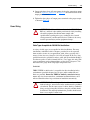
❏ 4. Apply AC power and control voltages to the drive.
If any of the six digital inputs are configured to “Stop – CF” (CF = Clear
Fault) or “Enable,” verify that signals are present or reconfigure [Digital
Inx Sel]. If an I/O option is not installed (i.e. no I/O terminal block),
verify that [Digital Inx Sel] is not configured to “Stop – CF” or “Enable.”
If this is not done, the drive will not start. Refer to Alarm Descriptions on
page 4-6 for a list of potential digital input conflicts. If a fault code
appears, refer to Chapter 4.
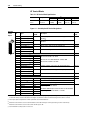
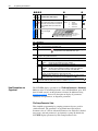
If the STATUS LED is not flashing green at this point, refer to LED
Status Definitions in Table 2.A.
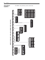
❏ 5. Proceed to Start-Up Routines.
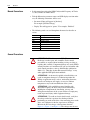
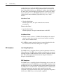
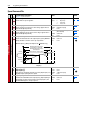
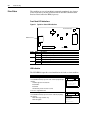
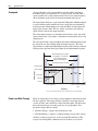
Status Indicators
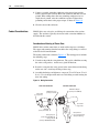
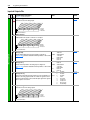
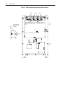
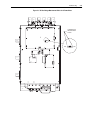
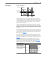
Figure 2.1 Drive Status Indicator
Inverter
Status LED
Control Panel
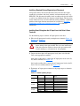
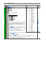
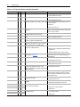
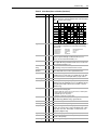
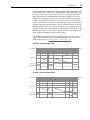
Table 2.A Ready LED Status Indications
Color
Green
Yellow
See page 4-2.
State
Flashing
Steady
Flashing
Steady
Red
See page 4-3.
Flashing
Steady
Description
Drive ready, but not running and no faults are present.
Drive running, no faults are present.
The drive is not ready. Check parameter 214 [Start Inhibits].
An alarm condition exists. Check parameters 211 [Drive Alarm 1]
and 212 [Drive Alarm 2].
A fault has occurred.
A non-resettable fault has occurred.