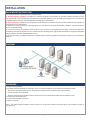
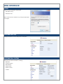
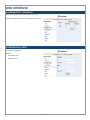
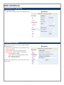
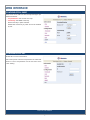
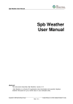
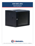
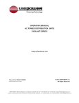
1
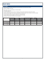
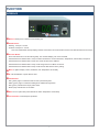
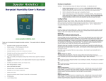
ANI-15115-08MTH
PDU: Total Current Monitoring
INSTRUCTION MANUAL
122 Rose Ln., Suite 303, Frisco, Texas 75034 | TOLL FREE: 1-877-ANEUTRON | TOLL: (469) 362-9228 | Email: [email protected] | A-Neutronics.com
SAFETY INFORMATION
1. To ensure the best results from this product, please read this manual and all other documentation before operating your equipment.
Retain all documentation for future reference.
2. Follow all instructions printed on unit chassis for proper operation.
3. To reduce the risk of fire, do not spill water or other liquids into or on the unit, or operate the unit while standing in liquid.
4. Make sure power outlets conform to the power requirements listed on the back of the unit. Keep unit protected from rain, water and
excessive moisture.
5. Do not attempt to clean the unit with chemical solvents or aerosol cleaners, as this may damage the unit. Dust with a clean dry cloth.
6. Do not use the unit if the electrical power cord is frayed or broken. The power supply cords should be routed so that they are not
likely to be walked on or pinched by items placed upon or against them, paying particular attention to cords and plugs, convenience
receptacles, and the point where they exit from the appliance.
7. Do not force switched or external connections in any way. They should all connect easily, without needing to be forced.
8. Always operate the unit with the AC ground wire connected to the electrical system ground. Precautions should be taken so that the
means of grounding of a piece of equipment is not defeated.
9. AC voltage must be correct and the same as that printed on the rear of the unit. Damage caused by connection to improper AC
voltage is not covered by any warranty.
10. Turn power off and disconnect unit from AC current before making connections.
11. Never hold a power switch in the “ON” position.
12. This unit should be installed in a cool dry place, away from sources of excessive heat, vibration, dust, moisture and cold. Do not use
the unit near stoves, heat registers, radiators, or other heat producing devices.
13. Do not block fan intake or exhaust ports. Do not operate equipment on a surface or in an environment which may impede the normal
flow of air around the unit, such as a bed, rug, carpet, or completely enclosed rack. If the unit is used in an extremely dusty or smoky
environment, the unit should be periodically “blown free” of foreign dust and matter.
14. To reduce the risk of electric shock, do not remove the cover. There are no user serviceable parts inside. Refer all servicing to
qualified service personnel. There are no user serviceable parts inside.
15. When moving the unit, disconnect input ports first, then remove the power cable; finally, disconnect the interconnecting cables to
other devices.
16. Do not drive the inputs with a signal level greater than that required to drive equipment to full output.
17. The equipment power cord should be unplugged from the outlet when left unused for a long period of time.
18. Save the carton and packing material even if the equipment has arrived in good condition. Should you ever need to ship the unit,
use only the original factory packing.
19. Service Information Equipment should be serviced by qualifier service personnel when:
A. The power supply cord or the plug has been damaged.
B. Objects have fallen, or liquid has been spilled into the equipment.
C. The equipment has been exposed to rain
D. The equipment does not appear to operate normally, or exhibits a marked change in performance
E. The equipment has been dropped, or the enclosure damaged.
THIS SAFETY INFORMATION IS OF A GENERAL NATURE AND MAY BE SUPERSEDED BY INSTRUCTIONS CONTAINED WITHIN THIS MANUAL
TABLE OF CONTENTS
CONTENTS
SAFETY PRECAUTIONS
Introduction .....................................................................1
Features ......................................................................... 2
Function .......................................................................... 3
Installation ....................................................................... 4
Web Interface ................................................................... 5
Please read all instructions before attempting to unpack, install or
operate this equipment and before connecting the power supply.
Please keep the following in mind as you unpack and install this
equipment:
• Always follow basic safety precautions to reduce the risk of fire,
electrical shock and injury to persons.
• To prevent fire or shock hazard, do not expose the unit to rain,
moisture or install this product near water.
INTRODUCTION
• Never spill liquid of any kind on or into this product.
The PDU is an Internet ready device designed and equipped
with an intelligent current-meter (True RMS) that will indicate
the total power consumption of the power strip. The PDU offers
an easy set up and user-friendly communication software. This
software provides the ability to remotely monitor and evaluate
current power consumption.
• Never push an object of any kind into this product through any
openings or empty slots in the unit, as you may damage parts
inside the unit.
INCLUDED
• To protect the unit from overheating, do not block any vents or
openings in the unit housing that provide ventilation and allow for
sufficient space for air to circulate around the unit.
• Do not attach the power supply cabling to building surfaces.
• Use only the supplied power supply unit (PSU). Do not use the
PSU if it is damaged.
• Do not allow anything to rest on the power cabling or allow any
weight to be placed upon it or any person walk on it.
The standard PDU package contains a Power Distribution Unit
with supporting hardware. The components of the package are:
• Power Distribution Unit
DISCLAIMERS
• Rack mount Brackets (rack screws not provided)
• Quick Start Guide
The information in this manual has been carefully checked and
is believed to be accurate. We assume no responsibility for any
infringements of patents or other rights of third parties which
may result from its use.
AVAILABLE FOR DOWNLOAD
MIB: Management Information Base for Network.
We assume no responsibility for any inaccuracies that may be
contained in this document. We make no commitment to update
or to keep current the information contained in this document.
http://www.a-neutronics.com/Software/ANI-15115-08xxx_MIB.zip
PDU Software: PDU Utility zip file.
http://www.a-neutronics.com/Software/ANI-15115-08xxx_PDU-Utility.zip
We reserve the right to make improvements to this document
and/or product at any time and without notice.
Or visit our website A-Neutronics.com to download directly
from the product page.
COPYRIGHT NOTICE
No part of this document may be reproduced, transmitted,
transcribed, stored in a retrieval system, or any of its part translated
into any language or computer file, in any form or by any means
— electronic, mechanical, magnetic, optical, chemical, manual,
or otherwise — without express written permission and consent
© Copyright 2015. All Rights Reserved.
Version 1.2 DEC 2014
TRADEMARK ACKNOWLEDGMENTS
All products or service names mentioned in this document may
be trademarks of the companies with which they are associated.
1
FEATURES
FEATURES
• Built-in web server manager monitors the current consumption of the power strip in real time
• Built-in true RMS current meter.
• Easy setup, meter can read directly or VIA the IP address.
• Homepage support SSL.
• Provides audible alarm when the power consumption goes beyond the threshold of warning and overload.
• Sends an email and traps when the power consumption exceeds the trigger value of warning or overload to the PDU.
• Provided software utility, it can monitor multiple PDU’s at the same time.
• Supports SNMP and provides MIB for the PDU to be monitored by NMS.
• Provide per outlet power protection by the circuit breaker.
PER OUTLET
CONTROL
ANI-15115-08MTH
TOTAL PDU
CURRENT
MONITORING
PER OUTLET
CURRENT
MONITORING
TIME SCHEDULE
PER OUTLET
P
P
TIME
TEMPERATURE
REFERENCE VIA
& HUMIDTY
TIME SERVER
OPTION
P
ANI-15115-08SWH
P
P
ANI-15115-08MSH
P
P
2
P
P
Function
Interface
qEthernet: RJ45 port for network communication port.
wAudible Alarm:
• Warning- 1 beep in 1 second.
• Overload- 3 beeps in 1 second.
Note: The audible alarm will keep beeping until the current returns to normal and the current is lower than the threshold of 0.5 amps.
eFunction Button:
• Press and release to turn off the warning beep. The overload beeping can not be cancelled.
• Hold the button and release after 1 beep. The meter will show the current information, *temperature, and humidity in sequence.
• Hold the button and release after 2 beeps. The meter will show the IP address.
• Hold the button and release after 4 beeps. It will change the IP from DHCP or fixed IP.
• Hold the button and release after 6 beeps. It will reset the PDU back to factory setting.
rMeter: 3 digits to display current, IP Address, and *temperature and humidity
tID: The identification of power bank or PDU.
yLED Indicator:
• SSL (yellow): Light on means that web access is protected by SSL.
• DHCP (green): Light on means that PDU gets IP address through DHCP.
• PDU (green): Indicate each output power status.
• Status (red): Indicate each circuit status.
uENV: RJ11 for option ENV probe attached to detect *temperature and humidity.
iCircuit Breaker: Overload power protection.
3
Installation
Rack Mount Instructions
This section will provide a quick instruction to install the PDU.
A. Elevated Operating Ambient: If installed in a closed or multi-unit rack assembly, the operating ambient temperature of the
rack environment may be greater than room ambient. Consideration should be given to installing the equipment in an environment
compatible with the maximum ambient temperature specified by the manufacturer.
B. Reduced Air Flow: Installation of the equipment in a rack should be such that the amount of air flow required for safe operation of
the equipment is not compromised.
C. Mechanical Loading: Mounting of the equipment in the rack should be such that a hazardous condition is not achieved due to
uneven mechanical loading.
D. Circuit Overloading: Consideration should be given to the connection of the equipment to the supply circuit and the effect that
overloading of the circuits might have on over current protection and supply wiring. Appropriate consideration of equipment nameplate
ratings should be used when addressing this concern.
E. Reliable Grounding: Installation should be in accordance with all governing entities to include but not limited to your local electric
code, etc.
Diagram
Hardware
1. Install mounting brackets.
2. The PDU comes with brackets for mounting in a rack. To mount the PDU into a rack perform the following procedure:
• Attach the mounting brackets to the unit, using the four retaining screws provided for each of the brackets.
• Choose a location for the brackets.
• Align the mounting holes of brackets with the notched hole on the vertical rail and attach with the retaining screws.
3. Connect input and output power.
4. Connect Ethernet cable to the PDU.
5. Switch on the PDU.
Note 1: The default setting IP address is DHCP. If PDU can not get the IP address from DHCP server, the IP address will stay at
192.168.0.216
4
Web Interface
Login
Input the PDU IP address in web browser.
• User Name: snmp
• Password: 1234
Note: Screen shots for reference only. Actual prompts might
vary slightly.
Information: PDU
Displays total PDU and each outlet power consumption.
Information: System
Indicates PDU system information, including:
• Model No.
• Firmware Version
• MAC Address
• System Name
• System Contact
• Location
5
Web Interface
Configuration: Threshold
Set the warning and overload threshold for each circuit.
Set lower and upper threshold for *temperature and humidity.
Configuration: User
Change ID and password.
Default is:
• User Name: snmp
• Password: 1234
6
Web Interface
Configuration: Network
PDU network information
• Enable DHCP: Change the way to get IP address for PDU.
Configuration: Mail
When event occurs, PDU can send out an email message to
pre-defined account.
• Email Server: The Email Server only supports the domain
name, not IP address.
• Sender’s Email: Input the sender email address.
• Email Address: Input the recipient email address.
The message in the email:
Indicate OutletA~H-XXXXXXXX status in order
X=0 : means the power off.
X=1 : means the power on.
Note: Make sure DNS server can resolve the Email Server’s
domain name.
7
Web Interface
Configuration: SNMP
When event occurs, PDU can send out trap message to predefined IP address.
• Trap Notification: Set receiver IP for trap.
• Community: Set SNMP community.
Read Community is public and fixed.
Default Write Community is “public” and can be modified
by user.
Configuration: SSL
Enable SSL for web communication.
User must input the correct ID and password to enable SSL
function. The ID and password must be the same as the
“User” Setting.
END OF DOCUMENT
8