1
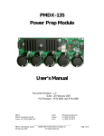
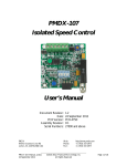
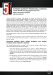
PMDX Optical Sensors
User’s Manual
Document Revision: 0.4
Date: 15 May 2006
PMDX
7432 Alban Station Blvd., A105
Springfield, VA 22150-2321 USA
Web:
Phone:
FAX:
http://www.pmdx.com
+1 (703) 912-4991
+1 (703) 912-5849
PMDX_Sensor_Manual_04.doc ©2005-2006, Practical Micro Design, Inc.
15 May 2006
All Rights Reserved
Page 1 of 9
PMDX Optical Sensors User’s Manual
Document Revision: 0.4
Table of Contents
1.0
Overview .................................................................................................................................3
1.1
Important Safety Information ........................................................................................................................ 3
1.2
Warranty Summary......................................................................................................................................... 3
1.3
Features ............................................................................................................................................................. 4
1.4
Updates to this Manual................................................................................................................................... 4
2.0
Installation and Operation.....................................................................................................4
2.1
General Operating Constraints .................................................................................................................... 4
2.2
Slotted Sensor .................................................................................................................................................. 5
2.2.1
Slotted Sensor Output Signal ............................................................................................................... 5
2.3
Reflective Sensor ............................................................................................................................................. 5
2.3.1
Reflective Sensor Output Signal .......................................................................................................... 5
3.0
Mechanical Specifications ......................................................................................................6
4.0
Electrical and Environmental Specifications .......................................................................8
Appendix A – Warranty....................................................................................................................9
PMDX_Sensor_Manual_04.doc ©2005-2006, Practical Micro Design, Inc.
15 May 2006
All Rights Reserved
Page 2 of 9
PMDX Optical Sensors User’s Manual
Document Revision: 0.4
1.0
Overview
This document describes the configuration and operation of the PMDX Optical Sensors. The PMDX
Optical Sensors are useful for mill or lathe spindle speed sensing and for lathe threading index position
pickup. This document pertains to the following versions of the PMDX Optical Sensors:
PMDX Sensor Part Numbers: PMDX-Sensor-S (slotted)
PMDX-Sensor-R (reflective)
1.1
Important Safety Information
The PMDX Optical Sensors are intended for integration by the purchaser into industrial control systems.
It is solely the purchaser's responsibility to assure that the system is configured in a manner consistent
with applicable safety requirements. Practical Micro Design, Inc. does not control how these parts are
integrated into the purchaser's system and cannot be responsible for guaranteeing the safety of your
system.
The PMDX Optical Sensors are not intended for limit or home switch applications because they have no
protection against debris, coolants or cutting oils.
The PMDX Optical Sensors are not guaranteed to be fail-safe. The system into which the PMDX Optical
Sensors are installed should provide fail-safe protection and emergency stop capability.
Automated machine tools, into which the PMDX Optical Sensors may be integrated, can cause injury.
Precautions should be taken to assure that operators are trained in their proper operation and safety
procedures, and that they are protected from moving parts that may be under remote control and may
move unexpectedly.
This product may not be used in life support or other critical safety applications.
1.2
Warranty Summary
The PMDX Optical Sensors are warranted against failure due to defective parts or workmanship for 90
days from the date of sale. Refer to Appendix A for complete warranty details.
If you have an item requiring service, please see the support page on the PMDX web site
(http://www.pmdx.com) for return instructions.
The purchaser must pay shipping to return the unit to PMDX. We will ship the repaired unit back to you
via ground transportation at our expense. Repairs are normally completed within 10 business days. See
Appendix A for our complete warranty details.
PMDX_Sensor_Manual_04.doc ©2005-2006, Practical Micro Design, Inc.
15 May 2006
All Rights Reserved
Page 3 of 9
PMDX Optical Sensors User’s Manual
Document Revision: 0.4
1.3
Features
The PMDX Optical Sensors has the following features:
•
Reflective sensor uses modulation to
further reduce interference from ambient
light
Output signal is conditioned to provide
reliable indication of status, i.e. no linear
region, the output is an ON or OFF logic
signal only
•
•
Slotted sensor has an open-collector output
allowing connection to +5, +12 or +24 volt
systems with an external pull-up resistor
Direct connection to PMDX-120, PMDX121, PMDX-122, PMDX-131 and most
other breakout boards.
•
Powered from +5 volts at less than 30 milliamperes
•
Reflective sensor has totem-pole (i.e.
CMOS) outputs for use with +5V systems
only.
•
Screw clamp terminal connector
•
Built-in signal conditioning circuitry
•
Infrared emitter and detector with optical
filters to block visible ambient light
•
1.4
Updates to this Manual
Check the PMDX web site for revisions or updates to this manual (http://www.pmdx.com). The latest
revision of this manual is available on the PMDX Optical Sensors page (follow the links from the main
page).
2.0
Installation and Operation
These sensors are useful for mill or lathe spindle speed sensing and for lathe threading index position
pickup. While you may be able to use these sensors for limit or home switches they are not
recommended for these applications because they have no protection against debris, coolants, or cutting
oils.
Note that all PMDX breakout boards have the necessary pull-up resistor on board and have +5V power
available to power the sensor so no external components are needed.
Pin Label
+5
S
G
Description
+5V DC power supply
Signal out
Ground (power supply return)
Sensor Type
Reflective
Slotted
Reflection
Open
No reflection Obstructed
Table 1 –Connector Pin-Out
Output Signal
pulled to GND (logic low)
floats (open-collector) or
driven high. See sections
2.2 and 2.3 for details.
Table 2 – Output Signal Polarity
2.1
General Operating Constraints
In order to achieve the maximum pulse rates given in the electrical specifications (section 4.0), the
interrupter or non-reflective portion must be between 25% and 75% of the overall duty cycle. For
operation below these maximum pulse rates, smaller interrupter widths can be used. The exact width
required for the interrupter or non-reflective portion depends on many factors, including the interface
electronics and control software. For example, a large-value pull-up resistor will slow the response time
of the sensor. Also, the time it takes the control software to read the output of the sensor will limit the
maximum pulse rate. The bottom line is that, in general, you should experiment with your setup to
determine the maximum operational limits.
PMDX_Sensor_Manual_04.doc ©2005-2006, Practical Micro Design, Inc.
15 May 2006
All Rights Reserved
Page 4 of 9
PMDX Optical Sensors User’s Manual
Document Revision: 0.4
2.2
Slotted Sensor
Two types of interrupters can be used with the slotted optical sensor: a “flag” style, or a “solid with an
opening” style. The “flag “ style uses a small flag or tooth-shape protrusion to interrupt the LED/Sensor
path at the reference position. The “solid” style uses a solid interrupter that has an opening of some kind
at the reference position. When using a solid interrupter with an opening at the reference point, the
opening must extend a minimum of 3mm above and 3mm below the center line of the LED/Sensor path
(see Figure 1 on page 6). Therefore, if you are using a round hole, the hole must be 6mm diameter or
greater.
Warning:
The actual size of the interrupter opening depends on the speed of the
interrupter material and how short a pulse the PC can detect. The faster the
device is moving (and/or the slower the PC), the larger the hole needs to be in
order for the PC (or other hardware) to recognize the output pulse from the
sensor. You may have to experiment to determine the exact size opening that
your application requires.
2.2.1 Slotted Sensor Output Signal
The slotted sensor has an open-collector output. When the slot is “open”, the output is pulled to
ground. When the slot is obstructed, the output floats. To obtain a valid logic level, the output must
have a resistor installed between the output signal and a power supply voltage. Usually this is a resistor
whose value is between 1.0K ohms and 10K ohms, connected to a +5V power supply. See section 4.0 for
information on the maximum voltage that may be attached to the output signal.
2.3
Reflective Sensor
The reflective sensor uses IR modulation to further reduce interference from ambient light.
Note:
Warning:
The reflective sensor is very sensitive to its own signal. The ideal focal plane is 3/8"
to 3/4". It is difficult to make objects closer than 1/4" be non-reflective enough to not
be detected.
The actual size of the reflective strip (or non-reflective strip) depends on the
speed of the material. the distance from the sensor to the material, and how
short a pulse the PC can detect. The faster the device is moving (and/or the
slower the PC), the larger the strip needs to be in order for the PC (or other
hardware) to recognize the output pulse from the sensor. You may have to
experiment to determine the exact size strip that your application requires.
2.3.1 Reflective Sensor Output Signal
The reflective sensor has a totem-pole (CMOS-style) output. When the sensor sees the reflected signal
the output is pulled to ground. When the sensor sees no reflection the output is driven close to +5 volts.
See section 4.0 for information on the output signal voltages.
Warning:
The reflective sensor has a totem-pole (i.e. CMOS) style output, and must only
be connected to +5V systems.
PMDX_Sensor_Manual_04.doc ©2005-2006, Practical Micro Design, Inc.
15 May 2006
All Rights Reserved
Page 5 of 9
PMDX Optical Sensors User’s Manual
Document Revision: 0.4
3.0
Mechanical Specifications
19mm
(max)
34mm
13mm
12.00
2.5mm
2.5mm
3.5mm
7mm
Top View
Center line of
LED/detector
5mm
5mm
Terminal Block
10.5mm
Center line of LED/detector.
NOTE: If using a slot or hole in the
interruptor, the opening must extend a
minimum of 3mm above & below this
center line (i.e. 6mm diameter hole).
7.7mm
Side View
7.5mm
9mm
3.0mm
5mm max
Wire inserts here
S
4.0mm dia, peg
11mm
12mm
15.6mm
max.
Bottom View
+5
G
11mm
4.2mm dia.
through hole
Figure 1 - PMDX-Sensor-S Dimensions
WARNING:
The PMDX-Sensor-S should be protected from liquids, dirt, or
chips (especially metal chips which can cause shorts) coming in
contact with the board.
PMDX_Sensor_Manual_04.doc ©2005-2006, Practical Micro Design, Inc.
15 May 2006
All Rights Reserved
Page 6 of 9
PMDX Optical Sensors User’s Manual
Document Revision: 0.4
20mm
1mm
19mm
(max)
12mm
Top View
8mm
1mm
3mm
5mm
9mm
3.30
Side View
1mm
Wire inserts here
13.4mm
+5
3.3mm
1.65mm
15.6mm
max.
Bottom View
G
S
4mm
1.4mm dia. pin
Figure 2 - PMDX-Sensor-R Dimensions
WARNING:
The PMDX-Sensor-R should be protected from liquids, dirt, or chips
(especially metal chips which can cause shorts) coming in contact
with the board.
PMDX_Sensor_Manual_04.doc ©2005-2006, Practical Micro Design, Inc.
15 May 2006
All Rights Reserved
Page 7 of 9
PMDX Optical Sensors User’s Manual
Document Revision: 0.4
4.0
Electrical and Environmental Specifications
Power Supply:
+5V VDC input, 30 mA maximum
Output:
PMDX-Sensor-S: Open-collector output
Max. output “low”:
0.3V sinking up to 4mA
Max. output “high”:
pull-up resistor to 24V maximum
PMDX-Sensor-R: Totem-pole (CMOS) output
Max. output “low”:
0.3V sinking up to 4mA
Min. output “high”:
4.7V sourcing up to 4mA
Pulse Rate:
Reflective Sensor:
in excess of 400 Hz (24,000 RPM)
Slotted Sensor:
in excess 2000 Hz (120,000 RPM)
NOTE: See also section 2.1 for more information. RPM is based on single pulse
per revolution of the spindle.
Environmental:
Temperature:
Relative Humidity:
0° to +55° C
20% to 80% relative humidity, non-condensing
PMDX_Sensor_Manual_04.doc ©2005-2006, Practical Micro Design, Inc.
15 May 2006
All Rights Reserved
Page 8 of 9
PMDX Optical Sensors User’s Manual
Document Revision: 0.4
Appendix A – Warranty
Statement
Practical Micro Design, Inc. (PMD) warrants that this hardware product is in good working
condition, according to its specifications at the time of shipment, for a period of 90 days
from the date it was shipped from PMD. Should the product, in PMD's opinion, malfunction
within the warranty period, PMD will repair or replace the product without charge. Any
replaced parts become the property of PMD. This warranty does not apply to the software
component of a product or to a product which has been damaged due to accident, misuse,
abuse, improper installation, usage not in accordance with product specifications and
instructions, natural or personal disaster or unauthorized alterations, repairs or
modifications.
Limitations
All warranties for this product, expressed or implied, are limited to 90 days from the date of
purchase and no warranties, expressed or implied, will apply after that period.
All warranties for this product, expressed or implied, shall extend only to the original
purchaser.
The liability of Practical Micro Design, Inc. in respect of any defective product will be limited
to the repair or replacement of such product. Practical Micro Design, Inc. may use new or
equivalent to new replacement parts.
Practical Micro Design, Inc. makes no other representations or warranties as to fitness for
purpose, merchantability or otherwise in respect of the product. No other representations,
warranties or conditions, shall be implied by statute or otherwise.
In no event shall Practical Micro Design, Inc. be responsible or liable for any damages arising
(a) from the use of the product;
(b) from the loss of use of the product;
(c) from the loss of revenue or profit resulting from the use of the product; or
(d) as a result of any event, circumstance, action or abuse beyond the control of Practical
Micro Design, Inc.
whether such damages be direct, indirect, consequential, special or otherwise and whether
such damages are incurred by the person to whom this warranty extends or a third party.
PMDX_Sensor_Manual_04.doc ©2005-2006, Practical Micro Design, Inc.
15 May 2006
All Rights Reserved
Page 9 of 9