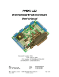
1
PMDX-105
I/O Option Riser Board
User’s Manual
Document Revision: 1.1
Date: 7 September 2004
PCB Revision: PCB-443A
PMDX
7432 Alban Station Blvd., A105
Springfield, VA 22150-2321 USA
PMDX-105_Manual_11.doc
7 September 2004
Web:
Phone:
FAX:
http://www.pmdx.com
+1 (703) 912-4991
+1 (703) 912-5849
©2004, Practical Micro Design, Inc.
All Rights Reserved
Page 1 of 9
PMDX-105 User’s Manual
PCB Revision: PCB-443A
Document Revision: 1.1
Table of Contents
1.0
Overview ....................................................................................................................................3
1.1
Configuration Options ....................................................................................................................................... 3
1.2
Important Safety Information ........................................................................................................................... 3
1.3
Warranty Summary............................................................................................................................................. 3
1.4
Features.................................................................................................................................................................. 4
1.5
Updates to this Manual....................................................................................................................................... 4
2.0
Connectors.................................................................................................................................4
2.1
Motherboard Connector (J1)........................................................................................................................... 4
2.2
Control Output Connector (J2)...................................................................................................................... 4
2.3
Status Input Connector (J3).............................................................................................................................. 5
2.4
Relay Contact Connectors (J7)........................................................................................................................ 6
3.0
Solid State Relays......................................................................................................................6
3.1
10-Amp Relay (optional).................................................................................................................................... 6
3.2
2-Amp Relay (optional) ...................................................................................................................................... 7
3.3
Relay Enable Jumper (JP1).................................................................................................................................. 7
4.0
Mechanical Specifications ........................................................................................................8
5.0
Electrical and Environmental Specifications.........................................................................8
Appendix A – Warranty ......................................................................................................................9
PMDX-105_Manual_11.doc
7 September 2004
©2004, Practical Micro Design, Inc.
All Rights Reserved
Page 2 of 9
PMDX-105 User’s Manual
PCB Revision: PCB-443A
Document Revision: 1.1
1.0
Overview
This document describes the configuration and operation of the PMDX-105 I/O Option Riser Board. The
PMDX-105 provides access to the PC parallel port status and control signals when used in conjunction
with the PMDX-130 4-Axis Motion Control Motherboard. This document pertains to the following
versions of the PMDX-105:
Circuit Board Revision:
1.1
PCB-443A (marked on the bottom of the board)
Configuration Options
The PMDX-105 can be built in several different configurations:
PMDX Part Number
PMDX-105-00
PMDX-105-01
PMDX-105-02
PMDX-105-03
Configuration
Basic I/O board, no solid-state relays
Basic I/O board with 2-Amp solid-state relay
Basic I/O board with 10-Amp solid-state relay
Basic I/O board with both 2-Amp and 10-Amp solid-state relays
Table 1 - PMDX-105 Configurations
1.2
Important Safety Information
The PMDX-105 is intended for integration by the purchaser into industrial control systems. It is solely
the purchaser's responsibility to assure that the system is configured in a manner consistent with
applicable safety requirements. Practical Micro Design, Inc. does not control how this board is integrated
into the purchaser's system and cannot be responsible for guaranteeing the safety of your system.
The PMDX-105 is not guaranteed to be fail-safe. The system into which the PMDX-105 is installed should
provide fail-safe protection and emergency stop capability.
The PMDX-105 contains circuitry that may be connected to dangerous voltages. Care must be taken that
user cannot come in contact with these voltages. An enclosure that allows for modest ventilation, but
prevents intrusion by operator’s hands and foreign objects, especially conductive byproducts of machining
operations, should be utilized with this board. Interlock switches on power circuits should remove
power when the enclosure is opened.
Automated machine tools, into which the PMDX-105 may be integrated, can cause injury. Precautions
should be taken to assure that operators are trained in their proper operation and safety procedures, and
that they are protected from moving parts that may be under remote control and may move
unexpectedly.
This product may not be used in life support or other critical safety applications.
1.3
Warranty Summary
The PMDX-105 is warranted against failure due to defective parts or workmanship for 90 days from the
date of sale. Refer to Appendix A for complete warranty details.
If you have an item requiring service, please see the support page on the PMDX web site
(http://www.pmdx.com) for return instructions.
The purchaser must pay shipping to return the unit to PMDX. We will ship the repaired unit back to you
via ground transportation at our expense. Repairs are normally completed within 10 business days. See
Appendix A for our complete warranty details.
PMDX-105_Manual_11.doc
7 September 2004
©2004, Practical Micro Design, Inc.
All Rights Reserved
Page 3 of 9
PMDX-105 User’s Manual
PCB Revision: PCB-443A
Document Revision: 1.1
1.4
Features
The PMDX-105 has the following features:
Status Inputs:
• 4 each general-purpose digital inputs
•
E-Stop input
•
Wire clamp screw terminals for each input
Control Outputs:
• 4 each general purpose digital outputs
•
“Charge Pump OK” output
•
Wire clamp screw terminals for all outputs
1.5
Solid-State Relay Outputs (optional):
• Optional 10-Amp opto-isolated 240 VAC
relay output
•
Optional 2-Amp opto-isolated 240 VAC
relay output
•
Wire clamp screw terminals
•
“Charge Pump OK” override via jumper
option
Updates to this Manual
Check the PMDX web site for revisions or updates to this manual (http://www.pmdx.com). The latest
revision of this manual is available on the PMDX-105 page (follow the links from the main page).
2.0
Connectors
The PMDX-105 contains the following connectors. Refer to the following sections for details on the pinouts for each connector. For all connectors, pin “1” is the pin closest to the reference designator (i.e. J1
pin 1 is the pin closest to the “J1” text on the circuit board). In addition, all connectors have square pads
on pin 1 (look on the bottom of the circuit board).
Connector
J1
J2
J3
J7
Description
Motherboard Connector (mates with PMDX-130 Motherboard)
Control Outputs
Status Inputs
Solid-State Relay Outputs
Table 2 - Summary of PMDX-105 Connectors
2.1
Motherboard Connector (J1)
This connector plugs into the “P2” connector on the PMDX-130 motherboard (which is labeled “I/O
Card Slot”). The PMDX-105 should be plugged in so that the screw terminal connectors are towards the
edge of the PMDX-130 that has the Centronics (parallel port) connector.
WARNING:
2.2
Use caution when installing this board onto the PMDX-130 motherboard. It is
possible to plug the board into the motherboard connector such that the
connectors are not properly aligned.
Control Output Connector (J2)
The PMDX-105 brings all four PC parallel port control signals to the J2 connector. These signals connect
directly to the corresponding PC parallel port control signals (by way of the PMDX-130 motherboard).
They are not buffered, nor are they opto-isolated.
The “Charge Pump OK” signal from the PMDX-130 motherboard is also present on this connector.
PMDX-105_Manual_11.doc
7 September 2004
©2004, Practical Micro Design, Inc.
All Rights Reserved
Page 4 of 9
PMDX-105 User’s Manual
PCB Revision: PCB-443A
Document Revision: 1.1
The “~” character before the signal name indicates that the normal PC parallel port function uses that
signal as an “active low” output. The actual polarity for motion control purposes depends on the
application software that you are using.
Pin
Number
1
Parallel
Port Pin #
N/A
N/A
2
3
4
5
6
1
14
16
17
Description
Ground
~CP_OK (the “Charge Pump OK” signal from the PMDX-130 motherboard).
This signal is intended to be the “ground” reference for any opto-isolators
used with the PMDX-105, so that the opto-isolators can be disabled when the
PMDX-130’s charge pump detects a problem. This signal is either “ground”
or “open circuit”.
~Strobe (also controls one of the optional solid-state relays, see section 3.1)
AutoFeed (also controls one of the optional solid-state relays, see section
3.2)
~Init
~Select_In
Table 3 – Control Output Connector Pin-Out (J2)
WARNING:
Do not use “~Strobe” and “AutoFeed” as general-purpose outputs on this
connector when using the corresponding on-board solid-state relays.
NOTE – Due to logic inside the PC, some control outputs are inverted. This means that that
writing a “1” to a bit in the control register may result in a logic “low” at the 25-pin D
connector. Please refer to technical documentation on the PC parallel port, or your
control software, for more information.
2.3
Status Input Connector (J3)
The PMDX-105 provides screw terminals for four of the five PC parallel port status signals. These signals
connect directly to the corresponding PC parallel port signals (by way of the PMDX-130 motherboard).
They are not buffered, nor are they opto-isolated. The “~Ack” status signal is not brought out on the
PMDX-105 board because the PMDX-130 motherboard uses this signal to send it’s fault status to the PC.
This connector also provides access for an external “Emergency Stop” (“E-Stop”) input. The E-Stop input
should be connected to an external “normally closed” switch (or group of switches all wired in series).
The external switch(es) should be wired between the E-Stop pin and ground, such that the switch
contacts open to indicate an emergency stop condition. Refer to the PMDX-130 User’s Manual for more
information on the emergency stop function. If no E-Stop circuit is provided, a jumper wire must be
installed between the E-Stop pin and ground.
The “~” character before the signal name indicates that the normal PC parallel port function uses that
signal as an “active low” input. The actual polarity for motion control purposes depends on the
application software that you are using.
PMDX-105_Manual_11.doc
7 September 2004
©2004, Practical Micro Design, Inc.
All Rights Reserved
Page 5 of 9
PMDX-105 User’s Manual
PCB Revision: PCB-443A
Document Revision: 1.1
Pin
Number
1
2
3
4
5
6
Parallel
Port Pin #
N/A
N/A
11
12
13
15
Description
Ground
E-Stop Input
Busy
PE (Paper Empty)
Select Out
~Error
Table 4 – Status Input Connector Pin-Out (J3)
NOTE – Due to logic inside the PC, some status inputs are inverted. This means that for
some status signals, a logic “high” input from the PMDX-105 to the PC’s parallel port
is read as a “0” in the status register. Please refer to technical documentation on the
PC parallel port, or your control software, for more information.
2.4
Relay Contact Connector (J7)
The relay contact connector is populated if the PMDX-105 has one or both of the optional solid-state AC
relays. See section 3.0 for more information on these optional relays.
Pin Number
1
2
3
Description
Relay common input (AC voltage source)
10-Amp switched load (requires external fuse, see section 3.1)
2-Amp switched load (see section 3.2)
Table 5 – Relay Contact Output Connector Pin-Out (J7)
3.0
Solid State Relays
The PMDX-105 has provisions for two optional solid-state AC relays. These relays allow the PC to
control AC power to external devices such as spindle motors and coolant pumps. The relays are
controlled by two of the PC’s parallel port control signals. Jumper JP1 determines if the “Charge Pump
OK” signal can force the relays to the “open” state (see section 3.3).
3.1
10-Amp Relay (optional)
Relay “K1” (if installed) is a 10-Amp, 240 VAC solid-state relay. This relay requires the use of an external
10-Amp (maximum) fuse in the “Relay Common Input” lead (see section 2.4).
The relay is controlled by the PC parallel port “~Strobe” signal (PC parallel port connector pin 1). The
relay is “open” when the ~Strobe signal is a logic low, and “closed” when the ~Strobe signal is a logic high.
The “Charge Pump OK” signal may override this control and force the relay to the “open” state,
depending on the setting of JP1 (see section 3.3).
WARNING:
Do not use the “~Strobe” signal on the Control Output Connector (J2) when
using this on-board solid-state relay.
PMDX-105_Manual_11.doc
7 September 2004
©2004, Practical Micro Design, Inc.
All Rights Reserved
Page 6 of 9
PMDX-105 User’s Manual
PCB Revision: PCB-443A
Document Revision: 1.1
NOTE – Due to logic inside the PC, the “~Stobe” control output is inverted. This means that
writing a “1” to a bit in the control register results in a logic “low” at the PC’s 25-pin
“D” connector. In order to energize (“close”) the relay, a “0” must be written to the
parallel port control register. Please refer to technical documentation on the PC
parallel port, or your control software, for more information.
3.2
2-Amp Relay (optional)
Relay “K2” (if installed) is a 2-Amp, 240 VAC solid-state relay. The PMDX-105 provides an on-board
2-Amp fuse for this relay. This fuse is a 5mm x 20mm fuse, and must be no greater than 2 amps.
The 2-Amp relay is controlled by the PC parallel port “AutoFeed” signal (PC parallel port connector pin
14). The relay is “open” when the AutoFeed signal is a logic low, and “closed” when the AutoFeed signal
is a logic high. The “Charge Pump OK” signal may override this control and force the relay to the “open”
state, depending on the setting of JP1 (see section 3.3).
WARNING:
3.3
Do not use the “AutoFeed” signal on the Control Output Connector (J2) when
using this on-board solid-state relay.
Relay Enable Jumper (JP1)
Jumper JP1 is labeled “RelayEN” and selects whether or not the PMDX-130’s charge pump circuit can
disable the solid-state relays.
Setting
Label
Description
PMDX-130’s “Charge Pump OK” signal determines relay state as follows:
Charge pump is OK:
1 to 2
CP-OK
PC parallel port signals determine whether the
relays are “open” or “closed”
Charge pump is NOT OK: relays are forced to the “open” state, ignoring the
PC parallel control signals
2 to 3
always
Relays always respond to the PC parallel port control signals
Table 6 –Relay Enable Jumper Settings (JP1)
PMDX-105_Manual_11.doc
7 September 2004
©2004, Practical Micro Design, Inc.
All Rights Reserved
Page 7 of 9
PMDX-105 User’s Manual
PCB Revision: PCB-443A
Document Revision: 1.1
4.0
Mechanical Specifications
2.750"
6
5
4
3
J3
Inputs
3.400"
2
1
6
5
4
3
2
J1
1
J2
Outputs
Figure 1 - PMDX-105 Dimensions and Mounting Holes
WARNING: The PMDX-105 should be protected from liquids, dirt, or chips
(especially metal chips which can cause shorts) coming in contact with
the board.
5.0
Electrical and Environmental Specifications
Status Inputs:
Refer to the PMDX-130 User’s Manual for status input signal levels
Control Outputs:
Refer to the PMDX-130 User’s Manual for control output signal levels
Solid-State Relays:
Relay “K1”
Relay “K2”
Environmental:
240 VAC maximum, 10 amps maximum, from relay common terminal
(requires an external fuse)
240 VAC maximum, 2 amps maximum, from relay common terminal
(has on-board fuse)
Temperature:
Relative Humidity:
PMDX-105_Manual_11.doc
7 September 2004
0° to +55° C
20% to 80% relative humidity, non-condensing
©2004, Practical Micro Design, Inc.
All Rights Reserved
Page 8 of 9
PMDX-105 User’s Manual
PCB Revision: PCB-443A
Document Revision: 1.1
Appendix A – Warranty
Statement
Practical Micro Design, Inc. (PMD) warrants that this hardware product is in good working
condition, according to its specifications at the time of shipment, for a period of 90 days
from the date it was shipped from PMD. Should the product, in PMD's opinion, malfunction
within the warranty period, PMD will repair or replace the product without charge. Any
replaced parts become the property of PMD. This warranty does not apply to the software
component of a product or to a product which has been damaged due to accident, misuse,
abuse, improper installation, usage not in accordance with product specifications and
instructions, natural or personal disaster or unauthorized alterations, repairs or
modifications.
Limitations
All warranties for this product, expressed or implied, are limited to 90 days from the date of
purchase and no warranties, expressed or implied, will apply after that period.
All warranties for this product, expressed or implied, shall extend only to the original
purchaser.
The liability of Practical Micro Design, Inc. in respect of any defective product will be limited
to the repair or replacement of such product. Practical Micro Design, Inc. may use new or
equivalent to new replacement parts.
Practical Micro Design, Inc. makes no other representations or warranties as to fitness for
purpose, merchantability or otherwise in respect of the product. No other representations,
warranties or conditions, shall be implied by statute or otherwise.
In no event shall Practical Micro Design, Inc. be responsible or liable for any damages arising
(a) from the use of the product;
(b) from the loss of use of the product;
(c) from the loss of revenue or profit resulting from the use of the product; or
(d) as a result of any event, circumstance, action or abuse beyond the control of Practical
Micro Design, Inc.
whether such damages be direct, indirect, consequential, special or otherwise and whether
such damages are incurred by the person to whom this warranty extends or a third party.
PMDX-105_Manual_11.doc
7 September 2004
©2004, Practical Micro Design, Inc.
All Rights Reserved
Page 9 of 9