1
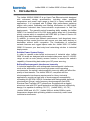
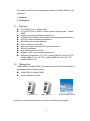
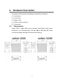
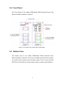
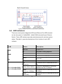
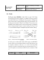
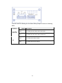
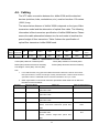
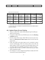
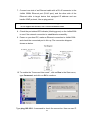
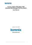
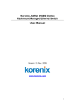
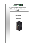
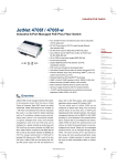
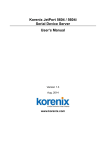
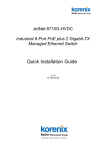
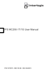
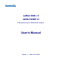
JetNet 3008 v3 JetNet 3008f v3 Industrial 8-port Ethernet Switch User’s Manual Version:1.1 Date: 26-Jun-2013 Content 1. Introduction ................................................................. 1 1-1. Features ...................................................................... 2 1-2. Packing List ................................................................. 2 2. Hardware Description .................................................. 3 2.1. Dimensions ........................................................... 3 2-2 Front Panel ........................................................... 4 2-3. Bottom View .......................................................... 4 2-4. LED Indicators ...................................................... 5 2-5. Ports ..................................................................... 6 3. Mounting Installation ................................................... 7 DIN-Rail Mounting ............................................................... 7 4. Hardware Installation .................................................. 9 4-1. Wiring the DC Power Inputs ................................ 10 4-2. Wiring the Alarm Relay ....................................... 11 4-3. Wiring Earth Grounding ....................................... 12 4-4. Enabled the Event Alarm Function ...................... 12 4-5. Cabling ................................................................ 14 4-6. System Power-On and Testing ........................... 15 5. Packet forwarding and filtering ability ........................ 19 5-1. Broadcast Control ............................................... 19 5-2. Quality of Service ................................................ 19 6. Trouble shooting ....................................................... 22 Federal Communications Commission (FCC) Statement This equipment has been tested and found to comply with the limits for a Class A digital device, pursuant to Part 15 of the FCC Rules. These limits are designed to provide reasonable protection against harmful interference when the equipment is operated in a commercial environment. This equipment generates, uses, and can radiate radio frequency energy and, if not installed and used in accordance with the instruction manual, may cause harmful interference to radio communications. Operation of this equipment in a residential area is likely to cause harmful interference in which case the user will be required to correct the interference at his expense. The user is cautioned that changes and modifications made to the equipment without approval of the manufacturer could void the user's authority to operate this equipment . JetNet 3008 v3 / JetNet 3008f v3 User’s Manual 1. Introduction The JetNet 3008V3/ 3008f V3 is an 8-port Fast Ethernet switch designed with enhanced design specifications, including wider operating temperature and power input range to best fit in heavy industrial field applications. It is equipped with 2.0Gbps High performance switching engine with packet forwarding and filtering mechanism to fulfill higher performance industrial data communication requirements in field site deployments. The graceful packet forwarding ability enables the JetNet 3008f V3 to handle from 64 to 1522 bytes packet sizes into 2 forwarding priority queues which is compliant with IEEE 802.1p Class of Service for providing best data forwarding performance. In addition, to ensure best network performance, both broadcast storm filtering and flow control functions can ensure your data traffic delivery to destination without traffic congestion. The combination of enhanced network features and rugged specs make the JetNet 3008 V3 /JetNet 3008f V3 become your best entry-level networking solution in industrial deployments. Reliable Power System Design In order to operate under harsh environment of industrial sites, JetNet 3008 V3 series are designed with redundant wide power input 10~60VDC range as well as auto polarity reverse function to ensure the switch’s capability of transmitting data under poor DC power sourcing. Brilliant Electromagnetic Interference Immunity In industrial applications with widespread electromagnetic interference, such as the automation control and high power motor operating environments, the switch’s electromagnetic immunity ability will affect the quality of data transfer. The JetNet 3008 V3, compliant with the electromagnetic interference requirements for Heavy Industrial applications, provides a high level of electromagnetic susceptibility exceeding the IEC/EN 61000-6-2 standard with distinguished electrical slow transient (Surge), radio-frequency electromagnetic field (RS), Electrical Fast Transient (EFT) protections. Equipped with a rugged aluminum case with IP31 grade protection and high thermal conductivity design, it is capable of resisting -25~70℃ (JetNet 3008), -10~70℃ (JetNet 3008f) and -40~75℃(JetNet 3008-w/ JetNet 3008f-w) wide temperature ranges while providing reliable connectivity under harsh industrial environments. 1 This session will introduce following information of JetNet 3008 for your reference. 1. Features 2. Packing list 1-1. Features 8 10/100TX ports – JetNet 3008 6 10/100TX, plus 2 100FX in Multi-mode or Single-mode – JetNet 3008f Compact size with full power redundancy 2.0Gbps Switch Fabric with excellent data exchange performance QoS for packet forwarding precedence Broadcast storm packet filtering Port and power event alarm Aluminum metal case with IP31 grade protection DIN rail installation Dual power input DC10~60V Support 1.5KV Hi-Pot isolation protection Operating temperature: -25~70oC (JetNet 3008 V3) and -40~75oC (JetNet 3008-w V3), -10~70oC (JetNet 3008f V3) and -40~75oC (JetNet 3008f-w V3) 1-2. Packing List JetNet 3008 v3/JetNet 3008f v3 Industrial 8-port Fast Ethernet Switch is packaged with the following items: JetNet 3008 or JetNet 3008f Quick Installation Guide JetNet3008 v3 JetNet 3008f v3 Quick Installation Guide Contact your sales representative if any item is missing or damaged. 2 2. Hardware Description This session will introduce the hardware information as following: 2-1. dimensions 2-2. Front Panel 2-3. Bottom View 2-4. LEDs of system and port 2-5. Connectors 2.1. Dimensions JetNet 3008 / JetNet 3008f 8-port Industrial Fast Ethernet Rail Switch dimensions are 120 mm (H) x 55 mm (W) x 108 mm (D), detail mechanical design drawings are attached as following: 3 2-2 Front Panel The Front Panel of the JetNet 3008/JetNet 3008f Industrial 8-port Fast Ethernet Switch is shown in Figure A. Figure A. Front Panel of the JetNet 3008 / JetNet 3008f. 2-3. Bottom View The bottom view of the JetNet 3008/JetNet 3008f Industrial 8-port Ethernet Switch consists of one 6-pin removable terminal block connector for two DC power inputs and event alarm output. There is one 9-pin DIP SWITCH on the bottom for alarm control of port or power event selection. 4 Figure B. Bottom view of the JetNet 3008/ JetNet 3008f 2-4. LED Indicators There are some system diagnostic LEDs and Ethernet Port LEDs located on the front panel of JetNet3008 / JetNet 3008f Industrial 8-port Ethernet Switch. These LED indicators provide administrators with real-time system status. The table-1 gives the descriptions of the function of each LED indicator. LED PWR1 PWR2 Alm Port 1~8 (JetNet 3008) Port 1~6 (JetNet 3008f) Status Description Green on Power is on. Off No power is being supplied. Green on Power is on. Off No power is being supplied. Red on Port link down or power failure event occurred. Off No event. Link (Green on ) A network device is detected and link up. Activity (Green blinks) The port is transmitting or receiving packets from the TX device. Speed (Yellow on/ 100Mbps) A network device is detected and link on 100Mbps. Speed (Yellow off) A network device is detected and link on 10Mbps. 5 Fiber port #7, #8 (JetNet 3008f) 100Mbps Link (Green on) The port is operating in full-duplex mode. 100Mbps Activity (Green Blinks) The port is transmitting or receiving packets from the TX device. Table 1 2-5. Ports RJ-45 ports (Auto MDI/MDIX): JetNet 3008 has eight 10/100 Mbps auto-sensing RJ-45 ports for 10Base-T or 100Base-TX device connection and JetNet 3008f has six 10/100Mbps RJ-45 ports and two 100Mbps fiber ports for multi-mode or single-mode fiber cable in SC type connector. The RJ-45 ports will auto-detect 10Base-T and 100Base-TX connections. Auto MDI/MDIX function allows users to connect another switch or workstation without changing straight through or crossover cabling. See Figure C and C-1 for the schematic diagram of straight through and crossover cabling. Figure C Straight Through Cabling Schematic Schematic Figure C-1 Cross Over Cabling All RJ-45 ports of JetNet 3008/ JetNet 3008f support auto-MDI/MDI-X function. When you use an Ethernet cable to connect other devices, such as computers, switches or hubs, pin 1, 2, 3, and 6 of the 8-pin RJ45 connector are used to communicate with the connected devices. Pin1, 2, 3, and 6’s signals are converted by the MDI-X function, as shown in Table -2. Pin MDI-X Signals MDI Signals 6 1 RD+ TD+ 2 RD- TD- 3 TD+ RD+ 6 TD- RD- Table-2 3. Mounting Installation DIN-Rail Mounting The DIN-Rail clip is already attached on the rear side of JetNet 3008/ JetNet 3008f. JetNet 3008 series supports EN 50022 standard DIN Rail, in the following diagram includes the dimension of EN 55022 DIN Rail for your reference. The DIN rail should behind the spring when install the JetNet 3008/JetNet 3008f onto the standard DIN Rail. Follow the steps below to mount the JetNet 3008 /JetNet 3008f on the DIN-Rail track. 1. Insert the upper end of the DIN-Rail clip into the back of the DIN-Rail track from its upper side 2. Lightly push the bottom of the DIN-Rail clip into the track. 3. Check if the DIN-Rail clip is 7 tightly attached to the track. 4. To remove the JetNet 3008/ JetNet 3008f-m from the track, reverse the steps above. 8 4. Hardware Installation The following figure illustrates a typical application of JetNet 3008 / JetNet 3008f in field site. It includes Enterprise communication backbone network, Factory communication, field site communication and field site control layers. The control equipments access and report production information through the JetNet 3008 or JetNet 3008f and uplink to factory communication level by fiber or copper which with network redundancy. This session will introduce the hardware installation, includes: 4-1. Wiring the DC Power Inputs 4-2. Wiring the Relay Alarm 4-3. Wiring Earth Grounding 4-4 Enable Alarm Relay Function 4-5. Cabling 4-6. System Power-On and Testing 9 4-1. Wiring the DC Power Inputs Follow the steps below to wire JetNet 3008’s / JetNet 3008f’s dual DC power inputs. [Note] The suitable electric wire ranges is from 12 to 24 AWG. V- V+ V- V+ 1. Insert the positive and negative wires into the V+ and Vcontacts respectively of the terminal block connector 2. Tighten the wire-clamp screws to prevent the DC wires from being loosened. Equipment intended for installation in a Restricted Access Location. Before install power, be sure the power supply module is compliance with UL certificated LPS power and the power system is shut down to avoid any damage. About the wiring please refer following diagram. 10 4-2. Wiring the Alarm Relay JetNet 3008 /JetNet 3008f provides one dry relay output for power or port link event; the alarm relay is “Normal open” and form a close circuit when The relay conductor ability is 12W when it connects with a DC 24V power source and maximum current is 0.5A. In the following diagram shows how to make an alarm circuit. Maximum 0.5A current / DC24V 11 4-3. Wiring Earth Grounding In the real fields, there might have a lot of automatic device, such as AC motors, electric welding machine, power generator; those devices will generate electromagnetic and disturb communications. To prevent those noises, the switch should be well earthed. In the figure-shows how to make connection. 4-4. Enabled the Event Alarm Function This session introduces how to configure and enable the event alarm to alert maintenance engineer once system event occurred. Both of JetNet 3008 and JetNet 3008f equipped with one dry relay output for port link fails or power fails. The feature is controlled by digital control circuits and effect immediately without system reset when DIP SWITCH changed. On the bottom side of JetNet 3008 and JetNet 3008f, there is one 9-Pin DIP SWITCH for alarm control. By inserting the port and power wiring, setting the DIP SWITCH of the intended Alarm to “ON”, the relay output will form a short circuit if alarm occurred. 12 The DIP SWITCH Setting for the Alarm Relay Output is show as following table. Pin No. # P1 to P8 (Pin1 ~8) Status Description ON To enable port link down alarm at this port. Off To disable port link down alarm at this port. ON To enable power failure alarm. Off To disable power failure alarm. P9 13 4-5. Cabling The UTP cable connection between the JetNet 3008 and the attached devices (switches, hubs, workstations, etc.) must be less than 100 meters (328 ft.) long. The transmission distance of JetNet 3008f is depends on the type of fiber transceiver model and the attenuation of optical fiber cable. The following information is fiber transceiver specification of JetNet 3008f series. Please ensure the cable attenuation between two far end nodes is less than the power budget of fiber transceiver. Table-3 shows the specification of optical fiber transceiver JetNet 3008f used. Con. Wavelength TXPwr(min) TxPwr(Max) RxPwr(Min) RxPwr(Max) JetNet Multi-mode 3008f-m 50~62.5/125 model Cable Type SC 1310nm -20dBm -14dBm -31dBm 0dBm 11dBm JetNet 3008f-s SC 1310nm -15dBm -8dBm -34dBm -8dBm 19dBm Single-mode 8~10/125 Table -3 LinkBudg(dbm) Distance(km) 2Km/5Km Note1 30km Specification of Fiber Transceiver TxPwr (Min): Minimum Transmit power TxPwr (Max): Maximum Transmit power RxPwr (Min): Maximum Receive sensitivity RxPwr (Max): Minimum Receive sensitivity Link Budget= TxPwr (Min) –Rx Pwr (Min) Note: 1. In the IEEE standard, it suggests the available transmission distance is 2KM for 62.5/125um fiber optical cable in 1310nm wave length. Actually, the attenuation of multi-mode 62.5/125um optical fiber cable is 1.5dBm/KM and the maximum link distance can up to 4~5km. 2. IEEE organization recommends maximum optical fiber cable distances as defined in the table-4 shows as below: Standard 10Base-FL Data Rate (Mbps) Cable type IEEE standard Distance 10 850nm, 50/125um or 62.5/125um Multi-mode 2km optical fiber cable 100Base-FX 100 1310nm,50/125um or 62.5/125um Multi-mode 2km optical fiber cable 100Base-SX 100 850nm, 50/125um or 62.5/125um Multi-mode 300m optical fiber cable 1000Base-SX 1000 850nm, 50/125um Multi-mode optical fiber cable 550m 850nm, 62.5/125um Multi-mode optical fiber 220m cable 1000Base-LX 1000 1310nm, 50/125um or 62.5/125um Multi-mode optical fiber cable 550m 5km 1310nm, 9/125um Single-mode optical fiber cable 14 1000Base-LH 1000 1550nm,9/125um Single-mode optical fiber cable 70km Optical Fiber cable attenuation Fiber Type Wave length Multi mode 850nm 3.5dBm 2.5dBm 50/125um 1310mm 1.5dBm 0.8dBm Multi mode 850nm 3.5dBm 3.0dBm 62.5/125um 1310nm 1.5dBm 0.7dBm 1310nm 0.4dBm 1550nm 0.3dBm Single mode 9/125um Single mode 9/125um Attenuation /km *1 Attenuation /km *2 Connector loss Splice loss 0.75dBm 0.1dBm 0.75dBm 0.1dBm 0.35dBm 0.75dBm 0.1dBm 0.22dBm 0.75dBm 0.1dBm Table-4 * 1. These values are per TIA/EIA and other industrial specifications. * 2. These values are one example of the performance that can be obtained with a new fiber installation. 4-6. System Power-On and Testing 1. Take your JetNet 3008 / JetNet 3008f Industrial 8-port Fast Ethernet Switch out from the box. 2. To place the JetNet 3008 on the DIN-Rail track, refer to the Mounting Installation section. 3. Pull the terminal block off the JetNet 3008 and wire the power lines. Refer to the Wiring the DC Power Inputs section for how to wire the power inputs. 4. PWR1 and PWR2 dual power inputs can be connected to power sources simultaneously. When the primary power source fails (the default setting is PWR1), the system will automatically switch to the secondary power source (PWR2), preventing any power interruption. 5. Check the LEDs for PWR1 and PWR2 to make sure that your JetNet 3008 is operating normally. 6. Use Category-5 or above straight through Ethernet cables with RJ-45 connectors to connect network devices. 15 7. Connect one side of an Ethernet cable with a RJ-45 connector to the JetNet 3008’s Ethernet port (RJ-45 port), and the other side of the Ethernet cable to target device that equipped IP address and can handle ICMP protocol, like as ping packet. [Note] Make sure that the connected network switches support MDI/MDI-X function. If they do not support this function, use a crossover Ethernet cable. 8. Check the port status LED indicator (blinking green) on the JetNet3008 to see if the network connection is established successfully. 9. Power on your host PC, make an Ethernet connection to JetNet 3008 and check the connected port is link up ;The connection diagram shown as below: 10. To enable the “Command Line mode”, click on Run in the Start menu, type Command, and click on OK to continue. Type ping 192.168.1.1 command to check the connection. Here we use IP 16 address 192.168.1.1 as an example. 11. Repeat step 10 to make sure that the connection of each device connected to the JetNet3008 is successfully established. 12. Power on the PC host, activate the Command Line mode, and ping the connected Ethernet device by typing “ping 192.168.1.1 –t” command to see if it will respond. Do remember the PC host IP address is same subnet address as target device – 192.168.1.1. 13. The parameter-”t” allow you to continue to ping the network device, as shown in the figure below. Before you continue, make sure that both PWR1 and PWR2 are 17 successfully connected to power sources. When PWR1 fails, the LED for PWR1 will go out. At that moment, if the ping command is still being replied to, then it proves that the redundant power input function works normally. 18 5. Packet forwarding and filtering ability The JetNet 3008/ JetNet 3008f features packet filtering functions for broadcast packet control protection and QoS. Both of features can provide more graceful performance in a crowded network by traffic filtering and prioritize. This session will introduce the principle of traffic control and forwarding precedence, includes Broadcast control and Quality of Service. 5-1. Broadcast Control The JetNet 3008 or JetNet 3008f begins to drops broadcast packets which DA ( destination address) are equal to FF:FF:FF:FF:FF:FF if the received broadcast packets are more than the threshold – 198 packets/ per second at 100Mbps or 19 packets / per second at 10Mbps link speed. All of ports are enabled with this function without any configuration to provides better network performance and prevent network congest with the flooding of broadcast packets. 5-2. Quality of Service The JetNet 3008 / 3008f supports frame type priority function, high priority packet will be queued to high priority queue to share more bandwidth. The ratio of bandwidth of high priority and low priority queue is 8:1. After 8 high priority packets is progressed, then 1 low priority. Both of JetNet 3008 and JetNet 3008f can examine the specific bits of VLAN Tag and TCP/IP TOS of IPv4 and IPv6. IEEE 802.1Q tag based CoS The JetNet 3008/ 3008f will examine the 3 bits of priority field carried by a VLAN tag and map it to the corresponding priority. A packet with priority field ranging from 0 to 3 will be treated as a low priority packet, and will be stored in low priority queue. A packet with priority field ranging from 4 to 7 will be treated as a high priority packet, and will be stored in high priority queue. 19 IEEE 802.1Q Type of Service for IPv4 /IPv6 packet The JetNet 3008/3008f also provides the IP layer CoS (Class of Service) function by recognizing the priority octet and mapping it to the corresponding priority. For an IPv4 packet, it is embedded in the TOS (type of Service) Octet. For an IPv6 data packet, the Traffic Class Octet is used to differentiate the Class of Service. When this function is enabled, the JetNet 3008/ 3008f will automatically recognize the IP version and capture the either the TOS field (IPv4) or Traffic Class field (IPv6) and distributes the packet into High or Low Queue. 20 21 6. Trouble shooting Make sure you are using the correct DC power suppliers (DC12 to 48 V). Do not use power suppliers with DC output over 48V. It may damage devices. Select Ethernet cables with specifications suitable for your applications to set up your systems. Ethernet cables are categorized into unshielded twisted-pair (UTP) and shielded twisted-pair (STP) cables. Category 3, 4, 5, 6 Ethernet cables are suitable for systems with 10 Mbps transmission speed. For systems with 100 Mbps transmission speed, Category 5, 6 Ethernet cables are the only suitable specifications for this environment. You also need to make sure that the distance between each node cannot be longer than 100 meters (328 feet). If the power LEDs go off when the power cord is plugged in, a power failure might occur. Check the power output connection to see if there is any error at the power source. If you still cannot solve the problem, contact your local dealer for assistance. 22 7. Technical Specifications Technology Standard IEEE 802.3 10Base-T Ethernet IEEE 802.3u 100Base-TX /100Base-FX Fast Ethernet IEEE 802.3x Flow Control and Back-pressure IEEE 802.1p Class of Service (CoS) System Performance Switch Technology Store and Forward Technology with 2.0Gbps Switch Fabric System Throughput Mega packets per second, 64 bytes packet size 14,880pps for 10Base-T 148,800pps for 100Base-TX (pps: Packet Per Second) Transfer performance 14,880pps for Ethernet and 148,800 for Fast Ethernet Transfer packet size 64 bytes to 1522bytes (includes VLAN Tag) MAC Address 2K MAC address table with auto learning Packet Buffer 448Kilo bits shared memory for packet buffer Relay Alarm Output Dry Relay output with 0.5A /24V DC ability Broadcast Storm Control Default enabled. traffic threshold: 200 packets/ Sec. @100Mbps; 20 packets/Sec. @ 10Mbps Class of Service Provides 2 packet forwarding Queues: High Queue (4~7), Low Queue (0~3) Quality of Service Default Enabled. Supports VLAN tag priority and IPv4 packet precedence Event alarm relay Provides port and power event alarm; Enabled by 9-PIN Dipswitch Interface Enclosure Port Fast Ethernet communication port: 8 x RJ-45 Alarm relay & Power input: 6 pint removable terminal block Cables 10Base-T: 2-pairs UTP/STP Cat. 3, 4, 5 cable, EIA/TIA-568B 100-ohm (100m) 100 Base-TX: 2-pairs UTP/STP Cat. 5 cable, EIA/TIA-568B 100-ohm (100m) 100Base-FX: Multi-mode ( 50/125um, 62.5/125um) fiber cable /2KM , Single-mode (8/125um, 9/125um, 10/125um) fiber cable/ 30KM Fiber Transceiver JetNet 3008f-m V3 Wave-length:1310nm Tx Power: -14 ~-20dBm (Min.) Rx Sensitivity: 0~-31dBm (Max.) Link Budget: 11dB JetNet 3008f-s V3 Wave-length:1310nm Tx Power:-15~-8dBm (Min.) Rx Sensitivity:-34~-8dBm (Max.) Link Budget:19dB 23 System Diagnostic LEDs System Power status (Green): On ( power is on applying) Alarm Output (Red): On (Output conductor is formed as a close circuit) Ethernet port RJ-45: Link (Green on) / Activity (Green blinks) RJ-45: 100Mbps Link (Yellow on)/ 10Mbps Link (Yellow off) 100Mbps Fiber: Link( Green on)/ Active (Green blinks) Power Requirements System Power 2 x Redundant power input with polarity auto reverse function Power Input Range: DC 24V (Voltage fluctuations range: 10~60V Power System Type: Positive or Negative power source Power Consumption 3.0 Watts / DC 24V ; Inrush current:62.8A @ DC 60V Mechanical Installation DIN Rail Mounting Case Aluminum metal case with grade 31 protection Dimension (mm) 55(W) x 120(H) x 108 (D) / with DIN Rail Clip Weight JetNet 3008 V3: 0.555Kg JetNet 3008f V3:0.575kg Environmental Operating Temperature -25~70℃ ( JetNet 3008); -40~75 ℃ (JetNet 3008-w) Note-1 -10~70℃ ( JetNet 3008f); -40~75 ℃ (JetNet 3008f-w) Operating Humidity 0% ~ 90%, non-condensing Storage Temperature -40 ~ 85 ℃ Hi-Pot Insulation AC 1.5KV for Port-Port / Port-Case/Port-power , DC 1.5KV Power-Case Regulatory Approvals EMC Compliance with EN50121-4 Railway Track Side EMC EMI CISPR 16-1-2/ 16-2-1/ 16-2-3 / 22 FCC Part 15 Subpart B Class A, ANSI C63.4 Heavy Industrial IEC/EN61000-6-4 EMS Heavy Industrial IEC/EN 61000-6-2 IEC 61000-4-2, IEC 61000-4-3, IEC 61000-4-4, IEC 61000-4-5, IEC 61000-4-6, IEC 61000-4-8 Free Fall IEC60068-2-32 with package Warranty Global 5 years 24 Note-1 Revision History Edition Date Modifications V1.0 Nov-2011 Modify from 3008 V2 user manual. Relay 1A, 24V -> 0.5A, 24V ( Drawing) V1.1 26-Jun-2013 Remove – CD User Manual 25 About Korenix Less Time At Work! Fewer Budget on applications! The Korenix business idea is to let you spend less time at work and fewer budget on your applications. Do you really want to go through all the troubles but still end up with low quality products and lousy services? Definitely not! This is why you need Korenix. Korenix offers complete product selection that fulfills all your needs for applications. We provide easier, faster, tailor-made services, and more reliable solutions. In Korenix, there is no need to compromise. Korenix takes care of everything for you! Fusion of Outstandings You can end your searching here. Korenix Technology is your one-stop supply center for industrial communications and networking products. Korenix Technology is established by a group of professionals with more than 10 year experience in the arenas of industrial control, data communications and industrial networking applications. Korenix Technology is well-positioned to fulfill your needs and demands by providing a great variety of tailor-made products and services. Korenix’s industrial-grade products also come with quality services. No more searching, and no more worries. Korenix Technology stands by you all the way through. Core Strength---Competitive Price and Quality With our work experience and in-depth know-how of industrial communications and networking, Korenix Technology is able to combine Asia’s research / development ability with competitive production cost and with quality service and support. Global Sales Strategy Korenix’s global sales strategy focuses on establishing and developing trustworthy relationships with value added distributors and channel partners, and assisting OEM distributors to promote their own brands. Korenix supplies products to match local market requirements of design, quality, sales, marketing and customer services, allowing Korenix and distributors to create and enjoy profits together. Quality Services KoreCARE--- KoreCARE is Korenix Technology’s global service center, where our professional staffs are ready to solve your problems at any time and in real-time. All of Korenix’s products have passed ISO-9000/EMI/CE/FCC/UL certifications, fully satisfying your demands for product quality under critical industrial environments. Korenix global service center’s e-mail is [email protected] 5 Years Warranty Each of Korenix’s product line is designed, produced, and tested with high industrial standard. Korenix warrants that the Product(s) shall be free from defects in materials and workmanship for a period of five (5) years from the date of delivery provided that the Product was properly installed and used. This warranty is voided if defects, malfunctions or failures of the warranted Product are caused by damage resulting from force measure (such as floods, fire, etc.), environmental and atmospheric disturbances, other external forces such as power line disturbances, host computer malfunction, plugging the board in under power, or incorrect cabling; or the warranted Product is misused, abused, or operated, altered and repaired in an unauthorized or improper way 26