1
USER MANUAL
MB3 OPC Server v7.20-14
OPC Server for ABB MasterBus 300
By Novotek
Document version 7.20-14
This version printed: Friday 28 June 2013
Copyright 2013 Novotek Sverige AB
_________________________________________________________________________________________
User Manual
- 12013-06-28
MB3 OPC Server
OPC Server for ABB MasterBus 300
Program version 7.20-14
Copyright © 2013 Novotek Sverige AB
No part of the contents of this document may be reproduced, transmitted or translated to other
languages without permission from Novotek Sverige AB.
The information is subject to change without prior notice
All company names and other names, data and addresses that are shown in screen dumps and
other examples are fictive and have been worked out only to enhance understanding.
Novotek Sverige AB takes no responsibility for the function of the programs if:
Non recommended hardware and software are used
Any of the required programs has been shut off by any other that staff from Novotek Sverige AB
Virus has destroyed any files.
Version information
Revision
7.20-1
7.20-2
7.20-3
7.20-4
7.20-5
7.20-6
7.20-7
7.20-8
7.20-9
7.20-9c
7.20-9d
7.20-10
7.20-11
7.20-12
7.20-13
7.20-14
Date
2005-05-31
2005-11-02
2006-03-02
2006-07-12
2006-10-24
2007-04-25
2007-06-18
2007-10-24
2008-04-01
2011-07-08
2012-02-20
2012-02-24
2012-02-24
2012-11-02
2013-01-01
2013-06-27
Description
Created
Added TANKCON
Modified
Added A&E OPC functionality
Added TTD logs, DRICONS, DRICONE
Added MMI number functionality
Added Data Set
Modified
Added AC System Status objects
Added clock synch master
Added fast cyclic control
Added MultiDAT object
Merged versions for Win 7 and 2008 support
Added device control address “!PRI_STAT”
Added TTD subscription
Added redundant network support
_________________________________________________________________________________________
User Manual
- 22013-06-28
CONTENTS
1
1.1
1.2
2
2.1
2.2
3
3.1
3.2
4
4.1
4.2
5
5.1
5.2
5.3
5.4
6
6.1
6.2
6.3
6.4
6.5
6.6
6.7
7
7.1
7.2
7.3
7.4
7.5
7.6
7.7
8
8.1
8.2
8.3
9
ABOUT THE MB3 OPC SERVER .............................................................................................................. 6
REFERENCES ................................................................................................................................................. 6
ABBREVIATIONS ........................................................................................................................................... 6
GENERAL INFORMATION ....................................................................................................................... 7
WHAT IS MASTERBUS 300 ............................................................................................................................ 7
ABB COMMUNICATION ................................................................................................................................ 7
SUPPORTED HARDWARE ...................................................................................................................... 13
IN THE LOCAL COMPUTER .......................................................................................................................... 13
IN ABB ....................................................................................................................................................... 13
SOFTWARE ................................................................................................................................................. 14
SUPPORTED SOFTWARE............................................................................................................................... 14
REQUIRED SOFTWARE................................................................................................................................. 14
TESTED COMMUNICATION CONFIGURATIONS ............................................................................ 15
MB3 OPC SERVER ..................................................................................................................................... 15
ABB MASTER PIECE 280/1 ......................................................................................................................... 15
ABB ADVANT CONTROLLER 410................................................................................................................ 16
ABB ADVANT CONTROLLER 450................................................................................................................ 16
APPLICATION DESIGN CONSIDERATIONS USING OPC CLIENTS ............................................. 18
GENERAL .................................................................................................................................................... 18
DISPLAY ADDRESSING ................................................................................................................................ 18
ALARMS ...................................................................................................................................................... 18
CONTINUOUSLY UPDATE OF OBJECT .......................................................................................................... 19
SENDING ORDERS TO OBJECTS ................................................................................................................... 19
CONTINUOUSLY ORDER TO OBJECT ............................................................................................................ 19
BUILDING THE MB3 OPC SERVER CONFIGURATION .................................................................................. 19
APPLICATION DESIGN CONSIDERATIONS USING FIX ................................................................. 20
GENERAL .................................................................................................................................................... 20
DISPLAY ADDRESSING ................................................................................................................................ 20
ALARMS ...................................................................................................................................................... 20
CONTINUOUSLY UPDATE OF OBJECT .......................................................................................................... 21
SENDING ORDERS TO OBJECTS ................................................................................................................... 21
CONTINUOUSLY ORDER TO OBJECT ............................................................................................................ 21
BUILDING THE MB3 OPC SERVER CONFIGURATION .................................................................................. 21
INSTALLATION ......................................................................................................................................... 22
LICENSING SOFTWARE ................................................................................................................................ 22
MB3 OPC SERVER INSTALLATION ............................................................................................................. 23
MB3 OPC SERVER REGISTRATION ............................................................................................................. 26
SETTING UP THE ADAPTER IN THE LOCAL COMPUTER ............................................................ 29
9.1
9.2
NETWORK CONFIGURATION ........................................................................................................................ 29
ADAPTER MAC ADDRESS........................................................................................................................... 29
10
EVENT TREAT FILE AND UNACKNOWLEDGE OF OBJECT ALARMS .................................. 34
11
MB3 POWER TOOL ............................................................................................................................... 35
11.1 SETTING UP THE POWER TOOLS AND MB3 OPC SERVERS ENVIRONMENT ................................................. 40
11.2 CHANNEL CONFIGURATION ........................................................................................................................ 44
11.3 DEVICE CONFIGURATION ............................................................................................................................ 48
11.4 DATA BLOCK CONFIGURATION................................................................................................................... 50
11.5 CHANNEL, DEVICE AND DATA BLOCK TEMPLATES .................................................................................... 58
11.6 CSV FILE FORMAT ..................................................................................................................................... 58
_________________________________________________________________________________________
User Manual
- 32013-06-28
12
SYMBOLIC NAME TRANSLATION ................................................................................................... 62
12.1
12.2
12.3
NEW CONFIGURATION ................................................................................................................................ 62
FAILED NAME TRANSLATIONS .................................................................................................................... 62
ONLINE NAME TRANSLATIONS ................................................................................................................... 62
13
STARTUP OF THE MB3 OPC SERVER ............................................................................................. 63
14
ACCESSING THE MB3 OPC SERVER FROM OPC CLIENTS ...................................................... 65
14.1
14.2
14.3
14.4
14.5
ITEM ID FORMAT ........................................................................................................................................ 65
BROWSING THE MB3 OPC SERVER ............................................................................................................ 72
CLIENT REQUESTED DATA TYPE ................................................................................................................ 75
EXTRA ITEM ID INFORMATION ................................................................................................................... 76
ACCESSING THE MB3 OPC SERVER VIA DCOM ........................................................................................ 77
15
FIX DATABASE CONFIGURATION .................................................................................................. 80
15.1
15.2
15.3
15.4
15.5
DEVICE ....................................................................................................................................................... 80
HARDWARE OPTION.................................................................................................................................... 80
I/O ADDRESS FORMAT ................................................................................................................................ 81
SIGNAL CONDITIONING ............................................................................................................................... 87
OFFSET ADDRESSING WITH ANALOG AND DIGITAL REGISTER DATABASE BLOCKS.................................... 88
16
AUTO CONFIGURATION OF DATA BLOCKS FROM CLIENT APPLICATIONS .................... 91
17
RUNNING AS A SERVICE .................................................................................................................... 92
17.1
REGISTERING THE MB3 OPC SERVER AS A SERVICE .................................................................................. 92
18
COLLECTING TTD VARIABLE DATA ............................................................................................. 94
18.1
18.2
18.3
18.4
18.5
18.6
18.7
18.8
18.9
TTD ARCHIVING CONFIGURATION ............................................................................................................. 94
TTD OBJECT CONFIGURATION ................................................................................................................... 95
TTD LOG ITEM IDS .................................................................................................................................... 98
PROFICY HISTORIAN TAG CONFIGURATION .............................................................................................. 101
CSV FILE FORMAT ................................................................................................................................... 103
TIME SYNCHRONIZATION .......................................................................................................................... 103
SEAMLESS INTEGRATION WITH NOVOTEKTRENDVIEW COMPONENT ........................................................ 105
ABB TTD FUNCTIONALITY ...................................................................................................................... 107
TTD DEBUG ............................................................................................................................................. 108
19
TROUBLESHOOTING ........................................................................................................................ 112
19.1
19.2
19.3
19.4
19.5
19.6
19.7
PROBLEMS STARTING THE MB3 OPC SERVER.......................................................................................... 112
COMMUNICATION STATISTICS .................................................................................................................. 112
MB3 POWER TOOL TREE BROWSER ......................................................................................................... 118
DATA BLOCK DATA MONITOR IN POWER TOOL ....................................................................................... 120
MB3 OPC SERVER WINDOW .................................................................................................................... 121
EVENT VIEWER ......................................................................................................................................... 123
DATASCOPE .............................................................................................................................................. 123
20
QCS PROFILES AND THE MULTIDAT IMPLEMENTATION. ................................................... 125
21
APPENDIX A, OBJECT TYPE MAPS ............................................................................................... 126
21.1
21.2
21.3
21.4
21.5
21.6
21.7
21.8
21.9
21.10
AI OBJECT ................................................................................................................................................ 126
AO OBJECT ............................................................................................................................................... 127
DI OBJECT ................................................................................................................................................ 127
DO OBJECT ............................................................................................................................................... 128
DAT OBJECT ............................................................................................................................................ 129
MDAT OBJECT ......................................................................................................................................... 130
PIDCON OBJECT...................................................................................................................................... 130
PIDCONA OBJECT ................................................................................................................................... 133
RATIOSTN OBJECT ................................................................................................................................. 137
MANSTN OBJECT ................................................................................................................................ 139
_________________________________________________________________________________________
User Manual
- 42013-06-28
21.11
21.12
21.13
21.14
21.15
21.16
21.17
21.18
21.19
21.20
21.21
MMCX OBJECT .................................................................................................................................... 141
VALVECON OBJECT ........................................................................................................................... 144
MOTCON OBJECT ............................................................................................................................... 145
TEXT OBJECT ...................................................................................................................................... 147
GENUSD OBJECT ................................................................................................................................ 147
GENCON OBJECT ................................................................................................................................ 149
GENBIN OBJECT.................................................................................................................................. 151
SEQ OBJECT ......................................................................................................................................... 153
TANKCON OBJECT ............................................................................................................................. 156
DRICONS OBJECT ............................................................................................................................... 158
DRICONE OBJECT ............................................................................................................................... 163
22
APPENDIX B, SYSTEM STATUS OBJECTS.................................................................................... 169
22.1
22.2
22.3
22.4
22.5
22.6
22.7
22.8
22.9
22.10
AC OVERVIEW OBJECT ......................................................................................................................... 169
AC NODE OBJECT ................................................................................................................................... 169
NET OBJECT ............................................................................................................................................. 173
AC FIELDBUS_X OBJECT ....................................................................................................................... 173
AC SEL_FIELDBUS_X_Y OBJECT.......................................................................................................... 174
AC MASTER_FIELDBUS_X OBJECT ..................................................................................................... 177
AC S100_IO OBJECT ................................................................................................................................ 178
AC S100_IO2 OBJECT .............................................................................................................................. 179
AC S100_RED OBJECT ............................................................................................................................ 179
AC S100_EXT OBJECT ........................................................................................................................ 180
23
APPENDIX C, MB3NLS.INI FILE FORMAT ................................................................................... 181
24
APPENDIX D, PROCESS EVENT REASONS AND CODES .......................................................... 182
_________________________________________________________________________________________
User Manual
- 52013-06-28
1 About the MB3 OPC Server
The MB3 OPC server is a version 7.20 OPC server developed using GE’s OPC Server Toolkit and PCAUSA’s
Rawether for Windows. This MB3 OPC server provides the interface and communications protocol between
ABB Controllers and your process control software using the Masterbus 300 protocol.
The Masterbus 300 protocol is operating on a standard IEEE 802.3 bus using 10 Mb half duplex.
1.1 References
ABB GCOM Multidrop User's Guide
ABB MasterNet User's Guide
3BSE 000 165R0001
3BSE 003 839R301
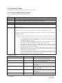
1.2 Abbreviations
Name
MB300
MB3
Channel
Device
Data Block
Group
Item
AC
MP
OS
Description
MasterBus 300
MasterBus 300 OPC server three letter abbreviation.
In MB3 OPC server, the channel represents one network connection,
e.g. one ABB Net
In MB3 OPC server, the device represents one controller
In MB3 OPC server, the Data Block represents one ABB process
object, e.g. a PIDCON
In an OPC client a group is a collection of objects that have the
configuration in common.
Each item in an OPC client represents one value, e.g. the MV for a
PIDCON collected Cyclically. All items belong to a group.
ABB Advant Controller
ABB Master Piece
ABB Operator Station
_________________________________________________________________________________________
User Manual
- 62013-06-28
2 General Information
2.1 What is MasterBus 300
MasterBus 300 is the system communication used for older ABB systems like MP280, MV230, AC410, AC 450,
IMS and OS520. It is an Ethernet communication that works in 10 MBit/s half duplex. The bus can work in a
redundant or in a non-redundant way.
The same network is used for communication between AC's and between AC and OS. This means that interlocks
etc between AC's coexist with indications to operator display.
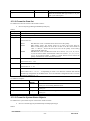
2.2 ABB Communication
ABB communication consists of three types of subscriptions.
On Event - This means that if event handling is enabled in the ABB object in the AC or MP, an update
is received every time the status word changes for the object (including analogue objects) or an order is
made towards the object. A request like this is automatically made if a Cyclic subscription is made.
Cyclic - This exists in 1, 3 and 9 second subscriptions. This means that an update is received on a
regular basis until an unsubscribe is performed.
On Demand - This means that a poll is made every time an update is requested.
In a normal operator display in ABB OS520, every object is configured for a 9 sec cyclic update together with an
event update if anything changes in the meantime. That means that if a display is opened, a 9 second subscription
is started and when the display is closed it is cancelled.
If an object dialogue is opened (pop-up for a specific object), an one second cyclic update is activated and that
one times out after about 120 seconds.
This means that for every given time, the majority of the objects have 9 sec update rate and very few have 3 or 1
second update.
If no process displays are open, then there is no update traffic continuously on the bus, except for historical trend
handling
2.2.1 Process Objects
Process objects are function blocks that exist in the ABB Controller and that is used to build up the Controller
Application.
This MB3 OPC server supports the following process object types:
AI
AO
DI
DO
PIDCON
PIDCONA
RATIO
MANSTN
VALVECON
MOTCON
MMCX
SEQ
GENUSD
GENBIN
GENCON
DAT
TEXT
TANKCON
_________________________________________________________________________________________
User Manual
- 72013-06-28
DRICONS
DRICONE
MULTIDAT
2.2.2 Data Set
Data Set is used for communication between Controllers. It consists of 24 DAT objects that are set up to be
transmitted on a regular basis between two nodes. The MB3 OPC server can be set up to use Data Sets both
receiving and sending.
2.2.3 System Objects
The ABB systems contain many system objects that are used when system pictures should be displayed. A
system picture could contain Network Status, Node Status etc. These graphical displays are automatically
generated on the OS Stations.
The MB3 OPC server contains system status objects to show system pictures for an Advant Controller 410 or
450.
2.2.4 TTD Historical Logs
These are log files that is set up in the ABB Controller through the function blocks TTDLOG and TTDVAR.
These files can later be collected for historical trending in for example IMS.
The MB3 OPC server can collect primary TTD logs and write them to Proficy Historian via the Proficy
Historian user API or write them to CSV files that can be imported.
2.2.5 Process Events
These events are used to build up the alarm list in the OS station. The handling for this is set up in the Controller.
If configured there, the event is automatically sent to all participants on the bus that has subscribed for the
events.
The MB3 OPC server has not full implementation of process events. If a process event is received then the
object sending the event is extracted and a one-shot On-Demand poll is made for that object. The MB3 A&E
OPC server can receive these events an show them with the time stamp from the controller.
The MB3 OPC server will write the process events to an internal text address. The MB3 OPC server has a buffer
that can store up to 100 process events per device. The events in the buffer are removed one by one when they
are read by a client. See 14.1.4b Device Control Item Ids. It will also be written to the MB3 OPC server window
as information text.
You can choose between 3 different Process Event Text formats. This is set up at the device level for each
controller in the MB3 Power Tool.
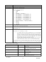
2.2.5a Format 1
This is the old format used in the 2 first versions of the MB3 OPC server.
The format of the text is:
Where:
Field
Code
“Code:%d Reason:%d from Object:%s LF:%d LR:%d with Value:%d”
Description
Property code of the event. 1 – 239 and 65502 – 65535
Examples of event codes are:
IND VALUE = 2
ERROR = 3
HI LIM2 = 4
HI LIM1 = 5
LO LIM1 = 6
_________________________________________________________________________________________
User Manual
- 82013-06-28
LO LIM2 = 7
ACT VALUE = 8
PRINT_BLK = 9
ALARM_BLK = 10
UPD_BLK = 11
DISTURBANCE = 12
See 24 Appendix D, Process Event Reasons and Codes
Reason of the event 0 - 13
Reason
NORMAL= 0
BLOCKED = 1
DEBLOCKED = 2
ALARM_ON = 3
ALARM_OFF = 4
SYS_TEXT = 5
VAL_CHANGE = 6
ACK_LIST = 7
CLEAR_PERSIST = 8
EVENT_ON = 9
EVENT_OFF = 10
STATCHK_ON = 11
UNACK_ON = 12
UNACK_OFF = 13
See 24 Appendix D, Process Event Reasons and Codes
Object name that caused the process event
Logical file number of the object that caused the process event
Logical record number of the object that caused the process event
The value sent with the process event. Can be a limit value or the actual value.
Object
LF
LR
Value
One example of a Process event text is:
Code: 5 Reason: 3 from Object CALC_AI1 LF: 6 LR:17 with Value 80,00
This is an “alarm on” event from the AI object CALC_AI1 that it’s value has passed the hi limit1 value 80,00.
2.2.5b Format 2
The different parameters of the Process Event is split with the list separator setup in the Windows control panel,
e.g. "," or ";".
The format of the text is:
Objectname,Description,Value,Unit,Reason,Property,TreatRef,GroupRef,PropTxt,EventTxt,LF,LR,Subsys,Class
Where:
Field
Objectname
Description
Value
Unit
Reason
Property
TreatRef
GroupRef
PropTxt
EventTxt
LF
Description
Object name sent with the Process Event. 1-20 characters
Object Description sent with the Process Event. 1 – 28 characters
The value sent with the Process Event. Can be a limit value or the actual value.
Unit of the value sent with the Process Event. 1 – 6 characters
Reason number sent with the Process Event. Values 0 – 13
Property code sent with the Process Event. 1 – 239 and 65502 – 65535
Treat Reference sent with the Process Event.
Group Reference sent with the Process Event.
Property Text number sent with the Process Event
Event Text number sent with the Process Event
Logical File of the object sent with the Process Event
_________________________________________________________________________________________
User Manual
- 92013-06-28
LR
SubSys
Class
Logical Record of the object sent with the Process Event
Subsystem (Process Section) of the object received with the Process Event
Class of the object received with the Process Event
One example of a Process event text when the list separator is set to ",":
"OBJECT1","OBJDESC",13.00,"hl",3,7,4,0,2,2,6,201,1,0
This is an “alarm on” event from the AI object OBJECT1 that it’s value has passed the lo limit2 value 13,00.
2.2.5c Format 3
The different parameters of the Process Event is split with the list separator setup in the Windows control panel,
e.g. "," or ";". This is the same format as format 2 with the addition that it shows the date and time in the text.
The format of the text is:
DateTime,Objectname,Description,Value,Unit,Reason,Property,TreatRef,GroupRef,PropTxt,EventTxt,LF,LR,S
ubsys,Class
Where:
Field
DateTime
Objectname
Description
Value
Unit
Reason
Property
TreatRef
GroupRef
PropTxt
EventTxt
LF
LR
SubSys
Class
Description
Received date and time of the Process Event. Format is "YYYY-MM-DD HH:MM:SS.sss"
where:
YYYY = Year
MM = Month
DD = Day
HH = Hour
MM = Minute
SS = Second
sss = Millisecond
Object name sent with the Process Event. 1-20 characters
Object Description sent with the Process Event. 1 – 28 characters
The value sent with the Process Event. Can be a limit value or the actual value.
Unit of the value sent with the Process Event. 1 – 6 characters
Reason number sent with the Process Event. Values 0 – 13
Property code sent with the Process Event. 1 – 239 and 65502 – 65535
Treat Reference sent with the Process Event.
Group Reference sent with the Process Event.
Property Text number sent with the Process Event
Event Text number sent with the Process Event
Logical File of the object sent with the Process Event
Logical Record of the object sent with the Process Event
Subsystem (Process Section) of the object received with the Process Event
Class of the object received with the Process Event
One example of a Process event text when the list separator is set to ",":
"2005-12-21 15:30:22.123","OBJECT1","OBJDESC",13.00,"hl",3,7,4,0,2,2,6,201,1,0
This is an “alarm on” event from the AI object OBJECT1 that it’s value has passed the lo limit2 value 13,00.
The process event occurred the 21st december 2005 at 15:30:22.123.
2.2.6 System Events
These events are used to build up the System Event list in the OS. The type of alarms that occur is typically
when a Node is disconnected from the Net etc.
The MB3 A&E OPC server can receive these events an show them with the time stamp from the controller.
_________________________________________________________________________________________
User Manual
- 102013-06-28
The MB3 OPC server writes these values to an internal text address. The MB3 OPC server has a buffer that can
store up to 100 system events per device. The events in the buffer are removed one by one when they are read by
a client. See 14.1.4b Device Control Item Ids. The events will also be written to the MB3 OPC server window as
information text.
The format of the text is:
Where:
Field
Event text
Event Text: Real Parameter Int Parameters Ascii Parameters Digital Parameter
Real parameter
Int Parameters
Ascii Parameters
Digital Parameter
Description
This text is received as a text index and then translated to a text from a text table inside
the MB3 OPC server. If the MB3 OPC server recieves a text index it cannot translate it
will write
“Unknown System Event Text %d” with the text index received.
1 float parameter that can be transferred together with the system event. If no real
parameter is sent then this field is blank.
Format: “RealPar: value”
2 int parameters that can be transferred together with the system event. If no int
parameters are sent then this field is blank.
Format1: “Int1: value1”
with 1 int parameter
Format2: “Int1: value1 Int2: value2”
with 2 int parameters
5 ascii parameters that can be transferred together with the system event. If no ascii
parameters are sent then this field is blank.
Format1: “Ascii1: value1”
Format2: “Ascii1: value1 Ascii2: value2”
Format3: “Ascii1: value1 Ascii2: value2 Ascii3: value3”
Format4: “Ascii1: value1 Ascii2: value2 Ascii3: value3 Ascii4: value4”
Format5: “Ascii1: value1 Ascii2: value2 Ascii3: value3 Ascii4: value4 Ascii5: value5”
1 digital parameter that can be transferred together with the system event. If no digital
parameter is sent then this field is blank.
Format: “DigPar: value”
One example of a System event text is:
MN STATUS Conn. with netw/node: Int1: 31 Ascii1: 11 Ascii2: 10
This is a system event from node 10 on network 11 that it has established a connection with node 31.
2.2.7 System Texts
If an order is illegal then the MB3 OPC server receives a system text. These texts are sent out typically when an
operator tries to set a value outside its limits.
The MB3 A&E OPC server can receive these events and show them as simple events.
The MB3 OPC server will write these system texts to an internal text address. The MB3 OPC server has a buffer
that can store up to 100 system texts per device. The texts in the buffer are removed one by one when they are
read by a client. See 14.1.4b Device Control Item Ids. The texts will also be written to the MB3 OPC server
window as warning text.
In the OPC DA interface the texts will start with a local time stamp in the format “YYYY-MM-DD
HH:MM:SS.sss”.
Every text starts with “MMI:X” where X is the MMI number the text is intended for and then follows the
received text. The text is received as a text index and is then translated to a text from a text table inside the MB3
_________________________________________________________________________________________
User Manual
- 112013-06-28
OPC server. If the MB3 OPC server receives a text index it cannot translate it will write “Unknown System text
received. Text Index [%d]” with the text index received.
_________________________________________________________________________________________
User Manual
- 122013-06-28
3 Supported Hardware
3.1 In the Local Computer
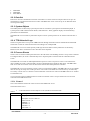
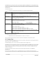
The MB3 OPC server uses a standard 802.3 Ethernet adapter. Make sure to set up the Ethernet Adapter as
described in chapter 9 Setting Up the Adapter in the Local Computer.
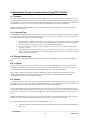
Note! We have seen problems using an integrated Ethernet adapter of the type shown in the picture below. This
type of adapter filtered some messages that are needed for the Masterbus 300 protocol to work in a right way.
3.2 In ABB
On the ABB Master side, the Masterbus 300 communication software is implemented on a microprocessorbased communication board.
DSCS 140
in MG230/1 and MP260/1, MP280/1
Communication module CS513 in processor module PM 150
in AC410
Communication module CS513 with Carrier board SC510 or SC520
in AC450
Check the ABB MasterNet Users guide for more information and see 5 Tested Communication Configurations
for tested setup in the controllers.
_________________________________________________________________________________________
User Manual
- 132013-06-28
4 Software
4.1 Supported Software
4.1.1 OPC Clients
The MB3 OPC server supports “OPC Data Access 1.0a” and “OPC Data Access 2.05” and can be accessed from
OPC clients.
4.1.2 GE Software
iFIX version 2.1 or greater
4.1.3 Operating System
Windows 2000
Windows XP
Windows 2003 server
Windows 7, 32 and 64 bit
Windows 2008, 32 and 64 bit
4.2 Required Software
4.2.1 Rawether for Windows
The Ethernet adapter is accessed via PCAUSA’s Rawether for Windows software. The following PCAUSA’s
Rawether for Windows files will be installed when the MB3 OPC server is installed.
“W32N55.DLL” to the installation directory
“MB3SP50.SYS” or “MB3SP60.SYS” in the “System32\Drivers” directory.
An Administrator must do the installation. For Windows Vista or above the setup must be executed with “Run
As Administrator” privileges.
4.2.2 In the ABB Controller
The ABB controller must be loaded with a Operator Functions module. See name of the module below:
QCxx-OPFxx
QCxx-OPFxx
QMV800
in AC410
in AC450
in MP200/1
_________________________________________________________________________________________
User Manual
- 142013-06-28
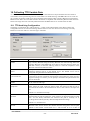
5 Tested Communication Configurations
The MB3 OPC server has been tested with ABB controllers with the following communication setup.
5.1 MB3 OPC Server
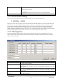
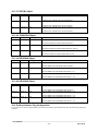
The channel settings for the MB3 OPC server communicating with the controllers have been set as below.
5.1.1 Channel Settings
Protocol
Cycle Time
Idle Tmo
Connect Tmo
Disconnect Tmo
Re-assembly Tmo
Between Ack
Credit
Retries
MB300
10
-1
1000
100
-1
3
4
3
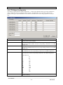
5.2 ABB Master Piece 280/1
5.2.1 Hardware
DSCS140 with Switches S10 and S11 set to F = variable frame size.
5.2.2 Software
5.2.2a Network Layer (NL)
DISTSIZE
FILTER
OVERRIDE
51
0
0
5.2.2b TL Data Base Element
PCLASS
NUMTCCB
4
132
5.2.2c TU Data Base Element
MAXSLEN
IDLET
CONT
DISCT
REAST
BTWACK
CREDIT
512
-1
1000
1000
-1
3
4
5.2.2d BM DataBase Element
BLKSIZE
LOWCLASS
HICLASS
2
700
300
5.2.2e NM Data Base Element
STASIZE
LPSIZE
4096
125
_________________________________________________________________________________________
User Manual
- 152013-06-28
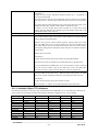
5.3 ABB Advant Controller 410
5.3.1 Hardware
CS513 with strap group S1 set to protocol type 1 = MB300 standard.
5.3.2 Software
5.3.2a Network Layer Data Base Element (NETWL)
PROT
CYCLET
DIST
FILTER
OVERRID
RECBUFF
MB300
10
51
0
0
42
5.3.2b TL Data Base Element
PCLASS
NUMTCCB
4
200
5.3.2c TU Data Base Element
MAXSLEN
IDLET
CONT
DISCT
REAST
BTWACK
CREDIT
512
-1
1000
100
-1
3
4
5.3.2d BM Data Base Element
BLKSIZE
LOWCLASS
HICLASS
2
700
300
5.3.2e NM Data Base Element
STASIZE
LPSIZE
4096
125
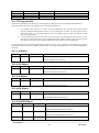
5.4 ABB Advant Controller 450
5.4.1 Hardware
CS513 with strap group S1 set to protocol type 1 = MB300 standard.
5.4.2 Software
5.4.2a Network Layer Data Base Element (NETWL)
PROT
CYCLET
DIST
FILTER
OVERRID
RECBUFF
MB300
10
51
0
0
42
_________________________________________________________________________________________
User Manual
- 162013-06-28
5.4.2b TL Data Base Element
PCLASS
NUMTCCB
4
200
5.4.2c TU Data Base Element
MAXSLEN
IDLET
CONT
DISCT
REAST
BTWACK
CREDIT
512
-1
1000
100
-1
3
4
5.4.2d BM Data Base Element
BLKSIZE
LOWCLASS
HICLASS
2
700
300
5.4.2e NM Data Base Element
STASIZE
LPSIZE
4096
125
_________________________________________________________________________________________
User Manual
- 172013-06-28
6 Application Design Considerations Using OPC Clients
6.1 General
The main design consideration that should guide the application is to minimize bus load. The MB3 OPC server
will not request any subscriptions if there aren’t any requests from any OPC clients. The startup OPC Quality of
all data blocks is Uncertain. The OPC Quality will not change until a client requests for data from a data block or
if the MB3 OPC server receives a process event that trigs a demand one shot poll of a data block.
Note! The MasterBus 300 bus load must not exceed 2000 signals per second because, if it does, the response
time increases drastically.
6.1.1 Access Time
All Data Blocks in the MB3 OPC server can have an Access Time configured. The access time handles whether
or not that type of communication should be active or not. If we look at, for example, an AI that is connected to
an operator display through 9 sec Cyclic Subscription.
When the operator display is opened, the OPC client must set the OPC Flag called Active to TRUE
for the AI Object. When the active flag is set the MB3 OPC server sets up a Cyclic subscription. At
the same time the Controller sets up an Event Subscription automatically.
As long as the operator display is open, an update is received every 9 sec and/or when an event
occurs (e.g. alarm)
When the display closes, the OPC client must set the OPC Flag called Active to FALSE for the AI
Object. Then the Access time starts to count down. When it has expired, the subscription is cleared
and the bus load is minimized.
6.2 Display Addressing
All objects in an operator display should be addressed to 9 sec Cyclic updates or an even higher On-Demand
rate.
6.2.1 Pop-up
When a pop-up is selected in a process display, then a specific bit in the MB3 OPC server for the data block
should be set (Data Block Control Item !C_FAST). That bit tells the MB3 OPC server to subscribe for Fast
Cyclic updates. After two minutes the fast cyclic updates falls back to normal cyclic updates.
If any orders is made in the pop-up, then the bit should be set again to reset the two minutes timer for fast
updates. If the display is closed, the bit that trigs for Normal Cyclic updates (Data Block Control Item
!C_NORMAL) should be set to minimize bus load.
6.3 Alarms
All items that should generate alarms in the client system should be addressed to the status bits of the object with
the subtype set to “E” = the Event address in the MB3 OPC server. If an operator display is active at the time of
the alarm, then there is an active Event Subscription and the object will be updated.
If no operator display is open, then the MB3 OPC server will receive a Process Event. When that occurs, there
will be a one-shot On-Demand poll for the object that sent out the Process Event. You can turn off the Demand
poll option per controller if you don't want the MB3 OPC server to do demand polls when it receives process
events.
Note! If the MB3 OPC server receives many process events within one second from the same obejct it will not
manage to do a demand poll for each of those events, but at least one demand poll will be sent.
This means that there are two requirements for making alarms work:
All Process Objects that should be able to generate alarms/events must be configured in the MB3
OPC server.
_________________________________________________________________________________________
User Manual
- 182013-06-28
All alarm conditions should be configured and generated in the ABB Controller and not on the
client side. This means that if a limit alarm for an AI is requested, that should be set up in the
Controller so that the controller sends the alarm event driven. One should never collect a process
object continuously and then set the limits on the client side. This will cause too much bus load.
6.4 Continuously Update of Object
6.4.1 Historical Trends
Most signals should be connected with a 30 sec On-Demand polling. The rest could normally be connected to 9
sec Cyclic request. Primary TTD logs can be collected and written to Proficy Historian via the Proficy Historian
user API or written to CSV files that can be imported.
One should always be aware of the bus load that historical values generate.
6.5 Sending Orders to Objects
Before you can send any orders to a object in the ABB controller the object has to be selected. Each object type
except DAT objects has a selected bit. This bit can typically be used in object pop-up pictures. When you open a
pop-up picture for an object the selected bit can be set and then you can do your orders to the object. When you
close the pop-up picture for the object you must do deselect to let other nodes access the object.
You can use the datablock control Item ID “!ORDER_MMI:Name” to control the MMI number 1 – 4 to use
when sending orders to the object configured in the datablock. Default the MB3 OPC server uses MMI number
1.
Selection and deselection is taken cared of automatically in the MB3 OPC server when sending orders to DAT
objects. The MB3 OPC server first selects the DAT object, then sends the VALUE order and finally deselects
the DAT object. DAT objects always uses MMI number 1.
6.6 Continuously Order to Object
This type of communication normally invokes data mirroring between different brands of PLC Systems. This
could also apply to supervisory control systems.
This type of orders should be handled through Data Set communication to minimize bus load. If this not is
possible DAT objects are the best solution for data mirroring.
Note! If you use DAT booleans for data mirroring then have separate DAT booleans for reading and writing to
avoid that bits are overwritten with old data. DAT booleans are written with all 32 bits in one message.
6.7 Building the MB3 OPC Server Configuration
If a node sends out a request for a name translation of an object name that does not exist in any database on the
MB300 network then this name translation request will be sent around on the network forever. The only way to
remove those name translation requests from the network is to use special software from ABB. The best way to
avoid non-existent object names in your configuration is to create a CSV configuration file that is based of object
names from reported BAX files from the ABB controllers. The BAX file is a text file dump of the database in a
controller.
_________________________________________________________________________________________
User Manual
- 192013-06-28
7 Application Design Considerations Using FIX
7.1 General
The main design consideration that should guide the application is to minimize bus load. The MB3 OPC server
will not request any subscriptions if there aren’t any requests from database blocks from FIX database. The
startup Quality of all data blocks is Uncertain. The OPC Quality will not change until a FIX database block
requests for data from a data block or if the MB3 OPC server receives a process event that trigs a demand oneshot poll of a data block.
Note! The MasterBus 300 bus load must not exceed 2000 signals per second because, if it does, the response
time increases drastically.
7.1.1 Access Time
Use Analog Register and Digital Register database blocks for all values in process displays. All Data Blocks in
the MB3 OPC server can have an Access Time configured. The access time handles whether or not that type of
communication should be active or not. If we look at, for example, an AI process object that is connected to an
operator display through 9 sec Cyclic Subscription.
When the operator display is opened the Analog Register or Digital Register database block
accesses the AI Object data block. When the data block is accessed the MB3 OPC server sets up a
Cyclic subscription. At the same time the Controller sets up an Event Subscription automatically.
As long as the operator display is open, an update is received every 9 sec and/or when an event
occurs (e.g. alarm)
When the operator display closes the Analog Register or Digital Register stops accessing the AI
Object data block. Then the Access time starts to count down. When it has expired, the subscription
is cleared and the bus load is minimized.
7.2 Display Addressing
All objects in an operator display should be addressed to 9 sec Cyclic updates or an even higher On-Demand rate
used together with Analog or Digital Register database blocks.
7.2.1 Pop-up
When a pop-up is selected in a process display, then a specific bit in the MB3 OPC server for the data block
should be set (Data Block Control I/O address !C_FAST). That bit tells the MB3 OPC server to subscribe for
Fast Cyclic updates. After two minutes the fast cyclic updates falls back to normal cyclic updates.
If any orders is made in the pop-up, then the bit should be set again to reset the two minutes timer for fast
updates. If the display is closed, the bit that trigs for Normal Cyclic updates (Data Block Control I/O address
!C_NORMAL) should be set to minimize bus load.
7.3 Alarms
All database blocks that should generate alarms in the FIX system should be addressed to the status bits of the
object with the subtype set to “E” = the Event address in the MB3 OPC server. If an operator display is active at
the time of the alarm, then there is an active Event Subscription and the object will be updated.
If no operator display is open, then the MB3 OPC server will receive a Process Event. When that occurs, there
will be a one-shot On-Demand poll for the object that sent out the Process Event. You can turn off the Demand
poll option per controller if you don't want the MB3 OPC server to do demand polls when it receives process
events.
Note! If the MB3 OPC server receives many process events within one second from the same obejct it will not
manage to do a demand poll for each of those events, but at least one demand poll will be sent.
This means that there are two requirements for making alarms work:
_________________________________________________________________________________________
User Manual
- 202013-06-28
All Process Objects that should be able to generate alarms/events must be configured in the MB3
OPC server.
All alarm conditions should be configured and generated in the ABB Controller and not on the
client side. This means that if a limit alarm for an AI is requested, that should be set up in the
Controller so that the controller sends the alarm event driven. One should never collect a process
object continuously and then set the limits on the client side. This will cause too much bus load.
7.4 Continuously Update of Object
7.4.1 Historical trends
Most signals should be connected with a 30 sec On-Demand polling. The rest could normally be connected to 9
sec Cyclic request. Primary TTD logs can be collected and written to Proficy Historian via the Proficy Historian
user API or written to CSV files that can be imported.
One should always be aware of the bus load that historical values generate.
7.5 Sending Orders to Objects
Before you can send any orders to a object in the ABB controller the object has to be selected. Each object type
except DAT objects has a selected bit. This bit can typically be used in object pop-up pictures. When you open a
pop-up picture for an object the selected bit can be set and then you can do your orders to the object. When you
close the pop-up picture for the object you must do deselect to let other nodes access the object.
You can use the datablock control I/O address “!ORDER_MMI:Name” to control the MMI number 1 – 4 to use
when sending orders to the object configured in the datablock. Default the MB3 OPC server uses MMI number
1.
Selection and deselection is taken cared of automatically in the MB3 OPC server when sending orders to DAT
objects. The MB3 OPC server first selects the DAT object, then sends the VALUE order and finally deselects
the DAT object. DAT objects always uses MMI number 1.
7.6 Continuously Order to Object
This type of communication normally invokes data mirroring between different brands of PLC Systems. Could
also apply to supervisory control systems.
This type of orders should be handled through Data Set communication to minimize bus load. If this not is
possible then DAT objects are the best solution for data mirroring.
Note! If you use DAT booleans for data mirroring then have separate DAT booleans for reading and writing to
avoid that bits are overwritten with old data. DAT booleans are written with all 32 bits in one message.
7.7 Building the MB3 OPC Server Configuration
If a node sends out a request for a name translation of an object name that does not exist in any database on the
MB300 network then this name translation request will be sent around on the network forever. The only way to
remove those name translation requests from the network is to use special software from ABB. The best way to
avoid non-existent object names in your configuration is to create a CSV configuration file that is based of object
names from reported BAX files from the ABB controllers. The BAX file is a text file dump of the database in a
controller.
_________________________________________________________________________________________
User Manual
- 212013-06-28
8 Installation
8.1 Licensing Software
This software is needed for the MB3 OPC server to find the hardware key installed on the machine. If the MB3
OPC server can’t find the hardware key then it will run in Demo mode for two hours.
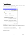
Run the “ProficyLicensing_x_y_z.exe” file from the Licensing folder on the MB3 OPC server installation CD.
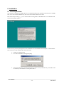
The following dialog appears.
Click on Yes if you accept the agreement. All needed files will be installed on the computer. To check that the
files has been correctly installed then do the following:
Plug in your hardware key
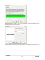
Go to the command line and type ikeydiag
Click on the OK button. If all licensing files have been correctly installed then you should be able
to see the key serial number as in the picture below.
_________________________________________________________________________________________
User Manual
- 222013-06-28
8.2 MB3 OPC Server Installation
An Administrator must do the installation. For Windows Vista or above the setup must be executed with “Run
As Administrator” privileges.
Run “Setup.exe” from the Disk folder on the MB3 OPC server installation CD. The following dialog appears:
Click on the Next button.
_________________________________________________________________________________________
User Manual
- 232013-06-28
Read the license agreement carefully. If you accept the license agreement then Click on the Next button else end
the installation with a Click on the Cancel button
Enter the installation directory and click on the Next button. If iFix is installed then iFix directory will be the
default directory.
_________________________________________________________________________________________
User Manual
- 242013-06-28
Select Server or Client installation and click on the Next button.
If iFix is installed then you will be prompted to enter the FIX node name where you want to install the MB3
OPC server. If iFix not is installed this dialog will not be showed. Enter Node name and Click on the Next
button.
_________________________________________________________________________________________
User Manual
- 252013-06-28
Enter the Program folder, in Windows Start menu, where you want to place the MB3 Power Tool icon and help
file and then click on the Finish button.
The installation is ready. Click on the Done button.
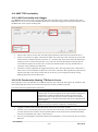
8.3 MB3 OPC Server Registration
The server needs to be registered together with the specific hardware key it was ordered for to run properly. If
the server not is registered then it will run in demo mode for two hours.
Start the MB3 Power Tool to register your MB3 OPC server. The startup dialog contains a button named “Server
Password…”
_________________________________________________________________________________________
User Manual
- 262013-06-28
Click on the “Server Password…” button and the dialog box below shall appear.
Your actual hardware key serial number is shown in the dialog. Check that this number matches with the number
you ordered the server license for. Enter the server password for your server in the server password field. Click
on the OK button to save the server password.
If you have entered the right server password then status text OK will appear when the server is started.
If you have entered wrong server password or have wrong key installed then a status text telling that the server
runs in demo mode will appear.
_________________________________________________________________________________________
User Manual
- 272013-06-28
If your configuration contains more objects (Data Blocks) than your server license accepts then the server will
run in demo mode and show the following status text.
_________________________________________________________________________________________
User Manual
- 282013-06-28
9 Setting Up the Adapter in the Local Computer
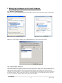
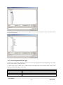
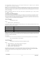
9.1 Network Configuration
Make sure to only have the MB3 NDIS protocol checked for the Local area connection as shown in the pictures
below.
MB3 NDIS 5.x for XP and Win 2003
MB3 NDIS 6.x for Vista and later
Make sure to set the Adapters Media Type to 10Mb Half duplex as shown in the picture below.
9.2 Adapter MAC Address
The Ethernet adapters MAC address must have the syntax “00:00:23:00:XX:00” where XX is the Masterbus 300
node number of the local computer in hexadecimal format. Make sure to set the Local computer node number
under channel settings in MB3 Power Tool to the same node number. One example: If you want your local
computer to have node number 31 on the Masterbus 300 network then the MAC address of the adapter shall have
the following format: “00:00:23:00:1F:00” where 1F is the node number 31 in hexadecimal notation. There are
two ways to override the hardware MAC address of the ethernet adapter.
_________________________________________________________________________________________
User Manual
- 292013-06-28
Note! If the MAC address doesn’t match with the ABB format then the MB3 OPC server will not start. If the
Local node number configured under the channel settings doesn’t match with the MAC address then the MB3
OPC server will not start.
9.2.1 Method 1
This method is used if your adapter supports Clone MAC address under the network settings. If you have an
adapter that doesn’t support Clone MAC address under the network settings, then you have to go to the second
method.
1.
2.
3.
4.
5.
6.
7.
Go to Start->Settings->Control Panel and double click on Network and Dial-up Connections.
Right click on the Adapter you want to change the MAC address for and click on properties.
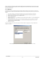
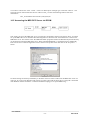
Under “General” tab, click on the “Configure” button
Click on “Advanced” tab
Under “Property section”, you should see an item called “Network Address” or "Locally Administered
Address", click on it.
On the right side, under “Value”, type in the New MAC address you want to assign to your adapter.
Usually this value is entered without the “:“ between the MAC address numbers. Save your new
settings and leave the network settings.
Reboot your system.
In the two example pictures below both property “Network Address” and property “Locally Administered
Address” are shown.
In the example shown above the node number of the adapter is set to 37 hex = 55 dec.
_________________________________________________________________________________________
User Manual
- 302013-06-28
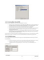
In the example shown above the node number of the adapter is set to 20 hex = 32 dec.
9.2.2 Method 2
Not all adapters let you set the MAC address in its advanced settings. Then there is a possibility to set it via the
registry.
1.
2.
3.
Go to Start->Settings->Control Panel and double click on Network and Dial-up Connections.
Right click on the Adapter you want to change the MAC address for and click on properties.
Under “General” tab, click on the “Configure” button. Record the Description for the Adapter you
want to change. In the picture below it is ”3Com 3C920 Integrated Fast Ethernet controller”.
4.
5.
Go to Start -> Run, type “regedit” to start registry editor.
Go to “HKEY_LOCAL_MACHINE\SYSTEM\CurrentControlSet\Control\Class\{4D36E972-E32511CE-BFC1-08002BE10318}. Double click on it to expand the tree. The subkeys are 4-digit numbers,
which represent particular network adapters. You should see it starts with 0000, then 0001, 0002, 0003
and so on.
_________________________________________________________________________________________
User Manual
- 312013-06-28
6.
7.
8.
Go through each subkey that starts with 0000. Click on 0000, check DriverDesc keyword on the right
to see if that's the Adapter you want to change the MAC address for. The DriveDesc should match the
Description you recorded from step 3. If there is no match, then move on to 0001, 0002, 0003, and so
on, until you find the one you want. Usually 0000 contains the first Adapter you installed on the
computer. In this demonstration, 0000 is the Adapter selected.
Once you selected the subkey (i.e. 0000), check if there is a keyword "NetworkAddress" that exist in
the right side of the window.
If "NetworkAddress" keyword does not exist, then create this new keyword:
Click on the drop down menu “Edit -> New -> String Value”.
Set the name of the string value to ”NetworkAddress”
Double click on the ”NetworkAddress” name and enter the new MAC address you want to
use. Then click OK. (There should not be any "-" in this address. Your entry should only
consist of 12 digits as seen in the figure below)
_________________________________________________________________________________________
User Manual
- 322013-06-28
9.
If "NetworkAddress" keyword exists, make sure the keyword type is REG_SZ. This keyword might
not have a value at this time.
Double click on the keyword NetworkAddress and the String Editor window will pop up.
Enter the new MAC address you want to use. Then click OK. (There should not be any "-" in this
address. Your entry should only consist of 12 digits as seen in the figure above)
10. There are 2 ways to make the new MAC address active. Either Reboot your system or follow the steps
below.
Goto Start->Setting->Control Panel, and double click on ”Network and Dial-up Connections".
Select the Network Adaptor for which you just changed the MAC address.
Right click on the selected Network Adaptor and click "Disable." Verify the status column for this
adaptor changes to "Disabled"
Right click on the selected Network Adaptor and click "Enable.” Verify the status column for this
adaptor changes to "Enabled"
If for any reason it cannot be disabled or re-enabled, you have to reboot your system to make the
changes effective.
9.2.3 Restore the TRUE Hardware Burned-in MAC Address
You maybe for some reason want to restore the hardware burned in MAC address of your adapter.
If you followed Method 1, then go back to the advanced properties window and remove the entry you added.
If you followed Method 2, then remove the "NetworkAddress" keyword you added in the registry.
Reboot the computer to activate the change you made.
_________________________________________________________________________________________
User Manual
- 332013-06-28
10 Event Treat File and Unacknowledge of Object Alarms
When the MB3 OPC server is installed an Event Treat file, "MB3_Event_Treatments.txt", is copied to the
installation directory. When the MB3 OPC server is started it tries to read this Event Treat file. The parameters
AL_TOBLK and AL_FRBLK for each Event Treat block in the file will decide how the MB3 OPC server sends
unackowledge back to the ABB controllers when it receives new object alarm Process Events. The behavior of
the MB3 OPC server will be:
1.
2.
3.
4.
5.
If the MB3 OPC server can't find the "MB3_Event_Treatments.txt" file when it starts then no object alarm
Process Event will be unacknowledged from the MB3 OPC server.
If the MB3 OPC server receives an object "alarm on" Process Event and the parameter AL_TOBLK in the
Event Treat block the process event belongs to is set to NO, then an unacknowledge for this object will be
sent to the ABB controller.
If the MB3 OPC server receives an object "alarm on" Process Event and the parameter AL_TOBLK in the
Event Treat block the process event belongs to is set to YES, then no unacknowledge for this object will be
sent to the ABB controller.
If the MB3 OPC server receives an object "alarm off" Process Event and the parameter AL_FRBLK in the
Event Treat block the process event belongs to is set to NO, then an unacknowledge for this object will be
sent to the ABB controller.
If the MB3 OPC server receives an object "alarm off" Process Event and the parameter AL_FRBLK in the
Event Treat block the process event belongs to is set to YES, then no unacknowledge for this object will be
sent to the ABB controller.
If you don't want the MB3 OPC server to send any unacknowledges for any object alarms then you can either
rename the "MB3_Event_Treatments.txt" file or set all AL_TOBLK and AL_FRBLK parameters in the file to
YES. You must restart the MB3 OPC server before it will try to read the file again.
_________________________________________________________________________________________
User Manual
- 342013-06-28
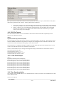
11 MB3 Power Tool
The MB3 Power Tool is your main configuration utility for setting up and maintaining the MB3 OPC server. It
provides fields for specifying the properties of channels, devices, and data blocks.
The Power Tool provides:
The Template dialog box for specifying channel, device, and data block defaults.
The Setup dialog box for defining the default name and default path for configuration files.
The Server Connection dialog box for connecting to a remote or local OPC server.
The Tree Browser for an overall view of your system configuration.
A movable Tree Browser and toolbars.
A Statistics View for displaying the statistics of your server while it is running. Statistics are provided for
levels: channel, device, and data block.
A Configuration View for displaying and modifying driver, channel, device, and data block properties.
Access Methods
From the Windows Start menu
Select Programs from the Start menu.
Select the folder selected during installation from the Programs submenu.
Select MB3 Power Tool from the submenu.
From FIX Database Builder
Select MB3 from the Drivers menu.
From the FIX System Configuration Utility (SCU)
Select SCADA from the Configure menu.
Double-click your OPC server from the Configured I/O Drivers list box.
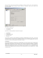
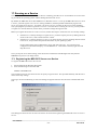
When you first start the Power Tool, the Server Connection dialog box appears. This dialog box lets you choose
the OPC server that the Power Tool communicates with. You can choose either the Local Server (on your
computer) or a Remote Server (on the network).
_________________________________________________________________________________________
User Manual
- 352013-06-28
Once you choose an OPC server, the Power Tool attempts to connect to the OPC server. If the connection is
successful, a message appears telling you that the connection is established. Then the main window of the
Power Tool appears.
This window is comprised of:
The Properties Viewer
The Menu Bar
By default, the following additional components also appear:
Tree Browser
Main Toolbar
Configuration Toolbar
Run-time Toolbar
Status Bar
You can show or hide any of the components by selecting a command from the View menu. You can also
customize the Power Tool’s appearance by dragging the toolbars or the Tree Browser to the location you want.
You can also make the toolbars or the Tree Browser float above the Power Tool by dragging them to the center
on the screen. Later, you can dock them or resize them, as needed.
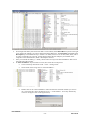
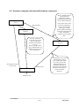
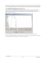
Tree Browser
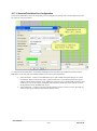
The Tree Browser displays a hierarchical list of the MB3 OPC server and its channels, devices, and data blocks.
The MB3 OPC server appears at the top of the tree. When you select an item in the Tree Browser, its properties
display in the Properties Viewer. You can choose to view the item's configuration or statistics properties by
clicking buttons on the Run-time toolbar. All data blocks are sorted by name in the tree. The data blocks have
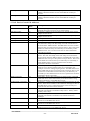
different icons depending of the object type, if its symbolic name is translated or not, if communication is good
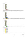
or bad and if the configured object type matches the name translated object type. See examples below. Use F5
to refresh the Tree.
_________________________________________________________________________________________
User Manual
- 362013-06-28
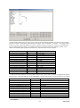
An AI object with object name AI1.1 that hasn’t been translated has the shape of a rectangle with red color.
An AI object with object name AI1.1 that has been translated but communication is bad or uncertain has the
shape of a rectangle with yellow color.
An AI object with object name AI1.1 that has been translated and the communication is good has the shape of a
circle with green color.
_________________________________________________________________________________________
User Manual
- 372013-06-28
An object that is configured as one object type and reported as another object type from the controller during
name translation is marked with a error symbol in the browser tree. No subscriptions will be sent for the obejct
until it is configured with the right type. Check the statisitcs for the object to see the name translated object type.
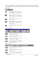
Main Toolbar
Same as Menu File New. Creates a new
empty configuration. This is not allowed
when the MB3 OPC server is started.
Same as Menu File Open. Open a
configuration file or a CSV import file.
This is not allowed when the MB3 OPC
server is started.
Same as Menu File Save. Saves the
configuration file.
Same as Menu File Save As. Lets you
enter a filename to save the file as. Can
either be saved as a configuration file or as
a reported CSV file.
Same as Menu Help Help Topics. Opens a
Help file.
Configuration Toolbar
Same as Menu Edit Add Channel. Adds a
Channel to the configuration.
Same as Menu Edit Add Device. Adds a
Device to the configuration.
Same as Menu Edit Add Data Block. Adds
a Data Block to the configuration.
Same as Menu Edit Delete. Deletes the
selected Channel, Device or Data Block
from the configuration.
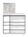
Runtime Toolbar
Same as Menu Display Mode Start. Starts
the MB3 OPC server.
Same as Menu Display Mode Stop. Stops
the MB3 OPC server.
Same as Menu Display Mode Config
Mode. Shows the configuration window
_________________________________________________________________________________________
User Manual
- 382013-06-28
for the selected Channel, Device or Data
Block.
Same as Menu Display Mode Stats Mode.
Shows the statistics window for the
selected Channel, Device or Data Block.
Same as Menu Options Reset Counters.
Resets the counters in the statistics
window for the selected Channel, Device
or Data Block. This button is only
accessible when the Power Tool is in
Statistics Mode. Click the Statistics button
shown above to enable Statistics Mode.
Same as Menu Options Templates. Opens
the Templates dialog where default
configuration values can be set for
Channel, Device and Data Block.
Same as Menu Options Setup Lets you
select the way the Power Tool displays
statistics, enter defaults for the MB3 OPC
server configuration file name and path,
and make advanced settings.
Same as Menu Options OLE server. Let
you select an OLE server.
Same as Menu Options DataScope.
Displays the data scope for this MB3 OPC
server. Any objects that have the data
scope enabled send messages to this
window.
Same as Menu Options Show Server.
Shows or hides the MB3 server window.
At startup the MB3 server window is
hidden. If the MB3 OPC server is running
as a service then the window cannot be
shown.
_________________________________________________________________________________________
User Manual
- 392013-06-28
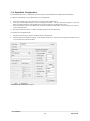
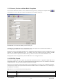
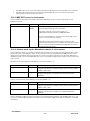
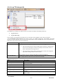
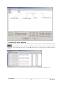
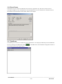
11.1 Setting Up the Power Tools and MB3 OPC Servers Environment
You can set up the environment by displaying the Setup dialog box and completing each tab. The Setup dialog
box lets you do the following:
Set the statistics refresh rate.
Set the default configuration file name and default path for the configuration file. This is the configuration file
the MB3 OPC server will use when it is started.
_________________________________________________________________________________________
User Manual
- 402013-06-28
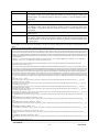
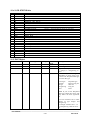
Make advanced settings for your MB3 OPC server. Advanced settings are for fine-tuning your MB3 OPC server
and should not be changed unless you have an intimate knowledge of how the MB3 OPC server operates and
know that you need to make some adjustments.
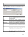
Field
Memory –
Maximum Size
Memory –
Growth Increment
Memory –
Overrun Buffer
Alarm & Event Queues –
Max Process Events
Description
Specifies the maximum amount of memory that the MB3 OPC server requires.
The amount of memory specified is allocated and reserved, but not committed
until needed. The MB3 OPC server rounds up the value you enter to the
nearest value supported by your operating system. Each data block requires
520 bytes of memory. Each device allocates 2800 * 371 = 1038800 bytes of
memory for its AC system objects. This means that with the default maximum
size 30000000 bytes and if you have 10 devices in your configuration a
maximum of around 37700 data blocks can be allocated. If you need more
data blocks the maximum size has to be increased.
Default Value
30000000 bytes
Specifies the increment that MB3 OPC server memory grows by when more
memory is needed. The MB3 OPC server rounds up the value you enter to the
nearest value supported by your operating system.
Default Value
4095 bytes
Specifies an area of memory that immediately follows MB3 OPC server main
memory and is defined by the Maximum Size field. The MB3 OPC server
rounds up the value you enter to the nearest value supported by your operating
system. If you try to access memory in this area, an error is generated. You
will also experience problems with your MB3 OPC server if your system
attempts to use memory in the overrun buffer.
Default Value
4095 bytes
How many Process Events, the MB3 DA OPC server can store when no MB3
A&E OPC server is connected to it. When a MB3 A&E OPC server connects
the stored events will be sent to it one by one. Set to 0 to disable the queueing
of events.
If you make changes to the value then you must restart the MB3 DA OPC
server before it will take effect.
_________________________________________________________________________________________
User Manual
- 412013-06-28
Alarm & Event Queues –
Max System Events
Alarm & Event Queues –
Max System Texts
Path to signal conditioning dll
Path to Error Resource dll
Simulation Mode
Default Value:
200
How many System Events, the MB3 DA OPC server can store when no MB3
A&E OPC server is connected to it. When a MB3 A&E OPC server connects
the stored events will be sent to it one by one. Set to 0 to disable the queueing
of events.
If you make changes to the value then you must restart the MB3 DA OPC
server before it will take effect.
Default Value:
100
How many System Texts, the MB3 DA OPC server can store when no MB3
A&E OPC server is connected to it. When a MB3 A&E OPC server connects
the stored events will be sent to it one by one. Set to 0 to disable the queueing
of events.
If you make changes to the value then you must restart the MB3 DA OPC
server before it will take effect.
Default Value:
50
Specifies the path to the DLL that provides signal conditioning for the MB3
OPC server (most likely MB3SIG.DLL). Do not make entries in this field
unless you are having problems finding the signal conditionings.
Specifies the path to the DLL that provides all the error codes and text error
messages for the MB3 OPC server. Windows also uses this DLL to provide
messages to the Event Viewer.
On - Enables simulation mode for the MB3 OPC server. All writes go directly
to the data blocks instead of the process hardware.
Off – Disables simulation mode for the MB3 OPC server. All writes go
directly to the process hardware.
Auto Create
Default
Off
On - Let you create data blocks automatically. When a client application
attempts to access a non-existent data block, the current data block expands, if
possible, or the MB3 OPC server creates a new data block.
Off – Prohibits you from creating data blocks automatically from clients. If
this option is selected, you must use the Power Tool to create data blocks.
Default
Off
Auto Start
On - Lets the MB3 OPC server automatically start polling the process
hardware for data. When you set up the MB3 OPC server to run as a service,
this option lets the MB3 OPC server collect data immediately on startup.
Off - Prohibits the MB3 OPC server from collecting data automatically. As a
result, you must start the MB3 OPC server yourself, or use FIX to start it for
you.
CSV File Options –
Save Name Translations
Default
Off
On – The name translated Logical File, Logical Record and Objecttype are
saved to the CSV file for the datablocks.
Off – No name translations are saved to the CSV file.
Default
_________________________________________________________________________________________
User Manual
- 422013-06-28
Off
If your OPC client only support the OPC Data Access 1.0a standard then check the checkbox under the OPC tab.
Default it is unchecked.
_________________________________________________________________________________________
User Manual
- 432013-06-28
11.2 Channel Configuration
A channel object represents one network connection with the MB3 OPC server’s local node number.
To add a new channel to your MB3 OPC server configuration
1.
2.
3.
Click the Add Channel button on the Configuration toolbar. The new channel appears in the Tree Browser
and the fields for entering channel properties appear in the Properties Viewer.
Enter the properties for the new channel. Edits to a field do not take effect until you remove the focus (or
cursor) from the field.
Select the Enable check box to enable communication for the new channel.
To modify an existing channel
1.
2.
Select the channel you want to modify from the Tree Browser.
Edit the channel’s fields as needed.
Note! Do not modify any channel fields when the MB3 OPC server is started.
Field
Name
Description
Enabled
Description
Specifies the name of the selected channel.
Up to 30 alphanumeric characters, including underscores ( _ ) and
hyphens ( - ).
Lets you enter text about the selected channel. Entries in this field can
be very helpful when you go back to look at old configuration or report
files, or when you need to modify an existing configuration. The more
detailed and specific the information you enter in this field, the easier
it is to identify the channel.
Up to 40 alphanumeric characters and symbols.
Enables the MB3 OPC server to communicate through this channel. If
you clear the check box, the MB3 OPC server does not communicate
on this channel.
_________________________________________________________________________________________
User Manual
- 442013-06-28
Node
Primary and
Network
The MB300 node number that the MB3 OPC server is set up to use on
this channel. This node number must match the MAC address of the
Adapter configured for this channel.
Backup
Network
–
Valid entries are 1 – 127
The MB300 network number that the Adapter is connected to.
Valid entries are 11 – 99 and 111 – 119
Primary and
Adapter
Backup
Network
–
Primary and Backup Network –
Protocol
Primary and Backup Network – Cycle
Time
Primary and Backup Network – Idle
Tmo
Backup
Network
–
Primary and Backup
Disconnect Tmo
Network
–
Primary and
Connect Tmo
Primary and Backup Network – Reassembly Tmo
Primary and
Between Ack
Backup
Network
–
Primary and Backup Network – Credit
Primary and
Retries
Backup
Data Set Bit Numbering
Network
–
If no backup is used then set it to blank which will set it to None.
The Adapter in the Local Computer that is connected to the MB300
network The list box contains all adapters of 802.3 type in the
computer. Make sure the adapter is set up as described in section “4
Setting up the Adapter in the Local Computer”. If backup is used then
both primary and backup adapter should have the same MAC address.
The protocol used by this Adapter. Only MB300 standard can be
chosen right now.
Routing transmit cycle time. Controls the generation of routing
messages sent on the network from the MB3 OPC server. Default
value 10 generates one message per second.
Valid entries are 10 – 127
Specifies how long time a transport connection with low or medium
priority is allowed to be unused while in data transfer state. If it expires
the transport connection disconnects. Expressed in 10ms units.
Default is –1 = infinite.
Transport connection request timeout. Specifies the maximum time to
wait for a transport connection to be established when the MB3 OPC
server has requested a connection. Expressed in 10ms units. Default is
1000.
Transport disconnect timeout. Specifies the maximum time a transport
connection is allowed to be in the disconnecting state when the MB3
OPC server has requested a disconnection. Expressed in 10ms units.
Default is 100.
Re assembly timeout. Maximum time that can elapse before a
Transport Service Data Unit (TSDU) is successfully re-assembled on a
transport connection with low or normal priority. If it expires the
transport connection is disconnected. Expressed in 10ms units. Default
= –1 which means infinite.
Between Acknowledgement. Specifies for low and normal priority
transport connections when it is time to send an acknowledgment with
new credit to allow the sending node to continue to send. Expressed in
number of received Transport Protocol Data Units (TPDU). Default
value is 3.
Valid entries 1 – 15
Credit. Specifies the maximum number of TPDUs that the MB3 OPC
server allows other nodes to send on a transport connection with low or
normal priority. Default value is 4.
Valid entries 1 – 15
Number of times a TPDU is resent without acknowledgement before
the MB3 OPC server considers that the telegram has failed.
Default is 3.
Valid entries 1 – 9
Selects how to address data set bits in the I/O Address in a Fix
database block or in the Item ID in a OPC client.
Valid values are:
0 – 31
_________________________________________________________________________________________
User Manual
- 452013-06-28
1 – 32
Default is 0 – 31.
A click on this button opens up the TTD Archiving dialog.
TTD Archiving…
11.2.1 TTD Archiving
This dialog contains the configuration of how the collected TTD logs shall be archived. You can choose to store
the logs to Proficy Historian via the user API or to store the logs to CSV files.
Field
iHistorian User API Enable
iHistorian User API Server
iHistorian User API User / Password
iHistorian CSV Files Enable
iHistorian CSV Files Temp Path
iHistorian CSV Files File Path
iHistorian CSV Files Interval
Description
Enable this check box if you want the MB3 OPC server to write the collected TTD
logs to Proficy Historian using the Proficy Historian user API. The tags must exist
in Proficy Historian. If the MB3 OPC server fails to write the TTD log via the user
API then it will try to write the TTD log values to a CSV file irrespective of the
iHistorian CSV Files Enable flag .
Proficy Historian server name to connect to. If the field is left blank, then the
connection attempt will be to the default server. The default server can be
configured using the Historian administration tool.
If left empty, then the username that owns the process is used. Most of the time this
is the same as the user logged into the operating system. However, in the case of a
program running as a service you can specify a username and password that the
process should use.
Enable this check box if you want the MB3 OPC server to create CSV archive files
for the collected TTD logs.
The MB3 OPC server creates the collected TTD logs CSV archive files in this
folder. When the TTD Archiving Interval timer has timed out then the file is
moved from this folder to the File Path from where a file collector can import the
file.
Default is "C:\TTDArchive\Temp".
The path to where the CSV archive files created in the Temp Path shall be moved
when the Interval time has timed out. A file collector can import the files from this
path . For the Proficy Historian File Collector this path is normally set to
"C:\Program Files\Proficy\Proficy Historian\ImportFiles\Incoming".
Default is "C:\TTDArchive".
The time in seconds that the MB3 OPC server will wait before it moves any
iHistorian CSV archive file for this channel from the temp path to the file path.
Default is 300 seconds. Valid values are 0 – 900 seconds. If set to 0 then an
interval of 500ms will be used.
_________________________________________________________________________________________
User Manual
- 462013-06-28
11.2.2 Override Local Node, Network Number and Adapter Name
When the MB3 OPC server is installed there is created a key in the registry called
"HKEY_LOCAL_MACHINE\SOFTWARE\Novotek\Drivers\MB3\Redundancy". Under this key there are two
DWORD values and one String value with default settings as described in the table below.
Value
ChannelLocalNode
ChannelPrimNetwork
ChannelPrimAdapter
Description
DWORD value with default settings 0.
DWORD value with default settings 0.
String value with default settings empty string.
If any of these values are set with a valid value then they will override what is set in the mb3 configuration file
when the MB3 OPC server is started. The default values will not override the values set in the mb3 configuration
file.
This can be useful if you have two machines with identical configurations except these three values and want to
copy the configuration files between the two machines.
Note! If you use primary and backup networks then don’t use these registry settings!
_________________________________________________________________________________________
User Manual
- 472013-06-28
11.3 Device Configuration
A device object represents a node on the Masterbus 300 network.
To add a new device to your MB3 OPC server configuration
1.
2.
3.
4.
From the Tree Browser, select the channel you want to add the device to.
Click the Add Device button on the Configuration toolbar. The new device appears in the Tree Browser and
the fields for entering device properties appear in the Properties Viewer.
Enter the properties for the new device. Edits to a field do not take effect until you remove the focus (or
cursor) from the field.
Select the Enable check box to enable communication for the new device.
To modify an existing device
1.
2.
Select the device you want to modify from the Tree Browser.
Edit the device’s fields as needed. The device updates automatically.
Note 1! If the MB3 OPC server receives a routing message from a node not in its configuration then it will add a
device representing that node automatically to its configuration.
Note 2! You are not allowed to remove any devices or to change the node number when the MB3 OPC server is
started.
Field
Name
Description
Description
Specifies the name of the selected device. Any application requesting
data from the MB3 OPC server uses this name to access points on the
device. Each device that the MB3 OPC server communicates with
should have a unique device name regardless of the device’s channel.
Up to 30 alphanumeric characters including underscores ( _ ) and
hyphens ( - ).
Contains text about the selected device. Entries in this field can be very
helpful when you go back to look at old configuration or report files, or
when you need to modify an existing configuration that you did not
make. The more detailed and specific the information you enter in this
field, the easier it will be to identify the device at a later date.
_________________________________________________________________________________________
User Manual
- 482013-06-28
Node
Save Unknown Messages to file
Name Translation Timeout
Up to 40 alphanumeric characters and symbols.
The MasterNet node number that the controller/OS station uses on the
network
Valid entries are 1 – 127
If this checkbox is set then the MB3 OPC server will save all messages
it cannot recognize to a file. This file is stored in the same path where
the default configuration file is stored. The files will be named
“YYYYMMDDHH_MB3LOG.CCF” where YYYY is year, MM is
month, DD is day and HH is hour when the file was created. These files
can be viewed in the Network monitoring program CommView from
TamoSoft Inc, www.tamos.com.
The time that the MB3 OPC server waits for a response, before
declaring a symboilc name translation request as timed out. Only one
name translation request are active per node at a time.
Valid Entries
Accepts the time format: days:hours:minutes:seconds up to a maximum
of 6:23:59:59. Min value is 30 seconds.
Trig Name translation
Process Event Text Format
Default value 1:00
A Click on this button will trig the MB3 OPC server to name translate
all object names, configured in the data blocks under this device, into
Logical Files and Logical Records. What it actually does is
disabling/enabling all the data blocks configured under this device.
Set which Text format you want to view in your client or in the text
files.
Valid entries 1 – 3
Default 1
Deamand Poll After Received Process
Event
See 2.2.5 Process Events for more information about the text formats.
Set this checkbox if you want the MB3 OPC server to do a one-shot
On-Demand poll for the object that sent out the Process Event from this
controller. If disabled the MB3 OPC server will not send any one-shot
On-Demand polls for the Process Events from this controller
Note! If the MB3 OPC server receives many process events within one
second from the same obejct it will not manage to do a demand poll for
each of those events, but at least one demand poll will be sent.
Save Process Events Texts to file
Default: Enabled
Set this checkbox if you want the MB3 OPC server to save the Process
Event Texts to file. The Process Event Texts will follow the format
defined with "Process Event Text Format". The files will contain one
Process Event per row.
The files will be stored in the MB3 OPC servers default configuration
file path.
The files will be named “YYYYMMDDHH_DEVICE.CSV” where
YYYY is year, MM is month, DD is day and HH is hour when the file
was created. DEVICE is the device name configured for the controller.
_________________________________________________________________________________________
User Manual
- 492013-06-28
11.4 Data Block Configuration
For the MB3 OPC server, a data block represent a process object defined in an ABB controller database.
To add a new data block to your MB3 OPC server configuration
1.
2.
3.
4.
From the Tree Browser, select the device you want to add a data block to.
Click the Add Data Block button on the Configuration toolbar. The new data block appears in the Tree
Browser and the fields for entering data block properties appear in the Properties Viewer.
Enter the properties for the new data block. Edits to a field do not take effect until you remove the focus (or
cursor) from the field.
Select the Enable check box to enable communication for the new data block.
To modify an existing data block
1.
2.
Select the data block you want to modify from the Tree Browser.
Edit the data block’s fields as needed. If the Enable check box is selected, your changes take effect as soon
as you remove focus from the field.
A data block representing an AI object
_________________________________________________________________________________________
User Manual
- 502013-06-28
A data block representing a Data Set
Field
Name
Description
Enable
Description
Specifies the name of the selected data block. The name is created from object
type and object name. Do not change these names as the Data Blocks are
sorted by name in the Tree Browser. This name format makes it easy to find
the wanted object in the Tree Browser.
Up to 35 characters are allowed.
Contains text about the selected data block. Entries in this field can be very
helpful when you go back to look at old configuration or report files, or when
you need to modify an existing configuration that you did not make. The more
detailed and specific the information you enter in this field, the easier it will be
to identify the data block at a later date.
Up to 40 alphanumeric characters and symbols.
Enables/Disables the MB3 OPC server to use the data block for
communication with the controller.
If the data block is enabled and it hasn’t been name translated it will send out a
name translation request to translate the object name into logical file and
logical record numbers. It will only do one try per enable.
If you disable a data block the data block will loose its Logical Record and
Logical File received from symbolic name translation response. A new
symbolic name translation will be made when it is enabled again.
Object Setup–
Type
If a symbolic name translation has failed for the data block you can disable the
data block and enable it again to send out a new symbolic name translation
request.
The type of object this data block represents. The list box contains the
following object types:
AI – Analog Input
AO – Analog Output
DI – Digital Input
DO – Digital Output
DAT – DAT Object
_________________________________________________________________________________________
User Manual
- 512013-06-28
Object Setup –
Name
Object Setup –
Latch Data
MDAT – MultiDAT Object
PIDCON - Process Controller
RATIOSTN - Ratio Station
MANSTN – Manual Station
MMCX – User Control
VALVECON – Valve Control
MOTCON – Motor Control
TEXT – Text Data
GENUSD – User Defined Ctrl
GENBIN – Binary Control
GENCON – PI Controller
SEQ – Sequence Control
PIDCONA – Adaptive Controller
TANKCON – Tank Control
DRICONS – Standard Drive
DRICONE – Engineering Drive
Enter the name of the object in the ABB controller database.
Up to 12 characters for DAT and MDAT objects
Up to 20 characters for all other object types.
Controls what an operator sees in a link when a communication error occurs.
When you...
Select the check box
Clear the check box
The operator sees...
The last good value in the link.
A series of question marks
(?????)
It will return the OPC substatus SS_LAST_USABLE.
Object Setup –
Disable Outputs
Data Set –
Identity
Data Set –
Redundant Identity
In FIX applications, the link’s current alarm status changes to COMM instead
of question marks to indicate a communication problem.
Prevents output from the MB3 OPC server to the selected data block when you
select this check box.
The Data Set number.This value corresponds to the IDENT parameter of the
DS block in the ABB System.
Valid entries are 1 – 255
This field is used only if you have redundant Scadas communicating with the
same PLCs and you want to have the same database in both redundant Scadas
(two Scadas can not access the same Data Set in a PLC). The identity set in the
Data Set Identity field will still be used in the database I/O addressing but the
identity set in this Data Set Redundant Identity field will be used in the
communciation with the PLC.
Valid entries are 1 – 255 or None. Set to blank to disable.
One example:
Data Set - Identity = 2
Data Set - Redundant Identity = 12
Data Set - Source in ABB = Send
The I/O Address in the database block will look as below if we want to read
value 3 from the Data Set.
Device:DS:2:3
Data Set –
Length
The datablock will receive messages with Data Set number 12 from the PLC.
The number of values this Data Set consists of.
Valid entries are 1 – 24
_________________________________________________________________________________________
User Manual
- 522013-06-28
Data Set –
Source in ABB
Data Set –
Update Time
Data Set direction.
Valid entries are
Send
ABB System sends the Data Set to I/O server
Receive
ABB System receives Data Set from I/O server. You must trig
the I/O server to start sending the data set. See special
datablock control addresses “!START_DS:Name”.
How often, in seconds, the Data Set is transferred between the ABB System
and the I/O server.
Default is 1
Valid entries:
Accepts the time format: days:hours:minutes:seconds up to a maximum of
6:23:59:59.
Subscription Communication–
Cyclic + Event Enable
Subscription Communication–
Cyclic Force fast update
Subscription Communication–
Cyclic Normal Update
If the Data Set is set up as Send then the I/O server will check if it has received
a Data Set update within a specified amount of time. If this time times out then
it will set the data block to communication error.
Enables/ Disables Cyclic + Event data updates for this data block.
If set then the data block will always subscribe for fast cyclic updates, set in
the Fast Update property, if an active item with the “:C” flag is connected to
the data block. The fast cyclic updates will not time out after two minutes with
this property set. If a normal cyclic subscription is active when this property is
set then the normal subscription will be unsubscribed and the fast will be
subscribed instead.
How often the ABB controller will send Cyclic data updates to the MB3 OPC
server during normal communication.
Valid entries are
3 seconds
9 seconds
Subscription Communication–
Cyclic Fast Update
The MB3 OPC server will check if it has received a Cyclic update within a
specified amount of time. If this time timeout then it will set the data block to
communication error.
How often the ABB controller will send Cyclic data updates to the MB3 OPC
server when the fast update flag for the data block is set. This flag can be set
from pop up object dialogs to get faster updates when focus is set to this
object. The fast update flag will be reset after a two-minute timeout and then
the object will go back to the normal update rate again.
Valid entries are
1 second
3 seconds
Also See the “Force fast update” property.
Subscription Communication–
Cyclic + Event Access Time
The MB3 OPC server will check if it has received a Cyclic update within a
specified amount of time. If this time timeout then it will set the data block to
communication error.
Specifies how long time the MB3 OPC server subscribes for cyclic and event
updates for a data block when your process control software no longer requests
data from that data block.
Whenever your process control software requests cyclic data from a data
block, the MB3 OPC server resets the cyclic access time for that data block.
Once cyclic data requests stop for the data block and the access time expires,
the MB3 OPC server unsubscribe the cyclic updates for the data block from
_________________________________________________________________________________________
User Manual
- 532013-06-28
the ABB controller.
Default value 30 seconds
Subscription Communication–
Demand Enable
Subscription Communication–
Demand Access Type
Valid Entries
Accepts the time format: days:hours:minutes:seconds and Disabled
Enables/ Disables Demand data updates for this data block.
Use this option when fresh data for objects is needed infrequently.
The Access Type specifies which parameters will be sent back from the object
when the MB3 OPC server sends a demand subscription request to the ABB
controller. A cyclic data subscription first gives a demand update with the
parameters specified by this access type, and thereafter, on event and cyclic
updates. See tables in appendix which parameters for each object type are sent
back for the access types.
Default is set to 2.
Subscription Communication–
Demand Primary Rate
Subscription Communication–
Demand Secondary Rate
Valid entries: 1 – 2 for object type DI, DO, DAT and TEXT
Valid entries: 1 – 3 for object type AO
Valid entries: 1 – 4 for all other object types
MultiDAT have no Access Type.
Defines how often the MB3 OPC server will send out a Demand data
subscription request for this data block.
Valid Entries
Accepts the time format: days:hours:minutes:seconds up to a maximum of
6:23:59:59 and Disabled.
Specifies the rate at which the MB3 OPC server will send out a Demand data
subscription request after the demand access time expires. The MB3 OPC
server maintains this poll rate on the data block until there is another request
for data.
The secondary poll rate runs in conjunction with the primary poll rate. Enter a
secondary poll rate that is longer than the primary poll rate to help minimize
the CPU time while ensuring that the data block is always polled.
Subscription Communication–
Demand Phase
Subscription Communication–
Demand Access Time
Valid Entries
Accepts the time format: days:hours:minutes:seconds up to a maximum of
6:23:59:59 and Disabled.
Sets the length of delay before the MB3 OPC server first attempts to read
Demand data subscription for the data block. When the phase time expires,
the MB3 OPC server resumes reading the data block at the specified primary
or secondary poll rate.
Valid Entries
Accepts the time format: days:hours:minutes:seconds.
Specifies how long time the MB3 OPC server sends demand subscription
requests for a data block by its primary poll rate when your process control
software no longer requests data from that data block.
Whenever your process control software requests demand subscription data
from a data block, the MB3 OPC server resets the access time for that data
block. Once demand data requests stop for the data block and the demand
access time expires, the MB3 OPC server scans the data block by its secondary
poll rate. If you set the secondary poll rate to DISABLED, polling for that
data block stops until there is another request for data.
Make sure you specify an access time that is greater than the scan time entered
for the associated database block. Otherwise, your process control software
_________________________________________________________________________________________
User Manual
- 542013-06-28
receives old data.
Default value 30 seconds
TTD Configuration…
Valid Entries
Accepts the time format: days:hours:minutes:seconds and Disabled
Opens the TTD configuration dialog box for this object.
11.4.1 One Shot Demand Polling
You can set up the data blocks to use one shot demand polling. Use the following setting:
Primary Rate
Secondary Rate
Disabled
Disabled
When your process control software accesses the data block for demand updates for the first time the data block
will send out a one shot demand subscription request for data. As long as the process control software accesses
the data block for demand updates the demand access time will not expire and no more demand subscription
requests will be sent for the data block. When the process control software stops accessing the data block for
demand updates the demand access time will expire. The next time the process control software accesses the data
block for demand updates the data block will send out a one-shot demand subscription request.
11.4.2 TTD Configuration
The TTD configuration dialog contains the TTD log configuration for one object. The MB3 OPC server can
collect values for one primary TTD log per object and attribute. The number of attributes shown in the dialog
depends on the object type.
Field
Enable Attribute 1 – 5
Log Inst 1 – 5
Log Memb 1 – 5
Times PF 1 – 5
Log Interval 1 – 5
Description
Enable this check box if you want the MB3 OPC server to be able to collect TTD
log values for this attribute.
TTDLog instance number 1 – 15.
Use the LOG INST number from the corresponding TTDVAR in the ABB
configuration.
TTDLog variable number 1 – 127.
Use the LOG MEMB number from the corresponding TTDVAR in the ABB
configuration.
Total number of TIMES on the Primary File for the TTDLog in the AC or MP.
Use TIMESPF from the corresponding TTDLOG in the ABB configuration.
Log Interval of the log.
_________________________________________________________________________________________
User Manual
- 552013-06-28
Use LOG INT from the corresponding TTDLOG in the ABB configuration.
Collect Interval 1 – 5
Historian Tag Name 1 – 5
Access Time
Valid values are:
1s
2s
3s
4s
5s
6s
10s
12s
15s
20s
30s
1m
2m
3m
4m
5m
6m
10m
12m
15m
20m
30m
1h
2h
3h
4h
6h
12h
24h
Defines how often the MB3 OPC server will send out a TTD request for this
variables TTDLog.
Valid Entries
Accepts the time format: days:hours:minutes:seconds up to a maximum of
6:23:59:59 and Disabled.
The collect interval must be an even multiple of the log interval. For example if
the log interval is 2m then valid collect intervals are 2:00, 4:00, 6:00 and so on.
The collect interval will be adjusted to not collect more than 402 values or the
configured “Times PF” number if that number is smaller than 402.
At startup or if the variable hasn’t been accessed for a while and a client requests
TTD log data then the complete log will be fetched. After that it will be updated
with the collect interval.
The tag name of the variable in Proficy Historian or CSV file.
Specifies how long time the MB3 OPC server sends TTD requests for a object by
its collect interval when your process control software no longer requests TTD
log data from that data block.
Whenever your process control software requests TTD log data from a data
block, the MB3 OPC server resets the TTD access time for that data block. Once
TTD requests stop for the data block and the TTD access time expires, TTD
request polling for that data block stops until there is another request for TTD log
data.
Default value 30 seconds
Valid Entries
Accepts the time format: days:hours:minutes:seconds and Disabled
This TTD access time is common for all TTD attributes for the data block.
Phase
If set to Disabled then the MB3 OPC server will continue to collect TTD log data
even if TTD requests stops for the data block. Note! The MB3 OPC server will
not start to collect TTD log data if no client has requested it.
Sets the length of delay before the MB3 OPC server first attempts to send a TTD
log request for the data block. When the phase time expires, the MB3 OPC
server resumes reading the TTD logs at the specified collect intervals.
Valid Entries
Accepts the time format: days:hours:minutes:seconds.
This TTD phase is common for all TTD attributes for the data block.
_________________________________________________________________________________________
User Manual
- 562013-06-28
11.4.2a Available Object TTD Attributes
The attribute positions for each object type are hardcoded in the MB3 OPC server. The table below describes in
which position for each object type the TTD attributes should be configured. N/A = Not Available.
Object Type
AI
AO
DI
DO
PIDCON
RATIOSTN
MANSTN
PIDCONA
GENCON
GENUSD
GENBIN
MOTCON
VALVECON
DAT (R)
DAT (I)
DAT (IL)
DAT (B)
TANKCON
DRICONS
DRICONE
Attribute 1
VALUE
VALUE
VALUE
VALUE
MV
MV
MV
MV_NONF
MV
MV
MV
R_RES
VALVP
VALUE
VALUE
VALUE
B1
MV
R_RES
R_RES
Attribute 2
N/A
N/A
N/A
N/A
WSP
WRATIO
OUT
WSP
SP
MV_INTL
N/A
N/A
N/A
N/A
N/A
N/A
B2
MV_INTL
REAL_C
REAL_C
Attribute 3
N/A
N/A
N/A
N/A
OUT
OUT
PRES1
OUT
OUT
SP
N/A
N/A
N/A
N/A
N/A
N/A
B3
SP
REAL_A
REAL_A
Attribute 4
N/A
N/A
N/A
N/A
DEVIATION
N/A
N/A
DEVIATION
N/A
N/A
N/A
N/A
N/A
N/A
N/A
N/A
N/A
N/A
N/A
N/A
Attribute 5
N/A
N/A
N/A
N/A
PRES1
N/A
N/A
ACTPOS
N/A
N/A
N/A
N/A
N/A
N/A
N/A
N/A
N/A
N/A
N/A
N/A
_________________________________________________________________________________________
User Manual
- 572013-06-28
11.5 Channel, Device and Data Block Templates
You can enter defaults for channel, device, and data block properties by clicking the Templates button,
in the MB3 Power Tools Run-time toolbar and displaying the Templates dialog box.
,
The MB3 OPC server uses the defaults you enter when you:
Add addresses to the MB3 OPC server configuration from a client application or FIX Database Builder, or
Are configuring the MB3 OPC server from the Power Tool.
The Power Tool stores the default channel, device, and data block properties that you enter in the Registry on the
computer you installed the MB3 OPC server. For example, if you run the Power Tool and connect to an MB3
OPC server on another computer, the default values you enter are written to the remote MB3 OPC server.
Setting default values can significantly decrease MB3 OPC server configuration time.
11.6 CSV File Format
You can use a MB3 OPC server report file (.CSV) file to document, create, or upgrade the MB3 OPC server
configuration binary file. CSV files are Comma Separated Value files that you can view and edit in a text editor
or Microsoft Excel. The file uses the Windows system locale settings.
The best way to avoid non-existent object names in your configuration is to create a CSV configuration file that
is based of object names from reported BAX files from the ABB controllers. The BAX file is a text file dump of
the database in a controller.
MB3 OPC server .CSV files have the following sections:
Section
Report Header
Description
Header is informational and contains the MB3 OPC server name and the date of the
report.
Channel Header
Channel Header contains a list of all the channel properties. The channel header must
_________________________________________________________________________________________
User Manual
- 582013-06-28
Channel Data
Device Header
Device Data
Data Block Header
Data Block Data
start with an exclamation point (!).
Contains the values of the channel properties for your MB3 OPC server configuration.
The number of data values must match the number of channel properties listed in the
channel header. If you do not specify a value for a property, it uses the default value for
that property.
Contains a list of all the device properties. The device header must start with an at-sign
(@).
Contains the values of the device properties for your MB3 OPC server configuration.
The number of data values must match the number of device properties listed in the
device header. If you do not specify a value for a property, it uses the default value for
that property.
Contains a list of all the data block properties. The data block header must start with a
pound sign (#).
Contains the values of the data block properties for your MB3 OPC server configuration.
The number of data values must match the number of data block properties listed in the
data block header. If you do not specify a value for a property, it uses the default value
for that property.
An example of a .CSV file with one channel, one device and one data block of each object type opened in a text
editor.
[MB3 I/O Driver Configuration Report, Monday October 23 2006, 09:54 AM]
!Name,Description,Node,PrimaryNetwork,PrimaryAdapter,PrimaryProtocol,PrimaryCycleTime,PrimaryIdleTmo,PrimaryConnectTmo,Prima
ryDisconnectTmo,PrimaryReAssemblyTmo,PrimaryBtwAck,PrimaryCredit,PrimaryRetries,BackupNetwork,BackupAdapter,BackupProtocol
,BackupCycleTime,BackupIdleTmo,BackupConnectTmo,BackupDisconnectTmo,BackupReAssemblyTmo,BackupBtwAck,BackupCredit,Ba
ckupRetries,DataSetBitNumbering,Enabled,iHistUserApi,iHistServer,iHistUserName,iHistPassword,iHistCSV,ArchiveTempPath,iHistArchi
vePath,iHistInterval
Channel0,,31,11,3Com 3C920 Integrated Fast Ethernet Controller (3C905C-TX Compatible),MB300,10,-1,1000,100,-1,3,4,3,,,MB300,10,1,1000,100,-1,3,4,3,0,1,0,,,,0,C:\TTDArchive\Temp,C:\TTDArchive,300
@Channel,Name,Description,Node,NameTransTmo,Enabled,SaveUnknown,ProEventDemand,ProEventFormat,ProEventSaveFile
Channel0,Device0,,12,01:00,1,0,1,1,0
#Device,Name,Description,ObjectType,ObjectName,DeadBand,LatchData,OutputDisabled,EnableEvent,EventAccessTime,EnableCyclic,Cy
clicScanTime,CyclicScanFast,CyclicAccessTime,EnableDemand,DemandAccessType,PrimaryPollTime,SecondaryPollTime,Phase,AccessTi
me,DataSetIdentity,DataSetRedId,DataSetLength,DataSetScanTime,DataSetSource,Enabled,TTDAccessTime,TTDPhase,TTDLogInst1,TTD
LogInst2,TTDLogInst3,TTDLogInst4,TTDLogInst5,TTDLogMemb1,TTDLogMemb2,TTDLogMemb3,TTDLogMemb4,TTDLogMemb5,T
TDTimesPF1,TTDTimesPF2,TTDTimesPF3,TTDTimesPF4,TTDTimesPF5,TTDLogInterval1,TTDLogInterval2,TTDLogInterval3,TTDLog
Interval4,TTDLogInterval5,TTDCollectInterval1,TTDCollectInterval2,TTDCollectInterval3,TTDCollectInterval4,TTDCollectInterval5,TTD
TagName1,TTDTagName2,TTDTagName3,TTDTagName4,TTDTagName5,TTDEnable1,TTDEnable2,TTDEnable3,TTDEnable4,TTDEna
ble5
Device0,AI_AI1,,AI – Analog
Input,AI1,1,0,0,0,30,0,9,3,30,0,2,,,00,30,,,24,01,Send,1,30,00,0,0,0,0,0,0,0,0,0,0,240,240,240,240,240,2m,2m,2m,2m,2m,,,,,,,,,,,0,0,0,0,0
Device0,AO_AO1,,AO - Analog
Output,AO1,1,0,0,0,30,0,9,3,30,0,2,,,00,30,,,24,01,Send,1,30,00,0,0,0,0,0,0,0,0,0,0,240,240,240,240,240,2m,2m,2m,2m,2m,,,,,,,,,,,0,0,0,0,0
Device0,DI_DI1,,DI - Digital
Input,DI1,1,0,0,0,30,0,9,3,30,0,2,,,00,30,,,24,01,Send,1,30,00,0,0,0,0,0,0,0,0,0,0,240,240,240,240,240,2m,2m,2m,2m,2m,,,,,,,,,,,0,0,0,0,0
Device0,DO_DO1,,DO - Digital
Output,DO1,1,0,0,0,30,0,9,3,30,0,2,,,00,30,,,24,01,Send,1,30,00,0,0,0,0,0,0,0,0,0,0,240,240,240,240,240,2m,2m,2m,2m,2m,,,,,,,,,,,0,0,0,0,0
Device0,DAT_DAT1,,DAT - DAT
Object,DAT1,1,0,0,0,30,0,9,3,30,0,2,,,00,30,,,24,01,Send,1,30,00,0,0,0,0,0,0,0,0,0,0,240,240,240,240,240,2m,2m,2m,2m,2m,,,,,,,,,,,0,0,0,0,0
Device0,PIDCON_PIDCON1,,PIDCON - Process
Controller,PIDCON1,1,0,0,0,30,0,9,3,30,0,2,,,00,30,,,24,01,Send,1,30,00,0,0,0,0,0,0,0,0,0,0,240,240,240,240,240,2m,2m,2m,2m,2m,,,,,,,,,,,0,
0,0,0,0
Device0,RATIOSTN_RATIOSTN1,,RATIOSTN - Ratio
Station,RATIOSTN1,1,0,0,0,30,0,9,3,30,0,2,,,00,30,,,24,01,Send,1,30,00,0,0,0,0,0,0,0,0,0,0,240,240,240,240,240,2m,2m,2m,2m,2m,,,,,,,,,,,0,
0,0,0,0
Device0,MANSTN_MANSTN1,,MANSTN - Manual
Station,MANSTN1,1,0,0,0,30,0,9,3,30,0,2,,,00,30,,,24,01,Send,1,30,00,0,0,0,0,0,0,0,0,0,0,240,240,240,240,240,2m,2m,2m,2m,2m,,,,,,,,,,,0,0,
0,0,0
Device0,MMCX_MMCX1,,MMCX - User
Control,MMCX1,1,0,0,0,30,0,9,3,30,0,2,,,00,30,,,24,01,Send,1,30,00,0,0,0,0,0,0,0,0,0,0,240,240,240,240,240,2m,2m,2m,2m,2m,,,,,,,,,,,0,0,0,
0,0
Device0,VALVEC_VALVECON1,,VALVECON - Valve
Control,VALVECON1,1,0,0,0,30,0,9,3,30,0,2,,,00,30,,,24,01,Send,1,30,00,0,0,0,0,0,0,0,0,0,0,240,240,240,240,240,2m,2m,2m,2m,2m,,,,,,,,,,,
0,0,0,0,0
Device0,MOTC_MOTCON1,,MOTCON - Motor
Control,MOTCON1,1,0,0,0,30,0,9,3,30,0,2,,,00,30,,,24,01,Send,1,30,00,0,0,0,0,0,0,0,0,0,0,240,240,240,240,240,2m,2m,2m,2m,2m,,,,,,,,,,,0,0
,0,0,0
Device0,TEXT_TEXT1,,TEXT - Text
_________________________________________________________________________________________
User Manual
- 592013-06-28
Data,TEXT1,1,0,0,0,30,0,9,3,30,0,2,,,00,30,,,24,01,Send,1,30,00,0,0,0,0,0,0,0,0,0,0,240,240,240,240,240,2m,2m,2m,2m,2m,,,,,,,,,,,0,0,0,0,0
Device0,GENUSD_GENUSD1,,GENUSD - User Definded
Ctrl,GENUSD1,1,0,0,0,30,0,9,3,30,0,2,,,00,30,,,24,01,Send,1,30,00,0,0,0,0,0,0,0,0,0,0,240,240,240,240,240,2m,2m,2m,2m,2m,,,,,,,,,,,0,0,0,0,
0
Device0,GENBIN_GENBIN1,,GENBIN - Binary
Control,GENBIN1,1,0,0,0,30,0,9,3,30,0,2,,,00,30,,,24,01,Send,1,30,00,0,0,0,0,0,0,0,0,0,0,240,240,240,240,240,2m,2m,2m,2m,2m,,,,,,,,,,,0,0,
0,0,0
Device0,GENCON_GENCON1,,GENCON - PI
Controller,GENCON1,1,0,0,0,30,0,9,3,30,0,2,,,00,30,,,24,01,Send,1,30,00,0,0,0,0,0,0,0,0,0,0,240,240,240,240,240,2m,2m,2m,2m,2m,,,,,,,,,,,
0,0,0,0,0
Device0,SEQ_SEQ1,,SEQ - Sequence
Control,SEQ1,1,0,0,0,30,0,9,3,30,0,2,,,00,30,,,24,01,Send,1,30,00,0,0,0,0,0,0,0,0,0,0,240,240,240,240,240,2m,2m,2m,2m,2m,,,,,,,,,,,0,0,0,0,0
Device0,PIDCONA_PIDCONA1,,PIDCONA - Adaptive
Controller,PIDCONA1,1,0,0,0,30,0,9,3,30,0,2,,,00,30,,,24,01,Send,1,30,00,0,0,0,0,0,0,0,0,0,0,240,240,240,240,240,2m,2m,2m,2m,2m,,,,,,,,,,,
0,0,0,0,0
Device0,TANKCON_TANKCON1,,TANKCON - Tank
Control,TANKCON1,1,0,0,0,30,0,9,3,30,0,2,,,00,30,,,24,01,Send,1,30,00,0,0,0,0,0,0,0,0,0,0,240,240,240,240,240,2m,2m,2m,2m,2m,,,,,,,,,,,0,
0,0,0,0
11.6.1 Saving DataBlock Name Translations to CSV file
If you want to save the name translated Logical File, Logical Record and Objecttype to the CSV file then you
have to enable it under the Advanced options in the MB3 Power Tool.
If this is enabled then the following properties will be added to the Data Block header:
,StatusObjectType,LogicalFile,LogicalRecord
The Data Block data lines will contain three new fields.
The StatusObjectType data field shall contain:
Status of Name Translation
Type in ABB
StatusObjectType
in CSV file
Not Translated
Empty
Translated and configured as AI - Analog Input
All AI types
AI
Translated and configured as AO - Analog Output
All AO types
AO
Translated and configured as DI - Digital Input
All DI types
DI
Translated and configured as DO - Digital Output
All DO types
DO
Translated and configured as DAT - DAT Object
DAT
DAT
Translated and configured as PIDCON - Process Controller
PIDCON
PIDCON
Translated and configured as RATIOSTN - Ratio Station
RATIOSTN
RATIOSTN
Translated and configured as MANSTN - Manual Station
MANSTN
MANSTN
Translated and configured as MMCX - User Control
MMCX39
MMCX39
_________________________________________________________________________________________
User Manual
- 602013-06-28
Translated and configured as MMCX - User Control
Translated and configured as MMCX - User Control
Translated and configured as MMCX - User Control
Translated and configured as MMCX - User Control
Translated and configured as MMCX - User Control
Translated and configured as MMCX - User Control
Translated and configured as MMCX - User Control
Translated and configured as VALVECON - Valve Control
Translated and configured as MOTCON - Motor Control
Translated and configured as TEXT - Text Data
Translated and configured as GENUSD - User Definded Ctrl
Translated and configured as GENUSD - User Definded Ctrl
Translated and configured as GENUSD - User Definded Ctrl
Translated and configured as GENUSD - User Definded Ctrl
Translated and configured as GENUSD - User Definded Ctrl
Translated and configured as GENUSD - User Definded Ctrl
Translated and configured as GENBIN - Binary Control
Translated and configured as GENCON - PI Controller
Translated and configured as SEQ - Sequence Control
Translated and configured as PIDCONA - Adaptive Controller
Translated and configured as TANKCON - Tank Control
Translated and configured as DRICONS - Standard Drive
Translated and configured as DRICONE – Engineered Drive
MMCX32
MMCX33
MMCX34
MMCX35
MMCX36
MMCX37
MMCX38
VALVECON
MOTCON
TEXT
GENUSD GU1
GENUSD GU2
GENUSD GU3
GENUSD GU4
GENUSD GU5
GENUSD GU6
GENBIN
GENCON
SEQ
PIDCONA
TANKCON
DRICONS
DRICONE
MMCX32
MMCX33
MMCX34
MMCX35
MMCX36
MMCX37
MMCX38
VALVECON
MOTCON
TEXT
GENUSD
GU2
GU3
GU4
GU5
GU6
GENBIN
GENCON
SEQ
PIDCONA
TANKCON
DRICONS
DRICONE
The LogicalFile data field shall contain
Status of Name Translation
Not translated
Translated
Data Set
LogicalFile in CSV file
The text “Not Translated”
The logical file number
The text “Not Used”
The LogicalRecord data field shall contain
Status of Name Translation
Not translated
Translated
Data Set
LogicalRecord in CSV file
The text “Not Translated”
The logical record number
The text “Not Used”
_________________________________________________________________________________________
User Manual
- 612013-06-28
12 Symbolic Name Translation
Consider you have created a new configuration and are ready to start the MB3 OPC server for the first time. The
first thing the MB3 OPC server will do is to send the symbolic name translation requests for all of the
configuration’s enabled data blocks containing object names. The ABB controllers translate the names to logical
database references (LF and LR) and return them to the MB3 OPC server. If a data block object in the MB3
Power Tool tree browser is yellow or green it has been translated. If a data block object is red in the MB3 Power
Tool tree browser then it has not been translated yet. In the MB3 Power Tool you can see the LF and LR for each
object in the data block Statistics window. In some ABB configurations, object symbolic name translation can be
a time consuming process.
12.1 New Configuration
The best way to avoid non-existent object names in your configuration is to create a CSV configuration file that
is based of object names from reported BAX files from the ABB controllers. The BAX file is a text file dump of
the database in a controller.
Note! The logical database reference (LF and LR) for each object is not saved to configuration CSV report files.
So if you import a configuration CSV report file and saves it as an mb3 configuration file you will have to make
new symbolic name translations.
Do the following to do a complete symbolic name translation from a new configuration.
1.
2.
3.
4.
Create all data blocks offline. Save the file as an mb3 file.
Check that the Channel local node number match with the adapters MAC address. If it doesn’t the MB3
OPC server will not start.
Start the MB3 OPC server without any clients connected. Wait until all data blocks have been translated (All
data blocks are yellow or green in the MB3 Power Tool tree browser). Use F5 to refresh the tree.
When all data blocks have been translated then save the configuration. The logical database reference (LF
and LR) for each object is saved in the configuration so the next time the MB3 OPC server is started the
MB3 OPC server will not need to translate all symbolic object names again.
In an application containing ten AC 450 and one AC 410 with a total of 7400 objects in the configuration the
name translation took about 6 minutes to complete when there was no client connected to the MB3 OPC server
and low load on the controllers. We have seen that it takes longer time in a MP than in an AC and the time
increases when the controller has higher load.
12.2 Failed Name Translations
If the MB3 OPC server has failed to translate an object name in a data block then check that the data blocks
configured object name exist in the ABB controller’s database. If it does then try to disable and enable the data
block. This will force the MB3 OPC server to send out a new symbolic name translation request for the object.
12.3 Online Name Translations
12.3.1 All Data Blocks in a Device
You can trig the MB3 OPC server to retranslate all data blocks in a device with a button in the device dialog in
the MB3 Power Tool or via a special device control address. Remember to save your configuration when the
translation is ready.
12.3.2 One Data Block
If you add one data block online then enable the data block. This will force the MB3 OPC server to send out a
symbolic name translation request for the object. Remember to save your configuration when the translation is
ready.
_________________________________________________________________________________________
User Manual
- 622013-06-28
13 Startup of the MB3 OPC Server
When the MB3 OPC server is started it will start to receive messages immediately. You can look in the channel
statistics dialog that it is receiving routing vectors from the other nodes on the network. The pictures below
show a configuration with one controller node 10 and the MB3 OPC server as node 31.
After about 30 seconds the MB3 OPC server starts to send routing vector messages and registers itself on the
MB300 network.
_________________________________________________________________________________________
User Manual
- 632013-06-28
The MB3 OPC server will then connect on the Transport connections with the nodes available on the network.
You can check that under the device statistics Transport connections counters. Depending on which types of
messages needed the different priorities will be connected.
If the network cable is unplugged from the MB3 OPC server’s adapter and then put back again the MB3 OPC
server will behave like it has been restarted.
_________________________________________________________________________________________
User Manual
- 642013-06-28
14 Accessing the MB3 OPC Server from OPC Clients
The MB3 OPC server’s Prog ID is “Novotek.MB3OPC”. Your client may require you to specify this value, but
other clients may present a list of available servers.
Once the MB3 OPC server is connected then define groups to hold your items.
After you have created groups you can add items to your groups. This is done by providing a Item ID. The MB3
OPC server uses this information to find the data you are interested in. The Access Path is not used by the MB3
OPC server.
14.1 Item ID Format
14.1.1 Format for Process Objects
Item id for process objects will have the format as below:
Where:
Component
Device
ObjectType
Device:ObjectType:ObejctName:Field[:bit]:SubType
ObjectName
Field
[Bit]
Description
The device name configured in MB3 Power Tool
AI, AO, DI ,DO ,DAT, PIDCON, RATIOSTN, MANSTN, MMCX, VALVECON, MOTCON,
TEXT, GENUSD, GENBIN, GENCON, SEQ, PIDCONA, TANKCON
The name of the object
“21 Appendix A, Object Type Maps” for fields available for each object type.
Used to read/write bit values from a field.
SubType
Valid values are 0 – 31.
The subscription type used to read this value.
Valid entries are ”C” = Cyclic, ”D” = Demand, ”E” = Event, "S" = Seamless, "T" = TTD.
See 6 Application Design Considerations Using OPC Clients for more info of how to minimize
the MB300 bus load.
“21 Appendix A, Object Type Maps” for supported subtypes for each field for each object type.
”E” is default. With this subtype the object will only put load on the bus, with a
one-shot demand poll, when the MB3 OPC server receives a process event from
the ABB controller for this object.
”C” Cyclic. With this subtype the MB3 OPC server will subscribe for cyclic
updates for this object when the item is accessed from the client.
”D” Demand. With this subtype the MB3 OPC server will poll demand
subscriptions with the Primary Rate set up in the data block configuration when
the item is accessed from the client.
"S" Seamless. Is a alias for "C" cyclic but it will additoinally do a one shot TTD
request for the object when a cyclic subscription is started. Only available for the
fields that can be logged to TTD logs.
"T" TTD. Keeps the TTD Access Timer alive and keeps the TTD request polling
alive. It will also receive values from cyclic, demand and event updates. Only
available for the fields that can be logged to TTD logs.
Item ID examples:
I/O Address
12_12:AI:R64KT3.1MV:VALUE:C
Req Data Type
Empty
12_12:DI:N6GTFV:STATUS:8:C
Empty
Description
To read value from AI object R64KT3.1MV in
device ”12_12” with cyclic subscription.
To read value from DI object N6GTFV in device
_________________________________________________________________________________________
User Manual
- 652013-06-28
12_12:DAT:K963.ST:VALUE:C
Float
12_12:DAT:K963.ST:VALUE:C
Long
12_12:DAT:K963.ST:VALUE:C
Int
12_12:DAT:K963.ST:VALUE:2:C
Long
12_12:DAT:K963.ST:VALUE:0:C
Bool
”12_12” with cyclic subscription.
To read/write value in DAT object K963.ST of
Real data type in device ”12_12” with cyclic
subscription.
To read/write value in DAT object K963.ST of
Integer Long data type in device ”12_12” with
cyclic subscription.
To read/write value in DAT object K963.ST of
Integer data type in device ”12_12” with cyclic
subscription.
To read/write bit 2 from value in DAT object
K963.ST of Integer Long data type in device
”12_12” with cyclic subscription.
To read/write bit 0 from value in DAT object
K963.ST of Boolean data type in device ”12_12”
with cyclic subscription.
14.1.2 Format for Data Set
Item id for Data Set will have the format as below:
Device:ObjectType:DSType:DSIdentity:Item[:bit]
Where:
Component
Device
ObjectType
DSType
Description
The devicename configured in MB3 Power Tool
DS
The Data Set type.
Valid entries are:
RAW
IMSA
DS_Identity
Raw Data Set values. Communication status will set the quality.
IMS Analog values. The analog values are in item 2-24 of the data set.
Status of the analog values are in the first 23 bits in the first item. Status bit
value 1 = Bad, 0 = Good. The I/O server will set the quality of the analog
values from the status bits.
IMSB
IMS Boolean values. The Boolean values are in item 2, 4, 6, 8, 10, 12, 14, 16,
18, 20, 22 and 24. Status of the Boolean values are in item 1, 3, 5, 7, 9, 11, 13,
15, 17, 19, 21 and 23. Status 1 = Bad, 0 = Good. The I/O server will set the
quality of the Boolean values from the status bits.
The Data Set identity number.
Item
Valid values are 1 – 255
The item in the Data Set to get data from.
[Bit]
Valid items are 1 – 24
Used to read/write bit data from one item.
Valid values are 0 – 31 or 1 – 32 depending on what is set under the channels Data Set Bit
Numbering configuration in the MB3 Power Tool. See Channel Configuration where to set this
parameter. Default is 0 – 31.
Item ID examples:
I/O Address
D22_23:DS:RAW:233:3
Req Data
Type
Float
D22_23:DS:IMSB:25:14:5
Bool
Description
To read/write raw Float value 3 in Data Set 233 in Device
”D22_33” in an Analog database block.
To read/write bit 5 in IMSB item 14 in Data Set 25 in Device
”D22_33”.
_________________________________________________________________________________________
User Manual
- 662013-06-28
D22_23:DS:IMSA:10:2
Long
D22_23:DS:RAW:12:2
Int
To read/write IMSA Long item 2 in Data Set 10 in Device
”D22_33”.
To read/write raw Int item 2 in Data Set 12 in Device ”D22_33”.
14.1.3 Format for System Status Objects
Item id for system status objects will have the format as below:
Device:ControllerType:SystemStatusObject:Field[:bit]:SubType
Where:
Component
Device
ControllerType
SystemStatusObject
Description
The device name configured in MB3 Power Tool
AC = Advant Controller
The name of the system status object.
[Bit]
Valid AC system status objects are:
OVERVIEW
NODE
NET
FIELDBUS_1 – FIELDBUS_7
SEL_FIELDBUS_1_1 – SEL_FIEDLBUS_1_50
SEL_FIELDBUS_2_1 – SEL_FIEDLBUS_2_50
SEL_FIELDBUS_3_1 – SEL_FIEDLBUS_3_50
SEL_FIELDBUS_4_1 – SEL_FIEDLBUS_4_50
SEL_FIELDBUS_5_1 – SEL_FIEDLBUS_5_50
SEL_FIELDBUS_6_1 – SEL_FIEDLBUS_6_50
SEL_FIELDBUS_7_1 – SEL_FIEDLBUS_7_50
MASTER_FIELDBUS_1 – MASTER_FIELDBUS_7
S100_IO
S100_IO2
S100_RED
S100_EXT
The data to read from the system status object. See 22 Appendix B, System Status Objects
for fields available for each system status object.
Used to read/write bit values from a field.
SubType
Valid values are 0 – 31.
The subscription type used to read this value.
Field
Valid entries are ”D” = Demand and “E” = Event
”D” Demand. With this subtype the MB3 OPC server will poll demand
subscriptions for the system status object with a poll rate of 15 seconds. If
no client is connected to the system status object then no demand polls will
be sent for it. If a client activates a system status object item for demand
polls and then sets the item to inactive the MB3 OPC server will stop
demand poll the system status object after 20 seconds.
“E” Event. With this subtype the object will only put load on the bus if
another item accesses it with a “D” Demand subscription type.
AC System status Item ID examples:
I/O Address
12_12:AC:OVERVIEW.STATUS:D
Req Data Type
Empty
12_12:AC:NODE:C_POW_A:0:D
Empty
12_12:AC:NET:NET1:D
Empty
Description
To read status of the AC OVERVIEW system
status.
To read bit 0 of the Controller Power A status
bits in the AC NODE system status
To read net number of first node in the AC NET
_________________________________________________________________________________________
User Manual
- 672013-06-28
12_12:AC:NET:NODE1:D
Empty
12_12:AC:NET:STATUS1:D
Empty
12_12:AC:FIELDBUS_1:NAME1:D
Empty
12_12:AC:S100_IO:AI:STATUS1:0:D
Empty
12_12:AC:SEL_FIELDBUS_1_1:AF1
00_NAME:D
Empty
12_12:AC:SEL_FIELDBUS_1_2:S80
0S_NAME:D
Empty
12_12:AC:SEL_FIELDBUS_1_2:S80
0M2_NAME:D
Empty
system status.
To read node number of first node in the AC
NET system status.
To read status of first node in the AC NET
system status.
To read name of first fieldbus on page 1 in the
AC FIELDBUS system status.
To read bit 0 of status for AI board 1 in the AC
S100_IO system status.
To read the AF100 name of the selected AF100
unit on filedbus 1 and index 1 in the AC
SEL_FIELDBUS system status.
To read the S800 station name of the selected
S800 bus on fieldbus 1 and index 2 in the AC
SEL_FIELDBUS system status.
To read the S800 module 2 name of the selected
S800 bus on fieldbus 1 and index 2 in the AC
SEL_FIELDBUS system status.
14.1.4 Control Format
There are some special Item IDs in the MB3 OPC server that can be used to control and supervise channels,
devices and data blocks in the MB3 OPC server. These special control Item IDs are explained in the tables
below. Name in the Item IDs are the channel, device or data block names configured in the MB3 Power Tool.
14.1.4a Channel Control Item Ids
Item ID
!MODE:Name
Data Type
Boolean
!POLL:Name
Boolean
!PRI_REC:Name
Long Integer
!PRI_TRANS:Name
Long Integer
!DCOM_WD:Name
Long Integer
!CS_DATE:Name
Long Integer
!CS_TIME:Name
Long Integer
!BLOCK:Name
Boolean
!START_CM:Name
Long Integer
Description
Write Only. Enables the channel specified with “Name” when a
value of 1 is written. Disabling the channel occurs when a value of
0 is written.
Write Only. Trigs the channel specified with “Name” to send
demand subscription requests for all its data blocks.
Read Only. Number of received objects per second on the primary
adapter. Maximum number for the whole MB 300 is 2000 per
second.
Read Only. Number of sent objects per second on the primary
adapter. Maximum number for the whole MB 300 is 2000 per
second.
Accesses a internal value in the MB3 OPC server which toggles
between 0 and 1 every second when the server is started. Can be
used as a DCOM watchdog. See for more information.
Latest Clock Sync Date received from a broadcast clock sync
telegram. The format is in number of days since 1 January 1980. 1
January 1980 is day 1.
Latest Clock Sync Time received from a broadcast clock sync
telegram. The format is in number of 0,1 milliseconds since
midnight.
Flag that can be used to block data subscriptions and orders for all
objects on this channel. If set to TRUE then all active subscriptions
will be unsubscribed and no new subscriptions or orders will be
sent for the objects. The MB3 OPC server will still receive System
and Process Events. When set to FALSE again then all objects that
are accessed will send subscriptions for update.
Whenever this tag is set <> 0, the MB3 OPC server sends clock
synch-broadcast message every 10 minutes.
The 'state' of the tag is saved in the registry, at
:HKLM\Software\Novotek\Drivers\MB3\SendCM
_________________________________________________________________________________________
User Manual
- 682013-06-28
A clock synch-broadcast is also sent every time an OPC client
writes <> 0 to the !START_CM tag.
The nodes on the network must be set up to listen for time
synchronization messages. LOC_TIME in the controllers must be
set to 3 “Listen to Time Set Telegram and High Precision Time
Synchronization Telegram”.
Not implemented in this version
Read Only. Number of received objects per second on the backup
adapter. Maximum number for the whole MB 300 is 2000 per
second.
Read Only. Number of sent objects per second on the backup
adapter. Maximum number for the whole MB 300 is 2000 per
second.
!SWITCH:Name
!BACK_REC:Name
!BACK_TRANS:Name
14.1.4b Device Control Item Ids
Item ID
!POLL:Name
Data Type
Boolean
!PRI_REC:Name
Long Integer
!PRI_TRANS:Name
Long Integer
!BACK_REC:Name
Long Integer
!BACK_TRANS:Name
Long Integer
!PROCEVENTS:Name
String
!SYSEVENTS:Name
String
!SYSTEXTS:Name
String
!RESOLVE:Name
Boolean
!UNKNOWN_CNT:Name
Long Integer
!CS_DATE:Name
Long Integer
!CS_TIME:Name
Long Integer
Description
Write Only. Trigs the device specified with “Name” to send
demand subscription requests for all its data blocks.
Read Only. Number of received objects per second on the primary
adapter for this device.
Read Only. Number of sent objects per second on the primary
adapter for this device.
Read Only. Number of received objects per second on the backup
adapter for this device.
Read Only. Number of sent objects per second on the backup
adapter for this device.
Read Only. A text describing received Process event for this device.
The OPC time stamp is the time stamp received with the Process
Event from the ABB controller. The MB3 OPC server has a buffer
that can store up to 100 process events per device. The events in the
buffer are removed one by one when they are read by a client. See
2.2.5 Process Events for more information about the text formats.
Read Only. A text describing received System Event for this
device. The OPC time stamp is the time stamp received with the
System Event from the ABB controller. The MB3 OPC server has a
buffer that can store up to 100 system events per device. The events
in the buffer are removed one by one when they are read by a
client. See 2.2.6 System Events for more information about the text
format.
Read Only. A text describing the received System Text for this
device. These are texts showing illegal orders etc as information.
For example “Limit out of range. Input ignored”. The MB3 OPC
server has a buffer that can store up to 100 system texts per device.
The system texts in the buffer are removed one by one when they
are read by a client. See 2.2.7 System Texts for more information
about system texts.
Write Only. Trigs a name translation of all data blocks configured
under this device. Same functionality as the device button “Trig
Name Translations” in the MB3 Power Tool.
Read Only. A counter value of received unknown telegrams for this
device. If the device checkbox “Save unknown messages to file” in
the MB3 Power Tool is checked then there will be an entry in a
CCF file each time this counter increases.
Latest Clock Sync Date received from this node's clock sync
telegram. The format is in number of days since 1 January 1980. 1
January 1980 is day 1.
Latest Clock Sync Time received from this node's clock sync
_________________________________________________________________________________________
User Manual
- 692013-06-28
!PECount:Name
Long Integer
!SECount:Name
Long Integer
!STCount:Name
Long Integer
!PRI_STAT:Name
Long Integer
telegram. The format is in number of 0,1 milliseconds since
midnight.
Used to read the number of events in the Process Events buffer for
the Device in the MB3 OPC Server.
Used to read the number of events in the System Events buffer for
the Device in the MB3 OPC Server.
Used to read the number of events in the System Texts Events
buffer for the Device in the MB3 OPC Server.
Read the status of the node on primary network.
Long Integer
Values:
1 = OK
0 = INACTIVE
Read the status of the node on backup network.
Long Integer
Values:
1 = OK
0 = INACTIVE
Read the distance to the node on the primary network.
Long Integer
Values:
1 = OK (one of the networks are connected)
8 = INACTIVE (both networks are disconnected or this network
has not been connected since both networks were disconnected)
Read the distance to the node on the backup network.
!BACK_STAT:Name
!PRI_DIST:Name
!BACK_DIST:Name
Values:
1 = OK (one of the networks are connected)
8 = INACTIVE (both networks are disconnected or this network
has not been connected since both networks were disconnected)
14.1.4c Data Block Control Item Ids
Item ID
!MODE:Name
Data Type
Boolean
!POLL:Name
Boolean
!C_FAST:Name
Boolean
!C_NORMAL:Name
Boolean
!C_FAST_ACTIVE:Name
Long Integer
!C_NORMAL_ACTIVE:Name
Long Integer
!DEMAND_ACTIVE:Name
Long Integer
!ORDER_MMI:Name
Long Integer
Description
Write Only. Enables the data block specified with “Name”
when a value of 1 is written. Disabling the data block occurs
when a value of 0 is written. This also controls new name
translations for the data blocks object name into logical file
and logical record numbers.
Write Only. Trigs the data block specified with “Name” to
send a demand subscription request.
Write Only. Trigs the data block to unsubscribe the normal
cyclic updates and subscribe for cyclic data updates with the
fast cyclic update period. The fast cyclic updates will timeout
after two minutes and switch back to normal cyclic updates
again. This will only have affect if the data block is enabled
for cyclic updates.
Write Only. Trigs the data block to unsubscribe the fast cyclic
updates and subscribe for cyclic data updates with the normal
cyclic update period. This will only have affect if the data
block is enabled for cyclic updates.
Read Only. Is set to TRUE if fast cyclic update is active for
the data block.
Read Only. Is set to TRUE if normal cyclic update is active
for the data block.
Read Only. Is set to TRUE if fast demand update is active for
the data block.
Read/Write. Can be used by a client to set the MMI number
for orders to this object (data block). In this way a client can
_________________________________________________________________________________________
User Manual
- 702013-06-28
select more than one object per controller. The MB3 OPC
server will always use MMI number 1 if this item isn’t used.
Default value is 1
Valid values are 1 – 4
Examples of how this item can be used:
When a client wants to select an object it can do the
following:
1. Check if the object already is selected
2. Set the desired MMI number 1 - 4 with this item
3. Select the object and then do the orders using the set MMI
number.
4. Deselect the object using the set MMI number.
!START_DS:Name
Long Integer
Alternatively the client can always set the MMI number item
before any orders to the object.
Read/Write. Is used to control sending of data set values from
the I/O server to a controller.
Fill in all the startup values for the data set and trig the I/O
server to start sending the data set to the controller via this
trigger.
!BLOCKCYCLIC:Name
Boolean
Value > 0
=> send data set
Value = 0
=> stop send data set
When set to True no cyclic subscriptions will be sent for the
object connected to the data block. If there is an active cyclic
subscription for the data block then it will be unsubscribed.
When set to False cyclic subscriptions will be sent if there are
active items with the “:C” flag connected to the data block.
!C_FORCEFAST:Name
Boolean
!TTD_SUB:Name
Boolean
!TTD_UNSUB:Name
Boolean
Demand subscriptions and process events will not be affected
by this block property.
If set then the data block will always subscribe for fast cyclic
updates if an active item with the “:C” flag is connected to the
data block. The fast cyclic updates will not time out after two
minutes with this property set. If a normal cyclic subscription
is active when this property is set then the normal subscription
will be unsubscribed and the fast will be subscribed instead.
This property has higher priority than the “!C_NORMAL”
and “!C_FAST” triggers.
Write Only. Trigs the data block to collect the TTD log data
until now and subscribe for TTD sub updates for the TTD
variables configured in the data block. Update period from the
controller for the TTD sub updates is the same as the log
interval of the variable in the TTD log.
Disabled variables or variables with collect interval set to
Disabled will not be trigged.
Write Only. Trigs the data block to unsubscribe the active
TTD sub updates for the TTD variables configured in the data
block.
_________________________________________________________________________________________
User Manual
- 712013-06-28
14.2 Browsing the MB3 OPC Server
You can browse the MB3 OPC server configuration for items you want to access. The picture below shows the
start level browser tree for the MB3 OPC server if you browse it hierarchical.
The browse tree is split into one Control branch and one Data branch. The Control branch holds all the Channel,
Device and Data block control Item Ids. The Data branch holds all the process object data Item Ids.
14.2.1 Data Branch
If you expand the Data branch then all configured devices will appear as branches. See picture below:
If you expand a device then all configured object types under that device will appear as branches. See picture
below:
_________________________________________________________________________________________
User Manual
- 722013-06-28
If you expand an object type then all configured object names of that type in that device will appear as branches.
See picture below:
If you expand an object name then all fields of that object type will appear as leafs. See picture below:
_________________________________________________________________________________________
User Manual
- 732013-06-28
When you select one these leafs the full Item Id will be returned to your client. By default the browser shows a
default subscription type “E”. You can change this subscription type to “C” or “D” if you want cyclic or demand
updates. See chapter 6 Application Design Considerations Using OPC Clients how to configure your system in
an efficient way. For some fields you might want to use bit information. Add the bit information, inserted
between the field name and the subtype, to the Item Id manually before adding the item to your client’s
configuration.
14.2.2 Control Branch
If you expand the Control branch then three branches, Channels, Devices and Data blocks, will appear. See
picture below:
If you expand any of these branches then either all channel names, device names or data block names will appear
as branches. See example picture below with device names:
_________________________________________________________________________________________
User Manual
- 742013-06-28
If you expand any of the names then the control addresses for that type will appear as leafs. See picture below
for device control leafs:
14.3 Client Requested Data Type
For all objects except DAT and Data Set objects you can use the Empty/Default requested data type (also called
server in some cases) in your OPC client.
To access DAT object VALUE data or Data Set data in the MB3 OPC server from the OPC client use the
following requested data types in the client.
DAT or Data Set type
Real
IntegerLong
Integer
Boolean
OPC client data type
Float
(VT_R4)
Integer
(VT_I4)
Short Integer (VT_I2)
Boolean
(VT_BOOL) or Integer (VT_I4). See note below.
_________________________________________________________________________________________
User Manual
- 752013-06-28
The Empty/Default returned data type for DAT objects and Data Sets is Integer (VT_I4) or Boolean
(VT_BOOL) if a bit is specified in the Item Id.
Note! If you set the requested data type to Boolean (VT_BOOL) then you will only be able to write to bit 0 of a
DAT object. To be able to write to all bits then set the requested data type to Integer (VT_I4) and specify the bit
number in the Item ID. In this way the bit is masked in with all the other bits and the MB3 OPC server writes all
32 bits in one message.
Note! The MultiDAT objects have only been tested with the requested data type of ‘Array of Float’
(VT_ARRAY + VT_R4).
14.4 Extra Item ID Information
If your client can’t set the requested data type then you can add some extra information to the Item ID to inform
the server the requested data type. This extra information is needed to access the right data in Data Set or DAT
objects if your client can’t set the requested data type. The extra information is separated from the Item ID with a
‘|’ character. There are two formats for the extra information.
14.4.1 Format 1
Item ID|Hardware Option
Where:
Hardware Option = requested data type
The Hardware Option is used to specify the requested data type. Use the following translation table to access
right data in your Data Set or DAT object.
Object type
Boolean
Integer
IntegerLong
Real
Digital data
Hardware Option
Bool or Long. See note below.
Int
Long
Float
Bool or Long. See note below.
Note! If you set the requested data type to Hardware Option Bool then you will only be able to write to bit 0 of a
DAT object. To be able to write to the other bits then set the requested data type to Hardware Option Long and
specify the bit number in the Item ID.
One example:
To read/write Float value in DAT object DATREAL1 then enter the following Item ID with extra information:
D22_23:DAT:DATREAL1:VALUE:C|Float
14.4.2 Format 2
Item ID|Signal Conditioning,Lo EGU,Hi EGU,Hardware Option
Where:
Signal Conditioning – Type of scaling. Only LIN is supported
Lo EGU – the low range of the value to scale to
Hi EGU – the high range of the value to scale to
Hardware Option – requested data type
This format is used if you want to set the data type and also wants to scale the raw value to the EGU values
entered in the extra information. You can only scale the 16 bit integer values and you can only use the Signal
Conditioning LIN, which uses linear scaling for the raw value interval –32768 - +32767.
One example:
_________________________________________________________________________________________
User Manual
- 762013-06-28
You want to scale the raw value –32768 - +32767 of a DAT object of Integer type to the EGU values 0 – 100.
The DAT objects name is K963.ST and it is in Device D12_12. Enter the following Item ID with extra
information:
D12_12:DAT:K963.ST:VALUE:C|LIN,0,100,Int
14.5 Accessing the MB3 OPC Server via DCOM
OPC clients can access the MB3 OPC server via networks via DCOM as shown in the picture above. You must
set up the MB3 OPC server machines DCOM configuration to allow the OPC client machine to connect to the
MB3 OPC server. This is done in the “DCOMCNFG.EXE” program located in the Windows\System32 directory
on the machine running the MB3 OPC server. When “DCOMCNFG.EXE” is started then choose “MB3 OPC
Data Access Server” from the Applications list as shown in the picture below and click on the “Properties…”
button.
Set all the settings for Security and Identity so the OPC client can connect and access the MB3 OPC server in a
right way. If you are using Windows XP with service pack 2 then read the white paper ”Using OPC via DCOM
with Windows XP Service Pack 2” on OPC Foundations webpage, www.opcfoundation.org.
_________________________________________________________________________________________
User Manual
- 772013-06-28
14.5.1 Problem When Using DCOM
When accessing the MB3 OPC server via DCOM a problem can come up.
The OPC client is accessing items for cyclic updates in the MB3 OPC server. The active flag is set
in the MB3 OPC server for these items and cyclic subscriptions is sent out to the ABB controllers.
The network cable between the OPC client and the MB3 OPC server is unplugged.
The OPC client sets the items to inactive when the network cable is unplugged.
The network cable is reconnected before the ten minute timeout of DCOM has expired. (If the ten
minute timeout had expired then the problem will not appear because then the client will be
disconnected from the server)
The MB3 OPC server will never get the information that the items has gone to inactive in the OPC
client. The items will be subscribed from the ABB controllers until the OPC client accesses these
items again and then sets them to inactive.
This can cause a lot of unnecessary traffic on the Masterbus 300 network. There is a way for the server to detect
that the client no longer is connected. You can use a DCOM watchdog as explained in the chapter below.
14.5.2 DCOM Watchdog
The watchdog will only work if your OPC client supports the “IOPCDataCallBack::OnDataChange” interface.
Do the following:
Create an active group in your OPC client with callbacks enabled. Set the update rate to 1 second.
Add an active item to the group. This item shall access the Channel Control Item Id
“!DCOM_WD:Name” with the datatype set to integer long (VT_I4) and deadband set to 0.
See Example below
Group settings.
_________________________________________________________________________________________
User Manual
- 782013-06-28
Item settings. In this case the the name of the channel is Channel0 and that’s why the Item ID is set to
”!DCOM_WD:Channel0”. The item shall be created active and shall remain active.
Function of the watchdog:
The item ”!DCOM_WD:Name” is an internal item in the MB3 OPC server that toggles between the values 0 and
1 every second when the MB3 OPC server is started. If the client sets up a group and item as explained above
then the MB3 OPC server will try to send a OnDataChange update to the OPC client every second. If you unplug
the network cable between the OPC client and the MB3 OPC server the MB3 OPC server will fail to send the
OnDataChange updates to the OPC client. When the MB3 OPC server receieves the error ”The RPC server is
unavailable” then it sets all it’s items, except the watchdog, connected to the OPC client to inactive. When the
network cable is reconnected the OPC client has to set the items it requests to active again.
_________________________________________________________________________________________
User Manual
- 792013-06-28
15 FIX Database Configuration
Tags must be created and configured in the FIX database for the FIX application to have access to ABB
controller data. The fields in a FIX database block that connects it to the MB3 OPC server are:
Device
Hardware Option
I/O Address
Signal Conditioning
15.1 Device
Identifies the OPC server that the database block accesses. This field accepts the three-letter acronym for the
OPC server. The default for this field is the first driver listed in the Configured I/O Driver list box in the SCU
SCADA Configuration dialog box. For the MB3 OPC server, enter MB3 in this field.
15.2 Hardware Option
Hardware Option is only used with Data Set and DAT objects.
Valid Hardware Options are:
Hardware Option
Float
Uint
Int
Ulong
Long
Bool
Description
32 bits Float data
16 bit unsigned integer
16 bit signed integer
32 bit unsigned long
32 bit signed long
Bit data
Use the following translation table to access right data in your Data Set or DAT objects
DAT object type
Hardware Option
Boolean
Bool or Long. See note below.
Integer
Int
IntegerLong
Long
Real
Float
Note! If you set the Hardware Option to Bool then you will only be able to write to bit 0 of a DAT object. To be
able to write to the all bits then set the requested data type to Hardware Option Long and specify the bit number
in the Item ID. In this way the bit is masked in with all the other bits and the MB3 OPC server writes all 32 bits
in one message.
_________________________________________________________________________________________
User Manual
- 802013-06-28
15.3 I/O Address Format
The I/O Address connects the database block to a value in an object.
15.3.1 Process Object Address Format
Device:ObjectType:ObjectName:Field[:Bit]:SubType
Where:
Component
Device
ObjectType
ObjectName
Field
[Bit]
Description
The device name configured in MB3 Power Tool
AI, AO, DI ,DO ,DAT, PIDCON, RATIOSTN, MANSTN, MMCX, VALVECON, MOTCON,
TEXT, GENUSD, GENBIN, GENCON, SEQ, PIDCONA, TANKCON
The name of the object
See “21 Appendix A, Object Type Maps” for fields available for each object type.
Used to read/write bit values from a field.
SubType
Valid values are 0 – 31.
The subscription type used to read this value.
Valid entries are ”C” = Cyclic, ”D” = Demand, ”E” = Event, "S" = Seamless, "T" = TTD.
See chapter 7 Application Design Considerations Using FIX for more info of how to minimize
the MB300 bus load.
“21 Appendix A, Object Type Maps” for supported subtypes for each field for each object type.
”E” is default. With this subtype the object will only put load on the bus, with a
one-shot demand poll, when the MB3 OPC server receives a process event from
the ABB controller for this object.
”C” Cyclic. With this subtype the MB3 OPC server will subscribe for cyclic
updates for this object when the database block is accessed from FIX.
”D” Demand. With this subtype the MB3 OPC server will poll demand
subscriptions with the Primary Rate set up in the data block configuration when
the database block is accessed from FIX.
"S" Seamless. Is a alias for "C" cyclic but it will additoinally do a oneshot TTD
request for the object when a cyclic subscription is started. Only available for the
fields that can be logged to TTD logs.
"T" TTD. Keeps the TTD Access Timer alive which keeps the collecting of TTD
logs alive. It will also receive values from cyclic, demand and event updates. Only
available for the fields that can be logged to TTD logs.
I/O Address examples:
I/O Address
12_12:AI:R64KT3.1MV:VALUE:C
Hardware Option
Not used
12_12:DI:N6GTFV:STATUS:8:C
Not used
12_12:DAT:K963.ST:VALUE:C
Float
12_12:DAT:K963.ST:VALUE:C
Long
12_12:DAT:K963.ST:VALUE:C
Int
12_12:DAT:K963.ST:VALUE:2:C
Long
Description
To read value from AI object R64KT3.1MV in
device ”12_12” with cyclic subscription.
To read value from DI object N6GTFV in device
”12_12” with cyclic subscription.
To read/write value in DAT object K963.ST of
Real data type in device ”12_12” with cyclic
subscription.
To read/write value in DAT object K963.ST of
Integer Long data type in device ”12_12” with
cyclic subscription.
To read/write value in DAT object K963.ST of
Integer data type in device ”12_12” with cyclic
subscription.
To read/write bit 2 from value in DAT object
K963.ST of Integer Long data type in device
_________________________________________________________________________________________
User Manual
- 812013-06-28
12_12:DAT:K963.ST:VALUE:0:C
”12_12” with cyclic subscription.
To read/write bit 0 from value in DAT object
K963.ST of Boolean data type in device ”12_12”
with cyclic subscription.
Bool
15.3.2 Format for Data Set
I/O Address for Data Set will have the format as below:
Device:ObjectType:DSType:DSIdentity:Item[:bit]
Where:
Component
Device
ObjectType
DSType
Description
The devicename configured in MB3 Power Tool
DS
The Data Set type.
Valid entries are:
RAW
IMSA
DS_Identity
Raw Data Set values. Communication status will set the quality.
IMS Analog values. The analog values are in item 2-24 of the data set.
Status of the analog values are in the first 23 bits in the first item. Status bit
value 1 = Bad, 0 = Good. The I/O server will set the quality of the analog
values from the status bits.
IMSB
IMS Boolean values. The Boolean values are in item 2, 4, 6, 8, 10, 12, 14, 16,
18, 20, 22 and 24. Status of the Boolean values are in item 1, 3, 5, 7, 9, 11, 13,
15, 17, 19, 21 and 23. Status 1 = Bad, 0 = Good. The I/O server will set the
quality of the Boolean values from the status bits.
The Data Set identity number.
Item
Valid values are 1 – 255
The item in the Data Set to get data from.
[Bit]
Valid items are 1 – 24
Used to read/write bit data from one item.
Valid values are 0 – 31 or 1 – 32 depending on what is set under the channels Data Set Bit
Numbering configuration in the MB3 Power Tool. See Channel Configuration where to set this
parameter. Default is 0 – 31.
I/O Address examples:
I/O Address
D22_23:DS:RAW:233:3
Hardware
Option
Float
D22_23:DS:IMSB:25:14:5
Bool
D22_23:DS:IMSA:10:2
Long
D22_23:DS:RAW:12:2
Int
Description
To read/write raw Float value 3 in Data Set 233 in Device
”D22_33” in an Analog database block.
To read/write bit 5 in IMSB item 14 in Data Set 25 in Device
”D22_33”.
To read/write IMSA Long item 2 in Data Set 10 in Device
”D22_33”.
To read/write raw Int item 2 in Data Set 12 in Device ”D22_33”.
15.3.3 Format for System Status Objects
I/O Address for system status objects will have the format as below:
Device:ControllerType:SystemStatusObject:Field[:bit]:SubType
Where:
_________________________________________________________________________________________
User Manual
- 822013-06-28
Component
Device
ControllerType
SystemStatusObject
Description
The device name configured in MB3 Power Tool
AC = Advant Controller
The name of the system status object.
[Bit]
Valid AC system status objects are:
OVERVIEW
NODE
NET
FIELDBUS_1 – FIELDBUS_7
SEL_FIELDBUS_1_1 – SEL_FIEDLBUS_1_50
SEL_FIELDBUS_2_1 – SEL_FIEDLBUS_2_50
SEL_FIELDBUS_3_1 – SEL_FIEDLBUS_3_50
SEL_FIELDBUS_4_1 – SEL_FIEDLBUS_4_50
SEL_FIELDBUS_5_1 – SEL_FIEDLBUS_5_50
SEL_FIELDBUS_6_1 – SEL_FIEDLBUS_6_50
SEL_FIELDBUS_7_1 – SEL_FIEDLBUS_7_50
MASTER_FIELDBUS_1 – MASTER_FIELDBUS_7
S100_IO
S100_IO2
S100_RED
S100_EXT
The data to read from the system status object. See 22 Appendix B, System Status Objects
for fields available for each system status object.
Used to read/write bit values from a field.
SubType
Valid values are 0 – 31.
The subscription type used to read this value.
Field
Valid entries are ”D” = Demand, “E” = Event
”D” Demand. With this subtype the MB3 OPC server will poll demand
subscriptions for the system status object with a poll rate of 15 seconds. If
no client is connected to the system status object then no demand polls will
be sent for it. If a client activates a system status object item for demand
polls and then sets the item to inactive the MB3 OPC server will stop
demand poll the system status object after 20 seconds.
“E” Event. With this subtype the object will only put load on the bus if
another database block accesses it with a “D” Demand subscription type.
Use subscription type “E” with TXT database blocks for the system status texts and use
subscription type “D” together with AR or DR database blocks for the analog and digital
status values.
AC System status I/O Address examples:
I/O Address
Database Block
12_12:AC:OVERVIEW.STATUS:0:D DR
12_12:AC:NODE:C_POW_A:0:D
DR
12_12:AC:NET:NET1:D
AR
12_12:AC:NET:NODE1:D
AR
12_12:AC:NET:STATUS1:D
AR
12_12:AC:FIELDBUS_1:NAME1:E
TXT
Description
To read bit 0 of status of the AC OVERVIEW
system status.
To read bit 0 of the Controller Power A status
bits in the AC NODE system status
To read net number of first node in the AC NET
system status.
To read node number of first node in the AC
NET system status.
To read status of first node in the AC NET
system status.
To read name of first fieldbus on page 1 in the
AC FIELDBUS system status.
_________________________________________________________________________________________
User Manual
- 832013-06-28
12_12:AC:S100_IO:AI:STATUS1:0:D
DR
12_12:AC:SEL_FIELDBUS_1_1:AF1
00_NAME:E
TXT
12_12:AC:SEL_FIELDBUS_1_2:S80
0S_NAME:E
TXT
12_12:AC:SEL_FIELDBUS_1_2:S80
0M2_NAME:E
TXT
To read bit 0 of status for AI board 1 in the AC
S100_IO system status.
To read the AF100 name of the selected AF100
unit on filedbus 1 and index 1 in the AC
SEL_FIELDBUS system status.
To read the S800 station name of the selected
S800 bus on fieldbus 1 and index 2 in the AC
SEL_FIELDBUS system status.
To read the S800 module 2 name of the selected
S800 bus on fieldbus 1 and index 2 in the AC
SEL_FIELDBUS system status.
15.3.4 Special Control I/O Addresses
You can enter the following special control addresses into the I/O Address field that can be used to control and
supervise channels, devices and data blocks in the MB3 OPC server. These special control I/O addresses are
explained in the tables below. Name in the I/O address are the channel, device or data block names configured in
the MB3 Power Tool.
15.3.4a Channel Control I/O Addresses
I/O Address
!MODE:Name
Database
Block
DO
!POLL:Name
DO
!PRI_REC:Name
AI
!PRI_TRANS:Name
AI
!CS_DATE:Name
AI, TXT
!CS_TIME:Name
AI, TXT
!BLOCK:Name
DI with
Output
enabled
!START_CM:Name
AI with
output
enabled
Description
Write Only. Enables the channel specified with “Name” when a
value of 1 is written. Disabling the channel occurs when a value of
0 is written.
Write Only. Trigs the channel specified with “Name” to send
demand subscription requests for all its data blocks.
Read Only. Number of received objects per second on the primary
adapter. Maximum number for the whole MB 300 is 2000 per
second.
Read Only. Number of sent objects per second on the primary
adapter. Maximum number for the whole MB 300 is 2000 per
second.
Latest Clock Sync Date received from a broadcast clock sync
telegram. The format is in number of days since 1 January 1980. 1
January 1980 is day 1.
Latest Clock Sync Time received from a broadcast clock sync
telegram. The format is in number of 0,1 milliseconds since
midnight.
Flag that can be used to block data subscriptions and orders for all
objects on this channel. If set to TRUE then all active subscriptions
will be unsubscribed and no new subscriptions or orders will be
sent for the objects. The MB3 OPC server will still receive System
and Process Events. When set to FALSE again then all objects that
are accessed will send subscriptions for update.
Whenever this tag is set <> 0, the MB3 OPC server will send clock
synch-broadcast message every 10 minutes.
The 'state' of the tag is saved in the registry, at
:HKLM\Software\Novotek\Drivers\MB3\SendCM
A clock synch-broadcast is also sent every time a value <> 0 is
written to the !START_CM tag.
!SWITCH:Name
The nodes on the network must be set up to listen for time
synchronization messages. LOC_TIME in the controllers must be
set to 3 “Listen to Time Set Telegram and High Precision Time
Synchronization Telegram”.
Not implemented in this version
_________________________________________________________________________________________
User Manual
- 842013-06-28
!BACK_REC:Name
AI
!BACK_TRANS:Name
AI
Read Only. Number of received objects per second on the backup
adapter. Maximum number for the whole MB 300 is 2000 per
second.
Read Only. Number of sent objects per second on the backup
adapter. Maximum number for the whole MB 300 is 2000 per
second.
15.3.4b Device Control I/O Addresses
I/O Address
!POLL:Name
Database
Block
DO
!PRI_REC:Name
AI
!PRI_TRANS:Name
AI
!BACK_REC:Name
!BACK_TRANS:Name
!PROCEVENTS:Name
TXT
!SYSEVENTS:Name
TXT
!SYSTEXTS:Name
TXT
!RESOLVE:Name
DO
!UNKNOWN_CNT:Name
AI
!CS_DATE:Name
AI, TXT
!CS_TIME:Name
AI, TXT
!PECount:Name
AI
!SECount:Name
AI
!STCount:Name
AI
Description
Write Only. Trigs the device specified with “Name” to send
demand subscription requests for all its data blocks.
Read Only. Number of received objects per second on the primary
adapter for this device.
Read Only. Number of sent objects per second on the primary
adapter for this device.
Not implemented in this version
Not implemented in this version
Read Only. A text describing received Process event for this device.
The OPC time stamp is the time stamp received with the Process
Event from the ABB controller. The MB3 OPC server has a buffer
that can store up to 100 process events per device. The events in the
buffer are removed one by one when they are scanned by a TXT
database block . See 2.2.5 Process Events for more information
about the text format.
Read Only. A text describing received System Event for this
device. The OPC time stamp is the time stamp received with the
System Event from the ABB controller. The MB3 OPC server has a
buffer that can store up to 100 system events per device. The events
in the buffer are removed one by one when they are scanned by a
TXT database block . See 2.2.6 System Events for more
information about the text format.
Read Only. A text describing received System Text for this device.
These are texts showing illegal orders etc as information. For
example “Limit out of range. Input ignored”. The MB3 OPC server
has a buffer that can store up to 100 process events per device. The
system texts in the buffer are removed one by one when they are
scanned by a TXT database block See 2.2.7 System Texts for more
information about system texts.
Write Only. Trigs a name translation of all data blocks configured
under this device. Same functionality as the device button “Trig
Name Translations” in the MB3 Power Tool.
Read Only. A counter value of received unknown telegrams for this
device. If the device checkbox “Save unknown messages to file” in
the MB3 Power Tool is checked then there will be an entry in a
CCF file each time this counter increases.
Latest Clock Sync Date received from this node's clock sync
telegram. The format is in number of days since 1 January 1980. 1
January 1980 is day 1.
Latest Clock Sync Time received from this node's clock sync
telegram. The format is in number of 0,1 milliseconds since
midnight.
Used to read the number of events in the Process Events buffer for
the Device in the MB3 OPC Server.
Used to read the number of events in the System Events buffer for
the Device in the MB3 OPC Server.
Used to read the number of events in the System Texts Events
buffer for the Device in the MB3 OPC Server.
_________________________________________________________________________________________
User Manual
- 852013-06-28
!PRI_STAT:Name
!BACK_STAT:Name
!PRI_DIST:Name
!BACK_DIST:Name
AI
Read the status of the node on primary network.
AI
Values:
1 = OK
0 = INACTIVE
Read the status of the node on backup network.
AI
Values:
1 = OK
0 = INACTIVE
Read the distance to the node on the primary network.
AI
Values:
1 = OK (one of the networks are connected)
8 = INACTIVE (both networks are disconnected or this network
has not been connected since both networks were disconnected)
Read the distance to the node on the backup network.
Values:
1 = OK (one of the networks are connected)
8 = INACTIVE (both networks are disconnected or this network
has not been connected since both networks were disconnected)
15.3.4c Data Block Control I/O Addresses
I/O Address
!MODE:Name
Database
Block
DO
!POLL:Name
DO
!C_FAST:Name
DO
!C_NORMAL:Name
DO
!C_FAST_ACTIVE:Name
DI
!C_NORMAL_ACTIVE:Name
DI
!DEMAND_ACTIVE:Name
DI
!ORDER_MMI:Name
AI with
Output
enabled
Description
Write Only. Enables the data block specified with “Name”
when a value of 1 is written. Disabling the data block occurs
when a value of 0 is written. This also controls new name
translations for the data blocks object name into logical file
and logical record numbers.
Write Only. Trigs the data block specified with “Name” to
send a demand subscription request.
Write Only. Trigs the data block to unsubscribe the normal
cyclic updates and subscribe for cyclic data updates with the
fast cyclic update period. The fast cyclic updates will timeout
after two minutes and switch back to normal cyclic updates
again. This will only have affect if the data block is enabled
for cyclic updates.
Write Only. Trigs the data block to unsubscribe the fast cyclic
updates and subscribe for cyclic data updates with the normal
cyclic update period. This will only have affect if the data
block is enabled for cyclic updates.
Read Only. Is set to TRUE if fast cyclic update is active for
the data block.
Read Only. Is set to TRUE if normal cyclic update is active
for the data block.
Read Only. Is set to TRUE if fast demand update is active for
the data block.
Read/Write. Can be used to set the MMI number for orders to
this object (data block). In this way a client can select more
than one object per controller. The MB3 OPC server will
always use MMI number 1 if this block isn’t used .
Default value is 1
Valid values are 1 – 4
Examples of how this block can be used:
_________________________________________________________________________________________
User Manual
- 862013-06-28
When a client wants to select an object it can do the
following:
1. Check if the object already is selected
2. Set the desired MMI number 1 - 4 with this block
3. Select the object and then do the orders using the set MMI
number.
4. Deselect the object using the set MMI number.
!START_DS:Name
AI with
output
enabled
Alternatively the client can always set the MMI number block
before any orders to the object.
Read/Write. Is used to control sending of data set values from
the I/O server to a controller.
Fill in all the startup values for the data set and trig the I/O
server to start sending the data set to the controller via this
trigger.
!BLOCKCYCLIC:Name
DI with
output
enabled
Value > 0
=> send data set
Value = 0
=> stop send data set
When set to True no cyclic subscriptions will be sent for the
object connected to the data block. If there is an active cyclic
subscription for the data block then it will be unsubscribed.
When set to False cyclic subscriptions will be sent if there are
active items with the “:C” flag connected to the data block.
!C_FORCEFAST:Name
DI with
output
enabled
!TTD_SUB:Name
DO
!TTD_UNSUB:Name
DO
Demand subscriptions and process events will not be affected
by this block property.
If set then the data block will always subscribe for fast cyclic
updates if an active item with the “:C” flag is connected to the
data block. The fast cyclic updates will not time out after two
minutes with this property set. If a normal cyclic subscription
is active when this property is set then the normal subscription
will be unsubscribed and the fast will be subscribed instead.
This property has higher priority than the “!C_NORMAL”
and “!C_FAST” triggers
Write Only. Trigs the data block to collect the TTD log data
until now and subscribe for TTD sub updates for the TTD
variables configured in the data block. Update period from the
controller for the TTD sub updates is the same as the log
interval of the variable in the TTD log.
Disabled variables or variables with collect interval set to
Disabled will not be trigged.
Write Only. Trigs the data block to unsubscribe the active
TTD sub updates for the TTD variables configured in the data
block.
15.4 Signal Conditioning
Signal conditioning does not support 32 bit values.
16 bit signed values only support LIN signal conditioning.
Name
NONE
12BN
Description
No signal conditioning
12-bit binary number
Input Range
No scaling
0 – 4095
Scaling
Ignores EGU range in database block.
Scales 12-bit binary values to the
database block’s EGU range. Ignores
the most significant nibble (4-bits).
_________________________________________________________________________________________
User Manual
- 872013-06-28
12AL
15BN
15AL
12-bit binary number
(with alarming)
15-bit binary number.
0 – 4095
15-bit binary number.
(with alarming)
16-bit binary number.
0 – 32767
0 – 32767
3BCD
3-digit
Binary
Decimal value
Coded
0 – 65535 or –32768 +32767; the OPC server
automatically determines
which input range to use.
0 – 999
4BCD
4-digit
Binary
Decimal value.
Coded
0 – 9999
13BN
13-bit binary number.
0 – 8191
13AL
13-bit binary number.
(with alarming)
8-bit binary number.
0 – 8191
8-bit binary number.
(with alarming)
0 – 255
LIN
8BN
8AL
0 – 255
Scales 12-bit binary values
database block’s EGU range.
Scales 15-bit binary values
database block’s EGU range.
most significant bit.
Scales 15-bit binary values
database block’s EGU range.
Scales 16-bit binary values
database block’s EGU range.
to the
to the
Ignores
to the
to the
Scales 3-digit Binary Coded Decimal
values to the database block’s EGU
range.
Scales 4-digit Binary Coded Decimal
values to the database block’s EGU
range.
Scales 13-bit binary values to the
database block’s EGU range. Ignores
most significant 3 bits.
Scales 13-bit binary values to the
database block’s EGU range.
Scales 8-bit binary values to the
database block’s EGU range. Ignores
most significant byte.
Scales 8-bit binary values to the
database block’s EGU range.
Important: Signal conditioning types with alarming return values with all 16 bits and generate an OVER or
UNDER range alarm if a value is outside the EGU range of the database block. Alarms are based on the number
of bits used for the specific signal conditioning type configured for the block.
15.5 Offset Addressing with Analog and Digital Register Database Blocks
With register database blocks it is possible to use offset addresses. Instead of the field F_CV you can specify
F_0, F_1, F_2 and so on. The meaning of the offset is different for analog and digital register database blocks.
15.5.1 Analog Register Database Blocks
You can use AR database blocks to read all analog parameters from an object with one database block. Use the
Data Monitor in the MB3 Power Tool to find out in which order the parameters exist in the object. For Data Sets
you can read all analog items in the Data Set through one AR database block.
We use an AI object as an example:
We choose the AI object “AI1.1” from the MB3 Power Tools data block tree browser. When we have selected
the AI object “AI1.1” we click on the “Data Monitor” button in the data block dialog. The Data Monitor dialog
for object “AI1.1” appears.
_________________________________________________________________________________________
User Manual
- 882013-06-28
All the available fields in the AI object type are shown. The first analog parameter from the list is the VALUE
field. We create an AR database block with the I/O address ”Device1:AI:AI1.1:VALUE:C”. The analog register
field F_CV and F_0 will both address the value in ”Device1:AI:AI1.1:VALUE:C”. Field F_1 will address the
NO_OF_DEC parameter, field F_3 will address the analog value of the STATUS parameter, field F_4 will
address the RANGE_MIN parameter field and so on. See table below for the AI object:
AR I/O Address
Device1:AI:AI1.1:VALUE:C
Device1:AI:AI1.1:VALUE:C
Device1:AI:AI1.1:VALUE:C
Device1:AI:AI1.1:VALUE:C
Device1:AI:AI1.1:VALUE:C
Device1:AI:AI1.1:VALUE:C
Device1:AI:AI1.1:VALUE:C
Device1:AI:AI1.1:VALUE:C
Device1:AI:AI1.1:VALUE:C
Device1:AI:AI1.1:VALUE:C
Device1:AI:AI1.1:VALUE:C
Device1:AI:AI1.1:VALUE:C
Device1:AI:AI1.1:VALUE:C
Offset
F_CV or F_0
F_1
F_3
F_4
F_5
F_6
F_7
F_8
F_9
F_10
F_11
F_12
F_13
AI Object parameter accessed
VALUE
NO_OF_DEC
STATUS
RANGE_MIN
RANGE_MAX
HI_LIM1
HI_LIM2
LO_LIM1
LO_LIM2
LIM_1_TR
LIM_2_TR
SUBSYSTEM
CLASS
To find out the offset addresses for System Status Objects then use the tables in chapter 22 Appendix B, System
Status Objects. The offset addresses for the FIELDBUS_1 System Status object are shown below as an example:
AR I/O Address
Device1:AC:FIEDLBUS_1:BUS1:D
Device1:AC:FIEDLBUS_1:BUS1:D
Device1:AC:FIEDLBUS_1:BUS1:D
Device1:AC:FIEDLBUS_1:BUS1:D
Device1:AC:FIEDLBUS_1:BUS1:D
Device1:AC:FIEDLBUS_1:BUS1:D
Device1:AC:FIEDLBUS_1:BUS1:D
Device1:AC:FIEDLBUS_1:BUS1:D
Device1:AC:FIEDLBUS_1:BUS1:D
Device1:AC:FIEDLBUS_1:BUS1:D
Device1:AC:FIEDLBUS_1:BUS1:D
Offset
F_CV or F_0
F_1
F_2
F_3
F_6
F_7
F_8
F_9
F_12
F_13
F_14
FIELDBUS_1 Object parameter accessed
BUS1
STN1
TYPE1
STATUS1
BUS2
STN2
TYPE2
STATUS2
BUS3
STN3
TYPE3
_________________________________________________________________________________________
User Manual
- 892013-06-28
Device1:AC:FIEDLBUS_1:BUS1:D
F_15
STATUS3
F_294
F_295
F_296
F_297
BUS50
STN50
TYPE50
STATUS50
……
Device1:AC:FIEDLBUS_1:BUS1:D
Device1:AC:FIEDLBUS_1:BUS1:D
Device1:AC:FIEDLBUS_1:BUS1:D
Device1:AC:FIEDLBUS_1:BUS1:D
15.5.2 Digital Register Database Blocks
You can use DR database blocks with offset addressing to read all bits from a parameter with one database
block. For Data Sets you can read all bits in the Data Set through one DR database block.
One example:
In a digital register block with I/O address "Device1:AI:AI1:STATUS:0:C" the field F_CV and F_0 will address
the value in "Device1:AI:AI1:STATUS:0:C". Field F_1 will address the value in
"Device1:AI:AI1:STATUS:1:C" and so on up to field F_31 that will address the value in
“Device1:AI:AI1:STATUS:31:C”.
_________________________________________________________________________________________
User Manual
- 902013-06-28
16 Auto Configuration of Data Blocks from Client Applications
By enabling the Auto Create option in the MB3 Power Tool, you can automatically create data blocks from your
client application by specifying an undefined I/O address. Once you enter the address, the MB3 OPC server
automatically creates a data block for it and adds the new data block to your MB3 OPC server configuration. As
a result, you do not have to start the Power Tool and create your data blocks before you design your process
database.
Note! You cannot auto create channels and devices, only data blocks.
Note! If a node sends out a request for a name translation of an object name that does not exist in any database
on the MB300 network then this name translation request will be sent around on the network forever. The only
way to remove those name translation requests from the network is to use special software from ABB. The best
way to avoid non-existent object names in your configuration is to create Item IDs or I/O addresses that are
based of object names from reported BAX files from the ABB controllers. The BAX file is a text file dump of
the database in a controller.
Example of Auto Configuration from FIX database
1.
2.
3.
4.
5.
6.
7.
Start the MB3 Power Tool and click the Setup button from the Run-time toolbar.
Click the Advanced tab and select Auto Create On in the Server area.
Close the Setup dialog box and click the Templates button from the Run-time toolbar.
Enter the default values in the Templates dialog box.
Use the buttons on the Configuration toolbar to add Channel and Devices but do not create any data blocks.
Open FIX Database Builder and create database blocks with valid I/O Addresses.
Open the Power Tool. The new data blocks should now exist in your configuration under the devices you
specified in the FIX database blocks I/O Address.
Note! If you import a GDB database file to auto create your data blocks then make sure the MB3 OPC server is
stopped.
Note! The only way to remove auto configured data blocks is to open the MB3 Power Tool and delete the data
block.
_________________________________________________________________________________________
User Manual
- 912013-06-28
17 Running as a Service
The MB3 OPC server can run as a Windows Service. Running your OPC server as a Windows service lets users
log on and off the operating system without shutting down the OPC server.
By default, the MB3 OPC Server does NOT run as a Windows service. To set up the MB3 OPC Server to run as
a service, you must register it as a service. During installation, the Setup wizard automatically registers the
server as a regular server process. To register it to run as a service, you must run the server on the command
line, specifying that you wish to register it as a service. Once the server is running as a service, you may need to
re-register it in certain situations, such as when you need to change the logon account.
Before you register the I/O Server to run as a service, follow these steps to ensure that it is not currently running:
If the driver is currently running as a regular server, you must stop the process by shutting down all
clients to the server, such as the PowerTool or iFIX.
If the driver is currently running as a service, you must stop the process by shutting down all clients
to the server, and you must also perform these tasks on your operating system:
From Control Panel, select Administrative Tools, then select Services. A list of all services
configured on the machine displays. Locate MB3 Server. If the status is Started, right click and
Stop the server.
Once you stop the server from running, select the Process tab from the Task Manager and verify that the
MB3DRV.exe process is no longer listed.
17.1 Registering the MB3 OPC Server as a Service
To register the MB3 OPC Server as a service:
1.
2.
Select Run from the Windows Start menu.
Enter the following text and click OK:
MB3Drv REGSERVICE
The registration process now allows the user to specify a logon account. This provides flexibility with the user’s
choice of security settings.
The Logon Account for Running As A Service dialog box appears after the user enters the command and clicks
OK:
This dialog box allows the user to select one of these accounts when registering the MB3 OPC server to run as a
service:
_________________________________________________________________________________________
User Manual
- 922013-06-28
FixIOUser Account uses the FixIOUser account to log on the MB3 OPC Server. This conventional account
uses a hard-coded password and has the necessary privileges to log on as a service. You should not modify this
account if one or more 7.x drivers use this as the logon account when running the Server as a service. If you do
modify this account, those drivers will not be able to start as a Windows service. The FixIOUser account may
not be created if it does not conform to your local IT department’s security policies. If this account does not
exist, you must select one of the other two options.
NOTE: If you previously ran the MB3 OPC Server as a service without incident, you should continue to run it
using the FixIOUser account.
System Account uses the local system account to log on the MB3 OPC Server. This pre-defined account is
useful when your local IT department’s security policy requires password expiration.
This Account uses an account specified by the user to log on the MB3 OPC Server. This account is useful if
you need to specify a domain account. The account used here must be an existing account with both
Administrator and Logon as a Service privileges to run the server as a service. To determine if the account has
Administrator privileges, refer to the manual provided with your operating system. For example, to determine
Administrator privileges in Windows 2000, select Administrative Tools from Control panel, and then select
Users and Passwords. Use the Local Security Policy Setting tool to grant the account Logon as a Service
privilege.
Once you register the MB3 OPC server, complete these steps:
1.
2.
3.
Start the Power Tool and make sure the Auto Start option is enabled.
Configure DCOM (Distributed Component Object Model).
If your Human-Machine Interface (HMI) software is FIX or iFIX, start FIX or iFIX. When either program
runs, it will start the MB3 Server as a service.
If your HMI is a third-party package, then complete the following steps instead:
Open the Services icon in Control Panel and change the MB3 Server startup from Manual to
Automatic.
Start your HMI software.
You can reset the server to be a regular server process again, by re-registering it as:
MB3Drv REGSERVER
NOTE: Before you register the I/O Server to run as a regular server, you must ensure that it is not currently
running.
When registering the server this way, it will run, perform the necessary registration work, and then exit. You can
then start the server by using more conventional methods such as starting iFIX, starting the Power Tool, or any
client program capable of communicating with the server.
NOTE: You cannot display the MB3 server window using Alt + Shift + S when the server running as a service.
_________________________________________________________________________________________
User Manual
- 932013-06-28
18 Collecting TTD Variable Data
An Advant Controller or Master Piece can be set up to collect data for its object attributes and store them in
circle buffers with a specified log interval. These buffers are called TTD logs. The MB3 OPC server can be set
up to collect one primary TTD log per object attribute and store them either to Proficy Historian via the Proficy
Historian user API or to a CSV file. The CSV file format is compatible with the Proficy Historian file collectors
format. The Tags must exist in Proficy Historian before the MB3 OPC server can add values to them.
18.1 TTD Archiving Configuration
The dialog is opened from the "TTD Archiving…" button in the channel dialog. This dialog contains the
configuration of how the collected TTD logs shall be archived. You can choose to store the logs to Proficy
Historian via the user API or to store the logs to CSV files.
Field
iHistorian User API Enable
iHistorian User API Server
iHistorian User API User / Password
iHistorian CSV Files Enable
iHistorian CSV Files Temp Path
iHistorian CSV Files File Path
iHistorian CSV Files Interval
Description
Enable this check box if you want the MB3 OPC server to write the collected TTD
logs to Proficy Historian using the Proficy Historian user API. The tags must exist
in Proficy Historian. If the MB3 OPC server fails to write the TTD log via the user
API then it will try to write the TTD log values to a CSV file irrespective of the
iHistorian CSV Files Enable check box.
Proficy Historian server name to connect to. If the field is left blank, then the
connection attempt will be to the default server. The default server can be
configured using the Historian administration tool.
If left empty, then the username that owns the process is used. Most of the time this
is the same as the user logged into the operating system. However, in the case of a
program running as a service you can specify a username and password that the
process should use.
Enable this check box if you want the MB3 OPC server to create CSV archive files
for the collected TTD logs.
The MB3 OPC server creates the collected TTD logs CSV archive files in this
folder. When the TTD Archiving Interval timer has timed out then the file is
moved from this folder to the File Path from where a file collector can import the
file.
Default is "C:\TTDArchive\Temp".
The path to where the CSV archive files created in the Temp Path shall be moved
when the Interval time has timed out. A file collector can import the files from this
path . For the Proficy Historian File Collector this path is normally set to
"C:\Program Files\Proficy\Proficy Historian\ImportFiles\Incoming".
Default is "C:\TTDArchive".
The time in seconds that the MB3 OPC server will wait before it moves any
iHistorian CSV archive file for this channel from the temp path to the file path.
Default is 300 seconds. Valid values are 0 – 900 seconds. If set to 0 then an
_________________________________________________________________________________________
User Manual
- 942013-06-28
interval of 500ms will be used.
18.2 TTD Object Configuration
This dialog is opened from the "TTD Configuration…" button in the datablock dialog. The TTD configuration
dialog contains the TTD log configuration for one object. The MB3 OPC server can collect values for one
primary TTD log per object and attribute. The number of attributes shown in the dialog depends on the object
type.
Field
Enable Attribute 1 – 5
Log Inst 1 – 5
Log Memb 1 – 5
Times PF 1 – 5
Log Interval 1 – 5
Collect Interval 1 – 5
Description
Enable this check box if you want the MB3 OPC server to be able to collect
TTD log values for this attribute.
TTDLog instance number 1 – 15.
Use the LOG INST number from the corresponding TTDVAR in the ABB
configuration.
TTDLog variable number 1 – 127.
Use the LOG MEMB number from the corresponding TTDVAR in the ABB
configuration.
Total number of TIMES on the Primary File for the TTDLog in the AC or MP.
Use TIMESPF from the corresponding TTDLOG in the ABB configuration.
Log Interval of the log.
Use LOG INT from the corresponding TTDLOG in the ABB configuration.
Valid values are:
1s
2s
3s
4s
5s
6s
10s
12s
15s
20s
30s
1m
2m
3m
4m
5m
6m
10m
12m
15m
20m
30m
1h
2h
3h
4h
6h
12h
24h
Defines how often the MB3 OPC server will send out a TTD request for this
variables TTDLog.
_________________________________________________________________________________________
User Manual
- 952013-06-28
Historian Tag Name 1 – 5
Access Time
Valid Entries
Accepts the time format: days:hours:minutes:seconds up to a maximum of
6:23:59:59 and Disabled.
The collect interval must be an even multiple of the log interval. For example
if the log interval is 2m then valid collect intervals are 2:00, 4:00, 6:00 and so
on.
The collect interval will be adjusted to not collect more than 402 values or the
configured “Times PF” number if that number is smaller than 402.
At startup or if the variable hasn’t been accessed for a while and a client
requests TTD log data then the complete log will be fetched. After that it will
be updated with the collect interval.
The tag name of the variable in Proficy Historian or CSV file.
Specifies how long time the MB3 OPC server sends TTD requests for a object
by its collect interval when your process control software no longer requests
TTD log data from that data block.
Whenever your process control software requests TTD log data from a data
block, the MB3 OPC server resets the TTD access time for that data block.
Once TTD requests stop for the data block and the TTD access time expires,
TTD request polling for that data block stops until there is another request for
TTD log data.
Default value 30 seconds
Valid Entries
Accepts the time format: days:hours:minutes:seconds and Disabled
This TTD access time is common for all TTD attributes for the data block.
If set to Disabled then the MB3 OPC server will continue to collect TTD log
data even if TTD requests stops for the data block. Note! The MB3 OPC
server will not start to collect TTD log data if no client has requested it.
Sets the length of delay before the MB3 OPC server first attempts to send a
TTD log request for the data block. When the phase time expires, the MB3
OPC server resumes reading the TTD logs at the specified collect intervals.
Phase
Valid Entries
Accepts the time format: days:hours:minutes:seconds.
This TTD phase is common for all TTD attributes for the data block.
18.2.1 Available Object TTD Attributes
The attribute positions for each object type are hardcoded in the MB3 OPC server. The table below describes in
which position for each object type the TTD attributes should be configured. N/A = Not Available.
Object Type
AI
AO
DI
DO
PIDCON
RATIOSTN
MANSTN
PIDCONA
GENCON
GENUSD
GENBIN
Attribute 1
VALUE
VALUE
VALUE
VALUE
MV
MV
MV
MV_NONF
MV
MV
MV
Attribute 2
N/A
N/A
N/A
N/A
WSP
WRATIO
OUT
WSP
SP
MV_INTL
N/A
Attribute 3
N/A
N/A
N/A
N/A
OUT
OUT
PRES1
OUT
OUT
SP
N/A
Attribute 4
N/A
N/A
N/A
N/A
DEVIATION
N/A
N/A
DEVIATION
N/A
N/A
N/A
Attribute 5
N/A
N/A
N/A
N/A
PRES1
N/A
N/A
ACTPOS
N/A
N/A
N/A
_________________________________________________________________________________________
User Manual
- 962013-06-28
MOTCON
VALVECON
DAT (R)
DAT (I)
DAT (IL)
DAT (B)
TANKCON
DRICONS
DRICONE
R_RES
VALVP
VALUE
VALUE
VALUE
B1
MV
R_RES
R_RES
N/A
N/A
N/A
N/A
N/A
B2
MV_INTL
REAL_C
REAL_C
N/A
N/A
N/A
N/A
N/A
B3
SP
REAL_A
REAL_A
N/A
N/A
N/A
N/A
N/A
N/A
N/A
N/A
N/A
N/A
N/A
N/A
N/A
N/A
N/A
N/A
N/A
N/A
18.2.2 Mapping Between Attribute Name and TTDVAR Terminal VAR PROP
For a TTDVAR there is a terminal called VAR PROP. This terminal holds the referenced variable property
number. The table below describes the mapping between these variable property numbers and the attribute
names in the MB3 OPC server.
Object Type
AI
AO
DI
DO
PIDCON
RATIOSTN
MANSTN
PIDCONA
GENCON
GENUSD
GENBIN
MOTCON
VALVECON
DAT (R)
DAT (IL)
DAT (I)
DAT (B)
TANKCON
DRICONS
Attribute Number
1
1
1
1
1
2
3
4
5
1
2
3
1
2
3
1
2
3
4
5
1
2
3
1
2
3
1
1
1
1
1
1
1
2
3
1
2
3
1
2
Attribute Name
VALUE
VALUE
VALUE
VALUE
MV
WSP
OUT
DEVIATION
PRES1
MV
WRATIO
OUT
MV
OUT
PRES1
MV_NONF
WSP
OUT
DEVIATION
ACTPOS
MV
SP
OUT
MV
MV_INTL
SP
MV
R_RES
VALVP
VALUE
VALUE
VALUE
B1
B2
B3
MV
MV_INTL
SP
R_RES
REAL_C
VAR PROP Number
19
10
12
12
78
80
86
81
159
57
59
60
48
52
98
77
74
76
75
83
92
94
95
92
93
94
92
108
82
38
37
36
4
5
6
92
93
94
108
221
_________________________________________________________________________________________
User Manual
- 972013-06-28
DRICONE
3
1
2
3
REAL_A
R_RES
REAL_C
REAL_A
219
108
221
219
18.3 TTD Log Item IDs
The following fields for each object type can be logged to TTD logs. Note! The Attribute and field doesn't
always have the same name. The subtypes used for TTD log Item Ids are:
"S" Seamless. Is a alias for "C" cyclic but it will additionally do a oneshot TTD request for the
objects configured TTD attributes when a cyclic subscription is started. Use this together with a
trend chart client (e.g. NovotekTrendView) that can integrate real time data with historical TTD
data, see example later.
"T" TTD. Keeps the TTD Access Timer alive which keeps the collecting of TTD logs alive. It will
also receive values from active cyclic, demand and event updates for this object. Use this for the
Item IDs set in the tags source address field for the OPC collector in Proficy Historian.
If you don't want that your Proficy Historian tags shall receive any cyclic, demand or event updates but only the
TTD log data then set the source address field to empty for the tag and set the TTD Access Time to Disabled for
the object.
18.3.1 AI Object
Attribute
VALUE
Field
VALUE
SubType
S,T
Item ID Examples
Node22:AI:TESTAI:VALUE:T
Node22:AI:TESTAI:VALUE:S
18.3.2 AO Object
Attribute
VALUE
Field
VALUE
SubType
S,T
Item ID Examples
Node22:AO:TESTAO:VALUE:T
Node22:AO:TESTAO:VALUE:S
18.3.3 DI Object
Attribute
VALUE
Field
STATUS:8
SubType
S,T
Item ID Examples
Node22:DI:TESTDI:STATUS:8:T
Node22:DI:TESTDI:STATUS:8:S
18.3.4 DO Object
Attribute
VALUE
Field
STATUS:8
SubType
S,T
Item ID Examples
Node22:DO:TESTDO:STATUS:8:T
Node22:DO:TESTDO:STATUS:8:S
18.3.5 PIDCON Object
Attribute
MV
Field
MV
SubType
S,T
Item ID Examples
Node22:PIDCON:TESTPIDCON:MV:T
WSP
WSP
S,T
Node22:PIDCON:TESTPIDCON:MV:S
Node22:PIDCON:TESTPIDCON:WSP:T
OUT
OUT
S,T
Node22:PIDCON:TESTPIDCON:WSP:S
Node22:PIDCON:TESTPIDCON:OUT:T
_________________________________________________________________________________________
User Manual
- 982013-06-28
DEVIATION
DEVIATION
S,T
Node22:PIDCON:TESTPIDCON:OUT:S
Node22:PIDCON:TESTPIDCON:DEVIATION:T
PRES1
PRES1
S,T
Node22:PIDCON:TESTPIDCON:DEVIATION:S
Node22:PIDCON:TESTPIDCON:PRES1:T
Node22:PIDCON:TESTPIDCON:PRES1:S
18.3.6 RATIOSTN Object
Attrbiute
MV
Field
MV
SubType
S,T
Item ID Examples
Node22:RATIOSTN:TESTRATIOSTN:MV:T
WRATIO
WRATIO
S,T
Node22:RATIOSTN:TESTRATIOSTN:MV:S
Node22:RATIOSTN:TESTRATIOSTN:WRATIO:T
OUT
OUT
S,T
Node22:RATIOSTN:TESTRATIOSTN:WRATIO:S
Node22:RATIOSTN:TESTRATIOSTN:OUT:T
Node22:RATIOSTN:TESTRATIOSTN:OUT:S
18.3.7 MANSTN Object
Attribute
MV
Field
MV
SubType
S,T
Item ID Examples
Node22:MANSTN:TESTMANSTN:MV:T
OUT
OUT
S,T
Node22:MANSTN:TESTMANSTN:MV:S
Node22:MANSTN:TESTMANSTN:OUT:T
PRES1
PRES1
S,T
Node22:MANSTN:TESTMANSTN:OUT:S
Node22:MANSTN:TESTMANSTN:PRES1:T
Node22:MANSTN:TESTMANSTN:PRES1:S
18.3.8 PIDCONA Object
Attribute
MV_NONF
Field
MV_NONFILTERED
SubType
S,T
Item ID Examples
Node22:PIDCONA:TESTPIDCONA:MV_NONFILTERED:T
WSP
WSP
S,T
Node22:PIDCONA:TESTPIDCONA:MV_NONFILTERED:S
Node22:PIDCONA:TESTPIDCONA:WSP:T
OUT
OUT
S,T
Node22:PIDCONA:TESTPIDCONA:WSP:S
Node22:PIDCONA:TESTPIDCONA:OUT:T
DEVIATION
DEVIATION
S,T
Node22:PIDCONA:TESTPIDCONA:OUT:S
Node22:PIDCONA:TESTPIDCONA:DEVIATION:T
ACTPOS
ACTPOS
S,T
Node22:PIDCONA:TESTPIDCONA:DEVIATION:S
Node22:PIDCONA:TESTPIDCONA:ACTPOS:T
Node22:PIDCONA:TESTPIDCONA:ACTPOS:S
18.3.9 GENCON Object
Attribute
MV
Field
MV
SubType
S,T
Item ID Examples
Node22:GENCON:TESTGENCON:MV:T
Node22:GENCON:TESTGENCON:MV:S
_________________________________________________________________________________________
User Manual
- 992013-06-28
SP
SP
S,T
Node22:GENCON:TESTGENCON:SP:T
OUT
OUT
S,T
Node22:GENCON:TESTGENCON:SP:S
Node22:GENCON:TESTGENCON:OUT:T
Node22:GENCON:TESTGENCON:OUT:S
18.3.10 GENUSD Object
Attribute
MV
Field
MV
SubType
S,T
Item ID Examples
Node22:GENUSD:TESTGENUSD:MV:T
MV_INTL
MV_INTL
S,T
Node22:GENUSD:TESTGENUSD:MV:S
Node22:GENUSD:TESTGENUSD:MV_INTL:T
OUT
OUT
S,T
Node22:GENUSD:TESTGENUSD:MV_INTL:S
Node22:GENUSD:TESTGENUSD:OUT:T
Node22:GENUSD:TESTGENUSD:OUT:S
18.3.11 GENBIN Object
Attribute
MV
Field
MV
SubType
S,T
Item ID Examples
Node22:GENBIN:TESTGENBIN:MV:T
Node22:GENBIN:TESTGENBIN:MV:S
18.3.12 MOTCON Object
Attribute
R_RES
Field
R_RES
SubType
S,T
Item ID Examples
Node22:MOTCON:TESTMOTCON:R_RES:T
Node22:MOTCON:TESTMOTCON:R_RES:S
18.3.13 VALVECON Object
Attribute
VALVP
Field
IND1:12
SubType
S,T
Item ID Examples
Node22:VALVECON:TESTVALVECON:IND1:12:T
Node22:VALVECON:TESTVALVECON:IND1:12:S
18.3.14 DAT(R) Object
Attribute
VALUE
Field
VALUE
SubType
S,T
Item ID Examples
Node22:DAT:TESTDATR:VALUE:T|Float
Node22:DAT:TESTDATR:VALUE:S|Float
18.3.15 DAT(I) Object
Attribute
VALUE
Field
VALUE
SubType
S,T
Item ID Examples
Node22:DAT:TESTDATI:VALUE:T|Int
Node22:DAT:TESTDATI:VALUE:S|Int
18.3.16 DAT(IL) Object
Attribute
VALUE
Field
VALUE
SubType
S,T
Item ID Examples
Node22:DAT:TESTDATIL:VALUE:T|Long
Node22:DAT:TESTDATIL:VALUE:S|Long
_________________________________________________________________________________________
User Manual
- 1002013-06-28
18.3.17 DAT(B) Object
Attribute
B1
Field
VALUE:0
SubType
S,T
Item ID Examples
Node22:DAT:TESTDATB:VALUE:0:T|Bool
B2
VALUE:1
S,T
Node22:DAT:TESTDATI:VALUE:0:S|Bool
Node22:DAT:TESTDATI:VALUE:1:T|Bool
B3
VALUE:2
S,T
Node22:DAT:TESTDATI:VALUE:1:S|Bool
Node22:DAT:TESTDATI:VALUE:2:T|Bool
Node22:DAT:TESTDATI:VALUE:2:S|Bool
18.3.18 TANKCON Object
Attribute
MV
Field
MV
SubType
S,T
Item ID Examples
Node22:TANKCON:TESTTANKCON:MV:T
MV_INTL
MV_INTL
S,T
Node22:TANKCON:TESTTANKCON:MV:S
Node22:TANKCON:TESTTANKCON:MV_INTL:T
OUT
OUT
S,T
Node22:TANKCON:TESTTANKCON:MV_INTL:S
Node22:TANKCON:TESTTANKCON:OUT:T
Node22:TANKCON:TESTTANKCON:OUT:S
18.3.19 DRICONS Object
Attribute
R_RES
Field
R_RES
SubType
S,T
Item ID Examples
Node22:DRICONS:TESTDRICONS:R_RES:T
REAL_C
REAL_C
S,T
Node22:DRICONS:TESTDRICONS:R_RES:S
Node22:DRICONS:TESTDRICONS:REAL_C:T
REAL_A
REAL_A
S,T
Node22:DRICONS:TESTDRICONS:REAL_C:S
Node22:DRICONS:TESTDRICONS:REAL_A:T
Node22:DRICONS:TESTDRICONS:REAL_A:S
18.3.20 DRICONE Object
Attribute
R_RES
Field
R_RES
SubType
S,T
Item ID Examples
Node22:DRICONE:TESTDRICONE:R_RES:T
REAL_C
REAL_C
S,T
Node22:DRICONE:TESTDRICONE:R_RES:S
Node22:DRICONE:TESTDRICONE:REAL_C:T
REAL_A
REAL_A
S,T
Node22:DRICONE:TESTDRICONE:REAL_C:S
Node22:DRICONE:TESTDRICONE:REAL_A:T
Node22:DRICONE:TESTDRICONE:REAL_A:S
18.4 Proficy Historian Tag Configuration
If you choose to create the tags manually from the Proficy Historian Administrator then the following dialog box
is shown.
_________________________________________________________________________________________
User Manual
- 1012013-06-28
Field
Collector Name
Source Address
Tag Name
Data Type
Time Resolution
Description
If you want the tag to receive cyclic, demand and event update data then choose the
installed MB3 OPC server collector from the list.
If you just want your tag to receive TTD log data then leave this field blank.
If you want the tag to receive cyclic, demand and event update data then enter the Item
ID for the object attribute with subtype set to ":T". See Item ID examples for each
object attribute in the section above.
If you just want your tag to receive TTD log data then leave this field blank.
Enter the tagname of the Proficy Historian tag. This must be the same name that is
configured as Historian Tag Name in the object TTD Configuration.
The datatype of the tag.
The precision of the timestamps for the tag.
When the tag is created then select the Advanced tab.
Field
Time Assigned By
Description
Choose Source from the drop down list. This will ensure that the timestamps comes
from the MB3 OPC server and not from the collector.
When you select the Collection tab for the tag there is a Collection Type option.
_________________________________________________________________________________________
User Manual
- 1022013-06-28
Here you can select Unsolicited or Polled. It will only affect the collection of cyclic, demand and event update
data for the tag from the OPC collector. TTD log data will not be affected.
Unsolicited – When a 9 sec cyclic subscription starts then the tag will get updates with a timestamp
from the cyclic update if the value has changed from the last update collected by the OPC collector.
Polled – When a 9 sec cyclic subscription starts then the tag will get updates with a timestamp
from the cyclic update for every update, if the collection interval is less than the cyclic update
interval, even if they haven't changed.
18.5 CSV File Format
The value CSV file contains two rows of header as shown below where each field is separated by the list
separator set in Regional settings:
[Data]
Tagname,TimeStamp,Value,DataQuality
For each sample of a signal there will be created a row under the header in the CSV file. The Tagname will be
the name defined with Historian Tag Name in the objects TTD configuration for the attribute. The value is the
value for the attribute and sample. Data Quality is either Good or Bad .
The list separator set in Regional settings in Windows Control Panel shall separate each field on the row. The
values use the decimal separator set in Windows Control Panel.
There are some limitations to the settings in the Regional settings in the Windows Control Panel. These are:
The time format must be 24H
The list separator must be ”,” or ”;”
The decimal separator must be ”.” or “,”
The date format must be short format.
18.5.1 CSV File Example
[Data]
Tagname;TimeStamp;Value;DataQuality
FC2315A51_MV;06-10-17 10:42:00,000;23;Good
FC2315A51_MV;06-10-17 10:42:15,000;23;Good
FC2315A51_MV;06-10-17 10:42:30,000;23;Good
FC2315A51_MV;06-10-17 10:42:45,000;23;Good
FC2315A51_MV;06-10-17 10:43:00,000;23;Good
FC2315A51_MV;06-10-17 10:43:15,000;23;Good
FC2315A51_MV;06-10-17 10:43:30,000;23;Good
FC2315A51_MV;06-10-17 10:43:45,000;23;Good
FC2315A51_MV;06-10-17 10:44:00,000;23;Good
18.6 Time Synchronization
The computer where the MB3 OPC server is installed must be in time sync with the AC and MP stations it shall
collect TTD logs from.
There are two options.
_________________________________________________________________________________________
User Manual
- 1032013-06-28
1.
2.
The MB3 OPC server is the clock master and sends broadcast clock synch telegrams every 10 minute.
Another node on the network is clock master and the MB3 OPC server receives the clock synch
telegram and sets the clock in the PC from it.
18.6.1 MB3 OPC server is clock master
There is a channel item that can be used to control the MB3 OPC server as a clock synch master on the
Masterbus network.
ItemID
!START_CM:ChannelName
Type
Long
Integer
Description
Whenever this tag is set <> 0, the MB3 OPC server sends clock
synch-broadcast message every 10 minutes.
The 'state' of the tag is saved in the registry, at
:HKLM\Software\Novotek\Drivers\MB3\SendCM
A clock synch-broadcast is also sent every time an OPC client
writes <> 0 to the !START_CM tag.
The nodes on the network must be set up to listen for time
synchronization messages. LOC_TIME in the controllers must be
set to 3 “Listen to Time Set Telegram and High Precision Time
Synchronization Telegram”.
18.6.2 Another node on the Masterbus network is clock master
From an OPC DA client it is possible to read the latest received clock sync date and time and from those values
then set the clock in the computer. There are two possible clock sync telegrams that the MB3 DA OPC server
might receive a broadcast clock sync telegram or a clock sync telegram sent from a specific node addressed to
the MB3 DA OPC server. In the MB3 DA OPC server it is possible to address both of these clock sync date and
times as items.
Broadcast clock sync telegram (Clock Master is set to CLK_SEND = 3):
ItemID
!CS_DATE:ChannelName
Type
Long Integer
!CS_TIME:ChannelName
Long Integer
Description
Latest Clock Sync Date received from a broadcast clock sync
telegram. The format is in number of days since 1 January 1980. 1
January 1980 is day 1.
Latest Clock Sync Time received from a broadcast clock sync
telegram. The format is in number of 0,1 milliseconds since
midnight.
Clock sync from a node (Clock Master is set to CLK_SEND = 2):
ItemID
!CS_DATE:DeviceName
Type
Long Integer
!CS_TIME:DeviceName
Long Integer
Description
Latest Clock Sync Date received from this node's clock sync
telegram. The format is in number of days since 1 January 1980. 1
January 1980 is day 1.
Latest Clock Sync Time received from this node's clock sync
telegram. The format is in number of 0,1 milliseconds since
midnight.
There is installed an OPC DA client program for clock synchronization together with the MB3 OPC server. The
program is named “MB3ClockSync.exe” and it has an own manual “MB3 Clock Sync User Manual” for further
information.
_________________________________________________________________________________________
User Manual
- 1042013-06-28
18.7 Seamless Integration with NovotekTrendView component
When a relatime trend is
opened the trend
component requests
realtime data from the OPC
server and starts plotting.
Proficy Historian
Server
Historical data
Proficy Historian OPC
Collector
The OPC Collectors
source adresses should
refer to TTD log
attributes with subtype
set to T.
Receives updates from
cyclic, demand and event
updates but will not start
any subscriptions.
TTD log data written
via user API
Realtime data
MB3 OPC Server
After a short delay (waits
for Proficy Historian to
receive a fresh oneshot
TTD log) it requests
historical data from Proficy
Historian and repaints the
chart. After that it
continues to plot relatime
data.
NovotekTrendView
ActiveX
The Realtime source uses
the subtype S to start a
cyclic subscription which
also will trig a one shot
TTD log request for all
configured TTD logs for
this object. The collected
data for the TTD logs are
written to Proficy
Historian.
Masterbus 300
_________________________________________________________________________________________
User Manual
- 1052013-06-28
18.7.1 NovotekTrendView Pen Configuration
In the NovotekTrendView ActiveX component you can configure one realtime source and one historical source
for each pen. See picture below.
To setup the NovotekTrendView for seamless integration between realtime and TTD historical data with the
MB3 OPC server then setup the realtime and historical source as described below:
Source Realtime – Connect to the MB3 OPC server with a Itemd Id with the subtype set to S for
the attribute. When a chart for this pen is opened it will start a cyclic subscritpion for this object
and get realtime values with the cyclic update rate. It will also trig a oneshot TTD request for TTD
values up to now for this objects configured TTD attributes. These TTD values will be written to
Proficy Historian from the MB3 OPC server.
Source Historical – Connect to the tag in Proficy Historian which is setup to receive the TTD log
values for the object attribute entered in the realtime source.
_________________________________________________________________________________________
User Manual
- 1062013-06-28
18.8 ABB TTD Functionality
18.8.1 IMS Functionality with Stagger
An ABB IMS station can be set up to stagger the load of the controller when it requests TTD log data. In the
MB3 OPC server you can use the settings described below to distribute (stagger) the load of the controller when
the MB3 OPC server requests TTD log data.
Set the collect interval to how often the TTD log data should be collected to the historian archives.
Set the Access Time to a higher value than the update rate of the active OPC items that access the data
blocks TTD log variables (item that ends with “:T”). If all the OPC items connected to the data blocks
TTD logs are set to inactive then the OPC server will stop collect the data blocks TTD logs after the
access time has elapsed. If no OPC item is connected to the data blocks TTD log variables then no
collection will be started for the data block.
The Phase is used to implement the stagger functionality. If the TTD log collection for a data block is
inactive and it is accessed from an OPC item it will start to collect the TTD log after the phase time has
elapsed. After that it will use the collect interval. In this way you can stagger the load by setting
different phase times for the data blocks.
18.8.2 OS Functionality Showing TTD Data in Curves
When opening a curve with TTD data in an ABB OS station it first collects the TTD log for the variable(s) until
now and then fills data to the curve with the same speed as the TTD variable(s) logs data.
Two items have been implemented to control this:
Item
Description
!TTD_SUB:DataBlockName
Write Only. Trigs the data block to collect the TTD log data until now
and subscribe for TTD sub updates for the TTD variables configured in
the data block. Update period from the controller for the TTD sub
updates is the same as the log interval of the variable in the TTD log.
Disabled variables or variables with collect interval set to Disabled will
not be trigged.
!TTD_UNSUB:DataBlockName
Write Only. Trigs the data block to unsubscribe the active TTD sub
updates for the TTD variables configured in the data block.
Trigging a collection will not affect the collect interval set for the TTD variables.
The OPC server will calculate and save the next start time from the last received timestamp and number
of values from the TTD variable. The next polled collection will start from this calculated timestamp.
This will avoid that the same value is collected twice.
All received TTD updates, both polled collection and sub updates, is saved to the CSV file or to Proficy
Historian.
_________________________________________________________________________________________
User Manual
- 1072013-06-28
Scenario:
1. Open the display with the curve.
2. Write to the “!TTD_SUB:DataBlockName” OPC items for the variables in the curve to trig a collection
of TTD data until now and to subscribe for TTD sub updates.
3. Update the curve in the display with data collected to the CSV files or Proficy Historian.
4. Close the display.
5. Write to the “!TTD_UNSUB:DataBlockName” OPC items for the variables in the curve to trig an
unsubscription of the active TTD sub updates.
18.9 TTD Debug
18.9.1 TTD Statistics
The data block statistics contains some info about the status of the TTD variables configured for the data block.
Statistics
Description
Active TTD
Demand 1 – Demand 5
These checkboxes will be set if any of the TTD variables 1 – 5 are active
collecting data with the collect interval.
Last TTD Demand Update
Last TTD Sub Update
Sub 1 – Sub 5
These checkboxes will be set if any of the TTD variables 1 – 5 are active
subscribing for TTD sub data.
This timestamp will be updated when the data block receives a TTD data
update for any of the TTD variables in the data block.
This timestamp will be updated when the data block receives a TTD sub
update for any of the TTD variables in the data block.
_________________________________________________________________________________________
User Manual
- 1082013-06-28
18.9.2 Log TTD debug to file
In the MB3 server window two options in the View menu are used for TTD debug. These are:
Log TTD Errrors
Log TTD Warnings
If any of these are checked received TTD errors or warnings will be logged to a file. The file is named
“YYYYMMDDHH_MB3TTDINFO.LOG” where YYYY = year, MM = month, DD = day and HH = hour when
the file was created. The files will be located in the same folder as where the MB3 OPC server is installed. Files
older than 10 days will be removed automatically.
Option
Log TTD Errors
Log TTD Warnings
Description
The OPC server is looking for two type of error that will be logged to the files:
Description
DataBlock name
Configured Sample Time (ms)
Configured Var Ref
Received TTD Log name
The received log interval of the variable doesn’t match the configured log
interval. The consequence of this will probably cause the OPC server to
ask for data outside of the log interval.
2.
The received log instance and log member doesn’t match the configured
log instance and log member for the variable.
If any of these errors occur then no data will be saved to the CSV file.
The OPC server will log a warning to the file if the received TTD request status
isn’t 0 (OK) and none of the two errors above have occurred.
The format of the log is:
Row
Type
Timestamp
Configured Log Ref
1.
Description
The text “ERROR” or” WARNING”
Timestamp in format “YYYY-MM-DD HH:MM:SS” when the entry in
the log was written.
A description text of the error or warning
The name of the data block in the OPC server with the TTD variable.
The configured log interval in the OPC server of the TTD variable in
ms.
The configured log reference (log inst) in the OPC server of the TTD
variable
The configured variable reference (log memb) in the OPC server of the
TTD variable
The received TTD log name
_________________________________________________________________________________________
User Manual
- 1092013-06-28
Received TTD Variable name
Received TTD Log Ref
Received TTD Var Ref
Received TTD Start Time
Received TTD Sample Time (ms)
Received TTD status
Received TTD Num values
The received TTD variable name
The received TTD log reference.
The received TTD variable reference
The received start time in format ““YYYY-MM-DD HH:MM:SS” for
the first value (oldest value)
The received log interval for the variable in ms.
The received TTD request status with a descriptive text.
The number of received values
Each entry in the log starts and ends with line *********************
Two log entry examples:
*********************
ERROR
TimeStamp: 2012-12-19 10:10:42
Description: Configured sample time does not match the received sample time!
DataBlock name: TestDataBlock1
Configured Sample Time(ms): 5000
Configured Log Ref: 3
Configured Var Ref: 2
Received TTD Log name: ReceivedLogName
Received TTD Variable name: ReceivedVariableName
Received TTD Log Ref: 3
Received TTD Var Ref: 2
Received TTD Start Time: 2012-12-07 09:17:30.000
Received TTD Sample Time(ms): 10000
Received TTD status: 08 = time(s) out of range, completely
Received TTD Num Values: 0
*********************
*********************
WARNING
TimeStamp: 2012-12-19 10:10:42
Description: Received TTD request status byte is not 0 (OK)!
DataBlock name: TestDataBlock3
Configured Sample Time(ms): 5000
Configured Log Ref: 3
Configured Var Ref: 2
Received TTD Log name: ReceivedLogName
Received TTD Variable name: ReceivedVariableName
Received TTD Log Ref: 3
Received TTD Var Ref: 2
Received TTD Start Time: 2012-12-07 09:17:30.000
Received TTD Sample Time(ms): 5000
Received TTD status: 9 = time(s) out of range, oldest limit
Received TTD Num Values: 0
*********************
18.9.3 TTD OutputDebugString
When the OPC server posts a new request to collect TTD data or to subscribe/unsubscribe for TTD sub data an
entry will be written to the OutputDebugString. The formats of the strings are:
“MB3 TTD Demand request……”
“MB3 TTD Subscribe request……”
“MB3 TTD Unsubscribe request………”
Where each string also contain some parameters like node number, object name, log ref, variable ref, start time,
number of values etc.
When the OPC server receives a TTD Data update or TTD sub update an entry is written to the
OutputDebugString. The formats of the strings are:
_________________________________________________________________________________________
User Manual
- 1102013-06-28
“MB3 TTD Demand Rcv…….”
“MB3 TTD Sub Rcv……..”
Where each string also contain some parameters like node number, object name, log ref, variable ref, start time,
number of values, status, next calculated start time etc.
You can use the program DebugView from Microsoft (http://technet.microsoft.com/enus/sysinternals/bb896647.aspx) to catch the strings sent from OutputDebugString. You can set a filter like “MB3
TTD*” to only catch the TTD log outputs from the OPC server (other programs might also write entries).
18.9.4 Analysis of the received TTD request status
The statuses shown in the table below can be received from the controller when requesting TTD variable data. In
the description field is described what the consequences are for the collection if any of these statuses are
received.
Status
“9 - time out of range oldest limit
“10 – time out of range youngest limit”
“11 – time out of range both limits”
“8 – time out of range completely”
Description
The MB3 OPC server has asked for data outside the oldest
limit of the log in the controller.
The controller will send values with quality set to BAD for
the old values outside the old limit.
The MB3 OPC server will filter these BAD old values and
these will not be written to the CSV file or Proficy Historian.
The MB3 OPC server has asked for data outside the
youngest limit of the log in the controller.
The controller will send values with quality set to BAD for
the young values outside the youngest limit.
The MB3 OPC server will remove these values from the log
so it will start asking from the last good sample the next poll
of data collection.
The MB3 OPC server has asked for data outside both the
oldest and the youngest limit of the log in the controller.
The controller will send values with BAD data for the old
and young values outside the limits.
The MB3 OPC server will filter the old BAD values and
remove the young BAD values so it will start asking from
the last good sample the next poll of data collection.
The MB3 OPC server has asked for data completely outside
of the time range of the log in the controller.
The controller will not send any data in the answer (number
of values will be 0).
This probably is a consequence of a mismatch of the
configuration of the variable in the MB3 OPC server and the
settings for the log variable in the controller. Probably the
log interval doesn’t match.
_________________________________________________________________________________________
User Manual
- 1112013-06-28
19 Troubleshooting
There are several ways to troubleshoot the MB3 OPC server.
19.1 Problems Starting the MB3 OPC Server
When the MB3 OPC starts up it will do some checks before it really starts to communicate on the network.
The MB3 OPC server checks your hardware key together with the entered license number. If they
match the server starts up OK. If not the MB3 OPC server will run in demo mode for two hours.
You can check in the MB3 Power Tools Registration field if the MB3 OPC server started OK.
The MB3 OPC server checks if the MAC address of the adapter connected to the MB300 network
match with the ABB MAC address format 00:00:23:00:XX:00. If not the MB3 OPC server stops.
The MB3 OPC server checks if the MAC address of the adapter connected to the MB300 network
match with the local node configured for the channel in MB3 Power Tool. If not the MB3 OPC
server stops.
19.2 Communication Statistics
The MB3 Power Tool permits viewing of communication statistics. Communication statistics are useful for
troubleshooting communication problems.
19.2.1 Server Statistics
Field
No of DA OPC Clients
connected
Event Queues –
Process Event Queue
Count
Event Queues –
System Events Queue
Count
Event Queues –
System Text Queue
Count
A&E OPC Server stats –
Num
Event
Server
Description
Number of DA OPC clients connected to the MB3 OPC server.
Number of Process Events stored and not sent over to the MB3 A&E OPC server.
Number of System Events stored and not sent over to the MB3 A&E OPC server.
Number of System Texts stored and not sent over to the MB3 A&E OPC server.
Indicates how many clients are connected to the MB3 A&E OPC server
_________________________________________________________________________________________
User Manual
- 1122013-06-28
Objects
A&E OPC Server stats –
Num Subcriptions
A&E OPC Server stats –
Num Browser Objects
A&E OPC Server stats –
Alive Signal
Indicates how many subscriptions have been created in the MB3 A&E OPC server.
Indicates how many browse sessions are underway in the MB3 A&E OPC server.
Toggles between 1 and 0 every third second in the MB3 A&E OPC server to show
that there is contact.
19.2.2 Channel Statistics
Click on the “Backup…” to see statistics for the backup channel. Go back to the primary statistics by clicking on
the “Primary…” button.
Field
Routing Vectors Transmits
Routing Vectors –
Receives
Local Routing Vectors –
Transmits
Local Routing Vectors –
Receives
Bus Load –
Objects/Sec Rcvd
Bus Load –
Objects/Sec Sent
Bus Load –
Objects on Scan
Number of Devices
Number of Data Blocks
Communication Status –
List
Description
Number of routing vectors sent from the MB3 OPC server.
Number of routing vectors received from other nodes.
Number of local routing vectors sent from the MB3 OPC server.
Number of local routing vectors received from other nodes.
Number of objects received per second from all nodes connected to this network.
Number of objects sent per second from the MB3 OPC server to all nodes connected
to this network.
Number of objects in the MB3 OPC server that are on active cyclic or demand scan.
Displays the number of devices configured for the selected channel.
Displays the number of data blocks configured on all the devices for the selected
channel.
The MB3 OPC server builds up a status list of all its configured nodes.
_________________________________________________________________________________________
User Manual
- 1132013-06-28
If the node is available on the network a green circle,
Communication Status –
Update
Adapter Statistics –
Adapter Vendor desc
Adapter Statistics –
Current MAC Address
Adapter Statistics –
Connect Status
Adapter Statistics –
Transmitted OK
Adapter Statistics –
Received OK
Adapter Statistics –
Transmitted With Error
Adapter Statistics –
Received With Error
Adapter Statistics –
Transmitted
Missed
Kernel
Adapter Statistics –
Received Missed Kernel
Adapter Statistics –
Received Missed User
, is shown.
If the node is unavailable on the network a red circle with a cross,
, is shown.
The distance shows:
0 - if it is the local node and active.
1 - if node is active on primary and/or backup network.
8 – if node is inactive on both networks.
If this checkbox is checked then the list is updated continuously with the statistics
refresh rate. If the list of nodes is longer than the list box window size then you can
uncheck this checkbox to scroll down in the list.
The adapters vendor description.
The adapters current MAC address, which is in use.
The adapters connect status to the network.
The number of packets that the MB3SP# protocol driver believes that it has
transmitted correctly on the specified adapter.
The number of packets that the MB3SP# protocol driver believes that it has received
correctly on the specified adapter and passed up to the Win32 application.
The number of frames a NIC fails to transmit. OID_GEN_XMIT_ERROR
The number of frames a NIC receives but does not indicate to the protocols due to
errors. OID_GEN_RCV_ERROR
The number of packets which could not be transmitted on the specified adapter
because the MB3SP# protocol driver could not allocate a kernel-mode resource
(typically a NDIS_PACKET or NDIS_BUFFER) needed to process the packet.
The number of packets received on the specified adapter which were tossed because
the MB3SP# protocol driver could not allocate a kernel-mode resource (typically a
NDIS_PACKET or NDIS_BUFFER) needed to process the packet.
The number of packets received on the specified adapter which were tossed because
the MB3SP# protocol driver did not have a pending Win32 packet read when it was
needed to process the packet.
19.2.3 Device Statistics
_________________________________________________________________________________________
User Manual
- 1142013-06-28
Click on the “Backup…” to see statistics for the backup channel. Go back to the primary statistics by clicking on
the “Primary…” button.
Field
Data + Ack
Low Prio Transmits
Data + Ack
Low Prio Receives
Data + Ack
Low Prio Timeouts
Data + Ack
Low Prio Retries
Data + Ack
Medium Prio Transmits
Data + Ack
Medium Prio Receives
Data + Ack
Medium Prio Timeouts
Data + Ack
Medium Prio Retries
Data + Ack
High Prio Transmits
Data + Ack
High Prio Receives
Data + Ack
High Prio Timeouts
Data + Ack
High Prio Retries
Data + Ack
Unknown Messages Rcvd
Number of Data Blocks
Bus Load –
Objects/Sec Rcvd
Bus Load –
Objects/Sec Sent
Bus Load –
Objects on Scan
Network –
Node Network
Network –
Transit Node
Network –
Transit Network
Transport Connection –
Connect Req Transmits
Transport Connection –
Connect Req Receives
Transport Connection –
Connect Conf Transmits
Transport Connection –
Description
Number of sent data packets and acknowledge packets with low priority.
Number of received data packets and acknowledge packets with low priority.
Number of timed out data packets and acknowledge packets with low priority.
Number of retried data packets and acknowledge packets with low priority.
Number of sent data packets and acknowledge packets with medium priority.
Number of received data packets and acknowledge packets with medium priority.
Number of timed out data packets and acknowledge packets with medium
priority.
Number of retried data packets and acknowledge packets with medium priority.
Number of sent data packets and acknowledge packets with high priority.
Number of received data packets and acknowledge packets with high priority.
Number of timed out data packets and acknowledge packets with high priority.
Number of retried data packets and acknowledge packets with high priority.
Number of unknown data packets received from this node. If the checkbox “Save
Unknown Messages to File” is checked for the device then the MB3 OPC server
will save all received messages from this device it cannot recognize to a file. This
file is stored in the same path where the default configuration file is stored. The
files will be named “YYYYMMDDHH_MB3LOG.CCF” where YYYY is year,
MM is month, DD is day and HH is hour when the file was created. These files
can be viewed in the network-monitoring program CommView from TamoSoft
Inc, www.tamos.com.
Displays the total number of data blocks configured for the selected device.
Number of objects received per second from this node.
Number of objects sent per second from the MB3 OPC server to this node.
Number of objects for this device that are on active cyclic or demand scan.
The local network where the node exist.
The transit node number. This is the node on the local network that all messages
have to go through to reach this node on another network. If it is 0 then the node
exists on the local network.
The transit network number. This is the network where the node exists if the
transit node is set to something else than 0. If it is 0 then the node exists on the
local network.
Number of Transport connection requests sent to this node.
Number of Transport connection requests received from this node.
Number of Transport connection confirms sent to this node.
Number of Transport connection confirms received from this node.
_________________________________________________________________________________________
User Manual
- 1152013-06-28
Connect Conf Receives
Transport Connection –
Disconnect Req Transmits
Transport Connection –
Disconnect Req Receives
Transport Connection –
Reason Transmits
Transport Connection –
Reason Receives
Number of Transport disconnect requests sent to this node.
Number of Transport disconnect requests received from this node.
Last disconnect reason sent with the latest sent disconnect request.
Values:
254 - transport timeout
Last disconnect reason received from the latest received disconnect request.
Values:
From the ISO specification
0 - Reason not specified
1 - Congestion at TSAP
2 - Session entity not attached to TSAP
3 - Address unknown
128 + 0 - Normal disconnect initiated by session entity
128 + 1 - Remote transport entity congestion at connect request time
128 + 2 - Connection negotiation failed (i.e. proposed class(es) not supported)
128 + 3 - Duplicate source reference detected for the same pair of NSAPS.
128 + 4 - Mismatched references
128 + 5 - Protocol error
128 + 6 - Not used
128 + 7 - Reference overflow
128 + 8 - Connection request refused on this network connection
128 + 9 - Not used
128 + 10- Header or parameter length invalid
Transport Connection –
Disconnect Conf Transmits
Transport Connection –
Disconnect Conf Receives
Transport Timers Expired –
Idle
Transport Timers Expired –
Connect Req
Transport Timers Expired –
Disconnect Req
Transport Timers Expired –
Re-assembly
Transport Timers Expired –
Credit Send
Transport Timers Expired –
Credit
Queue Count –
Low Prio Send
Queue Count –
Low Prio Active
Queue Count –
Low Prio Parse
Queue Count –
Medium Prio Send
Queue Count –
Medium Prio Active
Queue Count –
Also seen on the MB300 bus
254 - transport timeout
255 - error in connect request parameters
Number of Transport disconnect confirms sent to this node.
Number of Transport disconnect confirms received from this node.
Number of times the transport idle timer has expired for any of the transport
priorities.
Number of times the connect request timer has expired for any of the transport
priorities.
Number of times the disconnect request timer has expired for any of the transport
priorities.
Number of times the re assembly timer has expired for any of the transport
priorities.
Not implemented.
Number of times the MB3 OPC server has timed out a message with no credit to
send a retry.
Number of low priority data packets that are waiting to be sent out on the
network to this node.
Number of low priority data packets that has been sent out on the network for this
device waiting for acknowledgement.
Number of low priority data packets received from this node waiting to be parsed
into the right data blocks.
Number of medium priority data packets that are waiting to be sent out on the
network to this node.
Number of medium priority data packets that has been sent out on the network
for this device waiting for acknowledgement.
Number of medium priority data packets received from this node waiting to be
_________________________________________________________________________________________
User Manual
- 1162013-06-28
Medium Prio Parse
Queue Count –
High Prio Send
Queue Count –
High Prio Active
Queue Count –
High Prio Parse
Communication Status –
List
Communication Status –
Update
parsed into the right data blocks.
Number of high priority data packets that are waiting to be sent out on the
network to this node.
Number of high priority data packets that has been sent out on the network for
this device waiting for acknowledgement.
Number of high priority data packets received from this node waiting to be
parsed into the right data blocks.
If the node is available on the network a green circle,
, is shown.
If the node is unavailable on the network a red circle with a cross,
, is shown.
The distance shows:
1 - if node is active on primary and/or backup network.
8 – if node is inactive on both networks.
If this checkbox is checked then the list is updated continuously with the statistics
refresh rate. If the list of nodes is longer than the list box window size then you
can uncheck this checkbox to scroll down in the list.
19.2.4 Data Block Statistics
Field
Transmits
Receives
Timeouts
Retries
Errors
Last Access Type 1
Description
Displays the number of messages sent to the process hardware from the selected data
block.
Displays the total number of messages the data block received from the process
hardware.
Displays the total number of messages sent to the process hardware from the selected
data block that did not receive a reply.
Displays the total number of messages resent to the process hardware because of errors.
A value in the Retries field for a device does not indicate a communication problem. It
may, for example, indicate that the process hardware is slow replying to MB3 OPC
server requests.
Displays the total number of protocol errors that were sent from the process hardware
and received by the selected data block.
Displays the last time and date that the MB3 OPC server successfully received an
_________________________________________________________________________________________
User Manual
- 1172013-06-28
Update
Last Access Type 2
Update
Last Access Type 3
Update
Last Access Type 4
Update
Last Order
Last Error
Last TTD Demand
Update
Last TTD Sub Update
Data Quality
Active Subscriptions
Cyclic
Active Subscriptions
Fast Cyclic
Active Subscriptions
Demand
Active TTD
Logical File
Logical Record
Type
Queued Messages –
High Prio
Queued Messages –
Medium Prio
Queued Messages –
Low Prio
update with parameters for Access Type 1 from the selected object.
Access Type 1 is normally Cyclic update except for SEQ objects.
Displays the last time and date that the MB3 OPC server successfully received an
update with parameters for Access Type 2 from the selected object.
Access Type 2 is Cyclic update for SEQ objects.
Displays the last time and date that the MB3 OPC server successfully received an
update with parameters for Access Type 3 from the selected object.
Displays the last time and date that the MB3 OPC server successfully received an
update with parameters for Access Type 4 from the selected object.
Displays the last time and date that the MB3 OPC server successfully wrote data to the
selected data block.
Displays the last time and date that the MB3 OPC server had an error for this data
block.
Displays the last time and date that the MB3 OPC server received a TTD demand
update for this data block.
Displays the last time and date that the MB3 OPC server received a TTD subscription
update for this data block.
Displays the OPC quality of data in the data block. Data Quality will be Uncertain at
startup and will not change to Good until your process control software asks for data
from the data block.
This flag will be set if there is an active subscription for cyclic updates for the data
block. When your process control software stops asking for the cyclic data the cyclic
access timer expires and the cyclic subscription is cleared. Then this flag is reset.
This flag will be set if there is an active subscription for fast cyclic updates for the data
block. Fast cyclic subscriptions are typically trigged from your process control software
when showing pop up displays for the object. There is a two minute timer starting when
a fast cyclic subscription is trigged and when it expires the MB3 OPC server goes back
to normal cyclic updates again. Then this flag is reset.
This flag will be set if there is an active subscription for demand updates for the data
block.
Shows if there are any active TTD demand requests or TTD subscriptions for this data
block.
Shows the Logical File (LF) number received from a symbolic name translation
response for the selected data block.
Shows the Logical Record (LR) number received from a symbolic name translation
response for the selected data block.
Shows the object type received from a symbolic name translation response for the
selected data block. If this object type doesn’t correspond with the configured object
type then the data subscriptions will not work. Change your configured object type to
be the same as the translated one.
Number of messages with high priority waiting to be sent to the node.
Number of messages with medium priority waiting to be sent to the node.
Number of messages with low priority waiting to be sent to the node.
19.3 MB3 Power Tool Tree Browser
The Tree Browser in the MB3 Power Tool can be used to find data blocks that have problems with the
communication. Every data block is sorted by its name in the Tree Browser. All data block names are created
from the object type and object name. This makes it easy to find an object in the tree since all the data blocks of
the same object type are sorted together. The data blocks have different icons depending of the object type, if its
symbolic name is translated or not, if communication is good or bad and if configured object type matches name
translated object type. Use F5 to refresh the Tree. See examples below.
_________________________________________________________________________________________
User Manual
- 1182013-06-28
An AI object with object name AI1.1 that hasn’t been translated has the shape of a rectangle with red color.
An AI object with object name AI1.1 that has been translated but communication is bad or uncertain has the
shape of a rectangle with yellow color.
An AI object with object name AI1.1 that has been translated and the communication is good has the shape of a
circle with green color.
_________________________________________________________________________________________
User Manual
- 1192013-06-28
An object that is configured as one object type and reported as another object type from the controller during
name translation is marked with a error symbol in the browser tree. No subscriptions will be sent for the obejct
until it is configured with the right type. Check the statisitcs for the object to see the name translated object type.
19.4 Data Block Data Monitor in Power Tool
In the data block configuration dialog and in the data block statistics dialog there is a button named “Data
Monitor”. If you click on this button a dialog will appear that contains the configured objects all parameter fields
with real time values. See the data monitor dialog example below for a data block configured to access a
PIDCON object in a controller.
The Quality and the time stamps are the same as those shown in the data blocks statistics dialog fields.
If you open a Data monitor dialog for a DAT object the actual value for the VALUE parameter will be presented
in four different formats. These formats are as shown in the picture below:
_________________________________________________________________________________________
User Manual
- 1202013-06-28
19.5 MB3 OPC Server Window
At startup the MB3 OPC server window is hidden. To make it visible then click on the Show/Hide Server button,
, in the MB3 Power Tools Runtime Configuration toolbar or select Show Server from the Options
menu. The server window appears. If you run the MB3 OPC server as a service then this window will not be
available.
In the MB3 OPC server window’s View menu you can set up to view information at different levels.
_________________________________________________________________________________________
User Manual
- 1212013-06-28
Level
Fatal
Errors
Warnings
Information
Debug1
Debug2
Description
Fatal errors. When these occur then the MB3 OPC server will not start. Check the Event
Viewers Application log for more information. A message box from the server will also
appear.
Internal server errors, which may be the result of, invalid configuration data, invalid OLE
Automation calls or problems to open the Ethernet adapter. Some of these messages are also
written to the computers Event Viewer Application log.
Internal server warnings, which may be the result of invalid configuration data or invalid,
OLE Automation calls.
System Texts received from the ABB controllers is shown as a Warning text.
General server informational or status messages.
System Events and Process Events received from ABB controllers is showed as Information
texts.
Debug messages about received symbolic name translations that could not be parsed.
From Channel object
Messages with unknown DSAP and SSAP.
Unknown broadcast messages.
Messages received from nodes not in the configuration.
Messages received not meant for the local node.
Broadcast time synch
Proficy Historian user API errors when writing TTD logs.
From Device object
Known messages received but deleted
Messages received but no object found in configuration to parse the values.
Node Resp received from node
Node Init received from node
Debug3
From Data Block object
Update received but object type do not match
Update received but data block was not enabled to parse it.
From Driver object
Info about components connected
From Device object
Information about received Credit 0
Information when a retry not is inside send window
From Transport objects
Unexpected received transport messages
_________________________________________________________________________________________
User Manual
- 1222013-06-28
19.6 Event Viewer
Some fatal errors are written to the Windows Event Viewers Application log. The errors written are errors
accessing the adapter etc. See example below when the MB3 OPC server was started with a mismatch between
the channels local node number and the MAC address of the adapter.
19.7 DataScope
The DataScope can be used to troubleshoot your communication. You display the DataScope for the MB3 OPC
server by clicking on the Datascope button,
select DataScope from the Options menu.
, in the MB3 Power Tools Runtime Configuration toolbar or
_________________________________________________________________________________________
User Manual
- 1232013-06-28
Any object that has the datascope enabled sends messages to this window. To enable the datascope for an object
in the configuration then right click on the object in the MB3 Power Tools tree browser and select Datascope On.
Do only enable datascope for the data blocks you want to troubleshoot. The Datascope only displays the object
dependent data from the updates sent from the ABB controllers.
Do not enable the datascope for to many objects because this will take to much load from the MB3 OPC server’s
performance.
The best way to troubleshoot your communication is to connect a separate network-monitoring program.
_________________________________________________________________________________________
User Manual
- 1242013-06-28
20 QCS profiles and the MultiDAT implementation.
The current implementation of the MultiDAT data type in the MB3 OPC server is used primarily for fetching
ABB-AccuRay sensors profiles and has the following limitations:
Always fetches 50 values to each MultiDAT object.
The data type is fixed to ‘array of 4-byte-floats’. (VT_ARRAY + VT_R4 ).
MultiDAT’s can only be fetched ‘on demand’ from the MasterBus. (This is a limitation of the ABB
protocol, not the implementation.)
Since MultiDAT’s can only be fetched ‘on demand’ from the MasterBus, the MB3 OPC Server need to expose
some means for an OPC client to request an update of the MultiDAT from the MasterBus. The OPC-DA
standard gives an OPC client the option of requesting data from the OPC server’s ‘CACHE’ or from the OPC
server’s ‘DEVICE’. OPC clients are recommended by the standard to always request data from the CACHE, and
thereby letting the OPC server decide whenever it need to fetch data from its device(s).
We now use this, as a way for the OPC client’s to request an update of a MultiDAT.
An OPC client requesting a MultiDAT value in the OPC server ‘from DEVICE’, will render a demandrequest on the MasterBus.
An OPC client requesting a MultiDAT value from ‘CACHE’, will receive the last fetched values, and
not render any traffic on the MasterBus.
Since not many stock OPC-clients are ‘programmable’ with such logic, we provide a separate application which
can do this.
The typical use of MB3Trigger is to configure it to listen on the QCS ‘EndOfScan’ signal and perform an update
of the profiles MultiDAT’s whenever the EOS signals a completed scan. (And a new profile is available.)
See the “MB3MultiDAT Instructions“ manual for details.
_________________________________________________________________________________________
User Manual
- 1252013-06-28
21 Appendix A, Object Type Maps
21.1 AI Object
Field
R/W
R
R
R/W
Data
Type
STRING
STRING
FLOAT
Sub
Type
D,E
D,E
C,D,E,
T,S
Access
Type
2,3,4
2,3,4
1,2,3,4
NAME
DESCRIPTION
VALUE
NO_OF_DEC
UNIT
STATUS
RANGE_MIN
RANGE_MAX
HI_LIM1
HI_LIM2
LO_LIM1
LO_LIM2
LIM1_TR
LIM2_TR
CLASS
SUBSYSTEM
R
R
R
R
R
R/W
R/W
R/W
R/W
R
R
R
R
BYTE
STRING
LONG
FLOAT
FLOAT
FLOAT
FLOAT
FLOAT
FLOAT
WORD
WORD
BYTE
BYTE
C,D,E
D,E
C,D,E
D,E
D,E
D,E
D,E
D,E
D,E
D,E
D,E
D,E
D,E
1,2,3,4
2,3,4
1,2,3,4
2,3,4
2,3,4
3,4
3,4
3,4
3,4
4
4
4
4
Description
AI object name
A description of the object
The value of the object.
Is only affected by writes when status bit 3
UPD_BLK = 1
The number of decimals for the value
Engineering unit of the value
32 Status bits. See AI STATUS bits table
Min input value
Max input value
Limitation value High 1
Limitation value High 2
Limitation value Low 1
Limitation value Low 2
Value of event treatment definitions
Value of event treatment definitions
Class
Process section
21.1.1 AI STATUS bits
Bit
0
1
2
3
4
5
6
7
8
9
10
11
12
13
14
15
16
17
18
19
20
21
22
23
24
25
26
27
R/W
R
R
R
R/W
R
R/W
R
R
R
R
R
R
R/W
R
R
R
R/W
R
R/W
R
R
R
R
R
R
R
R
R
Description
IMPLEMENTED
ERROR
UPDATED
UPD_BLK
MAN_ENTRY
SELECTED
NORMAL_OBJ_TREAT
H2_REPEAT_FAIL_CONTROL
ABOVE_HI_LIM2
ABOVE_HI_LIM1
BELOW_LO_LIM1
BELOW_ LO_LIM2
ALARM_UNACK
Write 1 = Acknowledge all alarms for the object
Hl_REPEAT_FAIL_CONTROL
DISTURBANCE
OVERFLOW
ALARM_BLK
ALARM_PERIOD_BLK
PRINT_BLK
L1_R_FCL
LINKED
RELINK
NOERR_AT_OVF
TESTED
ACC-ERR
LOCK
L2_REPEAT_FAIL_CONTROL
ERROR_REPEAT_FAIL_CONTROL
_________________________________________________________________________________________
User Manual
- 1262013-06-28
28
29
30
31
R
R
R
R
REPEAT_FAIL_CONTROL
AI_ACTION
AI_RETRY
ERR_CTRL
21.2 AO Object
Field
R/W
Data Type
SubType
NAME
DESCRIPTION
VALUE
NO_OF_DEC
R
R
R/W
R
STRING
STRING
FLOAT
BYTE
D,E
D,E
C,D,E,T,S
C,D,E
Access
Type
2,3
2,3
1,2,3
1,2,3
UNIT
STATUS
R
R
STRING
LONG
D,E
C,D,E
2,3
1,2,3
RANGE_MIN
RANGE_MAX
SUBSYSTEM
CLASS
MAX_LIM
MIN_LIM
R
R
R
R
R/W
R/W
FLOAT
FLOAT
BYTE
BYTE
FLOAT
FLOAT
D,E
D,E
D,E
D,E
D,E
D,E
2,3
2,3
3
3
3
3
Description
AO object name
A description of the object
The value of the object
The number of decimals for the
value
Engineering unit of the value
32 Status bits. See AO STATUS
bits table.
Min value for VALUE
Max value for VALUE
Process section
Class
Maximum limit
Minimum limit
21.2.1 AO STATUS bits
Bit
0
1
3
4
5
6
7
8
11
12
16
17
18
19
20
21
22
23
26
R/W
R
R
R/W
R
R/W
R
R/W
R
R
R/W
R/W
R
R/W
R
R
R
R
R
R
Description
IMPLEMENTED
ERROR
OUTP_BLK
MAN_ENTRY
SELECTED
NORMAL_OBJ_TREAT
MAN_MODE
ON_MAX_LIM
ON_MIN_LIM
ALARM_UNACK
ALARM_BLK
ALARM_PERIOD_BLK
PRINT_BLK
Write 1 = Acknowledge all alarms for the object
OUTP_RESTART
LOCK
USE_MAX_LIM
USE_MIN_LIM
TESTED
LINKED
21.3 DI Object
Field
R/W
Data Type
SubType
NAME
DESCRIPTION
STATUS
R
R
R
STRING
STRING
LONG
D,E
D,E
C,D,E,T,S
Access
Type
2
2
1,2
SUBSYSTEM
R
BYTE
D,E
2
Description
DI object name
A description of the object
32 Status bits. See DI STATUS
bits table.
Note! VALUE is bit 8 in
STATUS
Process section
_________________________________________________________________________________________
User Manual
- 1272013-06-28
CLASS
VALUE_TREAT
R
R
BYTE
WORD
D,E
D,E
2
2
Class
Value treatment.
0 = No event report,
1 = Event report no alarm,
2 = Event and alarm
21.3.1 DI STATUS bits
Bit
0
1
2
3
4
5
6
7
8
9
10
11
12
13
14
15
16
17
18
19
20
21
22
23
25
26
27
28
29
30
31
R/W
R
R
R
R/W
R
R/W
R
R
R/W
R
R
R
R/W
R
R
R
R/W
R
R/W
R
R
R
R
R
R
R
R
R
R
R
R
Description
IMPLEMENTED
ERROR
UPDATED
UPD_BLK
MAN_ENTRY
SELECTED
NORMAL_OBJ_TREAT
ERR_CTRL
VALUE. Writes only affects when UPD_BLK = 1
SEC_VALUE
NORM_POSN
SEC_NORM_POSN
ALARM_UNACK
Write 1 = Acknowledge all alarms for the object
REPEAT_FAIL_BLK
DISTURBANCE
CALC_VALUE
ALARM_BLK
ALARM_PERIOD_BLK
PRINT_BLK
REPEAT_FAIL_CTRL
LOCK
INVERTED
DUAL_IND
TESTED
V9_CONTROL
LINKED
DI_RETRY
DIC_IND_RED
DI_ACTION
DIC_IND_YELLOW
DIC_IND_GREEN
21.4 DO Object
Field
R/W
Data Type
SubType
NAME
DESCRIPTION
STATUS
R
R
R
STRING
STRING
LONG
D,E
D,E
C,D,E,T,S
Access
Type
2
2
1,2
SUBSYSTEM
CLASS
VALUE_TREAT
R
R
R
BYTE
BYTE
WORD
D,E
D,E
D,E
2
2
2
Description
DI object name
A description of the object
32 Status bits. See DO STATUS
bits table.
Note! VALUE is bit 8 in
STATUS
Process section
Class
Value treatment.
0 = No event report,
1 = Event report no alarm,
2 = Event and alarm
_________________________________________________________________________________________
User Manual
- 1282013-06-28
21.4.1 DO STATUS bits
Bit
0
1
3
5
6
7
8
10
12
15
16
17
18
19
20
21
23
24
25
26
27
28
29
30
R/W
R
R
R/W
R/W
R
R/W
R/W
R
R/W
R
R/W
R
R/W
R
R
R
R
R
R
R
R
R
R
R
Description
IMPLEMENTED
ERROR
OUTP_BLK
SELECTED
NORMAL_OBJ_TREAT
MAN_MODE
VALUE
START_VALUE
ALARM_UNACK
USER_DEF1
ALARM_BLK
ALARM_PERIOD_BLK
PRINT_BLK
OUTP_RESTART
Write 1 = Acknowledge all alarms for the object
LOCK
INVERTED
TESTED
ORDER_TO
ORDER_FROM
LINKED
USER_DEF2
USER_DEF3
USER_DEF4
USER_DEF5
21.5 DAT Object
Field
R/W
Data Type
SubType
NAME
VALID
VALTYPE
R
R
R
STRING
BYTE
BYTE
D
C,D
C,D
Access
Type
2
1,2
1,2
VALUE
R/W
C,D,T,S
1,2
Description
DAT object name
Valid flag
Type of DAT object. 1= Boolean,
2 = Integer, 3 = IntegerLong, 4 =
Real
Value of object. Data type is
dependent of DAT object type.
Use the OPC Requested data type
to set the data type.
DAT Type:
Boolean
Integer
IntegerLong
Real
Req Data type:
Bool or Long Int
Short Int
Long Int
Float
Note! If you set the Requested
data type to Bool then writes will
only affect the least significant
bit.
You can read/write bits in DAT
objects of type Integer and
IntegerLong.
For Integer valid bits are 0 – 15.
For IntegerLong valid bits are 0 –
31.
_________________________________________________________________________________________
User Manual
- 1292013-06-28
In this way the bit is masked in
with all the other bits and the
MB3 OPC server writes all 32
bits in one message.
Use Requested data types as
described above.
21.6 MDAT Object
Field
R/W
Data Type
SubType
NAME
VALUE
R
R
STRING
Array of Float.
N/A
D
Access
Type
N/A
N/A
Description
DAT object name
Value of object.
The value is represented as an
‘Array of Float’.
21.7 PIDCON Object
Field
NAME
DESCRIPTION
STATUS1
R/W
R
R
R
Data Type
STRING
STRING
LONG
SubType
D,E
D,E
C,D,E
Access Type
2,3,4
2,3,4
1,2,3,4
STATUS2
R
LONG
C,D,E
1,2,3,4
STATUS3
R
LONG
C,D,E
1,2,3,4
STATUS4
R
LONG
C,D,E
1,2,3,4
MV
AUTOSP
WSP
DEVIATION
OUT
TS
MAN_OUT
MMI_SPL
R
R
R
R
R
R
R
R/W
FLOAT
FLOAT
FLOAT
FLOAT
FLOAT
FLOAT
FLOAT
FLOAT
C,D,E,T,S
C,D,E
C,D,E,T,S
C,D,E,T,S
C,D,E,T,S
C,D,E
C,D,E
D,E
1,2,3,4
1,2,3,4
1,2,3,4
1,2,3,4
1,2,3,4
1,2,3,4
1,2,3,4
3,4
MMI_SPH
R/W
FLOAT
D,E
3,4
MMI_MVL2
R/W
FLOAT
D,E
3,4
MMI_MVL1
R/W
FLOAT
D,E
3,4
MMI_MVH1
R/W
FLOAT
D,E
3,4
MMI_MVH2
R/W
FLOAT
D,E
3,4
MMI_MV_HYST
R
FLOAT
D,E
3,4
MMI_DEVL
R/W
FLOAT
D,E
3,4
MMI_DEVH
R/W
FLOAT
D,E
3,4
MMI_DEVHYST
R
FLOAT
D,E
3,4
EXT_OUT_LL
R
FLOAT
C,D,E
1,2,3,4
EXT_OUT_HL
R
FLOAT
C,D,E
1,2,3,4
Description
PIDCON object name
A description of the object
32 Status bits. See PIDCON
STATUS1 bits table
32 Status bits. See PIDCON
STATUS2 bits table
32 Status bits. See PIDCON
STATUS3 bits table
32 Status bits. See PIDCON
STATUS4 bits table
Measured Value
Auto Setpoint
Working Setpoint
Deviation = MV- WSP
Output Value
Sample Time
Manual Output
Limitation Value, Setpoint
Low
Limitation Value, Setpoint
High
Alarm Limit value L2, for
measured value
Alarm Limit value L1, for
measured value
Alarm Limit value H1, for
measured value
Alarm Limit value H2, for
measured value
Alarm
unit
hysteresis,
measured value
Alarm limit value low, for
deviation value
Alarm limit value high, for
deviation value
Alarm
limit
hysteresis,
deviation value
External limitation value, Low,
for output
External limitation value, High,
_________________________________________________________________________________________
User Manual
- 1302013-06-28
EXT_GAIN
EXT_TI
EXT_TD
EXT_TF
PRES1
PRES2
POUT
MNO_OF_DEC
MRANGE_MIN
MRANGE_MAX
MUNIT
MMI_SP
MMI_MAN_OUT
MMI_GAIN
MMI_TI
MMI_TD
MMI_TF
SCALE_A
SCALE_B
MMI_OUT_LL
MMI_OUT_HL
DEADZ
P1RANGE_MAX
P1RANGE_MIN
PERC_MAX
PERC_MIN
P1NO_OF_DEC
SUBSYSTEM
P1UNIT
E1_NAME
E2_NAME
E3_NAME
R
R
R
R
R
R
R
R
R
R
R
R/W
R/W
R/W
R/W
R/W
R/W
R
R
R/W
R/W
R/W
R
R
R
R
R
R
R
R
R
R
FLOAT
FLOAT
FLOAT
FLOAT
FLOAT
FLOAT
FLOAT
BYTE
FLOAT
FLOAT
STRING
FLOAT
FLOAT
FLOAT
FLOAT
FLOAT
FLOAT
FLOAT
FLOAT
FLOAT
FLOAT
FLOAT
FLOAT
FLOAT
FLOAT
FLOAT
BYTE
BYTE
STRING
STRING
STRING
STRING
C,D,E
C,D,E
C,D,E
C,D,E
C,D,E,T,S
C,D,E
C,D,E
C,D,E
D,E
D,E
D,E
D,E
D,E
D,E
D,E
D,E
D,E
D,E
D,E
D,E
D,E
D,E
D,E
D,E
D,E
D,E
D,E
D,E
D,E
D,E
D,E
D,E
1,2,3,4
1,2,3,4
1,2,3,4
1,2,3,4
1,2,3,4
1,2,3,4
1,2,3,4
1,2,3,4
2,3,4
2,3,4
3,4
4
4
4
4
4
4
4
4
4
4
4
4
4
4
4
4
4
4
4
4
4
for output
External Gain value
External TI value
External TD value
External TF value
Pres1 value
Pres2 value
Presentation Out
Number of decimals
Minimum value
Maximum value
Engineering unit for values
Setpoint value
Manual output value
Gain value
Integration time constant
Derivation time constant
Filter time constant
Scaling constant A
Scaling constant B
Out low limit
Out high limit
Deadzone
PRES1 range max.
PRES1 range min.
PRES1 number of decimals.
Process section
PRES1 unit
Name of external reference 1
Name of external reference 2
Name of external reference 3
21.7.1 PIDCON STATUS1 bits
Bit
0
2
3
4
5
7
8
9
16
17
18
19
20
21
22
24
25
26
27
R/W
R
R
R
R
R/W
R
R
R
R/W
R
R
R/W
R
R/W
R
R
R
R
R
Description
IMPLEMENTED
RUNNING
ACTUATOR
MVDIR
SELECTED
TESTED
PANEL_CTRL
ON_OFF_CTRL
ALARM_UNACK
REPEAT_FAIL_BLK
DIST
ALARM_F1_BLK
ALARM_F1_PERIOD_BLK
ALARM_F2_BLK
ALARM_F2_PERIOD_BLK
OUT=LL
OUT=HL
SP=LL
SP=HL
Write 1 = Acknowledge
_________________________________________________________________________________________
User Manual
- 1312013-06-28
21.7.2 PIDCON STATUS2 bits
Bit
0
1
2
3
4
5
6
7
8
9
10
11
12
13
14
15
16
17
24
25
26
27
28
29
30
31
R/W
R
R
R
R
R
R
R
R
R
R
R
R
R
R
R
R
R
R
R/W
R/W
R/W
R/W
R/W
R/W
R/W
R/W
Description
TS_MV<L1
TS_MV>H1
TS_DEV<L
TS_DEV>H
TS_MV<L2
TS_MV>H2
TS_LOCAL_FL
TS_MAN_FL
TS_AUTO_FL
TS_E1_FL
TS_E2_FL
TS_E3_FL
AI_ERROR
AO_ERROR
DCM_ERROR
PC_BLK
SERVUC
HW_ERR
MMI_MANF
MMI_MAN
MMI_AUTO
MMI_INT_BLK
MMI_DER_BLK
MMI_E1
MMI_E2
MMI_E3
21.7.3 PIDCON STATUS3 bits
Bit
0
1
2
3
16
17
18
19
20
21
22
23
24
25
26
27
28
29
30
R/W
R
R
R
R
R
R
R
R
R
R
R
R
R
R
R
R
R
R
R
Description
REMOTE
CENTRAL
LOCAL
SERVICE_UNIT
BAL
MAN
AUTO
E1
E2
E3
LOCAL_OUT
CLAMP_OUT
EXT_OUT_LIMIT
EXT_GAIN_ENBL
EXT_TI_ENBL
EXT_TD_ENBL
EXT_TF_ENBL
EXT_INT_BLK
EXT_DER_BLK
21.7.4 PIDCON STATUS4 bits
Bit
2
3
R/W
R/W
R
Description
PRINT_F1_BLK
REPEAT_F1_FAIL_CTRL
_________________________________________________________________________________________
User Manual
- 1322013-06-28
10
11
16
17
18
19
24
25
R/W
R
R
R
R
R
R
R
PRINT_F2_BLK
REPEAT_F2_FAIL_CTRL
AU_MV<L1
AU_MV>H1
AU_DEV<L
U_DEV>H
AU_MV<L2
AU_MV>H2
21.8 PIDCONA Object
Field
R/W
R
R
R
Data
Type
STRING
STRING
LONG
Sub
Type
D,E
D,E
C,D,E
Access
Type
3,4
3,4
1,2,3,4
NAME
DESCRIPTION
STATUS1
Description
STATUS2
R
LONG
C,D,E
1,2,3,4
STATUS3
R
LONG
C,D,E
1,2,3,4
STATUS4
R
LONG
C,D,E
1,2,3,4
STATUS5
R
LONG
C,D,E
1,2,3,4
MV_NONFILTERED
R
FLOAT
1,2,3,4
AUTOSP
WSP
R
R
FLOAT
FLOAT
1,2,3,4
1,2,3,4
AUTO Set Point.
Working SetPoint.
DEVIATION
R
FLOAT
1,2,3,4
DEViation.
OUT
R
FLOAT
1,2,3,4
OUTput.
MV_AAFILTERED
EXTREF1
EXTREF2
EXTREF3
EXT_OUT_LL
EXT_OUT_HL
ACTPOS
R
R
R
R
R
R
R
FLOAT
FLOAT
FLOAT
FLOAT
FLOAT
FLOAT
FLOAT
1,2,3,4
1,2,3,4
1,2,3,4
1,2,3,4
1,2,3,4
1,2,3,4
1,2,3,4
Measured Value, Anti-Alias Filtered.
EXTernal REFerence 1
EXTernal REFerence 2
EXTernal REFerence 3
External Output Low Limit.
External Output High Limit.
ACTuator POSition
WUNDEF2
WUNDEF3
WUNDEF4
FUNDEF1
SAVED_GAIN
SAVED_TI
SAVED_TD
SAVED_BETA
R
R
R
R
R
R
R
R
WORD
WORD
WORD
FLOAT
FLOAT
FLOAT
FLOAT
FLOAT
C,D,E,T,
S
C,D,E
C,D,E,T,
S
C,D,E,T,
S
C,D,E,T,
S
C,D,E
C,D,E
C,D,E
C,D,E
C,D,E
C,D,E
C,D,E,T,
S
C,D,E
C,D,E
C,D,E
C,D,E
C,D,E
C,D,E
C,D,E
C,D,E
PIDCONA object name
A description of the object
32 Status bits. See PIDCONA
STATUS1 bits table
32 Status bits. See PIDCONA
STATUS2 bits table
32 Status bits. See PIDCONA
STATUS3 bits table
32 Status bits. See PIDCONA
STATUS4 bits table
32 Status bits. See PIDCONA
STATUS5 bits table
Measured Value.
1,2,3,4
1,2,3,4
1,2,3,4
1,2,3,4
1,2,3,4
1,2,3,4
1,2,3,4
1,2,3,4
SAVED_TS
R
FLOAT
C,D,E
1,2,3,4
FUNDEF2
SCHED_IN
ZLIM_12
ZLIM_23
ZLIM_34
R
R
R
R
R
FLOAT
FLOAT
FLOAT
FLOAT
FLOAT
C,D,E
C,D,E
C,D,E
C,D,E
C,D,E
1,2,3,4
1,2,3,4
1,2,3,4
1,2,3,4
1,2,3,4
Unknown word value
Unknown word value
Unknown word value
Unknown float value
Saved GAIN value.
Saved Integration Time in seconds.
Saved Derivation Time in seconds.
Saved Setpoint factor (BETA) in P
part.
Saved Sampling Time (period) in
seconds.
Saved Dom Freq
SCHEDuling Input value
Zone LIMit between zones 1 and 2.
Zone LIMit between zones 2 and 3.
Zone LIMit between zones 3 and 4.
_________________________________________________________________________________________
User Manual
- 1332013-06-28
ZLIM_45
WUNDEF5
WUNDEF6
NO_OF_DEC
UNIT
MIN
R
R
R
R
R
R
FLOAT
WORD
WORD
BYTE
STRING
FLOAT
C,D,E
C,D,E
C,D,E
C,D,E
D,E
D,E
1,2,3,4
1,2,3,4
1,2,3,4
1,2,3,4
2,3,4
2,3,4
MAX
R
FLOAT
D,E
2,3,4
ONO_OF_DEC
R
BYTE
C,D,E
1,2,3,4
OUT_UNIT
OUT_MIN
R
R
STRING
FLOAT
D,E
D,E
2,3,4
2,3,4
OUT_MAX
R
FLOAT
D,E
2,3,4
SUBSYSTEM
CLASS
E1NAME
E2NAME
E3NAME
FUNDEF3
MMI_SP
MMI_MANOUT
PRESENT_GAIN
PRESENT_TI
PRESENT_TD
PRESENT_BETA
R
R
R
R
R
R
R/W
R/W
R/W
R/W
R/W
R/W
BYTE
BYTE
STRING
STRING
STRING
FLOAT
FLOAT
FLOAT
FLOAT
FLOAT
FLOAT
FLOAT
D,E
D,E
D,E
D,E
D,E
D,E
D,E
D,E
D,E
D,E
D,E
D,E
4
4
4
4
4
4
4
4
4
4
4
4
PRESENT_TS
R/W
FLOAT
D,E
4
PRESENT_DOM_FREQ
SCALE_A_MV
SCALE_B_MV
SCALE_A_OUT
SCALE_B_OUT
MMI_OUT_LL
MMI_OUT_HL
DEADZONE
MMI_SETPL
MMI_SETPH
MMI_MVL2
MMI_MVL1
MMI_MVH2
MMI_MVH1
MMI_MVHYST
R
R
R
R
R
R/W
R/W
R/W
R/W
R/W
R/W
R/W
R/W
R/W
R
FLOAT
FLOAT
FLOAT
FLOAT
FLOAT
FLOAT
FLOAT
FLOAT
FLOAT
FLOAT
FLOAT
FLOAT
FLOAT
FLOAT
FLOAT
D,E
D,E
D,E
D,E
D,E
D,E
D,E
D,E
D,E
D,E
D,E
D,E
D,E
D,E
D,E
4
4
4
4
4
4
4
4
4
4
4
4
4
4
4
MMI_DEVL1
R/W
FLOAT
D,E
4
MMI_DEVH1
R/W
FLOAT
D,E
4
MMI_DEVHYST
R
FLOAT
D,E
4
FUNDEF4
FUNDEF5
FREQLIM
R
R
R/W
FLOAT
FLOAT
FLOAT
D,E
D,E
D,E
4
4
4
Zone LIMit between zones 4 and 5.
Unknown word value
Unknown word value
The number of DECimals for MV
The UNIT of the measured value
The MINimum value of measuring
range
The MAXimum value of measuring
range
The number of DECimals for
OUTput
The UNIT of the OUTput value
The MINimum value of the OUTput
range.
The MAXimum value of the OUTput
range.
PROCess SECtion
CLASS
NAME of mode E1
NAME of mode E2
NAME of mode E3
TS Time Base
MMI SetPoint
MMI Manual Output
Present GAIN value.
Present Integration Time in seconds.
Present Derivation Time in seconds.
Present Setpoint factor (BETA) in P
part.
Present Sampling Time (period) in
seconds.
Present Dom Freq
Scaling constant A
Scaling constant B
Scaling constant A
Scaling constant B
Low Limit Output value
Hi Limit Output value
Deadzone %
Low Limit of Setpoint
High Limit of Setpoint
Alarm limit L2 of Measured Value.
Alarm limit L1 of Measured Value.
Alarm limit H2 of Measured Value.
Alarm limit H1 of Measured Value.
HYSTeresis for alarm limits of
Measured Value.
Low alarm limit 1 for control
DEViation.
High alarm limit 1 for control
DEViation.
HYSTeresis for alarm limits for
DEViation.
Param15_Spare01
Param15_Spare02
Maximum speed of dominant poles.
“No limit” is shown for values
_________________________________________________________________________________________
User Manual
- 1342013-06-28
EXCL_OUT
EXCL_SP
RESPTYPE
R/W
R/W
R
FLOAT
FLOAT
BYTE
D,E
D,E
D,E
4
4
4
SCH_MIN
R
FLOAT
D,E
4
SCH_MAX
R
FLOAT
D,E
4
AT_COUNT
AT_PHASE
R
R
BYTE
BYTE
C,D,E
C,D,E
1,2,3,4
1,2,3,4
ORDERS
W
LONG
1000000 or greater, other values
numerically. “No limit” trigged
results in 1000000 being stored.
EXCitation Level for the OUTput.
EXCitation Level for the SetPoint.
RESPonse TYPE.
5 = EXTRA FAST
4 = FAST
3 = NORMAL
2 = DAMPED
1 = EXTRA DAMPED
The MINimum value of the SCHed
in range.
The MAXimum value of the SCHed
in range.
Autotuning counter
Autotuning phase.
1 = Off
4 = Listen
8 = Relay
? = Excitation
? = Verification
Write only. Use bit 0 – 14.
See PIDCONA ORDERS bit table
below.
21.8.1 PIDCONA STATUS1 bits
Bit
0
1
2
3
4
5
6
7
16
17
19
21
24
25
26
27
R/W
R
R
R
R/W
R
R
R
R
R/W
R
R/W
R/W
R
R
R
R
Description
IMPLEMENTED
ACTUATOR
MVDIR
SELECTED
MANPREF
SHOW_ACT
SHOW_SCHED
AUTOSP_tracking
ALARM_UNACK
DISTURBANCE
ALARM_F1_BLK
ALARM_F2_BLK
OUT=LL
OUT=HL
SP=LL
SP=HL
Write 1 = Acknowledge
21.8.2 PIDCONA STATUS2 bits
Bit
0
1
2
3
4
5
6
7
8
R/W
R
R
R
R
R
R
R
R
R
Description
TS_MV<L1
TS_MV>H1
TS_DEV<L
TS_DEV>H
TS_MV<L2
TS_MV>H2
TS_LOCAL
TS_MAN
TS_AUTO
_________________________________________________________________________________________
User Manual
- 1352013-06-28
9
10
11
12
13
14
15
16
17
R
R
R
R
R
R
R
R
R
TS_E1
TS_E2
TS_E3
TS_AI_ERROR
TS_AT_PC_ABORTED
TS_AT_FAILED
TS_AT_ALERT
TS_INV_TSAMP
TS_ADAP_FAIL
21.8.3 PIDCONA STATUS3 bits
Bit
0
1
2
3
4
5
6
7
8
9
10
11
12
13
14
15
16
24
25
26
29
30
31
R/W
R
R/W
R/W
R/W
R/W
R/W
R
R
R
R
R
R
R
R
R
R
R
R/W
R
R
R
R
R
Description
BAL
MAN
AUTO
E1
E2
E3
LOCAL_OUT
CLAMP_OUT
EXT_OUT_LIMIT
BAD_SN
OUTSIDE_START_ZONE
AT_TIMEOUT
VERFIY_UNCERTAIN
AT_INDICATOR
AD_INDICATOR
ATEnable
GSEnable
MMI_MAN Forced
MMI_MAN
MMI_AUTO
MMI_E1
MMI_E2
MMI_E3
21.8.4 PIDCONA STATUS4 bits
Bit
0
1
2
8
9
10
16
17
18
19
24
25
R/W
R
R
R/W
R
R
R/W
R
R
R
R
R
R
Description
ALARM_F1_BLK
ALARM_F1_PERIOD
PRINT_F1_BLK
ALARM_F2_BLK
ALARM_F2_PERIOD
PRINT_F2_BLK
UNACK MV<L1
UNACK MV>H1
UNACK DEV<L
UNACK DEV>H
UNACK MV<L2
UNACK MV>H2
21.8.5 PIDCONA STATUS5 bits
Bit
0
1
R/W
R
R
Description
UNACK AT PC ABORTED
UNACK AT FAILED
_________________________________________________________________________________________
User Manual
- 1362013-06-28
2
3
4
16
17
18
19
20
21
22
23
24
R
R
R
R
R
R
R
R/W
R/W
R
R
R
UNACK AT ALERT
UNACK INV TSAMP
UNACK AT FAIL
START TUNE
CONT TUNE
SAVE REQUEST
RESTORE REQUEST
ADAP_ENABLED
FREQ_UNLIMITED
VERIFY REQUEST
RETRIEVE
RETRIEVE ALLOWED
21.8.6 PIDCONA ORDERS bits
Trig by writing a 1.
Bit R/W
Description
0
W
Extra Damped
1
W
Damped
2
W
Normal
3
W
Fast
4
W
Extra Fast
7
W
Start Tune
8
W
Continue Tune
9
W
Verify
10 W
Accept & Save
11 W
Stop & Restore
12 W
Retrieve Aborted
13 W
Save
14 W
Restore
21.9 RATIOSTN Object
Field
NAME
DESCRIPTION
STATUS1
R/W
R
R
R
Data Type
STRING
STRING
LONG
SubType
D,E
D,E
C,D,E
Access Type
2,3,4
2,3,4
1,2,3,4
STATUS2
R
LONG
C,D,E
1,2,3,4
STATUS3
R
LONG
C,D,E
1,2,3,4
STATUS4
R
LONG
C,D,E
1,2,3,4
MMI_RATIOREF
MMI_MAN_OUT
MMI_BIAS
MMI_OUT_LL
R/W
R/W
R/W
R/W
FLOAT
FLOAT
FLOAT
FLOAT
C,D,E
C,D,E
C,D,E
C,D,E
1,2,3,4
1,2,3,4
1,2,3,4
1,2,3,4
MMI_OUT_HL
R/W
FLOAT
C,D,E
1,2,3,4
MV
RATIOREF
WRATIO
OUT
MAN_OUT
TS
MMI_RATIOL
R
R
R
R
R
R
R/W
FLOAT
FLOAT
FLOAT
FLOAT
FLOAT
FLOAT
FLOAT
C,D,E,T,S
C,D,E
C,D,E,T,S
C,D,E,T,S
C,D,E
C,D,E
D,E
1,2,3,4
1,2,3,4
1,2,3,4
1,2,3,4
1,2,3,4
1,2,3,4
3,4
Description
RATIOSTN object name
A description of the object
32 Status bits. See RATIOSTN
STATUS1 bits table
32 Status bits. See RATIOSTN
STATUS2 bits table
32 Status bits. See RATIOSTN
STATUS3 bits table
32 Status bits. See RATIOSTN
STATUS4 bits table
Ratio reference value
Manual output value
BIAS value
Low limitation value for output
from MMC
High limitation value for output
from MMC
Measured value
Ratio reference
Working setpoint
Output value
Manual output reference value
TS
Limitation value, Ratio low
_________________________________________________________________________________________
User Manual
- 1372013-06-28
MMI_RATIOH
MMI_MVL2
R/W
R/W
FLOAT
FLOAT
D,E
D,E
3,4
3,4
MMI_MVL1
R/W
FLOAT
D,E
3,4
MMI_MVH1
R/W
FLOAT
D,E
3,4
MMI_MVH2
R/W
FLOAT
D,E
3,4
MMI_MV_HYST
R
FLOAT
D,E
3,4
EXT_OUT_LL
R
FLOAT
C,D,E
1,2,3,4
EXT_OUT_HL
R
FLOAT
C,D,E
1,2,3,4
EXT_BIAS
POUT
MNO_OF_DEC
R
R
R
FLOAT
FLOAT
BYTE
C,D,E
C,D,E
C,D,E
1,2,3,4
1,2,3,4
1,2,3,4
RNO_OF_DEC
R
BYTE
C,D,E
1,2,3,4
P0NO_OF_DEC
R
BYTE
C,D,E
1,2,3,4
MRANGE_MIN
MRANGE_MAX
MUNIT
R
R
R
FLOAT
FLOAT
STRING
D,E
D,E
D,E
2,3,4
2,3,4
3,4
RRUNIT
P0UNIT
R
R
STRING
STRING
D,E
D,E
3,4
3,4
CLASS
SUBSYSTEM
E1_NAME
R
R
R
BYTE
BYTE
STRING
D,E
D,E
D,E
4
4
4
Limitation value, Ratio high
Alarm limit value, L2, for
measured value
Alarm limit value, L1, for
measured value
Alarm limit value, H1, for
measured value
Alarm limit value, H2, for
measured value
Alarm unit hysteresis, measured
value
External limitation value, Low,
for output
External limitation value, High,
for output
External BIAS
Presentation Output
Number
of
decimals
for
measured value
Number of decimals for ratio
factor
Number of decimals for process
output
Min value of measured value
Max value of measured value
Engineering unit for measured
value
Engineering unit for ratio factor
Engineering unit for process
output
Class
Process section
Name of external reference 1
21.9.1 RATIOSTN STATUS1 bits
Bit
0
2
5
7
8
16
17
18
19
20
21
22
24
25
26
27
R/W
R
R
R/W
R
R
R/W
R
R
R/W
R
R/W
R
R
R
R
R
Description
IMPLEMENTED
RUNNING
SELECTED
TESTED
PANEL_CTRL
ALARM_UNACK
REPEAT_FAIL_BLK
DIST
ALARM_F1_BLK
ALARM_F1_PERIOD_BLK
ALARM_F2_BLK
ALARM_F2_PERIOD_BLK
OUT=LL
OUT=HL
RATIO=LL
RATIO=HL
Write 1 = Acknowledge
21.9.2 RATIOSTN STATUS2 bits
Bit
0
R/W
R
Description
TS_MV<L1
_________________________________________________________________________________________
User Manual
- 1382013-06-28
1
2
3
4
6
7
8
9
24
25
26
R
R
R
R
R
R
R
R
R
R
R
TS_MV>H1
TS_MV<L2
TS_MV>H2
AI_ERROR
DCM_ERROR
PC_BLK
SERVUC
HW_ERR
MMI_MAN
MMI_AUTO
MMI_E1
21.9.3 RATIOSTN STATUS3 bits
Bit
0
1
2
3
16
17
18
19
20
21
R/W
R
R
R
R
R
R/W
R/W
R/W
R
R
Description
REMOTE
CENTRAL
LOCAL
SERVICE_UNIT
TRACK_B
MAN
AUTO
E1
EXT_BIAS_ENBL
EXT_OUT_LIMIT
21.9.4 RATIOSTN STATUS4 bits
Bit
2
3
10
11
16
17
24
25
R/W
R/W
R
R/W
R
R
R
R
R
Description
PRINT_F1_BLK
REPEAT_F1_FAIL_CTRL
PRINT_F2_BLK
REPEAT_F2_FAIL_CTRL
AU_MV<L1
AU_MV>H1
AU_MV<L2
AU_MV>H2
21.10 MANSTN Object
Field
NAME
DESCRIPTION
STATUS1
R/W
R
R
R
Data Type
STRING
STRING
LONG
SubType
D,E
D,E
C,D,E
Access Type
2,3,4
2,3,4
1,2,3,4
STATUS2
R
LONG
C,D,E
1,2,3,4
STATUS3
R
LONG
C,D,E
1,2,3,4
STATUS4
R
LONG
C,D,E
1,2,3,4
MV
OUTREF
OUT
TS
MMI_MVL2
R
R
R
R
R/W
FLOAT
FLOAT
FLOAT
FLOAT
FLOAT
C,D,E,T,S
C,D,E
C,D,E,T,S
C,D,E
D,E
1,2,3,4
1,2,3,4
1,2,3,4
1,2,3,4
3,4
MMI_MVL1
R/W
FLOAT
D,E
3,4
Description
MANSTN object name
A description of the object
32 Status bits. See table
MANSTN STATUS1 bits
32 Status bits. See table
MANSTN STATUS2 bits
32 Status bits. See table
MANSTN STATUS3 bits
32 Status bits. See table
MANSTN STATUS4 bits
Measured value to MMC
Output reference value
Output value to MMC
TS
Alarm limit value, L2, for
measured value
Alarm limit value, L1, for
_________________________________________________________________________________________
User Manual
- 1392013-06-28
MMI_MVH1
R/W
FLOAT
D,E
3,4
MMI_MVH2
R/W
FLOAT
D,E
3,4
MMI_MV_HYST
R
FLOAT
D,E
3,4
POUT
PRES1
MNO_OF_DEC
R
R
R
FLOAT
FLOAT
BYTE
C,D,E
C,D,E,T,S
C,D,E
1,2,3,4
1,2,3,4
1,2,3,4
P0NO_OF_DEC
R
BYTE
C,D,E
1,2,3,4
P1NO_OF_DEC
R
BYTE
D,E
3,4
MRANGE_MIN
MRANGE_MAX
P0RANGE_MIN
P0RANGE_MAX
P1RANGE_MIN
P1RANGE_MAX
MUNIT
R
R
R
R
R
R
R
FLOAT
FLOAT
FLOAT
FLOAT
FLOAT
FLOAT
STRING
D,E
D,E
D,E
D,E
D,E
D,E
D,E
2,3,4
2,3,4
3,4
3,4
3,4
3,4
3,4
P0UNIT
R
STRING
D,E
3,4
P1UNIT
R
STRING
D,E
3,4
MMI_OUT_REF
MMI_OUT_LL
MMI_OUT_HL
CLASS
SUBSYSTEM
PERC_MIN
PERC_MAX
E1_NAME
R/W
R/W
R/W
R
R
R
R
R
FLOAT
FLOAT
FLOAT
BYTE
BYTE
FLOAT
FLOAT
STRING
D,E
D,E
D,E
D,E
D,E
D,E
D,E
D,E
4
4
4
4
4
4
4
4
measured value
Alarm limit value, H1, for
measured value
Alarm limit value, H2, for
measured value
Alarm unit hysteresis, measured
value
Presentation Output
Pres1
Number
of
decimals
for
measured value
Number of decimals for process
output
Number of decimals for process
output
Min value of measured value
Max value of measured value
Process output minimum
Process output maximum
Process output minimum
Process output maximum
Engineering unit for measured
value
Engineering unit for process
output
Engineering unit for process
output
Manual output reference value
Out low limit value
Out high limit value
Class
Process section
Name of external reference 1.
21.10.1 MANSTN STATUS1 bits
Bit
0
2
3
4
5
7
8
9
16
17
18
19
20
21
22
24
25
R/W
R
R
R
R
R/W
R
R
R
R/W
R
R
R/W
R
R/W
R
R
R
Description
IMPLEMENTED
RUNNING
ACTUATOR
MVDIR
SELECTED
TESTED
PANEL_CTRL
ON_OFF_CTRL
ALARM_UNACK
REPEAT_FAIL_BLK
DIST
ALARM_F1_BLK
ALARM_F1_PERIOD_BLK
ALARM_F2_BLK
ALARM_F2_PERIOD_BLK
OUT=LL
OUT=HL
Write 1 = Acknowledge
_________________________________________________________________________________________
User Manual
- 1402013-06-28
21.10.2 MANSTN STATUS2 bits
Bit
0
1
2
3
4
5
6
7
8
9
24
25
R/W
R
R
R
R
R
R
R
R
R
R
R
R
Description
TS_MV<L1
TS_MV>H1
TS_MV<L2
TS_MV>H2
AI_ERROR
AO_ERROR
DCM_ERROR
PC_BLK
SERVUC
HW_ERR
MMI_MAN
MMI_E1
21.10.3 MANSTN STATUS3 bits
Bit
0
1
2
3
16
17
18
R/W
R
R
R
R
R
R/W
R/W
Description
REMOTE
CENTRAL
LOCAL
SERVICE_UNIT
TRACK_B
MAN
E1
21.10.4 MANSTN STATUS4 bits
Bit
2
3
10
11
16
17
24
25
R/W
R/W
R
R/W
R
R
R
R
R
Description
PRINT_F1_BLK
REPEAT_F1_FAIL_CTRL
PRINT_F2_BLK
REPEAT_F2_FAIL_CTRL
AU_MV<L1
AU_MV>H1
AU_MV<L2
AU_MV>H2
21.11 MMCX Object
Field
R/W
R
R
R
R
Data
Type
STRING
STRING
BYTE
BYTE
Sub
Type
D,E
D,E
C,D,E
C,D,E
Access
Type
3,4
3,4
1,2,3,4
1,2,3,4
NAME
DESCRIPTION
RTYPE
BOOL_A_H
STATUS
R/W
WORD
C,D,E
1,2,3,4
ALARM_UNACK
R
LONG
C,D,E
1,2,3,4
Description
Object name
Object description
Reference TYPE for GROUP.
BOOLean A - H. Extra free flags to be
used by PC program.
BOOL A = Bit 0
BOOL B = Bit 1
.
.
BOOL H = Bit 7
Status bits 0 - 7
See status bits table below
Bit 0 = Indicates if there is an
unacknowledged alarm for bit number 0 in
the IND1 word
_________________________________________________________________________________________
User Manual
- 1412013-06-28
IND1
R
WORD
C,D,E
1,2,3,4
IND2
R
WORD
C,D,E
1,2,3,4
R_RES
I_RES
INTWA
R
R
R
FLOAT
LONG
WORD
C,D,E
C,D,E
C,D,E
1,2,3,4
1,2,3,4
1,2,3,4
INTWB
R
WORD
C,D,E
1,2,3,4
PRES_A
PRES_B
ACT_PRES_TXT
R
R
R
STRING
STRING
STRING
D,E
D,E
C,D,E
2,3,4
2,3,4
1,2,3,4
REALA
R
FLOAT
C,D,E
1,2,3,4
REALB
R
FLOAT
C,D,E
1,2,3,4
REALC
R
FLOAT
C,D,E
1,2,3,4
REALD
R
FLOAT
C,D,E
1,2,3,4
REALE
R
FLOAT
C,D,E
1,2,3,4
REAL_PARAM
INTL_PARAM
RRES_HL
R
R
R
FLOAT
LONG
FLOAT
D,E
D,E
D,E
3,4
3,4
3,4
RRES_LL
R
FLOAT
D,E
3,4
RRES_MIN
R
FLOAT
D,E
3,4
RRES_MAX
R
FLOAT
D,E
3,4
IRES_MIN
R
LONG
D,E
3,4
IRES_MAX
R
LONG
D,E
3,4
REALA_MIN
REALA_MAX
REALB_MIN
REALB_MAX
REALC_MIN
REALC_MAX
REALD_MIN
REALD_MAX
R
R
R
R
R
R
R
R
FLOAT
FLOAT
FLOAT
FLOAT
FLOAT
FLOAT
FLOAT
FLOAT
D,E
D,E
D,E
D,E
D,E
D,E
D,E
D,E
3,4
3,4
3,4
3,4
3,4
3,4
3,4
3,4
.
.
.
Bit 31 = Indicates if there is an
unacknowledged alarm for bit number 15
in the IND2 word
The INDication 1 terminal contains status
indications from PC.
The INDication 2 terminal contains status
indications from PC.
Real RESult from PC.
Long Integer RESult from PC.
INTeger Word A. Integer word to be used
by PC program.
INTeger Word B. Integer word to be used
by PC program.
PRES A. Freely usable text. 10 chars
PRES B. Freely usable text. 10 chars
Presentation of active interlocks. The
string comes from one of the texts
I2_08TXT to I2_14TXT. The text is
prioritized by the active signal with the
lowest number among the signals
IND2_08 to IND2_14.
REAL A. Extra real values to be used for
presentation by PC program.
REAL B. Extra real values to be used for
presentation by PC program.
REAL C. Extra real values to be used for
presentation by PC program.
REAL D. Extra real values to be used for
presentation by PC program.
REAL E. Extra real values to be used for
presentation by PC program.
A real value, used by AMPL.
A long value, used by AMPL.
Real RES High Limit. Highest limit used
by PC for limit check of the real value
REAL RES.
Real RES Low Limit. Lowest limit used
by PC for limit check of the real value
REAL RES.
Real RES MINimum.
Minimum value of REAL RES.
Real RES MAXimum.
Maximum value of REAL RES.
Intl RES MINimum.
Minimum value of INTL RES.
Intl RES MAXimum.
Maximum value of INTL RES.
MINimum value of REAL A.
MAXimum value of REAL A.
MINimum value of REAL B.
MAXimum value of REAL B.
MINimum value of REAL C.
MAXimum value of REAL C.
MINimum value of REAL D.
MAXimum value of REAL D.
_________________________________________________________________________________________
User Manual
- 1422013-06-28
REALE_MIN
REALE_MAX
IND_REPEAT_BLK
I2_08TXT
I2_09TXT
I2_10TXT
I2_11TXT
I2_12TXT
I2_13TXT
I2_14TXT
MORD
R
R
R
R
R
R
R
R
R
R
Writ
e
Only
FLOAT
FLOAT
LONG
STRING
STRING
STRING
STRING
STRING
STRING
STRING
WORD
D,E
D,E
D,E
D,E
D,E
D,E
D,E
D,E
D,E
D,E
3,4
3,4
3,4
4
4
4
4
4
4
4
MINimum value of REAL E.
MAXimum value of REAL E.
Shows which of the signals IND1_00 to
IND2_15 that have repeated error blocks.
Bit 0 = IND1_00
.
.
Bit 31 = IND2_15
Text 20 chars
Text 20 chars
Text 20 chars
Text 20 chars
Text 20 chars
Text 20 chars
Text 20 chars
Group data for Manual ORDers from the
operator. Use bit 0 – 15
See MORD bits table below
21.11.1 MMCX STATUS bits
Bit
0
1
2
3
4
5
6
7
R/W
R
R/W
R
R/W
R
R
R/W
R/W
Description
IMPLEMENTED
ALARM_BLK
ALARM_PER_BLK
PRINT_BLK
IND1_DIST
IND2_DIST
SELECTED
AU_IND
Write: 1 = Block alarm, 0 = Deblock alarm
Write: 1 = Block Printer, 0 = Deblock printer
Write 1 = Select, 0 = Deselect
Write 1 = Acknowledge alarms
21.11.2 MMCX MORD bits
Group data for Manual ORDers from the operator.
At an application the MORD bits for MMCX objects was used in the following way. Only the Set commands
was used.
Bit 9 = ACIS inside
Bit 10 = Start
Bit 11 = Stop
Bit 12 = ACIS outside
Bit
R/W
DB Ref
Description
0
W
MORD0
Set/Reset bit 0
1
W
MORD1
Set/Reset bit 1
2
W
MORD2
Set/Reset bit 2
3
W
MORD3
Set/Reset bit 3
4
W
MORD4
Set/Reset bit 4
5
W
MORD5
Set/Reset bit 5
6
W
MORD6
Set/Reset bit 6
7
W
MORD7
Set/Reset bit 7
8
W
MORD8
Set/Reset bit 8
9
W
MORD9
Set/Reset bit 9
10
W
MORD10
Set/Reset bit 10
11
W
MORD11
Set/Reset bit 11
12
W
MORD12
Set/Reset bit 12
13
W
MORD13
Set/Reset bit 13
14
W
MORD14
Set/Reset bit 14
_________________________________________________________________________________________
User Manual
- 1432013-06-28
15
W
MORD15
Set/Reset bit 15
21.12 VALVECON Object
Field
R/W
Data Type
Sub
Type
C,D,E
Access
Type
1,2,3,4
STATUS
R/W
WORD
IND1
R
IND2
MORD
Description
WORD
C,D,E,
T,S
1,2,3,4
See status bits table below
IND1 status bits 0 – 15
R
WORD
C,D,E
1,2,3,4
See IND1 bits table below
IND2 status bits 0 – 15
Write only
WORD
Status bits 0 - 7
See IND2 bits table below
Group data for Manual ORDers from the operator. Use
bit 0 – 15
See MORD bits table below
21.12.1 VALVECON STATUS bits
Bit
0
1
2
3
4
5
6
7
R/W
R
R/W
R
R/W
R
R
R/W
R/W
Description
IMPLEMENTED
ALARM_BLK
ALARM_PER_BLK
PRINT_BLK
IND1_DIST
IND2_DIST
SELECTED
AU_IND
Write: 1 = Block alarm, 0 = Deblock alarm
Write: 1 = Block Printer, 0 = Deblock printer
Write 1 = Select, 0 = Deselect
Write 1 = Acknowledge alarms
21.12.2 VALVECON IND1 bits
Bit
0
1
2
3
4
7
8
9
11
12
13
R/W
R
R
R
R
R
R
R
R
R
R
R
15
R
Description
External fault 1
External fault 2
Position error open
Position error closed
Limit passed
Limit switch for open position
Collective fault indication
Collective unacknowledged fault
Limit switch closed position
Open
Close. (Use this bit as TTD log adress with SubType :T. See "18. Collecting TTD
Variable Data")
Intermediate position.
21.12.3 VALVECON IND2 bits
Bit
0
1
2
3
4
5
R/W
R
R
R
R
R
R
Description
Blocked IB 1 and IB3
Point of control LOCAL
Point of control TEST
Point of control STANDBY
Point of control SEQUENCE
Control mode AUTO=1 / MAN=0 (According to ABB manuals but seems to be the
opposite in testings)
_________________________________________________________________________________________
User Manual
- 1442013-06-28
7
8
9
10
11
12
13
14
R
R
R
R
R
R
R
R
Ready to run
Active interlocking IC1
Active interlocking IC2
Active interlocking IB1
Active interlocking IB2
Active interlocking IB3
Active interlocking IB4
Active interlocking IA
21.12.4 VALVECON MORD bits
Trig by writing 1 to the bit
Bit
R/W PC-Element Ref
0
W
MORD_00
1
W
MORD_01
2
W
MORD_02
3
W
MORD_03
4
W
MORD_04
5
W
MORD_05
6
W
MORD_06
7
W
MORD_07
8
W
MORD_08
9
W
MORD_09
10
W
MORD_10
Description
Point of control switch-over to LOCAL
Point of control switch-over to TEST
Point of control switch-over to STANDBY
Point of control switch-over to CENTRAL
Auto
Man
Interlock Set
Interlock Reset
Open
Close
Point of control switch-over to SEQUENCE
21.13 MOTCON Object
Field
R/W
R/W
Data
Type
WORD
Sub
Type
C,D,E
Access
Type
1,2,3,4
STATUS
R_RES
R
FLOAT
1,2,3,4
RRESHL
R
FLOAT
C,D,E,
T,S
D,E
IND1
R
WORD
C,D,E
1,2,3,4
The NOMinal CURRent of the motor expressed in
amperes. This value is used for limit check of motor
current.
IND1 status bits 0 –15
IND2
R
WORD
C,D,E
1,2,3,4
See IND1 bits table below.
IND2 status bits 0 – 15.
MORD
Write only
WORD
3,4
Description
Status bits 0 - 7
See status bits table below
Motor current as a % of rated current.
See IND2 bits table below.
Group data for Manual ORDers from the operator. Use
bit 0 – 15
See MORD bits table below
21.13.1 MOTCON STATUS bits
Bit
R/W
Description
0
R
IMPLEMENTED
1
R/W
ALARM_BLK
Write: 1 = Block alarm, 0 = Deblock alarm
2
R
ALARM_PER_BLK
3
R/W
PRINT_BLK
Write: 1 = Block Printer, 0 = Deblock printer
4
R
IND1_DIST
5
R
IND2_DIST
6
R/W
SELECTED
Write 1 = Select, 0 = Deselect
7
R/W
AU_IND
Write 1 = Acknowledge alarms
_________________________________________________________________________________________
User Manual
- 1452013-06-28
21.13.2 MOTCON IND1 bits
Bit
0
1
2
3
4
5
6
7
8
9
10
11
12
13
14
15
R/W
R
R
R
R
R
R
R
R
R
R
R
R
R
R
R
R
Description
Control Voltage fault
Bimetal relay fault
Local stop
Safety monitor
Contactor fault
Monitor V1 tripped (Mon Low)
Monitor V2 tripped (Mon High)
X1 external ind/alarm (Pos A)
Collective fault indication
Collective unacknowledged fault
High motor current
X2 external ind/alarm (Pos B)
Run
Preselected start order 1
Preselected start order 2
Exchange of start order in progress.
21.13.3 MOTCON IND2 bits
Bit
0
1
2
3
4
5
6
7
8
9
10
11
12
13
14
15
R/W
R
R
R
R
R
R
R
R
R
R
R
R
R
R
R
R
Description
Blocked IB 1 and IB3
Point of control LOCAL
Point of control TEST
Point of control STANDBY
Point of control SEQUENCE
Control mode AUTO=1/MAN=0
Started in AUTO
Ready to run
Active interlocking IC1
Active interlocking IC2
Active interlocking IB3
Active interlocking IB4
Active interlocking IB1
Active interlocking IB2
Active interlocking IA
Block. B-interlocking active
21.13.4 MOTCON MORD bits
Trig by writing 1 to the bit
Bit
R/W
PC-element Ref
0
W
MORD_00
1
W
MORD_01
2
W
MORD_02
3
W
MORD_03
4
W
MORD_04
5
W
MORD_05
6
W
MORD_06
7
W
MORD_07
8
W
MORD_08
9
W
MORD_09
10
W
MORD_10
11
W
MORD_11
12
W
MORD_12
13
W
MORD_13
Description
Point of control switch-over to LOCAL
Point of control switch-over to TEST
Point of control switch-over to STANDBY
Point of control switch-over to CENTRAL
Auto
Man
Intelock Set
Interlock Reset
Forward
Reverse
Start
Stop
Y1 (Control of external logic)
Y2 (Control of external logic)
_________________________________________________________________________________________
User Manual
- 1462013-06-28
14
15
W
W
MORD_14
MORD_15
Y3 (Control of external logic)
Point of control switch-over to SEQUENCE
21.14 TEXT Object
Field
R/W
R
R
R/W
Data
Type
STRING
INTB
WORD
Sub
Type
D,E
C,D,E
C,D,E
Access
Type
2
1,2
1,2
NAME
DEC
STATUS
INT_LONG
REAL
DISP_MAX
DISP_MIN
TEXT
R/W
R/W
R
R
R/W
LONG
FLOAT
FLOAT
FLOAT
STRING
C,D,E
C,D,E
D,E
D,E
C,D,E
1,2
1,2
2
2
1,2
Description
Object name
Number of decimals
Status bits 0 – 13
See status bits table below
Text integer long value
Text float value
Max value to enter for REAL value
Min value to enter for REAL value
Text value. 20, 48 or 72 characters long
21.14.1 TEXT STATUS bits
Bit
0
1
2
3
4
5
6
7
8
9
10
11
12
13
R/W
R
R/W
R/W
R/W
R
R
R
R
R
R
R/W
R/W
R/W
R/W
Description
VALID
SELECTED
MAN
BOOLEAN
COLOUR1
COLOUR2
BLANKT
BLANKB
BLANKR
BLANKIL
B1_VAL
B2_VAL
B3_VAL
B4_VAL
Write: 1 = Select, 0 = Deselect
Write: 1 = Man, 0 = Auto
Text boolean value
21.15 GENUSD Object
Field
NAME
DESCRIPTION
STATUS1
STATUS2
MV
MV_INTL
SP
OUT
SP_MMC
R/W
R
R
R
R
R
R
R
R
R/W
Data Type
STRING
STRING
LONG
LONG
FLOAT
LONG
FLOAT
FLOAT
FLOAT
SubType
D,E
D,E
C,D,E
C,D,E
C,D,E,T,S
C,D,E,T,S
C,D,E,T,S
C,D,E
D,E
Access Type
2,3,4
3,4
1,2,3,4
1,2,3,4
1,2,3,4
1,2,3,4
1,2,3,4
1,2,3,4
4
SP_INTL_MMC
OUT_MMC
R/W
R
LONG
FLOAT
D,E
D,E
4
4
MVH2
MVH1
MVL1
MVL2
MAX
MIN
R/W
R/W
R/W
R/W
R
R
FLOAT
FLOAT
FLOAT
FLOAT
FLOAT
FLOAT
C,D,E
D,E
D,E
C,D,E
D,E
D,E
1,2,3,4
3,4
3,4
1,2,3,4
2,3,4
2,3,4
Description
GENUSD object name
A description of the object
See status1 bit table below
See status 2 bit table below
Measured value.
Measured integer value.
Setpoint value.
Output value.
Preferred setpoint value set by
the operator.
Setpoint integer value.
Preferred output value set by the
operator.
Upper alarm limit H2.
Upper alarm limit H1.
Lower alarm limit L1.
Lower alarm limit L2.
Maximum measured value.
Minimum measured value.
_________________________________________________________________________________________
User Manual
- 1472013-06-28
SETPH
SETPL
OUTH
OUTL
MAX_INTL
MIN_INTL
UNIT1
R/W
R/W
R
R
R/W
R/W
R
FLOAT
FLOAT
FLOAT
FLOAT
LONG
LONG
STRING
D,E
D,E
D,E
D,E
D,E
D,E
D,E
3,4
3,4
3,4
3,4
3,4
3,4
3,4
UNIT2
R
STRING
D,E
3,4
SUBSYSTEM
CLASS
DEC
MORD
R
R
R
Write
only
BYTE
BYTE
BYTE
WORD
D,E
D,E
C,D,E
4
4
1,2,3,4
Maximum setpoint value.
Minimum setpoint value.
Maximum output value.
Minimum output value.
Maximum integer value.
Minimum integer value.
The unit of the measured value
and setpoint, in percentage, in
engineering unit.
The unit of the measured value 2
and setpoint 2, in percentage, in
engineering unit.
Process section 0 -16.
Class.
Number of decimals.
Group data for Manual ORDers
from the operator. Use bit 0 – 15
See MORD bits table below
21.15.1 GENUSD STATUS1 bits
Bit
0
1
2
3
4
5
6
7
8
9
10
11
12
13
14
15
16
17
18
19
20
21
22
23
24
25
26
27
28
29
30
31
R/W
R
R/W
R
R/W
R
R/W
R/W
R
R/W
R
R
R
R
R
R
R
R
R
R
R
R
R
R
R
R
R
R
R
R
R
R
R
Description
IMPLEMENTED, Implemented
ALARM_BLK, Alarm is blocked.
AL_PE_BLK, Alarm period block.
PRINT_BLK, Printout is blocked.
REP_FAIL_BLK, Repeats failed block
EVENT_BLK, Event is blocked.
SELECTED, Object is selected.
MORD_EV_BLK, Not used.
AU_ST_00, Unacknowledged signal error 1.
AU_ST_01, Unacknowledged signal error 2.
AU_ST_02, Unacknowledged alarm 1.
AU_ST_03, Unacknowledged alarm 2.
AU_ST_04, Unacknowledged alarm 3.
AU_ST_05, Unacknowledged alarm 4.
AU_ST_06, Unacknowledged alarm 5.
AU_ST_07, Unacknowledged alarm 6.
PC_ST_00, Signal error 1.
PC_ST_01, Signal error 2.
PC_ST_02, Alarm 1.
PC_ST_03, Alarm 2.
PC_ST_04, Alarm 3.
PC_ST_05, Alarm 4.
PC_ST_06, Alarm 5.
PC_ST_07, Alarm 6.
PC_ST_08, Interlock 1.
PC_ST_09, Interlock 2.
PC_ST_10, Interlock 3.
PC_ST_11, Interlock 4.
PC_ST_12, Interlock 5.
PC_ST_13, Interlock 6.
PC_ST_14, Not used.
PC_ST_15, Not used.
Write 1 = Acknowledge
_________________________________________________________________________________________
User Manual
- 1482013-06-28
21.15.2 GENUSD STATUS2 bits
Bit
0
1
2
3
4
5
6
7
16
17
18
19
20
21
22
24
25
26
27
R/W
W
W
W
W
W
W
W
W
R/W
R/W
R/W
R/W
R/W
R/W
R/W
R
R
R
R
Description
C1 user def command 1 (Write here for backward compatibility, use MORD bits instead)
C2 user def command 2 (Write here for backward compatibility, use MORD bits instead)
C3 user def command 3 (Write here for backward compatibility, use MORD bits instead)
C4 user def command 4 (Write here for backward compatibility, use MORD bits instead)
C5 user def command 5 (Write here for backward compatibility, use MORD bits instead)
C6 user def command 6 (Write here for backward compatibility, use MORD bits instead)
C7 user def command 7 (Write here for backward compatibility, use MORD bits instead)
C8 user def command 8 (Write here for backward compatibility, use MORD bits instead)
Operator position M1. (Write here for backward compatibility, use MORD bits instead)
Operator position M2. (Write here for backward compatibility, use MORD bits instead)
Operator position M3. (Write here for backward compatibility, use MORD bits instead)
Auto mode. (Write here for backward compatibility, use MORD bits instead)
Manual mode. (Write here for backward compatibility, use MORD bits instead)
Blocked mode. (Write here for backward compatibility, use MORD bits instead)
Standby mode. (Write here for backward compatibility, use MORD bits instead)
On/Off square indication.
On/Off square indication.
On/Off square indication.
On/Off square indication.
21.15.3 GENUSD MORD bits
Write only.
Bit
R/W
DB Ref
0
1
2
3
4
5
6
8
9
10
11
12
13
14
15
MORD 1
MORD 2
MORD 3
MORD 4
MORD 5
MORD 6
MORD 7
MORD 9
MORD 10
MORD 11
MORD 12
MORD 13
MORD 14
MORD 15
MORD 16
W
W
W
W
W
W
W
W
W
W
W
W
W
W
W
PC-element
ref
ORDM1
ORDM2
ORDM3
ORDMAN
ORDAUTO
ORDBLK
ORDSTDBY
ORDC1
ORDC2
ORDC3
ORDC4
ORDC5
ORDC6
ORDC7
ORDC8
Description
ORDer output operator position M1.
ORDer output operator position M2.
ORDer output operator position M3.
ORDer output MANual mode.
ORDer output AUTO mode.
ORDer output BLocKed mode.
ORDer output STand BY mode.
ORDer output C1. User def command 1
ORDer output C2. User def command 2
ORDer output C3. User def command 3
ORDer output C4. User def command 4
ORDer output C5. User def command 5
ORDer output C6. User def command 6
ORDer output C7. User def command 7
ORDer output C8. User def command 8
21.16 GENCON Object
Field
NAME
DESCRIPTION
STATUS1
STATUS2
MV
MV_INTL
SP
OUT
SP_MMC
R/W
R
R
R
R
R
R
R
R
R/W
Data Type
STRING
STRING
LONG
LONG
FLOAT
LONG
FLOAT
FLOAT
FLOAT
SubType
D,E
D,E
C,D,E
C,D,E
C,D,E,T,S
C,D,E
C,D,E,T,S
C,D,E,T,S
D,E
Access Type
2,3,4
3,4
1,2,3,4
1,2,3,4
1,2,3,4
1,2,3,4
1,2,3,4
1,2,3,4
4
SP_INTL_MMC
R
LONG
D,E
4
Description
GENUSD object name
A description of the object
See status1 bit table below
See status2 bit table below
Measured value.
Measured integer value.
Setpoint value.
Output value.
Preferred setpoint value set by
the operator.
Setpoint integer value.
_________________________________________________________________________________________
User Manual
- 1492013-06-28
OUT_MMC
R/W
FLOAT
D,E
4
MVH2
MVH1
MVL1
MVL2
MAX
MIN
SETPH
SETPL
OUTH
OUTL
MAX_INTL
MIN_INTL
UNIT1
R/W
R/W
R/W
R/W
R
R
R/W
R/W
R/W
R/W
R
R
R
FLOAT
FLOAT
FLOAT
FLOAT
FLOAT
FLOAT
FLOAT
FLOAT
FLOAT
FLOAT
LONG
LONG
STRING
C,D,E
D,E
D,E
C,D,E
D,E
D,E
D,E
D,E
D,E
D,E
D,E
D,E
D,E
1,2,3,4
3,4
3,4
1,2,3,4
2,3,4
2,3,4
3,4
3,4
3,4
3,4
3,4
3,4
3,4
UNIT2
R
STRING
D,E
3,4
SUBSYSTEM
CLASS
DEC
MORD
R
R
R
Write
only
BYTE
BYTE
BYTE
WORD
D,E
D,E
C,D,E
4
4
1,2,3,4
Preferred output value set by the
operator.
Upper alarm limit H2.
Upper alarm limit H1.
Lower alarm limit L1.
Lower alarm limit L2.
Maximum measured value.
Minimum measured value.
Maximum setpoint value.
Minimum setpoint value.
Maximum output value.
Minimum output value.
Maximum integer value.
Minimum integer value.
The unit of the measured value
and setpoint, in percentage, in
engineering unit.
The unit of the measured value 2
and setpoint 2, in percentage, in
engineering unit.
Process section 0 -16.
Class.
Number of decimals.
Group data for Manual ORDers
from the operator. Use bit 0 – 15
See MORD bits table below
21.16.1 GENCON STATUS1 bits
Bit
0
1
2
3
4
5
6
7
8
9
10
11
12
13
14
15
16
17
18
19
20
21
22
23
24
25
R/W
R
R/W
R
R
R
R
R/W
R
R/W
R
R
R
R
R
R
R
R
R
R
R
R
R
R
R
R
R
Description
IMPLEMENTED, Implemented
ALARM_BLK, Alarm is blocked.
AL_PE_BLK, Alarm period block.
PRINT_BLK, Printout is blocked.
REP_FAIL_BLK, Repeated fail blocked.
EVENT_BLK, Event is blocked.
SELECTED, Object is selected.
MORD_EV_BLK, Not used.
AU_ST_00, Unacknowledged signal error.
Write 1 = Acknowledge
AU_ST_01, Not used.
AU_ST_02, Not used.
AU_ST_03, Unacknowledged alarm deviation.
AU_ST_04, Unacknowledged alarm high limit 2.
AU_ST_05, Unacknowledged alarm high limit 1.
AU_ST_06, Unacknowledged alarm low limit 1.
AU_ST_07, Unacknowledged alarm low limit 2.
PC_ST_00, Signal error.
PC_ST_01, Not used.
PC_ST_02, Not used.
PC_ST_03, Alarm deviation.
PC_ST_04, Alarm high limit 2.
PC_ST_05, Alarm high limit 1.
PC_ST_06, Alarm low limit 1.
PC_ST_07, Alarm low limit 2.
PC_ST_08, Gives warning for high setpoint limit.
PC_ST_09, Gives warning for low setpoint limit.
_________________________________________________________________________________________
User Manual
- 1502013-06-28
26
27
28
29
30
31
R
R
R
R
R
R
PC_ST_10, Gives warning for high output limit.
PC_ST_11, Gives warning for low output limit.
PC_ST_12, Not used.
PC_ST_13, Not used.
PC_ST_14, Not used.
PC_ST_15, Not used.
21.16.2 GENCON STATUS2 bits
Bit
16
17
18
19
20
21
24
25
R/W
R
R/W
R/W
R/W
R/W
R/W
R
R
Description
Balanced mode.
Manual forced mode. (Write here for backward compatibility, use MORD bits instead)
Manual mode. (Write here for backward compatibility, use MORD bits instead)
Auto mode. (Write here for backward compatibility, use MORD bits instead)
External reference E1. (Write here for backward compatibility, use MORD bits instead)
External reference E2. (Write here for backward compatibility, use MORD bits instead)
Order output ON/Open.
Order output OFF/Close.
21.16.3 GENCON MORD bits
Write only.
Bit
R/W
DB Ref
1
2
3
4
5
MORD 2
MORD 3
MORD 4
MORD 5
MORD 6
W
W
W
W
W
PC-element
ref
ORDMANF
ORDMAN
ORDAUTO
ORDE1
ORDE2
Description
ORDer output MANual Forced mode.
ORDer output MANual mode.
ORDer output AUTO mode.
ORDer output E1 mode.
ORDer output E2 mode.
21.17 GENBIN Object
Field
NAME
DESCRIPTION
STATUS1
STATUS2
MV
MV_INTL
SP
OUT
SP_MMC
R/W
R
R
R
R
R
R
R
R
R
Data Type
STRING
STRING
LONG
LONG
FLOAT
LONG
FLOAT
FLOAT
FLOAT
SubType
D,E
D,E
C,D,E
C,D,E
C,D,E,T,S
C,D,E
C,D,E
C,D,E
D,E
Access Type
2,3,4
3,4
1,2,3,4
1,2,3,4
1,2,3,4
1,2,3,4
1,2,3,4
1,2,3,4
4
SP_INTL_MMC
OUT_MMC
R
R
LONG
FLOAT
D,E
D,E
4
4
MVH2
MVH1
MVL1
MVL2
MAX
MIN
SETPH
SETPL
OUTH
OUTL
MAX_INTL
MIN_INTL
R/W
R/W
R/W
R/W
R
R
R
R
R
R
R
R
FLOAT
FLOAT
FLOAT
FLOAT
FLOAT
FLOAT
FLOAT
FLOAT
FLOAT
FLOAT
LONG
LONG
C,D,E
D,E
D,E
C,D,E
D,E
D,E
D,E
D,E
D,E
D,E
D,E
D,E
1,2,3,4
3,4
3,4
1,2,3,4
2,3,4
2,3,4
3,4
3,4
3,4
3,4
3,4
3,4
Description
GENUSD object name
A description of the object
See status1 bit table below
See status2 bit table below
Measured value.
Measured integer value.
Setpoint value.
Output value.
Preferred setpoint value set by
the operator.
Setpoint integer value.
Preferred output value set by the
operator.
Upper alarm limit H2.
Upper alarm limit H1.
Lower alarm limit L1.
Lower alarm limit L2.
Maximum measured value.
Minimum measured value.
Maximum setpoint value.
Minimum setpoint value.
Maximum output value.
Minimum output value.
Maximum integer value.
Minimum integer value.
_________________________________________________________________________________________
User Manual
- 1512013-06-28
UNIT1
R
STRING
D,E
3,4
UNIT2
R
STRING
D,E
3,4
SUBSYSTEM
CLASS
DEC
MORD
R
R
R
Write
only
BYTE
BYTE
BYTE
WORD
D,E
D,E
C,D,E
4
4
1,2,3,4
The unit of the measured value
and setpoint, in percentage, in
engineering unit.
The unit of the measured value 2
and setpoint 2, in percentage, in
engineering unit.
Process section 0 -16.
Class.
Number of decimals.
Group data for Manual ORDers
from the operator. Use bit 0 – 15
See MORD bits table below
21.17.1 GENBIN STATUS1 bits
Bit
0
1
2
3
4
5
6
7
8
9
10
11
12
13
14
15
16
17
18
19
20
21
22
23
24
25
26
27
28
29
30
31
R/W
R
R/W
R
R
R
R
R/W
R
R/W
R
R
R
R
R
R
R
R
R
R
R
R
R
R
R
R
R
R
R
R
R
R
R
Description
IMPLEMENTED, Implemented
ALARM_BLK, Alarm is blocked.
AL_PE_BLK, Alarm period block.
PRINT_BLK, Printout is blocked.
REP_FAIL_BLK, Repeated fail blocked.
EVENT_BLK, Event is blocked.
SELECTED, Object is selected.
MORD_EV_BLK, Not used.
AU_ST_00, Unacknowledged signal error.
AU_ST_01, Unacknowledged alarm feedback error.
AU_ST_02, Not used.
AU_ST_03, Not used.
AU_ST_04, Unacknowledged alarm high limit 2.
AU_ST_05, Unacknowledged alarm high limit 1.
AU_ST_06, Unacknowledged alarm low limit 1.
AU_ST_07, Unacknowledged alarm low limit 2.
PC_ST_00, Signal error.
PC_ST_01, Alarm feedback error.
PC_ST_02, Not used.
PC_ST_03, Not used.
PC_ST_04, Alarm high limit 2.
PC_ST_05, Alarm high limit 1.
PC_ST_06, Alarm low limit 1.
PC_ST_07, Alarm low limit 2.
PC_ST_08, Interlock mode.
PC_ST_09, Interlock process.
PC_ST_10, Interlock switch-gear.
PC_ST_11, Interlock emergency trip.
PC_ST_12, Not used.
PC_ST_13, Not used.
PC_ST_14, Not used.
PC_ST_15, Not used.
Write 1 = Acknowledge
21.17.2 GENBIN STATUS2 bits
Bit
16
17
18
19
20
R/W
R/W
R/W
R/W
R/W
R/W
Description
Central mode. (Write here for backward compatibility, use MORD bits instead)
Local mode. (Write here for backward compatibility, use MORD bits instead)
Remote mode. (Write here for backward compatibility, use MORD bits instead)
Auto mode. (Write here for backward compatibility, use MORD bits instead)
Manual mode. (Write here for backward compatibility, use MORD bits instead)
_________________________________________________________________________________________
User Manual
- 1522013-06-28
21
22
23
24
25
R/W
R/W
R
R/W
R/W
Blocked mode. (Write here for backward compatibility, use MORD bits instead)
Standby mode. (Write here for backward compatibility, use MORD bits instead)
Not used.
Order output ON/Open. (Write here for backward compatibility, use MORD bits instead)
Order output OFF/Close. (Write here for backward compatibility, use MORD bits
instead)
21.17.3 GENBIN MORD bits
Write only.
Bit
R/W
DB Ref
0
1
2
3
4
5
6
7
8
MORD 1
MORD 2
MORD 3
MORD 4
MORD 5
MORD 6
MORD 7
MORD 8
MORD 9
W
W
W
W
W
W
W
W
W
PC-element
ref
ORDCEN
ORDLOC
ORDREM
ORDMAN
ORDAUTO
ORDBLK
ORDSTDBY
ORDONOP
ORDOFCL
Description
ORDer output operator position CENtral.
ORDer output operation position LOCal.
ORDer output operator position REMote.
ORDer output MANual mode.
ORDer output AUTO mode.
ORDer output BLocKed mode.
ORDer output STand BY mode.
ORDer output ON/OPen.
ORDer output OFf/CLose.
21.18 SEQ Object
The extended structures returned with Access Types 2 and 4 uses the extended SEQ database from release
MP200/1*3.0.
Field
R/W
Data Type Sub
Access Type
Description
Type
NAME
R
STRING
D,E
1,3,4
SEQ object name
DESCRIPTION
R
STRING
D,E
3,4
A description of the object
STATUS1
R
LONG
C,D,E
1,2,2E,3,4,4E
See status1 bit tables below
STATUS2
R
LONG
C,D,E
1,2,2E,3,4,4E
See status2 bit tables below
STATUS3
R
LONG
C,D,E
1,2,2E,4,4E
See status3 bit tables below
POSN
R
WORD
C,D,E
2,2E,3,4
Position
SEQTD
R
LONG
C,D,E
2,2E,3,4
SEQuence Time Delay.
SEQTE
R
LONG
C,D,E
2,2E,3,4
SEQuence Time Elapsed.
STEPTD
R
LONG
C,D,E
2,2E,3,4
STEP Time Delay
STEPTE
R
LONG
C,D,E
2,2E,3,4
STEP Time Elapsed
JPOSN_OUTP
R/W
WORD
C,D,E
2,2E,3,4
Jump POSition.
ACT_TURN
R
WORD
C,D,E
2,2E,4
ACTual TURN
INTERV_TIME_EL
R
LONG
C,D,E
2,2E,4
INTerVal Time Elapsed
STEPSTAT
R
LONG
C,D,E
2E,4E
See stepstat bit tables below.
INFVAL
R
FLOAT
C,D,E
2E,4E
INFormation VALue. Value
associated with INFTXT.
NEXTSTEP
R
WORD
C,D,E
2E,4E
NEXT STEP. No of next step by
manual mode jumping.
INTERV_TIME_DEL R/W
LONG
D,E
4
INTerVal Time Delay Output
TURNS_OUTP
R/W
WORD
D,E
4
TURNS Output is the indication
terminal of turns.
CLASS
R
BYTE
D,E
4
Class
SUBSYSTEM
R
BYTE
D,E
4
PROCess SECtion 1 – 16
PREPOS
R
WORD
D,E
4E
PREvious POSition.
NXTPOS
R
WORD
D,E
4E
NeXT step POSition.
JPOS1
R
WORD
D,E
4E
Jump POSition x. For x=1..4.
Position of the step to which a
jump will take place if condition
x is fulfilled.
JPOS2
R
WORD
D,E
4E
Jump POSition x. For x=1..4.
_________________________________________________________________________________________
User Manual
- 1532013-06-28
JPOS3
R
WORD
D,E
4E
JPOS4
R
WORD
D,E
4E
PRENAME
STEPNAME
NXTNAME
JNAME1
R
R
R
R
STRING
STRING
STRING
STRING
D,E
D,E
D,E
D,E
4E
4E
4E
4E
JNAME2
R
STRING
D,E
4E
JNAME3
R
STRING
D,E
4E
JNAME4
R
STRING
D,E
4E
INFTXT
ACTTXT1
R
R
STRING
STRING
D,E
D,E
4E
4E
ACTTXT2
R
STRING
D,E
4E
ACTTXT3
R
STRING
D,E
4E
ACTTXT4
R
STRING
D,E
4E
CONDTXT1
R
STRING
D,E
4E
CONDTXT2
CONDTXT3
CONDTXT4
CONDTXT5
CONDTXT6
CONDTXT7
CONDTXT8
JCTXT1
R
R
R
R
R
R
R
R
STRING
STRING
STRING
STRING
STRING
STRING
STRING
STRING
D,E
D,E
D,E
D,E
D,E
D,E
D,E
D,E
4E
4E
4E
4E
4E
4E
4E
4E
JCTXT2
R
STRING
D,E
4E
Position of the step to which a
jump will take place if condition
x is fulfilled.
Jump POSition x. For x=1..4.
Position of the step to which a
jump will take place if condition
x is fulfilled.
Jump POSition x. For x=1..4.
Position of the step to which a
jump will take place if condition
x is fulfilled.
PREvious step NAME.
Current STEP NAME.
NeXT step NAME.
Jump NAME x. For x=1..4.
Name of the step to which a
jump will take place if condition
x is fulfilled.
Jump NAME x. For x=1..4.
Name of the step to which a
jump will take place if condition
x is fulfilled.
Jump NAME x. For x=1..4.
Name of the step to which a
jump will take place if condition
x is fulfilled.
Jump NAME x. For x=1..4.
Name of the step to which a
jump will take place if condition
x is fulfilled.
INFormation TeXT.
ACTivity TeXT x. For x=1..4.
Text describing activity x for
current step.
ACTivity TeXT x. For x=1..4.
Text describing activity x for
current step.
ACTivity TeXT x. For x=1..4.
Text describing activity x for
current step.
ACTivity TeXT x. For x=1..4.
Text describing activity x for
current step.
Transition CONDition TeXT x.
For x=1..8. Text describing
transition condition x for current
step.
Jump Condition TeXT x.
For x=1..4. Text describing jump
condition x for current step.
_________________________________________________________________________________________
User Manual
- 1542013-06-28
JCTXT3
JCTXT4
R
R
STRING
STRING
D,E
D,E
4E
4E
21.18.1 SEQ STATUS1 bits
Bit
0
3
5
7
8
9
10
12
13
14
16
17
18
19
20
21
22
24
25
26
27
28
R/W
R
R/W
R/W
R
W
W
W
R/W
R
R
R/W
R/W
R/W
R/W
R/W
R
R
R
R
R
R
R
Description
IMPLEMENTED
BLOCKED
SELECTED
TESTED
STEP
RESET
JUMP
DI2_AL_UNACK
DI2_RE_F_BLK
DI2_DIST
AUTOM
MANM
HOLDM
UNCONDM
RUN
END
NEXT
DI1_ALM_BLK
DI1_ALM_PER_BLK
DI1_PR_BLK
DI1_R_F_CTRL
DI1_S_F_BLK
Trigger Write only
Trigger Write only
Trigger Write only
Write 1 = Acknowledge
1 = Uncond, 0 = Cond
Write 1 = Start, Write 0 = Stop
Disturbance CTRL1 Alarm block
Disturbance CTRL1 Alarm period block
Disturbance CTRL1 Print block
Disturbance CTRL1 Repeat fail CTRL
Disturbance CTRL1 Second fail block
21.18.2 SEQ STATUS2 bits
Bit
0
1
2
3
16
17
18
19
20
R/W
R
R
R
R
R
R
R
R
R
Description
COMMAND
CENTRAL
LOCAL
SERVICE_UNIT
TS_SPARE_00
TS_POSN_F
TS_SERVUC
TS_SEQAL
TS_STEPAL
21.18.3 SEQ STATUS3 bits
Bit
0
2
8
10
24
25
26
27
R/W
R/W
R/W
R/W
R/W
R/W
R
R/W
R
Description
PT_ALARM_BLK
PT_PRINT_BLK
SI_ALARM_BLK
SI_PRINT_BLK
TF_ALARM_BLK
TF_ALM_P_BLK
TF_PRINT_BLK
TF_R_F_CTRL
Position
Position
Sequence ind.
Sequence ind.
Type fault CTRL Alarm block
Type fault CTRL Alarm period block
Type fault CTRL Print block
Type fault CTRL Repeat fail CTRL
21.18.4 SEQ STEPSTAT bits
Contains status to texts.
Bit
R/W
Description
_________________________________________________________________________________________
User Manual
- 1552013-06-28
1
2
3
4
5
6
7
8
9
10
11
12
13
14
15
16
17
18
19
20
R
R
R
R
R
R
R
R
R
R
R
R
R
R
R
R
R
R
R
R
CONDSTA1
CONDSTA2
CONDSTA3
CONDSTA4
CONDSTA5
CONDSTA6
CONDSTA7
CONDSTA8
ACTSTA1
ACTSTA2
ACTSTA3
ACTSTA4
ALLACT
BLANKINF
LOAD_DB
NXTCOND
JCSTA1
JCSTA2
JCSTA3
JCSTA4
transition CONDition STAtus 1
transition CONDition STAtus 2
transition CONDition STAtus 3
transition CONDition STAtus 4
transition CONDition STAtus 5
transition CONDition STAtus 6
transition CONDition STAtus 7
transition CONDition STAtus 8
ACTivity STAtus 1
ACTivity STAtus 2
ACTivity STAtus 3
ACTivity STAtus 4
ALL ACTivities status
BLANK INFormation field
LOAD DataBase
NEXT CONDition
Jump Condition STAtus 1
Jump Condition STAtus 2
Jump Condition STAtus 3
Jump Condition STAtus 4
Alternative bit table:
Bit
R/W
Description
8
R
JCSTA1
9
R
JCSTA2
10
R
JCSTA3
11
R
JCSTA4
16
R
ACTSTA1
17
R
ACTSTA2
18
R
ACTSTA3
19
R
ACTSTA4
20
R
ALLACT
21
R
BLANKINF
22
R
LOAD_DB
23
R
NXTCOND
24
R
CONDSTA1
25
R
CONDSTA2
26
R
CONDSTA3
27
R
CONDSTA4
28
R
CONDSTA5
29
R
CONDSTA6
30
R
CONDSTA7
31
R
CONDSTA8
Jump Condition STAtus 1
Jump Condition STAtus 2
Jump Condition STAtus 3
Jump Condition STAtus 4
ACTivity STAtus 1
ACTivity STAtus 2
ACTivity STAtus 3
ACTivity STAtus 4
ALL ACTivities status
BLANK INFormation field
LOAD DataBase
NEXT CONDition
transition CONDition STAtus 1
transition CONDition STAtus 2
transition CONDition STAtus 3
transition CONDition STAtus 4
transition CONDition STAtus 5
transition CONDition STAtus 6
transition CONDition STAtus 7
transition CONDition STAtus 8
21.19 TANKCON Object
Field
NAME
DESCRIPTION
STATUS1
STATUS2
MV
MV_INTL
SP
OUT
SP_MMC
SP_INTL_MMC
R/W
R
R
R
R
R
R
R
R
R/W
R/W
Data Type
STRING
STRING
LONG
LONG
FLOAT
LONG
FLOAT
FLOAT
FLOAT
LONG
SubType
D,E
D,E
C,D,E
C,D,E
C,D,E,T,S
C,D,E,T,S
C,D,E,T,S
C,D,E
D,E
D,E
Access Type
2,3,4
3,4
1,2,3,4
1,2,3,4
1,2,3,4
1,2,3,4
1,2,3,4
1,2,3,4
4
4
Description
TANKCON object name
A description of the object
See status1 bit table below
See status 2 bit table below
Quantity
LOT identity
Not used.
Material code.
Quantity order
LOT identity order.
_________________________________________________________________________________________
User Manual
- 1562013-06-28
OUT_MMC
MVH2
MVH1
MVL1
MVL2
MAX
MIN
SETPH
SETPL
OUTH
OUTL
MAX_INTL
MIN_INTL
UNIT1
UNIT2
SUBSYSTEM
CLASS
DEC
R/W
R/W
R/W
R/W
R/W
R
R
R/W
R/W
R
R
R/W
R/W
R
R
R
R
R
FLOAT
FLOAT
FLOAT
FLOAT
FLOAT
FLOAT
FLOAT
FLOAT
FLOAT
FLOAT
FLOAT
LONG
LONG
STRING
STRING
BYTE
BYTE
BYTE
D,E
C,D,E
D,E
D,E
C,D,E
D,E
D,E
D,E
D,E
D,E
D,E
D,E
D,E
D,E
D,E
D,E
D,E
C,D,E
4
1,2,3,4
3,4
3,4
1,2,3,4
2,3,4
2,3,4
3,4
3,4
3,4
3,4
3,4
3,4
3,4
3,4
4
4
1,2,3,4
Material code order
Upper alarm limit H2.
Upper alarm limit H1.
Lower alarm limit L1.
Lower alarm limit L2.
Quantity max
Quantity min.
Delta Q.
Material code download.
Not used.
Not used.
Xref.
Operator code.
Unit of quantity
Not used.
Process section 0 -16.
Class.
Number of decimals.
21.19.1 TANKCON STATUS1 bits
Bit
0
1
2
3
4
5
6
7
8
9
10
11
12
13
14
15
16
17
18
19
20
21
22
23
24
25
26
27
28
29
30
31
R/W
R
R/W
R
R/W
R
R/W
R/W
R
R/W
R
R
R
R
R
R
R
R
R
R
R
R
R
R
R
R
R
R
R
R
R
R
R
Description
IMPLEMENTED, Implemented
ALARM_BLK, Alarm is blocked.
AL_PE_BLK, Alarm period block.
PRINT_BLK, Printout is blocked.
REP_FAIL_BLK, Repeats failed block
EVENT_BLK, Event is blocked.
SELECTED, Object is selected.
MORD_EV_BLK
AU_ST_00, Unacknowledged signal error 1.
AU_ST_01, Unacknowledged signal error 2.
AU_ST_02, Unacknowledged alarm 1.
AU_ST_03, Unacknowledged alarm 2.
AU_ST_04, Unacknowledged alarm 3.
AU_ST_05, Unacknowledged alarm 4.
AU_ST_06, Unacknowledged alarm 5.
AU_ST_07, Unacknowledged alarm 6.
PC_ST_00, Signal error 1.
PC_ST_01, Signal error 2.
PC_ST_02, Alarm 1. Quantity > H2
PC_ST_03, Alarm 2. Quantity > H1
PC_ST_04, Alarm 3. Quantity < L1
PC_ST_05, Alarm 4. Quantity < L2
PC_ST_06, Alarm 5.
PC_ST_07, Alarm 6.
PC_ST_08, Interlock 1.
PC_ST_09, Interlock 2.
PC_ST_10, Interlock 3.
PC_ST_11, Interlock 4.
PC_ST_12, Interlock 5.
PC_ST_13, Interlock 6.
PC_ST_14, Not used.
PC_ST_15, Block Indication
Write 1 = Acknowledge
_________________________________________________________________________________________
User Manual
- 1572013-06-28
21.19.2 TANKCON STATUS2 bits
Bit
3
5
6
7
8
9
10
13
14
15
16
17
18
19
21
22
23
25
26
27
31
R/W
W
W
W
W
W
W
W
W
W
W
R
R
R
R
R
R
R
R
R
R
R
Description
Adjust Quantity MV
Download BCS
Status change MV
Value change MV
Used order
Filling block order
Emptying block order
Cleaned order
Spare 1 order
Spare 2 order
Value changed.
Spare 1.
Spare 2.
Used.
Filling blocked.
Emptying blocked.
Downloaded.
Full.
Empty.
Cleaned.
PC-PGM running
Trig order by writing 1
Trig order by writing 1
Trig order by writing 1
Trig order by writing 1
Trig order by writing 1
Trig order by writing 1
Trig order by writing 1
Trig order by writing 1
Trig order by writing 1
Trig order by writing 1
21.20 DRICONS Object
Field
R/W
R
R
R
R
Data
Type
STRING
STRING
BYTE
BYTE
Sub
Type
D,E
D,E
C,D,E
C,D,E
Access
Type
3,4
3,4
1,2,3,4
1,2,3,4
NAME
DESCRIPTION
RTYPE
BOOL_A_H
STATUS
R/W
WORD
C,D,E
1,2,3,4
ALARM_UNACK
R
LONG
C,D,E
1,2,3,4
IND1
R
WORD
C,D,E
1,2,3,4
IND2
R
WORD
C,D,E
1,2,3,4
Description
Object name
Object description
DRICONS ref. type is 42.
BOOLean A - H. Extra free flags to be
used by PC program.
BOOL A = Bit 0
BOOL B = Bit 1
.
.
BOOL H = Bit 7
See BOOL_A_H bits table below
Status bits 0 - 7
See status bits table below
Bit 0 = Indicates if there is an
unacknowledged alarm for bit number 0 in
the IND1 word
.
.
.
Bit 31 = Indicates if there is an
unacknowledged alarm for bit number 15
in the IND2 word
The INDication 1 terminal contains status
indications from PC.
See IND1 bits table below.
The INDication 2 terminal contains status
indications from PC.
_________________________________________________________________________________________
User Manual
- 1582013-06-28
R_RES
R
FLOAT
1,2,3,4
LONG
C,D,E,
T,S
C,D,E
I_RES
R
INTWA
R
WORD
C,D,E
1,2,3,4
INTWB
R
WORD
C,D,E
1,2,3,4
PRES_A
R
STRING
D,E
2,3,4
PRES_B
ACT_PRES_TXT
R
R
STRING
STRING
D,E
C,D,E
2,3,4
1,2,3,4
REAL_A
R
FLOAT
1,2,3,4
REAL_B
R
FLOAT
C,D,E,
T,S
C,D,E
REAL_C
R
FLOAT
1,2,3,4
REAL_D
R
FLOAT
C,D,E,
T,S
C,D,E
REAL_E
REAL_PARAM
R
R/W
FLOAT
FLOAT
C,D,E
D,E
1,2,3,4
1,2,3,4
1,2,3,4
See IND2 bits table below.
In main MMCX DB =
Motor current value
In main MMCX DB =
Nominal speed value
In main MMCX DB =
The integer word is used to indicate
different configuration alternative
regarding help MMCX DB element.
See INTWA bits table below.
In main MMCX DB =
Integer indicates different visibility
possibilities for the presentation.
See INTWB bits table below.
In main MMCX DB =
Characters 1 - 5 is used for absolute speed
unit, 6 - 10 is used for REAL_B unit.
Not used
Presentation of active interlocks. The
string comes from one of the texts
I2_08TXT to I2_14TXT. The text is
prioritized by the active signal with the
lowest number among the signals
IND2_08 to IND2_14.
In main MMCX DB =
Actual Torque
In main MMCX DB =
Arbitrarily value (frequency, power etc.)
In main MMCX DB =
Actual speed
In main MMCX DB =
External speed setpoint in %
1,2,3,4
In help MMCX DB =
External speed setpoint in rpm
In main MMCX DB =
External torque setpoint in % or External
PID setpoint in %
3,4
In help MMCX DB =
Nominal power
In main MMCX DB =
Operator controlled setpoint (speed,
torque, PID) in %
INTL_PARAM
RRES_HL
R
R
LONG
FLOAT
D,E
D,E
3,4
3,4
RRES_LL
R
FLOAT
D,E
3,4
RRES_MIN
R
FLOAT
D,E
3,4
In help MMCX DB =
Operator controlled setpoint (speed) in
rpm
Not used.
In main MMCX DB =
Highest limit used by PC for limit check of
the Motor current.
In main MMCX DB =
Lowest limit used by PC for limit check of
the Motor current.
In main MMCX DB =
_________________________________________________________________________________________
User Manual
- 1592013-06-28
RRES_MAX
R
FLOAT
D,E
3,4
IRES_MIN
IRES_MAX
REALA_MIN
R
R
R
LONG
LONG
FLOAT
D,E
D,E
D,E
3,4
3,4
3,4
REALA_MAX
R
FLOAT
D,E
3,4
REALB_MIN
R
FLOAT
D,E
3,4
REALB_MAX
R
FLOAT
D,E
3,4
REALC_MIN
R
FLOAT
D,E
3,4
REALC_MAX
R
FLOAT
D,E
3,4
REALD_MIN
R
FLOAT
D,E
3,4
REALD_MAX
R
FLOAT
D,E
3,4
REALE_MIN
R
FLOAT
D,E
3,4
REALE_MAX
IND_REPEAT_BLK
R
R
FLOAT
LONG
D,E
D,E
3,4
3,4
I2_08TXT
R
STRING
D,E
4
I2_09TXT
I2_10TXT
R
R
STRING
STRING
D,E
D,E
4
4
I2_11TXT
R
STRING
D,E
4
I2_12TXT
R
STRING
D,E
4
I2_13TXT
R
STRING
D,E
4
I2_14TXT
R
STRING
D,E
4
MORD
Writ
e
WORD
Minimum value of Motor Current.
In main MMCX DB =
Maximum value of Motor Current.
Not used
Not used
In main MMCX DB =
Torque minimum value
In main MMCX DB =
Torque maximum value
In main MMCX DB =
Minimum value an arbitrarily value from
Drive (frequency, power and so on)
In main MMCX DB =
Maximum value an arbitrarily value from
Drive (frequency, power and so on)
In main MMCX DB =
Actual speed minimum value.
In main MMCX DB =
Actual speed maximum value.
In main MMCX DB =
External speed setpoint in % minimum
value.
In main MMCX DB =
External speed setpoint in % maximum
value.
In main MMCX DB =
External torque setpoint in % minimum
value.
In help MMCX DB =
Nominal current
In main MMCX DB =
External torque setpoint in % maximum
value.
In help MMCX DB =
Nominal torque
Shows which of the signals IND1_00 to
IND2_15 that have repeated error blocks.
Bit 0 = IND1_00
.
.
Bit 31 = IND2_15
In main MMCX DB =
Interlock IC1 Text
Not used
In main MMCX DB =
Interlock IB1 Text
In main MMCX DB =
Interlock IB2 Text
In main MMCX DB =
Interlock IB3 Text
In main MMCX DB =
Interlock IB4 Text
In main MMCX DB =
Interlock IA Text
Group data for Manual ORDers from the
operator. Use bit 0 – 15
_________________________________________________________________________________________
User Manual
- 1602013-06-28
Only
See MORD bits table below
21.20.1 DRICONS STATUS bits
Bit
0
1
2
3
4
5
6
7
R/W
R
R/W
R
R/W
R
R
R/W
R/W
Description
IMPLEMENTED
ALARM_BLK
ALARM_PER_BLK
PRINT_BLK
IND1_DIST
IND2_DIST
SELECTED
AU_IND
Write: 1 = Block alarm, 0 = Deblock alarm
Write: 1 = Block Printer, 0 = Deblock printer
Write 1 = Select, 0 = Deselect
Write 1 = Acknowledge alarms
21.20.2 DRICONS BOOL_A_H bits
Bit
0
1
2
3
4
5
6
7
R/W
R
R
R
R
R
R
R
R
Description
MAN
AUTO
JOG is point of control
LOCAL is point of control
External setpoint handling
Start interlocks IBF are used
Not used
0=ACS type of Drive.
1=DCS type of Drive.
21.20.3 DRICONS INTWA bits
Bit 0 of INTWA in main MMCX DB-element indicates whether there is a help MMCX DB-element
Bit
R/W
Description
0
R
Use help MMCX DB-element
21.20.4 DRICONS INTWB bits
INTWB in main MMCX DB-element controls the visibility of setpoints and actual values. Setpoints and actual
values which are going to presented should have their corresponding bit set in INTWB.
Bit
R/W
Description
0
R
Speed
1
R
Current
2
R
Torque
3
R
Frequency
4
R
Power
5
R
Outputv
6
R
Arbitrarily value
7
R
Ref.
8
R
Con dev
9
R
Actual 1
10
R
Actual 2
11
R
Speed in rpm
12
R
Speed in %
13
R
Pid setpoint
14
R
Torque setpoint
21.20.5 DRICONS IND1 bits
Status data for an ACS 600 single Drive with software version 3.0.
Bit
R/W
Description
_________________________________________________________________________________________
User Manual
- 1612013-06-28
9
R
10
R
11
R
1=Drive at limit
0=Drive not at limit
1=Active warning in Drive
0=No active warning in Drive
1=Active fault in Drive
0=No active faults in Drive
Status data for a standard drive with ABB Drive profile.
Bit
R/W
Description
9
R
1=Frequency or speed value equals or is greater than supervision limit
0=Frequency or speed value is within supervision limit
10
R
1=Active Warning/alarm in Drive
0=No Warning/active alarm in Drive
11
R
1=Active fault in Drive
0=No active fault in Drive
21.20.6 DRICONS IND2 bits
Status data for an ACS 600 single Drive with software version 3.0.
Bit
R/W
Description
0
R
1=Drive is ready to start
0=Initialising or initialization error
1
R
1=Enabled
0=Disabled
2
R
1=Drive is running
0=Drive is stopped
7
R
1=Drive at reference
0=Drive not at reference
8
R
Interlock IC1
9
R
1=Drive in Remote Mode
0=Drive in Local mode
10
R
Interlock IB1
11
R
Interlock IB2
12
R
Interlock IB3
13
R
Interlock IB4
14
R
Interlock IA
Status data for a standard drive with ABB Drive profile.
Bit
R/W
Description
0
R
1=Drive is ready to switch on
0=Drive is not ready to switch on
1
R
1=Ready to be started
0=Not ready
2
R
1=Drive is running
0=Drive is stopped
4
R
1=No emergency (OFF2 inactive)
0=Emergency coast stop
5
R
1=No emergency stop (OFF3 inactive)
0=Fast Emergency stop
6
R
1=Swich on inhibit
0=Switch on allowed
7
R
1=Drive at reference
0=Drive not at reference
8
R
Interlock IC1
9
R
1=Drive control location is REMOTE
0=Drive control location is LOCAL
10
R
Interlock IB1
11
R
Interlock IB2
_________________________________________________________________________________________
User Manual
- 1622013-06-28
12
13
14
R
R
R
Interlock IB3
Interlock IB4
Interlock IA
21.20.7 DRICONS MORD bits
Trig by writing 1 to the bit
Bit
R/W
DB Ref
0
W
MORD0
1
W
MORD1
2
W
MORD2
3
W
MORD3
4
W
MORD4
5
W
MORD5
6
W
MORD6
7
W
MORD7
8
W
MORD8
9
W
MORD9
10
W
MORD10
11
W
MORD11
12
W
MORD12
13
W
MORD13
14
W
MORD14
15
W
MORD15
Description
Start Drive
Stop Drive
Block interlocks IB1 and IB3
Reset block interlocks IB1 and IB3
Operator controlled setpoint
External controlled setpoint
Reset drive fault
Point of control is CENTRAL, sets the enable flag of the drive to 1
Point of control is LOCAL, sets the enable flag of the drive to 1
Point of control is JOG, sets the enable flag of the drive to 1
Point of control is OUT OF SERVICE, sets the enable flag of the drive to 0
Control mode is MAN
Control mode is AUTO
21.21 DRICONE Object
Field
R/W
R
R
R
R
Data
Type
STRING
STRING
BYTE
BYTE
Sub
Type
D,E
D,E
C,D,E
C,D,E
Access
Type
3,4
3,4
1,2,3,4
1,2,3,4
NAME
DESCRIPTION
RTYPE
BOOL_A_H
STATUS
R/W
WORD
C,D,E
1,2,3,4
ALARM_UNACK
R
LONG
C,D,E
1,2,3,4
IND1
R
WORD
C,D,E
1,2,3,4
IND2
R
WORD
C,D,E
1,2,3,4
Description
Object name
Object description
DRICONE ref. type is 49.
BOOLean A - H. Extra free flags to be
used by PC program.
BOOL A = Bit 0
BOOL B = Bit 1
.
.
BOOL H = Bit 7
See BOOL_A_H bits table below
Status bits 0 - 7
See status bits table below
Bit 0 = Indicates if there is an
unacknowledged alarm for bit number 0 in
the IND1 word
.
.
.
Bit 31 = Indicates if there is an
unacknowledged alarm for bit number 15
in the IND2 word
The INDication 1 terminal contains status
indications from PC.
See IND1 bits table below.
The INDication 2 terminal contains status
indications from PC.
_________________________________________________________________________________________
User Manual
- 1632013-06-28
R_RES
R
FLOAT
1,2,3,4
LONG
C,D,E,
T,S
C,D,E
I_RES
R
INTWA
R
WORD
C,D,E
1,2,3,4
INTWB
R
WORD
C,D,E
1,2,3,4
PRES_A
R
STRING
D,E
2,3,4
PRES_B
R
STRING
D,E
2,3,4
ACT_PRES_TXT
R
STRING
C,D,E
1,2,3,4
REAL_A
R
FLOAT
1,2,3,4
REAL_B
R
FLOAT
C,D,E,
T,S
C,D,E
REAL_C
R
FLOAT
1,2,3,4
REAL_D
R
FLOAT
C,D,E,
T,S
C,D,E
REAL_E
REAL_PARAM
R
R/W
FLOAT
FLOAT
C,D,E
D,E
1,2,3,4
1,2,3,4
1,2,3,4
1,2,3,4
3,4
INTL_PARAM
RRES_HL
R
R
LONG
FLOAT
D,E
D,E
3,4
3,4
RRES_LL
R
FLOAT
D,E
3,4
See IND2 bits table below.
In main MMCX DB =
Motor current value
In main MMCX DB =
Nominal speed value
In main MMCX DB =
The integer word is used to indicate
different configuration alternative
regarding help MMCX DB element.
See INTWA bits table below.
In main MMCX DB =
Integer indicates different visibility
possibilities for the presentation.
See INTWB bits table below.
In main MMCX DB =
Characters 1 - 5 is used for absolute speed
unit, 6 - 10 is used for REAL_B unit.
In main MMCX DB =
Used for free text of variable shown for
REAL_B.
Presentation of active interlocks. The
string comes from one of the texts
I2_08TXT to I2_14TXT. The text is
prioritized by the active signal with the
lowest number among the signals
IND2_08 to IND2_14.
In main MMCX DB =
Actual Torque
In main MMCX DB =
Arbitrarily value (frequency, power etc.)
In main MMCX DB =
Actual speed
In main MMCX DB =
External speed setpoint in %
In fault MMCX DB =
External speed setpoint in rpm
In main MMCX DB =
External torque setpoint in %
In fault MMCX DB =
Nominal power
In main MMCX DB =
Operator controlled setpoint (speed,
torque) in %
In fault MMCX DB =
Operator controlled setpoint (speed) in
rpm
Not used.
In main MMCX DB =
Highest limit used by PC for limit check of
the Motor current.
In main MMCX DB =
Lowest limit used by PC for limit check of
the Motor current.
_________________________________________________________________________________________
User Manual
- 1642013-06-28
RRES_MIN
R
FLOAT
D,E
3,4
RRES_MAX
R
FLOAT
D,E
3,4
IRES_MIN
IRES_MAX
REALA_MIN
R
R
R
LONG
LONG
FLOAT
D,E
D,E
D,E
3,4
3,4
3,4
REALA_MAX
R
FLOAT
D,E
3,4
REALB_MIN
R
FLOAT
D,E
3,4
REALB_MAX
R
FLOAT
D,E
3,4
REALC_MIN
R
FLOAT
D,E
3,4
REALC_MAX
R
FLOAT
D,E
3,4
REALD_MIN
R
FLOAT
D,E
3,4
REALD_MAX
R
FLOAT
D,E
3,4
REALE_MIN
R
FLOAT
D,E
3,4
REALE_MAX
IND_REPEAT_BLK
R
R
FLOAT
LONG
D,E
D,E
3,4
3,4
I2_08TXT
R
STRING
D,E
4
I2_09TXT
I2_10TXT
R
R
STRING
STRING
D,E
D,E
4
4
I2_11TXT
R
STRING
D,E
4
I2_12TXT
R
STRING
D,E
4
I2_13TXT
R
STRING
D,E
4
I2_14TXT
R
STRING
D,E
4
MORD
Writ
WORD
In main MMCX DB =
Minimum value of Motor Current.
In main MMCX DB =
Maximum value of Motor Current.
Not used
Not used
In main MMCX DB =
Torque minimum value
In main MMCX DB =
Torque maximum value
In main MMCX DB =
Minimum value an arbitrarily value from
Drive (frequency, power and so on)
In main MMCX DB =
Maximum value an arbitrarily value from
Drive (frequency, power and so on)
In main MMCX DB =
Actual speed minimum value.
In main MMCX DB =
Actual speed maximum value.
In main MMCX DB =
External speed setpoint in % minimum
value.
In main MMCX DB =
External speed setpoint in % maximum
value.
In main MMCX DB =
External torque setpoint in % minimum
value.
In fault MMCX DB =
Nominal current
In main MMCX DB =
External torque setpoint in % maximum
value.
In fault MMCX DB =
Nominal torque
Shows which of the signals IND1_00 to
IND2_15 that have repeated error blocks.
Bit 0 = IND1_00
.
.
Bit 31 = IND2_15
In main MMCX DB =
Interlock IC1 Text
Not used
In main MMCX DB =
Interlock IB1 Text
In main MMCX DB =
Interlock IB2 Text
In main MMCX DB =
Interlock IB3 Text
In main MMCX DB =
Interlock IB4 Text
In main MMCX DB =
Interlock IA Text
Group data for Manual ORDers from the
_________________________________________________________________________________________
User Manual
- 1652013-06-28
operator. Use bit 0 – 15
e
Only
See MORD bits table below
21.21.1 DRICONE STATUS bits
Bit
0
1
2
3
4
5
6
7
R/W
R
R/W
R
R/W
R
R
R/W
R/W
Description
IMPLEMENTED
ALARM_BLK
ALARM_PER_BLK
PRINT_BLK
IND1_DIST
IND2_DIST
SELECTED
AU_IND
Write: 1 = Block alarm, 0 = Deblock alarm
Write: 1 = Block Printer, 0 = Deblock printer
Write 1 = Select, 0 = Deselect
Write 1 = Acknowledge alarms
21.21.2 DRICONE BOOL_A_H bits
Bit
0
1
2
3
4
5
6
7
R/W
R
R
R
R
R
R
R
R
Description
MAN
AUTO
JOG is point of control
LOCAL is point of control
External setpoint handling
Start interlocks IBF are used
Flag to indicate if there is changes in the status word or in the limit word.
0=ACS type of Drive.
1=DCS type of Drive.
21.21.3 DRICONE INTWA bits
Bit 0 and 1 of INTWA in main MMCX DB-element indicates whether there is a fault or an alarm MMCX DBelement.
Bit
R/W
Description
0
R
Use fault MMCX DB-element
1
R
Use alarm MMCX DB-element
Limit Information in INTWA of fault MMCX DB-Element
Bit
R/W
Description
0
R
Torque Motor Limit
1
R
SPC Torque Min. Limit
2
R
SPC Torque Max Limit
3
R
Torque User Current Limit
4
R
Torque Inverter Current Limit
5
R
Torque Min. Limit
6
R
Torque Max Limit
7
R
Torque Reference Min. Limit
8
R
Torque Reference Max Limit
9
R
Flux Min. Limit
10
R
Frequency Min. Limit
11
R
Frequency Max Limit
12
R
DC Under Voltage Limit
13
R
DC Over Voltage Limit
14
R
Torque Limit
15
R
Frequency Limit
_________________________________________________________________________________________
User Manual
- 1662013-06-28
21.21.4 DRICONE INTWB bits
INTWB in main MMCX DB-element controls the visibility of setpoints and actual values. Setpoints and actual
values which are going to presented should have their corresponding bit set in INTWB.
Bit
R/W
Description
0
R
Speed
1
R
Current
2
R
Torque
3
R
Arbitrarily value
11
R
Speed in rpm
12
R
Speed in %
14
R
Torque setpoint
Auxiliary Status Information in INTWB of fault MMCX DB-Element
Bit
R/W
Description
0
R
Log Data Ready
3
R
Motor Magnetized
5
R
Synch Ready
7
R
Identity Run Done
10
R
Torque Control (Could be bit 9 as the ABB documentation says both bit 9 and 10)
11
R
Zero Speed (Could be bit 10 as the ABB documentation says both bit 10 and 11)
21.21.5 DRICONE IND1 bits
Status data for an engineered drive with ABB Drive profile.
Bit
R/W
Description
1
R
Speed is outside tolerance window.
2
R
Emergency stop function has failed.
4
R
External interlocking in the Drive prevents the run.
6
R
Not started after the parameters are set in group 99. (Not valid for DCS 600)
7
R
1=Active alarm in drive
0=No active alarm in drive
8
R
Inhibit of start (Not valid for DCS 600)
9
R
Drive has reached one or several of its limits
11
R
1=Active fault in Drive
0=No active faults in Drive
Status data for a DCS 500 drive.
Bit
R/W
Description
7
R
1=Active alarm in drive
0=No active alarm in drive
11
R
1=Active fault in Drive
0=No active fault in Drive
21.21.6 DRICONE IND2 bits
Status data for an engineered drive with ABB Drive profile.
Bit
R/W
Description
0
R
1=Drive is ready to switch on
0=Drive is not ready to switch on
1
R
1=Ready to be started
0=Not ready
2
R
1=Drive is running
0=Drive is stopped
4
R
1=No emergency (OFF2 inactive)
0=Emergency coast stop
5
R
1=No emergency stop (OFF3 inactive)
0=Fast Emergency stop
_________________________________________________________________________________________
User Manual
- 1672013-06-28
6
R
7
R
8
9
R
R
10
11
12
13
14
R
R
R
R
R
1=Swich on inhibit
0=Switch on allowed
1=Drive at reference
0=Drive not at reference
Interlock IC1
1=Drive in Remote Mode
0=Drive in Local mode
Interlock IB1
Interlock IB2
Interlock IB3
Interlock IB4
Interlock IA
Status data for a DCS 500 drive.
Bit
R/W
Description
0
R
1=Drive is ready to switch on
0=Drive is not ready to switch on
1
R
1=Ready to be started
0=Not ready
2
R
1=Drive is running
0=Drive is stopped
5
R
1=No emergency stop
0=Emergency stop
8
R
Interlock IC1
10
R
Interlock IB1
11
R
Interlock IB2
12
R
Interlock IB3
13
R
Interlock IB4
14
R
Interlock IA
21.21.7 DRICONE MORD bits
Trig by writing 1 to the bit
Bit
R/W
DB Ref
0
W
MORD0
1
W
MORD1
2
W
MORD2
3
W
MORD3
4
W
MORD4
5
W
MORD5
6
W
MORD6
7
W
MORD7
8
W
MORD8
9
W
MORD9
10
W
MORD10
11
W
MORD11
12
W
MORD12
13
W
MORD13
14
W
MORD14
15
W
MORD15
Description
Start Drive
Stop Drive
Block interlocks IB1 and IB3
Reset block interlocks IB1 and IB3
Operator controlled setpoint
External controlled setpoint
Reset drive fault
Point of control is CENTRAL, sets the enable flag of the drive to 1
Point of control is LOCAL, sets the enable flag of the drive to 1
Point of control is JOG, sets the enable flag of the drive to 1
Point of control is OUT OF SERVICE, sets the enable flag of the drive to 0
Control mode is MAN
Control mode is AUTO
_________________________________________________________________________________________
User Manual
- 1682013-06-28
22 Appendix B, System Status Objects
The MB3 OPC server contain objects for manual supervision and fault tracing of Advant Controller 410 or 450
nodes. These objects are created automatically for each device. If a device has no objects configured then the
system status objects will not be browse able from an OPC client for the device. The available system status
objects for a device are:
Object
AC OVERVIEW
AC NODE
AC NET
AC
FIELDBUS_1
AC FIELDBUS_7
-
AC SEL_FIELDBUS_1_1
AC SEL_FIELDBUS_7_50
-
AC MASTER_FIELDBUS_1 AC MASTER_FIEDLBUS_7
AC S100_IO
AC S100_IO2
AC S100_RED
AC S100_EXT
Description
System status overview of a node, including node, net, description and
status.
System status of the peripheral equipment of the selected node. It
includes status for Power Supply, Processors, Program Cards, Free
Programmable Modules, 500 Modules, Fan, S100 I/O Bus Extender,
Additional (user defined - & PC triggered supervision) Devices,
Terminals, Printers and External Communication.
System status of the masternet connected to the selected node.
System status showing the status of Advant Fieldbus 100 devices
(AC110, S800 station. Drives systems etc) and Profibus DP devices.
There are seven objects representing 7 pages with max 50 devices on
each page.
System status showing the status of the selected fieldbus device 1- 50
from one of the fieldbus pages 1 – 7. It can either be an AF100 bus unit
or a S800 I/O station with its I/O modules. There are 7 * 50 = 350
system objects representing each selected fieldbus device.
System status showing the status of S400 remote boards. There are
seven objects representing 7 buses of S400 remote boards.
System status showing the status of local single S100 I/O boards.
System status showing the status of miscellaneous S100 boards.
System status showing the status of redundant S100 I/O boards.
System status showing the status of the S100 I/O Bus extenders.
22.1 AC OVERVIEW Object
Field
R/W
R
Data
Type
WORD
Sub
Type
D,E
TYPE
NETW
NODE
STATUS
R
R
R
BYTE
BYTE
LONG
D,E
D,E
D,E
DESC
R
STRING
D,E
Description
The node type:
AC = 64
The nodes network number.
The nodes node number.
The nodes overview status. See bits in table
below.
The nodes overview description.
This
description is set in the controller database
element AC10 or AC450.
22.1.1 AC OVERVIEW STATUS bits
Bit
0
1
2
R/W
R
R
R
Description
Implemented
Valid
Error
22.2 AC NODE Object
Field
R/W
C_POW_A
R
Data
Type
LONG
Sub
Type
D,E
Description
Controller Power Supply A status bits. See table
_________________________________________________________________________________________
User Manual
- 1692013-06-28
C_POW_B
R
LONG
D,E
C_REG_RED
R
LONG
D,E
C_REG_1
R
LONG
D,E
C_REG_2
R
LONG
D,E
C_REG_3
R
LONG
D,E
C_REG_4
R
LONG
D,E
C_BAT
R
LONG
D,E
IO_POW_A
R
LONG
D,E
IO_POW_B
R
LONG
D,E
IO_REG_RED
R
LONG
D,E
CPU_LR
R
LONG
D,E
PR_CARD1
R
LONG
D,E
PR_CARD1_POS
PR_CARD1_SUBPOS
PR_CARD2
R
R
R
BYTE
BYTE
LONG
D,E
D,E
D,E
PR_CARD2_POS
PR_CARD2_SUBPOS
PR_CARD3
R
R
R
BYTE
BYTE
LONG
D,E
D,E
D,E
PR_CARD3_POS
PR_CARD3_SUBPOS
PR_CARD4
R
R
R
BYTE
BYTE
LONG
D,E
D,E
D,E
PR_CARD4_POS
PR_CARD4_SUBPOS
LOC_BRD1
R
R
R
BYTE
BYTE
LONG
D,E
D,E
D,E
LOC_BRD1_TYPE
LOC_BRD1_NAME
LOC_BRD2
R
R
R
WORD
STRING
LONG
D,E
D,E
D,E
LOC_BRD2_TYPE
LOC_BRD2_NAME
LOC_BRD3
R
R
R
WORD
STRING
LONG
D,E
D,E
D,E
LOC_BRD3_TYPE
LOC_BRD3_NAME
LOC_BRD4
R
R
R
WORD
STRING
LONG
D,E
D,E
D,E
LOC_BRD4_TYPE
LOC_BRD4_NAME
LOC_BRD5
R
R
R
WORD
STRING
LONG
D,E
D,E
D,E
STATUS bits 1 below.
Controller Power Supply B status bits. See table
STATUS bits 1 below.
Controller Regulator redundancy status bits. See
table STATUS bits 1 below.
Controller Regulator 1 status bits. See table
STATUS bits 1 below.
Controller Regulator 2 status bits. See table
STATUS bits 1 below.
Controller Regulator 3 status bits. See table
STATUS bits 1 below.
Controller Regulator 4 status bits. See table
STATUS bits 1 below.
Controller Battery status bits. See table C_BAT
STATUS bits below.
I/O Power supply A status bits. See table
STATUS bits 1 below.
I/O Power supply B status bits. See table
STATUS bits 1 below.
IO Regulator Redundancy status bits. See table
STATUS bits 1 below.
Processor module L and R and S100 I/O Bus
extension status bits. See table CPU_LR
STATUS bits below.
Program card 1 status bits. See table STATUS
bits 2 below.
Program card 1 position.
Program card 1 sub position.
Program card 2 status bits. See table STATUS
bits 2 below.
Program card 2 position.
Program card 2 sub position.
Program card 3 status bits. See table STATUS
bits 2 below.
Program card 3 position.
Program card 3 sub position.
Program card 4 status bits. See table STATUS
bits 2 below.
Program card 4 position.
Program card 4 sub position.
Local board 1 status bits. See table STATUS
bits 2 below.
Local board 1 type.
Local board 1 name.
Local board 2 status bits. See table STATUS
bits 2 below.
Local board 2 type.
Local board 2 name.
Local board 3 status bits. See table STATUS
bits 2 below.
Local board 3 type.
Local board 3 name.
Local board 4 status bits. See table STATUS
bits 2 below.
Local board 4 type.
Local board 4 name.
Local board 5 status bits. See table STATUS
bits 2 below.
_________________________________________________________________________________________
User Manual
- 1702013-06-28
LOC_BRD5_TYPE
LOC_BRD5_NAME
LOC_BRD6
R
R
R
WORD
STRING
LONG
D,E
D,E
D,E
LOC_BRD6_TYPE
LOC_BRD6_NAME
LOC_BRD7
R
R
R
WORD
STRING
LONG
D,E
D,E
D,E
LOC_BRD7_TYPE
LOC_BRD7_NAME
LOC_BRD8
R
R
R
WORD
STRING
LONG
D,E
D,E
D,E
LOC_BRD8_TYPE
LOC_BRD8_NAME
LOC_BRD9
R
R
R
WORD
STRING
LONG
D,E
D,E
D,E
LOC_BRD9_TYPE
LOC_BRD9_NAME
LOC_BRD10
R
R
R
WORD
STRING
LONG
D,E
D,E
D,E
LOC_BRD10_TYPE
LOC_BRD10_NAME
LOC_BRD11
R
R
R
WORD
STRING
LONG
D,E
D,E
D,E
LOC_BRD11_TYPE
LOC_BRD11_NAME
LOC_BRD12
R
R
R
WORD
STRING
LONG
D,E
D,E
D,E
LOC_BRD12_TYPE
LOC_BRD12_NAME
LOC_BRD13
R
R
R
WORD
STRING
LONG
D,E
D,E
D,E
LOC_BRD13_TYPE
LOC_BRD13_NAME
LOC_BRD14
R
R
R
WORD
STRING
LONG
D,E
D,E
D,E
LOC_BRD14_TYPE
LOC_BRD14_NAME
LOC_BRD15
R
R
R
WORD
STRING
LONG
D,E
D,E
D,E
LOC_BRD15_TYPE
LOC_BRD15_NAME
C_FAN
R
R
R
WORD
STRING
LONG
D,E
D,E
D,E
IO_FAN
R
LONG
D,E
USR_SUP1
R
LONG
D,E
USR_SUP1_NAME
USR_SUP2
R
R
STRING
LONG
D,E
D,E
USR_SUP2_NAME
USR_SUP3
R
R
STRING
LONG
D,E
D,E
USR_SUP3_NAME
USR_SUP4
R
R
STRING
LONG
D,E
D,E
Local board 5 type.
Local board 5 name.
Local board 6 status bits. See table STATUS
bits 2 below.
Local board 6 type.
Local board 6 name.
Local board 7 status bits. See table STATUS
bits 2 below.
Local board 7 type.
Local board 7 name.
Local board 8 status bits. See table STATUS
bits 2 below.
Local board 8 type.
Local board 8 name.
Local board 9 status bits. See table STATUS
bits 2 below.
Local board 9 type.
Local board 9 name.
Local board 10 status bits. See table STATUS
bits 2 below.
Local board 10 type.
Local board 10 name.
Local board 11 status bits. See table STATUS
bits 2 below.
Local board 11 type.
Local board 11 name.
Local board 12 status bits. See table STATUS
bits 2 below.
Local board 12 type.
Local board 12 name.
Local board 13 status bits. See table STATUS
bits 2 below.
Local board 13 type.
Local board 13 name.
Local board 14 status bits. See table STATUS
bits 2 below.
Local board 14 type.
Local board 14 name.
Local board 15 status bits. See table STATUS
bits 2 below.
Local board 15 type.
Local board 15 name.
Controller Fan status bits. See table STATUS
bits 1 below.
I/O Fan status bits. See table STATUS bits 1
below.
User supervision 1 status bits. See table
STATUS bits 1 below.
User supervision 1 name.
User supervision 2 status bits. See table
STATUS bits 1 below.
User supervision 2 name.
User supervision 3 status bits. See table
STATUS bits 1 below.
User supervision 3 name.
User supervision 4 status bits. See table
STATUS bits 1 below.
_________________________________________________________________________________________
User Manual
- 1712013-06-28
USR_SUP4_NAME
PC_SUP1
R
R
STRING
LONG
D,E
D,E
PC_SUP1_NAME
PC_SUP2
R
R
STRING
LONG
D,E
D,E
PC_SUP2_NAME
PC_SUP3
R
R
STRING
LONG
D,E
D,E
PC_SUP3_NAME
PC_SUP4
R
R
STRING
LONG
D,E
D,E
PC_SUP4_NAME
TERM1
R
R
STRING
LONG
D,E
D,E
TERM2
R
LONG
D,E
TERM3
R
LONG
D,E
TERM4
R
LONG
D,E
PRINT
R
LONG
D,E
XCOM1
R
LONG
D,E
XCOM2
R
LONG
D,E
XCOM3
R
LONG
D,E
User supervision 4 name.
PC supervision 1 status bits. See table STATUS
bits 1 below.
PC supervision 1 name.
PC supervision 2 status bits. See table STATUS
bits 1 below.
PC supervision 2 name.
PC supervision 3 status bits. See table STATUS
bits 1 below.
PC supervision 3 name.
PC supervision 4 status bits. See table STATUS
bits 1 below.
PC supervision 4 name.
Terminal 1 status bits. See table STATUS bits 1
below.
Terminal 2 status bits. See table STATUS bits 1
below.
Terminal 3 status bits. See table STATUS bits 1
below.
Terminal 4 status bits. See table STATUS bits 1
below.
Printer status bits. See table STATUS bits 1
below.
Xcom 1 status bits. See table STATUS bits 1
below.
Xcom 2 status bits. See table STATUS bits 1
below.
Xcom 3 status bits. See table STATUS bits 1
below.
22.2.1 AC NODE – STATUS bits 1
Bit
0
1
R/W
R
R
Description
Implemented
Error
22.2.2 AC NODE – C_BAT STATUS bits
Bit
0
1
2
3
4
5
R/W
R
R
R
R
R
R
Description
Battery A Implemented
Battery Back A Error
Battery Channel A Error
Battery B Implemented
Battery Back B Error
Battery Channel B Error
22.2.3 NODE - CPU_LR STATUS bits
Bit
0
1
2
3
4
5
6
7
R/W
R
R
R
R
R
R
R
R
Description
CPU L Implemented
CPU L Standby
CPU L Error
CPU L Warning
CPU R Implemented
CPU R Standby
CPU R Error
CPU R Warning
_________________________________________________________________________________________
User Manual
- 1722013-06-28
8
9
10
11
R
R
R
R
S100 I/O Bus Extension Error 1
S100 I/O Bus Extension Error 2
S100 I/O Bus Extension Connected 1
S100 I/O Bus Extension Connected 2
22.2.4 AC NODE –STATUS bits 2
Bit
0
1
2
R/W
R
R
R
Description
Implemented
Error
Warning
22.3 NET Object
Field
R/W
Sub
Type
D,E
D,E
D,E
Description
R
R
R
Data
Type
BYTE
BYTE
LONG
NET1
NODE1
STATUS1
R
R
R
BYTE
BYTE
LONG
D,E
D,E
D,E
Net number of 180th node on the masternet.
Node number of 180th node on the masternet.
Status of the 180th node on the masternet. See
table below.
Sub
Type
D,E
Description
D,E
Net number of first node on the masternet.
Node number of first node on the masternet.
Status of the first node on the masternet. See
table below.
……
NET180
NODE180
STATUS180
22.3.1 AC NET – STATUS bits
Bit
0
1
2
3
4
5
6
7
9
10
11
12
13
14
15
R/W
R
R
R
R
R
R
R
R
R
R
R
R
R
R
R
Description
Link down
Error
Bus A Error
Bus B Error
Master
MB100
MB200
MB300
MNET
UNIDENTIFIED
GCOM
RCOM
MVI
MB300E
MB300R
22.4 AC FIELDBUS_x Object
X is a number for fieldbus page 1 – 7
Field
R/W
NAME1
R
Data
Type
STRING
TYPEN1
R
STRING
Name of first AF100 fieldbus device or Profibus
DP device on page x.
Type name of first AF100 fieldbus device or
Profibus DP device on page x. Type name is
only shown if Advant Controller 400 has
version 1.3 or later.
_________________________________________________________________________________________
User Manual
- 1732013-06-28
BUS1
R
BYTE
D,E
STN1
R
BYTE
D,E
TYPE1
R
BYTE
D,E
STATUS1
R
WORD
D,E
NAME50
R
STRING
D,E
TYPEN50
R
STRING
D,E
BUS50
R
BYTE
D,E
STN50
R
BYTE
D,E
TYPE50
R
BYTE
D,E
STATUS50
R
WORD
D,E
Bus number of first AF100 fieldbus device or
Profibus DP device on page x.
Station number of first AF100 fieldbus device
or Profibus DP device on page x.
Type of first AF100 fieldbus device or Profibus
DP device on page x.
Status of first AF100 fieldbus device or Profibus
DP device on page x. See table below.
………..
Name of 50th AF100 fieldbus device or Profibus
DP device on page x.
Type name of 50th AF100 fieldbus device or
Profibus DP device on page x. Type name is
only shown if Advant Controller 400 has
version 1.3 or later.
Bus number of 50th AF100 fieldbus device or
Profibus DP device on page x.
Station number of 50th AF100 fieldbus device or
Profibus DP device on page x.
Type of 50th AF100 fieldbus device or Profibus
DP device on page x.
Status of 50th AF100 fieldbus device or Profibus
DP device on page x. See table below.
22.4.1 AC FIELDBUS_x – STATUS bits
Bit
0
1
2
3
4
5
6
7
8
9
10
11
12
13
14
R/W
R
R
R
R
R
R
R
R
R
R
R
R
R
R
R
Description
Implemented
Error
Warning
Bus 1 Red cables
Bus 1 Cable 1 Error
Bus 1 Cable 2 Error
Bus 2 Red Cables
Bus 2 Cable 1 Error
Bus 2 Cable 2 Error
In service
Redundant
Error 1
Error 2
Master
AF100 Station
22.5 AC SEL_FIELDBUS_x_y Object
X is a number for fieldbus page 1 – 7
Y is a number for fieldbus index 1 – 50 per page.
You can get more information of an AF100 bus unit or a S800 I/O station from the FIELDBUS_x page. Create a
SEL_FIELDBUS_x_y block for the page and index where the AF100 bus unit or S800 I/O station is located.
The MB3 OPC server has to read the FIELDBUS_x object where the AF100 bus unit or S800 I/O station is
located at least once before it can read the SEL_FIELDBUS_x_y object for the AF100 bus unit or S800 I/O
station.
If the selected fieldbus device in position x, y is an Advant fieldbus 100 unit then the following fields are used:
Field
R/W
Data
Sub
Description
Type
Type
_________________________________________________________________________________________
User Manual
- 1742013-06-28
AF100_NAME
AF100_TYPE
AF100_STATUS
R
R
R/W
STRING
STRING
LONG
D,E
D,E
D,E
AF100_BUS
AF100_STN
R
R
BYTE
BYTE
D,E
D,E
AF100_POS1
AF100_SUBPOS1
R
R
BYTE
BYTE
D,E
D,E
AF100_POS2
AF100_SUBPOS2
R
R
BYTE
BYTE
D,E
D,E
The name of the selected AF100 bus unit.
The type name of the selected AF100 bus unit.
The status bits of the selected AF100 bus unit.
See table below.
Write:
2 = Change Over if redundant.
The bus number of the selected AF100 bus unit
The station number of the selected AF100 bus
unit
The position 1 of the selected AF100 bus unit
The sub position 1 of the selected AF100 bus
unit
The position 2 of the selected AF100 bus unit
The sub position 2 of the selected AF100 bus
unit
If the selected fieldbus device in position x, y is a S800 I/O station then the following fields are used:
Field
R/W
Data
Sub
Description
Type
Type
S800S_NAME
R
STRING D,E
The name of the selected S800 I/O station.
S800S_TYPE
R
STRING D,E
The type name of the selected S800 I/O station.
S800S_STATUS
R/W
LONG
D,E
The status bits of the selected S800 I/O station.
See table below.
S800S_BUS1
S800S_STN1
S800S_POS1
S800S_BUS2
S800S_STN2
S800S_POS2
S800S_F1
S800S_F2
S800M1_NAME
R
R
R
R
R
R
R
R
R
BYTE
BYTE
WORD
BYTE
BYTE
WORD
STRING
STRING
STRING
D,E
D,E
D,E
D,E
D,E
D,E
D,E
D,E
D,E
S800M1_TYPE
R
STRING
D,E
S800M1_STATUS
R/W
LONG
D,E
S800M1_BUS1
R
BYTE
D,E
S800M1_STN1
R
BYTE
D,E
S800M1_POS1
R
WORD
D,E
S800M1_BUS2
R
BYTE
D,E
S800M1_STN2
R
BYTE
D,E
S800M1_POS2
R
WORD
D,E
Write:
0 = Deactivate
1 = Activate
2 = Change Over if redundant
The bus 1 number of the S800 I/O station.
The station 1 number of the S800 I/O station.
The position 1 number of the S800 I/O station.
The bus 2 number of the S800 I/O station.
The station 2 number of the S800 I/O station.
The position 2 number of the S800 I/O station.
Power supply text 1
Power supply text 2
The name of S800 module 1 of the selected
S800 I/O station.
The type name of S800 module 1 of the selected
S800 I/O station.
The status bits of S800 module 1 of the selected
S800 I/O station. See table below.
Write:
0 = Deactivate
1 = Activate
The bus 1 number of S800 module 1 of the
selected S800 I/O station.
The station 1 number of S800 module 1 of the
selected S800 I/O station.
The position 1 number of S800 module 1 of the
selected S800 I/O station.
The bus 2 number of S800 module 1 of the
selected S800 I/O station.
The station 2 number of S800 module 1 of the
selected S800 I/O station.
The position 2 number of S800 module 1 of the
_________________________________________________________________________________________
User Manual
- 1752013-06-28
S800M1_CHSTATE
R
WORD
D,E
S800M1_CHSTATUS
R
WORD
D,E
S800M1_CHANNEL
R
WORD
D,E
S800M24_NAME
R
STRING
D,E
S800M24_TYPE
R
STRING
D,E
S800M24_STATUS
R/W
LONG
D,E
selected S800 I/O station.
The channel state of S800 module 1 of the
selected S800 I/O station.
The channel status of S800 module 1 of the
selected S800 I/O station.
The channel of S800 module 1 of the selected
S800 I/O station.
………….
S800M24_BUS1
R
BYTE
D,E
S800M24_STN1
R
BYTE
D,E
S800M24_POS1
R
WORD
D,E
S800M24_BUS2
R
BYTE
D,E
S800M24_STN2
R
BYTE
D,E
S800M24_POS2
R
WORD
D,E
S800M24_CHSTATE
R
WORD
D,E
S800M24_CHSTATUS
R
WORD
D,E
S800M24_CHANNEL
R
WORD
D,E
The name of S800 module 24 of the selected
S800 I/O station.
The type name of S800 module 24 of the
selected S800 I/O station.
The status of S800 module 24 of the selected
S800 I/O station. See table below.
Write:
0 = Deactivate
1 = Activate
The bus 1 number of S800 module 24 of the
selected S800 I/O station.
The station 1 number of S800 module 24 of the
selected S800 I/O station.
The position 1 number of S800 module 24 of
the selected S800 I/O station.
The bus 2 number of S800 module 24 of the
selected S800 I/O station.
The station 2 number of S800 module 24 of the
selected S800 I/O station.
The position 2 number of S800 module 24 of
the selected S800 I/O station.
The channel state of S800 module 24 of the
selected S800 I/O station.
The channel status of S800 module 24 of the
selected S800 I/O station.
The channel of S800 module 24 of the selected
S800 I/O station.
22.5.1 AC SEL_FIELDBUS_x_y – AF100_STATUS bits
Bit
0
1
2
3
4
5
6
7
8
10
11
12
13
15
16
R/W
R
R
R
R
R
R
R
R
R
R
R
R
R
R
R
Description
Implemented
Error
Warning
Bus 1 Red Cables
Bus 1 Cable 1 Error
Bus 1 Cable 2 Error
Bus 2 Red Cables
Bus 2 Cable 1 Error
Bus 2 Cable 2 Error
Redundant
Error 1
Error 2
Master mode
Warning 1
Warning 2
_________________________________________________________________________________________
User Manual
- 1762013-06-28
22.5.2 AC SEL_FIELDBUS_x_y – S800S_STATUS bits
Bit
0
1
2
3
4
5
6
7
8
9
10
11
12
13
14
15
16
17
18
19
20
21
22
23
24
R/W
R
R
R
R
R
R
R
R
R
R
R
R
R
R
R
R
R
R
R
R
R
R
R
R
R
Description
Implemented
Error
Warning
Red Cables
Bus Cable 1 Error
Bus Cable 2 Error
Red Cables R
Bus 2 Cable 1 Error
Bus 2 Cable 2 Error
In service
Redundant
Error 1
Error 2
Master mode
Selectable
Supervision Power Supply
External Supervision Power Supply
Redundant Power A
Redundant Power B
Enable status A
Enable status B
Status A
Status B
Warning 1
Warning 2
22.5.3 AC SEL_FIELDBUS_x_y – S800Mx_STATUS bits
Bit
0
1
2
9
10
11
12
13
14
15
16
R/W
R
R
R
R
R
R
R
R
R
R
R
Description
Implemented
Error
Warning
In service
Redundant
Error 1
Error 2
Master mode
OSP
Warning 1
Warning 2
22.6 AC MASTER_FIELDBUS_x Object
X = master fieldbus number 1 – 7.
Field
R/W
Sub
Type
D,E
D,E
Description
R
R
Data
Type
STRING
LONG
NAME1
STATUS1
R
R
STRING
LONG
D,E
D,E
Name of 17th master fieldbus unit on bus x.
Status of 17th master fieldbus unit on bus x. See
Name of first master fieldbus unit on bus x.
Status of first master fieldbus unit on bus x. See
table below.
………..
NAME17
STATUS17
_________________________________________________________________________________________
User Manual
- 1772013-06-28
table below.
22.6.1 AC MASTER_FIELDBUS_x – STATUS bits
Bit
0
1
2
3
4
5
R/W
R
R
R
R
R
R
Description
Error
Warning
Red buses
Bus A Error flag
Bus B Error flag
Implemented flag
22.7 AC S100_IO Object
Field
R/W
AI_NAME1
AI_STATUS1
R
R/W
Data
Type
STRING
LONG
Sub
Type
D,E
D,E
Description
Name of first S100 AI board.
Status of first S100 AI board. See table below.
Write:
0 = Deactivate
1 = Activate
………..
AI_NAME50
AI_STATUS50
R
R
STRING
LONG
D,E
D,E
Name of 50th S100 AI board.
Status of 50th S100 AI board. See table below.
Write:
0 = Deactivate
1 = Activate
AO_NAME1
AO_STATUS1
R
R
STRING
LONG
D,E
D,E
Name of first S100 AO board.
Status of first S100 AO board. See table below.
Write:
0 = Deactivate
1 = Activate
………..
AO_NAME50
AO_STATUS50
R
R
STRING
LONG
D,E
D,E
Name of 50th S100 AO board.
Status of 50th S100 AO board. See table below.
Write:
0 = Deactivate
1 = Activate
DI_NAME1
DI_STATUS1
R
R
STRING
LONG
D,E
D,E
Name of first S100 DI board.
Status of first S100 DI board. See table below.
Write:
0 = Deactivate
1 = Activate
………..
DI_NAME50
DI_STATUS50
R
R
STRING
LONG
D,E
D,E
Name of 50th S100 DI board.
Status of 50th S100 DI board. See table below.
_________________________________________________________________________________________
User Manual
- 1782013-06-28
Write:
0 = Deactivate
1 = Activate
DO_NAME1
DO_STATUS1
R
R
STRING
LONG
D,E
D,E
Name of first S100 DO board.
Status of first S100 DO board. See table below.
Write:
0 = Deactivate
1 = Activate
………..
DO_NAME50
DO_STATUS50
R
R
STRING
LONG
D,E
D,E
Name of 50th S100 DO board.
Status of 50th S100 DO board. See table below.
Write:
0 = Deactivate
1 = Activate
22.7.1 AC S100_IO – STATUS bits
Bit
0
1
R/W
R
R
Description
Error
Out of service
22.8 AC S100_IO2 Object
Field
R/W
Sub
Type
D,E
D,E
Description
R
R/W
Data
Type
STRING
LONG
NAME1
STATUS1
R
R
STRING
LONG
D,E
D,E
Name of 60th S100 misc board.
Status of 60th S100 misc board. See table below.
Name of first S100 misc board.
Status of first S100 misc board. See table below.
………..
NAME60
STATUS60
22.8.1 AC S100_IO2 – STATUS bits
Bit
0
1
R/W
R
R
Description
Error
Warning
22.9 AC S100_RED Object
Field
R/W
NAME1
STATUS1
R
R/W
Data
Type
STRING
LONG
Sub
Type
D,E
D,E
Description
Name of first redundant I/O board.
Status of first redundant board. See table below.
Write:
0 = Deactivate
1 = Activate
2 = Change Over
………..
NAME60
R
STRING D,E
Name of 60th redundant I/O board.
_________________________________________________________________________________________
User Manual
- 1792013-06-28
STATUS60
R
LONG
D,E
Status of 60th redundant I/O board. See table
below.
Write:
0 = Deactivate
1 = Activate
2 = Change Over
22.9.1 AC S100_RED – STATUS bits
Bit
0
1
2
3
4
5
6
7
8
31
R/W
R
R
R
R
R
R
R
R
R
R
Description
Error
Type
Implemented
Warning
Redundant
IO Board 1 Error
I/O Board 2 Error
Master
In service
Empty space
22.10 AC S100_EXT Object
Field
R/W
R
R
Data
Type
STRING
LONG
Sub
Type
D,E
D,E
NAME1
STATUS1
DESC1
TYPE1
R
R
STRING
STRING
D,E
D,E
NAME25
STATUS25
R
R
STRING
LONG
D,E
D,E
DESC25
TYPE25
R
R
STRING
STRING
D,E
D,E
Description
Name of first S100 I/O bus extender.
Status of first S100 I/O bus extender. See table
below.
Description of first S100 I/O bus extender.
Type name of first S100 I/O bus extender.
………..
Name of 25th S100 I/O bus extender.
Status of 25th S100 I/O bus extender. See table
below.
Description of 25th S100 I/O bus extender.
Type name of 25th S100 I/O bus extender.
22.10.1 AC S100_EXT – STATUS bits
Bit
0
3
4
5
6
7
8
10
11
R/W
R
R
R
R
R
R
R
R
R
Description
Implemented
Active 1
Active 2
Warning 1
Warning 2
Error 1
Error 2
S100 Connect 1
S100 Connect 2
_________________________________________________________________________________________
User Manual
- 1802013-06-28
23 Appendix C, MB3NLS.INI File Format
[MB3NLS]
Å=]
Ä=[
Ö=\
Enter your own national language characters and their replacements in this file. These replacements will be used
when the MB3 OPC server sends out symbolic name translation messages to the ABB controllers. If the file is
empty or the characters to the right of the equal sign is empty then no replacements will occur. The location of
the file is the working directory of the MB3 OPC server.
The example above shows the file for Sweden. This is the file that is installed with the MB3 OPC server.
The character ‘Å’ has the value ‘]’ in the ABB controller.
The character ‘Ä’ has the value ‘[’ in the ABB controller.
The character ‘Ö’ has the value ‘\’ in the ABB controller.
These replacements are needed because of different character tables in the ABB controller and in the MB3 OPC
server.
This file is also used to translate all object texts to the right format, both when reading and writing.
_________________________________________________________________________________________
User Manual
- 1812013-06-28
24 Appendix D, Process Event Reasons and Codes
Reason Number
0
1
2
3
4
5
6
7
8
9
10
11
12
13
Code Number
1
2
3
4
5
6
7
8
9
10
11
12
13
14
15
16
17
18
19
20
21
22
23
24
25
26
27
28
29
30
31
32
33
34
35
36
37
Reason
NORMAL
BLOCKED
DEBLOCKED
ALARM_ON
ALARM_OFF
SYS_TEXT
VAL_CHANGE
ACK_LIST
CLEAR_PERSIST
EVENT_ON
EVENT_OFF
STATCHK_ON
UNACK_ON
UNACK_OFF
Event
E_DUM_EV_PROP
E_IND_VALUE
E_ERROR
E_HI_LIM2
E_HI_LIM1
E_LO_LIM1
E_LO_LIM2
E_ACT_VALUE
E_DIST_PRINT
E_DIST_ALARM
E_PROC_UPDATE
E_DISTURB
E_OTRAVI
E_CTRAVI
E_VC_N
E_VO_N
E_SPAREM
E_EMERGM
E_POSF
E_POSINDF
E_SWGF
E_POWF
E_ALTF
E_DCM_ERR
E_SERVUC
E_PC_BLK
E_HW_ERR
E_MANUAL
E_AUTO
E_JUMPERROR
E_ACKPOSFAULT
E_GENNOVERR
E_ORDER
E_INCREASE
E_DECREASE
E_STARTOFF
E_POSALARM
_________________________________________________________________________________________
User Manual
- 1822013-06-28
38
39
40
41
42
43
44
45
46
47
48
49
50
51
52
53
54
55
56
57
58
59
60
61
62
63
64
65
66
67
68
69
70
71
72
73
74
75
76
77
78
79
80
81
82
83
84
85
86
87
88
89
90
91
92
93
E_POSPRINT
E_FAULTALARM
E_FAULTPRINT
E_P0_N
E_P1_N
E_SEQAL
E_STEPAL
E_POS
E_HOLD
E_START
E_RESET
E_STEP
E_UNCOND
E_JUMP
E_JPOS
E_NOOFT
E_INTERVT
E_RUN
E_END
E_COND
E_AUTOIND
E_MANIND
E_HOLDIND
E_UNCONDIND
E_MVL2
E_MVL1
E_MVH1
E_MVH2
E_DEVL
E_DEVH
E_LOCALFL
E_MANFL
E_AUTOFL
E_E1FL
E_E2FL
E_E3FL
E_AUXERR
E_MAXLIM
E_MINLIM
E_GENBSLOC
E_GENBSMAN
E_MMCORDER
E_AIERR
E_AOERR
E_E1
E_E2
E_F1ALARM
E_F1PRINT
E_F2ALARM
E_F2PRINT
E_F3ALARM
E_F3PRINT
E_F4ALARM
E_F4PRINT
E_E3
E_TORQF
_________________________________________________________________________________________
User Manual
- 1832013-06-28
94
95
96
97
98
99
100
101
102
103
104
105
106
107
150
151
152
153
154
155
156
157
158
159
160
161
162
163
164
165
166
167
168
169
170
171
172
173
174
175
176
177
178
179
180
181
182
183
184
185
186
187
188
189
190
191
E_MANFORCE
E_STOP
E_NEXT
E_SEQINDPRINT
E_SEQINDALARM
E_OUTPUT
E_GEN16STATUS
E_GEN17STATUS
E_GEN18STATUS
E_GEN19STATUS
E_GEN20STATUS
E_GEN21STATUS
E_GEN22STATUS
E_GEN23STATUS
E_GEN00STATUS
E_GEN01STATUS
E_GEN02STATUS
E_GEN03STATUS
E_GEN04STATUS
E_GEN05STATUS
E_GEN06STATUS
E_GEN07STATUS
E_GEN08STATUS
E_GEN09STATUS
E_GEN10STATUS
E_GEN11STATUS
E_GEN12STATUS
E_GEN13STATUS
E_GEN14STATUS
E_GEN15STATUS
E_GEN24STATUS
E_GEN25STATUS
E_GEN26STATUS
E_GEN27STATUS
E_GEN28STATUS
E_GEN29STATUS
E_GEN30STATUS
E_GEN31STATUS
E_GEN01MORD
E_GEN02MORD
E_GEN03MORD
E_GEN04MORD
E_GEN05MORD
E_GEN06MORD
E_GEN07MORD
E_GEN08MORD
E_GEN09MORD
E_GEN10MORD
E_GEN11MORD
E_GEN12MORD
E_GEN13MORD
E_GEN14MORD
E_GEN15MORD
E_GEN16MORD
E_GENSP
E_GENSPI
_________________________________________________________________________________________
User Manual
- 1842013-06-28
192
193
194
195
196
197
198
199
200
201
202
203
204
205
206
207
208
209
210
211
212
213
214
215
216
217
218
219
220
221
232
233
238
239
65523
65522
65521
65520
65519
65518
65517
65516
65515
65514
65513
65512
65511
65510
65509
65508
65507
65506
65503
65502
65535
65534
E_GENOP
E_GENMVMAX
E_GENMVMIN
E_GENOPMAX
E_GENOPMIN
E_GENSPMAX
E_GENSPMIN
E_GENMAXINTL
E_GENMININTL
E_GEN_ALARM
E_GEN_PRINT
E_GEN_EVENT
E_GENFBERR
E_GENUMODE
E_GENUPC
E_GENSWGF
E_GENETRIP
E_GENCENTRAL
E_GENLOCAL
E_GENREMOTE
E_GENCTRLBLK
E_GENSTBY
E_GENOTRAVI
E_GENAIERR
E_GENDEV
E_GENBAL
E_GENMANFD
E_GENON
E_GENOFF
E_CALCVALUE
E_GENCHANGE
E_GENWARNING
E_GENADAP
E_GENLOAD
E_IND1_00
E_IND1_01
E_IND1_02
E_IND1_03
E_IND1_04
E_IND1_05
E_IND1_06
E_IND1_07
E_IND1_08
E_IND1_09
E_IND1_10
E_IND1_11
E_IND1_12
E_IND1_13
E_IND1_14
E_IND1_15
E_IND2_00
E_IND2_01
E_IND2_02
E_IND2_03
E_IND2_04
E_IND2_05
_________________________________________________________________________________________
User Manual
- 1852013-06-28
65533
65532
65531
65530
65529
65528
65527
65526
65525
65524
E_IND2_06
E_IND2_07
E_IND2_08
E_IND2_09
E_IND2_10
E_IND2_11
E_IND2_12
E_IND2_13
E_IND2_14
E_IND2_15
_________________________________________________________________________________________
User Manual
- 1862013-06-28