1
Freescale Semiconductor
Application Note
AN2066/D
Rev. 1.5, 11/2001
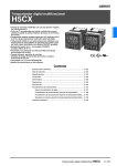
MPC8xx SDRAM Interface
Freescale Semiconductor, Inc...
Heinz Wrobel
Freescale GmbH,
Munich
Janet Snyder
NCSD Applications,
Austin
Part I Introduction
In the long term, Synchronous DRAMs (SDRAM) offer system designers at least two
advantages over conventional Fast Page Mode or EDO DRAMs: a speed-upgrade and density
road map to meet performance requirements of future processors, and a smooth transition to
higher bus speeds without the need to implement major system re-designs. As SDRAMs reach
price parity with conventional memories, SDRAM is making inroads into the PC main
memory, space previously held by EDO/BEDO. This has implications for the embedded
market place. Not only the performance, but also the price reductions will persuade designers
to use SDRAM in preference to the previous architecture. This design concept discusses the
basis of SDRAM operation, and goes on to illustrate a method of interfacing SDRAM to the
MPC8xx. After describing the general procedure to interface SDRAM and the issues, a real
life setup similar to the one used on the Freescale 860 FADS board is presented.
The examples generally assume a 50 Mhz version of the MPC8xx and mention the 40 Mhz
Version and the 66 Mhz Version (with half speed 33 Mhz bus) if appropriate. While specific
SDRAM types from various vendors are referenced in the examples, the JEDEC Standard for
SDRAM (No. 21-C 3.11.5) and Intel’s PC SDRAM Specification (V1.51 11/97) are also taken
into account as influential documents. Based on this information, general usage of arbitrary
SDRAM types should be possible.
1.1
Document Conventions
Due to the different bit numbering scheme for an SDRAM and the PowerPC architecture,
address and data bits are labeled with the subscripts “SD” and “MPC” respectively. In the
32-bit definition of the PowerPC architecture, bit 0 is the most-significant bit, and bit 31 is the
least significant. The standard for RAMs, ROMs, etc., is that the msb is labeled as the highest
number, i.e., 31 or 15, and the lsb is labeled 0. The notation “x:y” is used in places to denote
bits numbered “x” to “y” in that order. References to the User’s Manual refer to the
MPC860UM/AD Rev. 1. Binary numbers have a “0b” prefix. Hex values have a “0x” prefix.
© Freescale Semiconductor, Inc., 2004. All rights reserved.
For More Information On This Product,
Go to: www.freescale.com
Freescale Semiconductor, Inc.
Basics
Part II SDRAM Hardware Interfacing
2.1
Basics
Freescale Semiconductor, Inc...
SDRAMs contain the core of a standard DRAM. The difference is the addition of a clock-gating pin that
synchronizes all inputs and outputs (address, data and control signals) to a single system clock. This makes
the control interface simpler and eliminates the need to generate asynchronous RAS and CAS strobes as
required by conventional DRAMs.
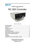
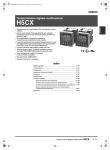
An SDRAM’s memory array is divided into two or more banks (See Figure 1 for a Micron
MT48LC2M8A1-8B SDRAM as example). This allows one bank to be precharged while the other is being
accessed; a process known as interleaving. This process eliminates precharge latency, which in turn
increases bandwidth. When interfacing to the MPC8xx this feature cannot be used when controlling the
memories via the User Programmable Machine (UPM), as it does not support interleaving. Therefore, when
using the UPM any access cycles are treated as individual cycles and the two banks are mapped sequentially
in memory, i.e., bank one sits directly after bank zero in the memory map. The latter is achieved for the
SDRAM used in the example by connecting A9MPC to Bank Select (BSSD) to act as high order address input
to the SDRAM.
Each SDRAM incorporates a burst counter used to increment column addresses on each clock for burst
cycles. The burst length and burst type (sequential or interleaved) is selected by programming an on-chip
mode register. The length of the burst sequence may be set by the user and is programmed for 1, 2, 4, or 8
transfers within a mode register of the SDRAM. The burst sequence takes advantage of a 3 stage pipeline
which allows new memory accesses to be initiated before the preceding access has been completed. When
the pipeline is full, data can be accessed on every clock cycle. After a read burst is completed, the outputs
are tri-stated until a new access cycle is initiated. On the MPC8xx, interleaving is not supported and the total
burst length is always 16 bytes. This means that a sequential burst of four transfers should be programmed
for a 32 bit bus width.
The internal SDRAM mode register settings are also used to determine when to present data-out information
during a read burst. Data may be programmed to appear 1, 2, or 3 clock cycles after a read command. This
feature, which is called CAS latency, allows the system designer to delay the appearance of data onto the
bus until the system is ready for it. No latencies exist for subsequent cycles in a burst read cycle. Please
consult appropriate SDRAM data sheets and specifications for more information about SDRAMs and
especially about the specific device you are investigating. While a common CAS latency is 2, it may vary
depending on the device and speed your are considering in your design.
2
MPC8xx SDRAM Interface
For More Information On This Product,
Go to: www.freescale.com
Freescale Semiconductor, Inc.
Important SDRAM Timings
CLK
Clock
Buffer
Column Decoder
BANK 0
CKE
2048 x 512 x 8
CS
Command
Decoder
RAS
Control
Signal
Generator
Sense Amplifier
Freescale Semiconductor, Inc...
CAS
WE
Data Control
& Buffer
DQ0-7
Mode
Register
A10
DQM
Sense Amplifier
Address
Buffer
A0-A9
BS
BANK 1
Refresh
Counter
2048 x 512 x 8
Column
Counter
Column Decoder
Figure 1. SDRAM Chip Architecture
2.2
Important SDRAM Timings
While SDRAM command information and data are always clocked in with the SDRAM CLK line, there are
certain important timings that must be adhered to for SDRAM to function correctly. Those of special interest
in this document are listed below. The example values are taken from the data sheet of a Micron
MT48LC2M8A1-8B 83 Mhz device. Similar values can be found for other SDRAM devices. The values are
also used to illustrate timing issues with the MPC8xx Memory Controller. Note well that tRCD can also be
specified in clocks with a minimum of 2 for many SDRAM devices. So intentionally a CAS latency of two
clocks is used in all diagrams. The issues are mentioned appropriately. You will usually have to decide
between using safe cycles that work for many SDRAM types or improved cycles that are tweaked to the
timing of a specific SDRAM device in use. There is no general timing that will be best in all cases.
Timing
Micron SDRAM Value
Description
tRCD
20 ns
ACTIVE to READ or WRITE delay
tRP
24 ns
PRCG command period
Table 1. SDRAM Timings
MPC8xx SDRAM Interface
For More Information On This Product,
Go to: www.freescale.com
3
Freescale Semiconductor, Inc.
Hardware Interface
Timing
Micron SDRAM Value
Description
tRC
80 ns
Minimum refresh interval
tCAS
2 clocks
CAS latency. Depends on CLK frequency
tSETUP
2 ns
Common name for worst case signal setup times
to rising edge of CLK
tRSC
2 clocks
Mode Register Set Cycle Time
Table 1. SDRAM Timings
Freescale Semiconductor, Inc...
2.3
Hardware Interface
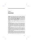
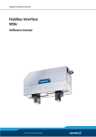
The suggested interface between an MPC8xx and an SDRAM is illustrated in Figure 2. It is clear that this
is a glueless interface. For a 32 bit bus, four eight bit SDRAM devices are connected in parallel. The control
is driven by the UPM on the MPC8xx, so the CS on the SDRAM is interfaced to CS1 on the MPC8xx. Any
other chip select line excluding CS0 would do. The DQM signals of the used SDRAM devices select byte
lanes and are connected to the appropriate Byte Strobe (BS0:3) signals on the MPC8xx. A10SD is connected
to GPL0, since this has the functionality to either drive an address on the line, or a defined level. This is
required as A10SD acts as both an address line and a control line. RAS and CAS are generated by GPL1 and
GPL2 respectively. The WE is generated by GPL3. CLK is driven by the MPC8xx’s CLKOUT signal which
is a reference point with respect to the MPC8xx’s Memory Controller.
As the SDRAM used in the example has 2048 rows and 512 columns, we have to use 11 row address lines
and 9 column address lines. The BS line is connected to line A9MPC and is used as high order address bit.
Please remember that the MPC8xx address lines have a different numbering scheme than the SDRAM
address lines when reading the address line mapping for 32 bit in Table 2.
MPC8xx
SDRAM
A9MPC
BS (Most significant address bit)
A10:20MPC
11 bits to cover 2048 rows
A21:29MPC
9 bits to cover 512 columns
Table 2. SDRAM Address Mapping
Via the UPM Register AMx = 0b001, the address bits A10:20MPC are mapped to lines A19:29 MPC as row
addresses. As we start with line A20MPC to connect to A9SD, we need to provide the left over row address
A10SDnot by using line A19MPC (which would show A10MPC as multiplexed row address), but by using
GPL0 as described above. In the UPM Register MxMR, we program GPL0 to show A10MPC to complete
row addressing.
4
MPC8xx SDRAM Interface
For More Information On This Product,
Go to: www.freescale.com
Freescale Semiconductor, Inc.
Multiple SDRAM Banks
MPC8xx
MT48LC2M8A1-8B * 4
CLKOUT
+5V
CLK
Freescale Semiconductor, Inc...
CKE
CS1
CS
GPL1
RAS
GPL2
CAS
GPL3
WE
GPL0
A10SD
A20:29MPC
A9:0SD
A9MPC
BS
BS1,3
DQM0,2
BS0,2
DQM3,1
D0:31MPC
DQ31:0SD (4 * 8 bits)
Figure 2. SDRAM to MPC8xx Interface
2.4
Multiple SDRAM Banks
Sometimes, a single 32 bit SDRAM bank is not enough memory for an application. Connecting multiple 32
bit SDRAM based banks to the MPC8xx is fairly straightforward.
If the used SDRAM chips support multiple bank select lines, extending the interface described above is easy.
Above, the most significant row address bit is connected to BSSD. A9MPC is used due to the address size of
20 bits (9/11 address multiplex!) covered by the example SDRAM device. For an SDRAM device with two
BS lines, BS0SD and BS1SD, you would simply use the next address bit, e.g., A8MPC, with more significance
to keep the memory mapping linear. In essence, you use address lines for the binary encoding of the bank
selection.
If you have two physical sets or banks of 32 bit SDRAM, you would connect them in parallel but use a chip
select line each. These chip select lines can then be mapped to the same UPM. Please note that you have to
adapt the refresh counter settings for the UPM appropriately. The UPM references all connected chip selects
sequentially. So if you use, e.g., two CS lines for two banks rather than one for a single bank on a single
UPM, you have to double the frequency for the UPM Periodic Timer to keep refresh intervals for the
individual CS line the same.
MPC8xx SDRAM Interface
For More Information On This Product,
Go to: www.freescale.com
5
Freescale Semiconductor, Inc.
SDRAM Commands
Part III SDRAM Usage
3.1
SDRAM Commands
The SDRAM commands used with MPC8xx are summarized in Table 3. They have the following meaning
and restrictions:
ACTIV: Bank Activate Command. Row addresses are latched on A0 SD to A10SD. A further command may
not be issued until tRCD has been met.
Freescale Semiconductor, Inc...
PRCG: Precharge All Command. Precharges both banks simultaneously, and then switches to the idle
state. A further command may not be issued until tRP has been met.
WRITE: Write Command. The write command performs a write access to the bank selected by BSSD (Bank
Select). The data is latched on the positive edge of CLK. The burst length and the addressing mode
are programmed in the Mode Register at power-up prior to the write operation.
Command
A0-9SD
A10S
CS
RAS
CAS
WE
D
ACTV
V
V
L
L
H
H
PRCG
X
H
L
L
H
L
WRITE
V
L
L
H
L
L
WRITEA
V
H
L
H
L
L
READ
V
L
L
H
L
H
READA
V
H
L
H
L
H
MRS
V
V
L
L
L
L
NOP
X
X
L
H
H
H
REF
X
X
L
L
L
H
Table 3. SDRAM Command Structure
WRITEA: Write with Autoprecharge Command. Performs a write command with a precharge operation
automatically after the write operation. This command cannot be interrupted by any other command. A
further command may not be issued until tRP has been met.
READ: Read Command. The read command performs a read access to the bank selected by BS (Bank
Select). The data is issued on the positive edge of CLK, at a time defined by tCAS, the CAS latency.
READA: Read with Autoprecharge Command. Performs a read command with a precharge operation
automatically after the write operation. This command cannot be interrupted by any other command. A
further command may not be issued until tRP has been met.
6
MPC8xx SDRAM Interface
For More Information On This Product,
Go to: www.freescale.com
Freescale Semiconductor, Inc.
SDRAM Access Cycles
MRS: Mode Register Set Command. The MRS command programs the CAS latency, addressing mode,
and burst length in the mode register. This must be configured after power-up as after reset the Mode
Register is undefined. A further command can not be issued until tRSC is met.
NOP: No-Operation. The No-Operation command simply performs no operation (the same as Device
Deselect).
REF: Autorefresh Command. The autorefresh command is used to refresh the row address provided by the
internal refresh counter. This is equivalent to a CAS before RAS refresh on a conventional DRAM. A
further command can not be issued until tRC is met.
Freescale Semiconductor, Inc...
3.2
SDRAM Access Cycles
Below, the different access cycles will be described in detail with timings. Wait clocks can be implemented
as NOP clocks or device deselect clocks. Note that for most cycles an extra timing is suggested for 50 Mhz
bus speed. This is sometimes needed. The reasoning for this will be described in section IV.
3.3
Initialization
The first task with SDRAM is to program the power-up sequence. The JEDEC standard for power-up is the
following:
1)
maintain NOP inputs for 200 µs - the may be maintained after power-up by driving an
inactive state on the memory controller signals.
2)
Issue Precharge command to both banks (PRCG), and wait tRP, the precharge time. For
tRP=24 ns, one wait clock (NOP) is required for 50 Mhz bus speed.
3)
Issue eight auto refresh commands (REF). Between refreshes, the refresh command
period tRC must be met. Based on a tRC value of 80 ns, this requires two wait clocks for
33 Mhz, three wait clocks for 40 MHz, and four wait clocks for 50 Mhz.
4)
Issue a mode register set (MRS) to initialize the mode register. This programs the burst
length, CAS latency and write mode. After time tRSC the first access can occur. For
tRSC = 2 clocks, one trailing wait clock is required.
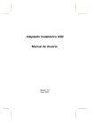
The pattern illustrated below may be driven by the UPM via the appropriate programming. This complete
start-up operation should be programmed into the UPM after start-up to configure the SDRAM correctly.
The actual cycle is shown in Figure 3. Note that the refresh portion of the initialization may also be executed
by simply waiting the required time after initialization for 8 refresh cycles. A loop in the UPM pattern to
generate 8 refresh cycles is more efficient.
An MRS command is initiated by driving CS, RAS, CAS and WE low on the rising edge of the clock. At
this point the address is sampled and its value written into the Mode Register. Note that the next command
cannot be given to the memory until tRSC has elapsed. Note that JEDEC recommends two wait clocks before
the next command.
MPC8xx SDRAM Interface
For More Information On This Product,
Go to: www.freescale.com
7
Freescale Semiconductor, Inc.
Mode Register Settings
200 µs
tRP
tRC
tRSC
Clock
CMD
Freescale Semiconductor, Inc...
ADDR
NOP
PRCG
REF
x8
REF
VALID
MRS
ACTV
CODE
VALID
Note: Required wait clocks are not shown completely due to limited space. Observe timing specifications!
Figure 3. Power-on Initialization
3.4
Mode Register Settings
The following settings in the mode register are required:
Burst Length (A2:0SD) - The burst length can be initialized to 2, 4, or 8 words. As this design is
implemented using a 32-bit wide port, the burst length should be set to 4. With a 32-bit wide port, the
UPM needs to do four accesses in a burst to handle the normal burst size of 16 bytes. Therefore A2:0SD
must be 0b010 during the Mode Register Set (MRS) command.
Address Mode Select (A3SD) - This selects between Interleave mode and Sequential Mode. As the
MPC860 has no support for interleaved memories, Sequential Mode is selected. This requires
A3SD = 0 during the MRS command. Note that the SDRAM’s BS SD (Bank Select) line is connected to
the highest order address line from the MPC860 so that the two SDRAM banks are mapped
sequentially in memory.
CAS Latency (A6:4 SD) - The CAS latency is the number of clocks from the Read command to data valid.
Now, this depends on two factors, the system clock frequency and the speed of part used. For for a
100 MHz part interfacing to a 40 MHz or 50 Mhz bus this should be 2. A6:4SD would be set to 0b010
during the MRS command. With a 33 Mhz bus, a CAS latency of 1 is ok, so 0b001 on A6:4SD would be
the corresponding value. Note that a CAS latency of 1 may not be supported by every SDRAM device.
You may always have to use a CAS latency of 2, depending on the SDRAM device.
Write Mode (A9 SD) - Write mode should be configured for Burst read and Burst write, so A9SD is set to 0
during the MSR command.
All remaining address bits should be set to zero. The total address value required on the SDRAM address
lines is therefore, e.g., 0b100010 or 0x22 for 50 MHz. As the MPC860 is connected with a 32 bit bus, the
actual value is shifted by two bits on the MPC860 address bus, resulting in a value of 0x88 to be used for a
50 MHz design.
8
MPC8xx SDRAM Interface
For More Information On This Product,
Go to: www.freescale.com
Freescale Semiconductor, Inc.
Single Write Cycle
3.5
Single Write Cycle
Freescale Semiconductor, Inc...
Each write cycle is activated with an ACTV command. The SDRAM requires a delay of tRCD from the
ACTV command to the next command, WRITE. The reason that a WRITE command is used instead of a
WRITEA command is because the cycle is required to terminate after one access. For a clock of 50 MHz
the period is 20 ns, so the next command may not be given on the next clock due to lack of any margin. A
wait clock can be found in Figure 4 because of tRAS with 40 MHz. The write is terminated with a PRCG
command after another dummy cycle for 50 MHz. As tRAS is 50 ns, we need to add wait clocks again for
higher bus speeds than 33 MHz. The next ACTV command may not be driven until tRP is met. As this is
24 ns, an extra cycle must be added to the end of the access for 50 MHz. This results in a complete best case
access time of 3 clocks for 33 Mhz, 4 clocks for 40 MHz, and 5 clocks for 50 Mhz. The clock count for
50 Mhz takes UPM behavior as described in section IV into account for the best case value. Figure 4 shows
the general approach, with a wait clock either in the front or in the back of the cycle.
The DQM signal is shown in Figure 4 once for reference purposes only. It has to be set appropriately for
any type of data access cycle and will be omitted in subsequent diagrams.
Clock
tRCD = 20 ns
Command
ACTV
tRP = 24 ns
Note 1
WRITE
PRCG
tRAS = 50 ns
ADDR
COLUMN
ROW
DATA
DATA-1
DQM
Note 1: Not really needed for this tRCD, but for tRAS at 40 Mhz.
Figure 4. Single Write Cycle (33 MHz and 40 Mhz)
Clock
tRP = 24 ns
tRCD = 20 ns
Command
Note 1
WRITE
ACTV
PRCG
Note 1
tRAS = 50 ns
ADDR
ROW
DATA
COLUMN
DATA-1
Note 1: See section on UPM Issues for 50 MHz.
Figure 5. Single Write Cycle (50 Mhz)
MPC8xx SDRAM Interface
For More Information On This Product,
Go to: www.freescale.com
9
Freescale Semiconductor, Inc.
Single Read Cycle
3.6
Single Read Cycle
Freescale Semiconductor, Inc...
Each read cycle is activated with a ACTV command. The SDRAM requires a delay of tRCD from the ACTV
command to the next command READ. The reason that a READ command is used instead of a READA
command is because it is required to terminate the cycle after one read. The next command must wait tRCD
before being issued. The read is terminated with a PRCG command. The next ACTV command may not be
driven until tRP is met. As this is 24 ns, an extra cycle must be added into the access for 50 MHz. This results
in a complete best case access time of 4 clocks for 33 MHz and 5 clocks for 40 MHz. Note that the total
cycle length doesn’t change when removing the wait clock after ACTV because of tRAS. As shown in
Figure 7, a 50 Mhz access looks fairly similar and can also have a best case access time of 5 clocks.
Clock
tRP = 24ns
tRCD = 20ns
Command
ACTV
Note 1
READ
PRCG
tRAS = 50 ns
ADDR
ROW
COLUMN
tCAS
DATA
DATA-1
Note 1: Not really needed for this tRCD, but for tRAS at 40 Mhz.
Figure 6. Single Read Cycle (33 MHz and 40 MHz)
Clock
tRP = 24 ns
tRCD = 20 ns
Command
Note 1
ACTV
READ
PRCG
Note 2
tRAS = 50 ns
ADDR
ROW
COLUMN
tCAS
DATA
DATA-1
Note 1: See section on UPM Issues for 50 MHz.
Note 2: Needed, but conveniently overlaps with DATA-1. No extra clock required.
Figure 7. Single Read Cycle (50 MHz)
10
MPC8xx SDRAM Interface
For More Information On This Product,
Go to: www.freescale.com
Freescale Semiconductor, Inc.
Burst Write Cycle
3.7
Burst Write Cycle
Each write cycle is activated with an ACTV command. The SDRAM requires a delay of tRCD from the
ACTV command to the next command WRITEA. For the burst cycle a WRITEA, write with precharge, is
used. This will execute a 4 beat write, starting on the rising edge of this cycle. The data is then sampled on
this and the next three rising clock edges. It will also execute a automatic precharge cycle at the end of the
access. This access will be after the final data write. The next ACTV command may not be driven until tRP
is met. As this is 24 ns, an extra cycle must be added into the access for 50 MHz. This results in a complete
best case access time of 6 clocks for a 33 Mhz or 40 MHz bus (2/1/1/1/+1). A 50 Mhz bus requires 8 clocks
as can be seen in Figure 9, using a (4/1/1/1/+1) cycle.
Freescale Semiconductor, Inc...
Clock
tRP = 24 ns
tRCD = 20 ns
Command
ACTV
ADDR
ROW
WRITEA
Note 1
AP
COL
DATA-1 DATA-2 DATA-3 DATA - 4
DATA
Note 1: Not really needed for this tRCD. May be needed for slower devices.
Figure 8. Burst Write Cycle (33 Mhz and 40 MHz)
Clock
tRP = 24 ns
tRCD = 20 ns
Command
ADDR
DATA
Note 1
ACTV
WRITEA
ROW
COL
AP
Note 1
DATA-1 DATA-2 DATA-3 DATA - 4
Note 1: See section on UPM Issues for 50 MHz.
Figure 9. Burst Write Cycle (50 MHz)
MPC8xx SDRAM Interface
For More Information On This Product,
Go to: www.freescale.com
11
Freescale Semiconductor, Inc.
Burst Read Cycle
3.8
Burst Read Cycle
Freescale Semiconductor, Inc...
Each read cycle is activated with a ACTV command. The SDRAM requires a delay of tRCD from the ACTV
command to the next command READA.For the burst cycle a READA, read with precharge, is used. This
will execute a four beat read, starting on the rising edge of the next cycle. The data is then presented on the
next four rising clock edges. It will also execute an automatic precharge cycle at the end of the access. This
access is simultaneous to the final data read. The next ACTV command may not be driven until tRP is met.
As this is only 24 ns, no extra cycle must be added into the access due to the overlap with the data transfer.
This results in a complete best case access time of 7 clocks for a 33 MHz or 40 MHz bus (4/1/1/1). For
50 Mhz, a different timing is needed, resulting in 8 clocks best case total access time (5/1/1/1), depending
on the 860 chip revision. See section IV for more information.
Clock
tRCD = 20 ns
Command
ACTV
ADDR
ROW
Note 1
tRP = 24 ns
tCAS = 2 clocks
AP
READA
COL
DATA
DATA-1
DATA-2
DATA-3
DATA - 4
Note 1: Not really needed for this tRCD. May be needed for slower devices.
Figure 10. Burst Read Cycle (33 Mhz and 40 MHz)
Clock
tRCD = 20 ns
Command
ADDR
DATA
Note 1
ACTV
READA
ROW
COL
AP
Note 2
DATA-1 DATA-2 DATA-3 DATA-4
Note 1: See section on UPM Issues for 50 MHz.
Note 2: Needed, but conveniently overlaps with DATA-4. No extra clock required.
Figure 11. Burst Read Cycle (50 MHz)
12
tRP = 24 ns
tCAS = 2 clocks
MPC8xx SDRAM Interface
For More Information On This Product,
Go to: www.freescale.com
Freescale Semiconductor, Inc.
Refresh Cycle
3.9
Refresh Cycle
A refresh access is shown in Figure 12 for a 33 MHz and 40 Mhz bus. This is initiated by the UPM’s refresh
counter, and executed as defined in the UPM table by a auto refresh command. Note that t RC must be met.
This is 80 ns. Therefore for a 33 MHz bus, 2 wait clocks are required before the next command while
40 MHz needs one additional wait clock. For a 33 Mhz you need three, for 40 MHz four, and for a 50 Mhz
bus five total clocks for a best case timing. Note that Figure 13 tries to illustrate the general case.
Clock
Freescale Semiconductor, Inc...
tRC
REF
CMD
Command
Note 1
ADDR
Note 1: Needed for 40 MHz.
Figure 12. Refresh Cycle (33 Mhz and 40 Mhz)
Clock
tRC
CMD
REF
Note 1
Command
Notes 1,2
ADDR
Note 1: See section on UPM Issues for 50 MHz.
Note 2: Any other 50 MHz cycle may start with a wait cycle, too. So tRC is met.
Figure 13. Refresh Cycle (50 Mhz)
3.10 Estimated Performance
Table 4 shows the estimated performance in CPU clocks when using SDRAM with an MPC8xx. Note that
the bus clock is mentioned, not the CPU clock. The access times calculated include provision for precharge.
Note that the better timings are listed for 50 MHz. This depends on the 860 chip revision as outlined in
section IV. Also note that the implicit wait clock as outlined in section 4.1 is not included in the listed access
times. Be careful when adapting these values to the real world.
CLKOUT
Single Read
Single Write
Burst Read
Burst Write
33 MHz
4 (120 ns)
3 (90 ns)
7 (210 ns)
6 (180 ns)1
3 (90 ns)
40 MHz
5 (125 ns)
4 (100 ns)
7 (175 ns)
6 (150 ns)1
4 (100 ns)
MPC8xx SDRAM Interface
For More Information On This Product,
Go to: www.freescale.com
Refresh
13
Freescale Semiconductor, Inc.
Wait clocks and back to back cycles
CLKOUT
50 MHz
Single Read
Single Write
5 (100 ns)
5 (100 ns)1
Burst Read
8 (160 ns)
Burst Write
8 (160 ns)1
Refresh
5 (100 ns)
Table 4. SDRAM Performance
1:
These cycle times could be improved by one clock if the actual design allows to take the implicit wait clock (See
section 4.1) into account for precharge purposes.
Freescale Semiconductor, Inc...
Part IV UPM Issues
This document tries to describe SDRAM interfacing for different bus speeds. This led to the different
timings shown above and various possibilities for variations with respect to UPM patterns, depending on the
SDRAM device used and your goals for interfacing. Leaving aside timing specifications of SDRAM, there
are two basic issues, wait clocks and 50 MHz bus speed, that should be understood well, when setting up
UPM RAM words.
4.1
Wait clocks and back to back cycles
Each SDRAM access needs to finish with precharged banks because of not having bank or interleaving
support as explained in section 2.1. The precharge time, e.g., tRP=24 ns needs to be taken into account
before the next UPM pattern can be run, which translates into one wait clock until the next command for
50 MHz. UPM behavior helps in avoiding that wait clock in the patterns. Note that after processing the last
UPM RAM word of a pattern, there is one implicit “wait” clock before the first word of the next pattern can
be started. This implicit clock appears due to the setup work like early GPL5 setting or SAM support via
ORx registers before the first UPM word of the next pattern is run. In effect this means that UPM RAM
words of two patterns never execute fully back to back. There is always at least one “inactive” clock in
between when a new UPM access is started. In our application this means that we can use this implicit wait
clock to take care of precharge requirements in our UPM patterns. It also means that this implicit and
unavoidable wait clock will appear in our access clock count, even though it may not really be necessary for
some cycles.
4.2
Using 50 Mhz Bus Speed
For bus speeds of less than 50 Mhz, the SDRAM cycles described above can be converted into UPM patterns
directly.
Note:
For 50 Mhz bus speed, the conversion of the timing diagrams into UPM patterns depends on the
860 chip revision that you intend to use. UPM timing specifications B3x have been improved for
MPC860 Rev B.1 silicon starting at date code 9829 or later. Rev B.1 silicon with date code 9829
and newer has a maximum B3x specification of 6 ns rather than 8 ns. For the 860T, the date code
is 9840 or later. This is currently not the case for all MPC850’s where improved timings have not
yet been specified.
For earlier chips without the improved timing specification, an additional trick needs to be used, resulting
in the net performance described in Table 4 and the slightly different figures used to describe the cycles. All
SDRAM commands are clocked in by the SDRAM with the rising edge of CLKOUT. The setup time
tSETUP=2 ns in this example has to be met. The UPM puts out timings relative to the falling edge of
14
MPC8xx SDRAM Interface
For More Information On This Product,
Go to: www.freescale.com
Freescale Semiconductor, Inc.
Hardware Issues
Freescale Semiconductor, Inc...
CLKOUT as described in chapter 16 of the MPC860 User’s Manual. The maximum time for the relevant
signals in the UPM cycles is specified as8 ns for a 50 MHz MPC8xx without the improved specification.
This means that the setup time for the SDRAM signals can’t be met within the 10 ns available in half a clock
cycle as no margin is left for signal propagation. The result is that the actual UPM timing for each access
cannot to be started in the first UPM entry (named CST4 or GxT4 in the User’s Manual for the MPC860 in
Figure 16-36) for any UPM cycle. The solution is to add an initial, mostly idle, dummy clock and use the
last of the four UPM slots (CST3 and GxT3) within that dummy clock cycle to set up the SDRAM signals
for the following rising edge of CLKOUT. The same early setup should be done for all the following clocks
to meet the setup times in every clock of a UPM pattern. The UPM RAM words have to be set up
appropriately.
Obviously this alone would add one full dead clock cycle to any SDRAM access. As any SDRAM access
has to finish with a precharge/refresh command and at least one wait clock for a 50 MHz bus, we can shave
off one wait clock at the end of some UPM cycles for the one that we have to add in the front. This way, the
refresh and precharge times tRC and tRP will still be met, as the UPM cycles are basically “rotated” 0.75
clock cycles to the right.
For Rev B.1 silicon or better as described above the situation is easier. Here, rotating the pattern as described
above is not necessary because of the 2 ns margin left with respect to tSETUP=2 ns of the example SDRAM.
Part V Design Variations and Caveat’s
5.1
Hardware Issues
Obviously, this design concept does not present the only possible way to implement an SDRAM design. The
MPC860 SAMBA reference design and the FADS board introduce small variations due to the different
SDRAM device type used. The address mapping is slightly different as can be seen by the use of A10MPC
for A11SD (which is essentially equivalent to BSSD as used in this document). It would also be permissible
to shuffle around use of GPL1 to GPL3, as these lines are functionally interchangeable or use any chip select
line except for CS0.
5.2
Address and Data Line Mapping
An issue to be aware of is address and data line mapping. Historically, it has been possible to fairly
arbitrarily shuffle around address or data lines to facilitate PCB layout or obfuscate designs with DRAM’s
or SRAMs. This is no longer easily possible for address lines on SDRAM devices. As the address lines are
used to convey configuration information to the SDRAM device, care should be taken to create a normal
mapping that is not arbitrarily changed during PCB layout. Note again that PowerPC bit numbering is
different from SDRAM bit numbering. Take special care when mapping data and address lines.
5.3
Address Multiplexing Options
Address multiplexing tends to be a hot topic, too. This is due to the variety of available SDRAM devices
and the abundance of MPC8xx options to control address multiplexing. One issue here that leads to
confusion is how to make the decision if an address pin needs to be multiplexed or not. As the lower order
address pins are connected to the SDRAM device, the “natural” connection is for the column address. The
multiplexed address is the row address. For an SDRAM device, the row address uses typically more
significant bits than the column address. This means that the high order address bits on the SDRAM device
MPC8xx SDRAM Interface
For More Information On This Product,
Go to: www.freescale.com
15
Freescale Semiconductor, Inc.
SDRAM technology
Freescale Semiconductor, Inc...
that are not used for column addressing can be connected either via the multiplex scheme or directly. Two
different methods of connecting address lines lead to identical results here. Consider, e.g., a 12/8
row/column mapping for a 32 bit bus. As in the 860 FADS schematics, A29-A18MPC can be used for the
address lines A0-11SD. With an AMx value of 0b000, A11SD (connected directly to A18MPC) is multiplexed
to A10MPC for row addressing as expected. The same is respectively valid for the other address lines. Now
consider that A8-11SD are never used for column addressing here. Basically this means that you don’t really
have to connect these lines via the AMx mechanism, given the environment of this example. You could
directly interface them to A13-10MPC without any functional change. This illustrates an issue that could be
considered philosophical, unless, e.g., routing issues make it practical. If AMx multiplexing needs to be
used, it could on one hand be used for all address lines that it covers for consistency reasons. On the other
hand, it could be argued that row addresses not in need of column multiplexing should be connected directly
to avoid ambiguity issues. The 860 FADS design actually implements both schemes. A11SD is connected
directly to A10MPC, while the remaining lines are connected based on AMx multiplexing.
5.4
SDRAM technology
SDRAM technology is evolving, too. Setup times for signals tend to get reduced, and, eventually, timing
may well be tightened even more for some devices, saving clock cycles in access time. Recently ESDRAM
appeared on the market. Due to internal improvements, read accesses can usually be shortened by one clock
compared to normal SDRAM devices. Keeping advancements like these in mind, it is well worth
investigating multiple vendors before deciding on a high performance SDRAM device that fits the
application well. Also, you should consider if you set up UPM patterns specifically for a certain SDRAM
device or make them general enough to work with various SDRAM timings as specified by multiple
vendors.
5.5
Timing Issues
Last but not least, you should never forget timing issues. The described timings do not take any buffering
into account. If you intend to use SDRAM modules requiring buffering in your design. You may have to
check every single suggested timing to take buffering into account. Don’t forget that buffering for address
and data lines and buffering for the clock may behave differently. When deciding on buffers, don’t forget to
check load capacitance values for the devices used. Often it is best for system performance to connect the
SDRAM unbuffered and, as appropriate, buffer the rest of the system. Clock jitter, skew, and trace delays
may also affect your timing. If in doubt, start out with a safe pattern. Premature optimization is the root of
all evil, Donald E. Knuth once said.
Part VI SDRAM on the MPC8xx FADS Board
This section will illustrate an actual implementation of an SDRAM interface to the MPC8xx family,
including register settings and some basic UPM patterns. It steps through the system design for using two
100Mhz SDRAMs in an MPC8XX system with a bus speed of 50Mhz, utilizing the MPC8XX’s Memory
Controller’s User Programmable Machine B (UPMB): the Hardware Interface, System Specifications, and
SDRAM Initialization. This is intended as a procedural guideline only, and is not optimized for system
performance. You will notice that once again different SDRAM types are shown to illustrate this example.
Note:
16
The cycles and UPM patterns presented here rely on being used with an MPC860 of at least Rev
B.1 with date code 9829 or later, except for the MPC860T where the date code is 9840 or later, see
section 4.2.
MPC8xx SDRAM Interface
For More Information On This Product,
Go to: www.freescale.com
Freescale Semiconductor, Inc.
The assumed SDRAM hardware
6.1
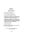
The assumed SDRAM hardware
This example system, comparable to both the Freescale MPC8XX Family Application Development System
(FADS) and the MPC860T SAMBA Reference Design, uses two JEDEC standard SDRAMs that are 2 x
512 x 16. Examples of these SDRAMs are the Fujitsu MB811171622A and the Samsung KM416S1020B.
They are configured in this system as 2 X 512K X 32, providing a total of 4 MBytes. See Figure 14 for
details.
Freescale Semiconductor, Inc...
CS4
GPL1
GPL2
GPL3
A10MPC
GPL0 (A11MPC)
A20:21MPC
A22:29MPC
Pull-up to 3.3V
SYSCLK
CS
CS
RAS
RAS
CAS
CAS
WE
WE
A11SD
A11SD
A10SD
A10SD
A9:8SD
A9:8SD
A7:0SD
A7:0SD
CKE
CKE
CLK
CLK
BS0_B
DQMU
DQMU
BS1_B
DQML
DQML
DQ15:0SD
DQ15:0SD
D0:15MPC
BS2_B
BS3_B
D16:31MPC
Figure 14. Example Hardware Interface
Note that in this example, the SDRAM is unbuffered from the processor, saving the delay associated with
address and data buffers. This is an optimal design from the performance standpoint. Be sure to keep the
loading on the address and data buses within the MPC8XX specification, which is 50 pF. For instance, this
SDRAM has 4 pF on the address lines and 5 pF on the data lines, so with two of these on the buses, there
are 42 pF left for the address lines and 40 pF left for the data lines to accommodate buffers and any other
devices which need a raw address or data line connected.
Although this is mentioned above, it bares repeating here. Do not try and reverse the numbering of the
address and data buses. It is tempting to do so for the sake of being able to think of the numbering in a
MC68360 way, but with SDRAM the risk of error is greater than during a simpler paged-mode DRAM or
EDO DRAM design. With SDRAMs, initialization of various parameters are done via specific address lines,
MPC8xx SDRAM Interface
For More Information On This Product,
Go to: www.freescale.com
17
Freescale Semiconductor, Inc.
SDRAM System Specification
as well as control and, of course, coordination with byte lanes. We will cover this initialization and control
in greater detail later. So, leaving the numbering as-is, an SDRAM's DQ0:15SD correlates to the MPC8XX's
D31:16MPC, and the same goes for the address line scheme.
6.2
SDRAM System Specification
Before beginning programming for the MPC8XX memory controller, two system’s specifications must be
calculated for the SDRAM: the SDRAM performance for each cycle type and the programming needs of
the SDRAM’s Mode Register.
Freescale Semiconductor, Inc...
For this example, theSDRAM’s performance figures for each cycle type, are shown in Table 4 on page 13.
These numbers are used in both initialization and UPM RAM Array programming for designating and
generating these cycle types. The values are based on the given system clock speed and the speed of the
SDRAM, which in this example is 100 Mhz.
The SDRAM’s Mode Register can be likewise charted for ease later in programming. These are values used
during SDRAM initialization which will tailor the SDRAM for various specific system values. Here are the
ones required in an MPC8XX design. Luckily, they can remain the same in our bus frequency range:
SDRAM Option
33 - 50 MHz
Burst Length
4
Burst Type
Sequential
CAS Latency
2
Write Burst Length
Burst
Table 5. SDRAM Mode Register Programming
For an explanation of these values and their mapping to the SDRAM address lines, please refer to
section 3.4. Net result is an address pattern of 0b0100010 on the SDRAM address bus.
Remember that due to the 32 bit access via two SDRAM devices, the required address value will be shifted
left by two bits on the MPC8xx address bus. In our example of a 50 Mhz bus with the 100 Mhz SDRAMs,
the SDRAM’s Mode Register value to be used by the MPC8xx will be 0x88.
6.3
Note:
18
The UPM Patterns
NOTE: RAM Array words used in this example can be used on both the MPC8XX FADS and
MPC860T SAMBA Reference Design. They are not necessarily optimal patterns. They can be used
for verification purposes when implementing your own patterns based on the suggested timings
above.
MPC8xx SDRAM Interface
For More Information On This Product,
Go to: www.freescale.com
Freescale Semiconductor, Inc.
The Initialization Pattern
6.4
The Initialization Pattern
Now we need to find what waveform patterns need to be generated to the SDRAM during initialization to
set it for specifically how it operates within our system. Each SDRAM spec identifies this procedure of
pattern generation. It typically involves the manipulation of CS, CAS and RAS, and W lines. It also uses an
address line; in our example, this is A10SD, which corresponds to A11MPC. For the latter, we set the General
Line 0 Control A (G0CLA) bits to 0b001, which allows A11MPC to fall out through the GPL0 pin.
The patterns needed are generated as UPM RAM Array words, created the same way as RAM Array words
are created to generate a cycle type, such as a Single Read or Single Write. Set the timing chart values
needed in relation with CLKOUT and GCLK1, and calculate the 32-bit RAM Array Words necessary to
generate the pattern. (See the MPC860 User’s Manual, Memory Controller section).
Freescale Semiconductor, Inc...
For our example, the RAM Array words calculated are 0x1FF77C35 and (0xEFCABC34, 0x1F357C35) for
the initial precharge and the mode register set command.
As can be seen in any SDRAM specification sheet, it is programmed by issuing a Mode Register Set
command. This is begun by the MPC8XX by using the Memory Controller’s Memory Address Register
(MAR) to toggle the address lines which we calculated above. And then we use the Memory Controller’s
Memory Command Register (MCR) to execute a run command of the RAM Array words above necessary
for initialization. Note that we use two UPM RAM words to handle the MRS command to be able to set up
the address via MAR in time. Then we execute the appropriate 8 refreshes which signals the end of the
SDRAM’s initialization sequence. Finally, we set the refresh rate to 4 for normal operation as described
below and program the mode register. The choice to do a refresh burst of 4 beats at once is an arbitrary
decision. Depending on your latency needs you may want to, e.g., do single beat refreshes and set up the
refresh timer appropriately in the respective MxMR.
6.5
SDRAM Initialization
Following power-up, the initialization sequence as shown below should be executed. This description
follows the steps in section 3.3 on page 7, but in much greater detail for this specific example.
1)
UPMB should be programmed with values designating Single Read at offset 0x00, then
program the initialization words above into offset 0x05, Burst Read at offset 0x08, Single
Write at offset 0x18, Burst Write at offset 0x20, Refresh at offset 0x30, and Exception at
offset 0x3C.
2)
Program the Memory controller’s MPTPR, MBMR, OR4 and BR4. We are using the
starting address of 0x3000000 - 0x33FFFFF.
3)
Wait the SDRAM start-up delay time of 200 µs before doing any SDRAM access.
4)
Set the MAR to 0x88 for initialisation and the Mode Register Set.
5)
Issue a precharge command for both banks using the pattern in location 0x05.
6)
Set the MCR to 0x80808830 to run the refresh sequence (immediately runs 8 Refresh
cycles).
7)
Set the MCR to 0x80808106 to run the MRS command programmed in locations 0x06
and 0x07 of UPMB.
8)
The SDRAM isrefreshed using its auto-refresh mode. This is accomplished by using the
UPM B’s periodic timer. A burst of four auto-refresh commands is issued to the SDRAM
every 62.4 µs, so that all 2048 SDRAM rows are refreshed within specified 32.8 ms.
9)
The SDRAM is initialized and ready for operation.
MPC8xx SDRAM Interface
For More Information On This Product,
Go to: www.freescale.com
19
Freescale Semiconductor, Inc.
MPC8Bug Programming Example
6.6
MPC8Bug Programming Example
The following example illustrates how to set up SDRAM patterns. Note that the patterns are based on
updated UPM timings as outlined in section IV on page 14.
##################################################################
# SDRAM - Fujitsu MB811171622A-100MHz Initialization Routine
#
# MPC8XX with bus speed of 50Mhz, using a 4Mhz oscillator.
#
# UPM B used as controller
#
##################################################################
{
# Single Read, 50 MHz (offset 0x00 in upm ram)
upm :b 0, 1F07FC04 EEAEFC04 11ADFC04 EFBBBC00 1FF77C47
Freescale Semiconductor, Inc...
# Precharge and MRS, (using free space in UPMB)
upm :b 5, 1FF77C35 CABC34
EF
1F357C35
# Burst Read 50MHz (offset 0x08 in upm ram)
upm :b 8, 1F07FC04 EEAEFC04 10ADFC04 F0AFFC00 F0AFFC00 F1AFFC00 EFBBBC00 1FF77C47
# Single Write, 50 MHz (offset 0x18 in upm ram)
upm :b 18, 1F27FC04 EEAEBC00 01B93C04 1FF77C47
# Burst Write, 50 Mhz (offset 0x20 in upm ram)
upm :b 20, 1F07FC04 EEAEBC00 10AD7C00 F0AFFC00 F0AFFC00 E1BBBC04 1FF77C47
# Refresh, 50 Mhz (offset 0x30 in upm ram)
upm :b 30, 1FF5FC84 FFFFFC04 FFFFFC04 FFFFFC04 FFFFFC84 FFFFFC07
# exception (offset 0x3c in upm ram)
upm :b 3c, 7FFFFC07
# MPTPR (divide by 16)
rms memc mptpr 0400
# machine B mode register SDRAM 32MHz brgclk
rms memc mbmr 80802114
# (D0802114 for 50MHz)
# option register 4 - SDRAM 4 MBytes,
rms memc or4 FFC00A00
# base register 4 - SDRAM @ 3000000 on upm B
rms memc br4 030000C1
# start SDRAM init: (note that required wait timings are not shown)
rms memc mar 88
# MR 88 for high range
rms memc mcr 80808105
# run precharge pattern from loc 5
rms memc mcr 80808830
# run refresh pattern 8 times
rms memc mcr 80808106
# run MRS pattern from loc 6
Part VII Revision History
REV 0.0: Original
REV 0.1: BS now driven by PQ_A8 in Figure. ROW address is made up by PQ_A(9:19) mapped to A(10:0)
on the SDRAM, COLUMN address is made from PQ_A(20:29) mapped to A(9:0). Note that Physical
connection is between PQ_A(20:29) to A(9:0), GPL0 to A10, but programmed to assert PQ_A(9).
20
MPC8xx SDRAM Interface
For More Information On This Product,
Go to: www.freescale.com
Freescale Semiconductor, Inc.
MPC8Bug Programming Example
REV 0.2: BS changed to PQ_A10 in Figure (corrected address multiplexing error).
REV 0.3: (HWG) major rework to include information about different bus speeds and UPM issues.
REV 0.4: (HWG) Clarified ambiguous wording about address usage and wait clocks. Some minor cosmetic
corrections. Clarifications in section IV on page 14. Incorrect timing description in section 3.7 on page 11
fixed.
REV 0.5: (HWG) More text fixes. Added section about design variations. GPL line usage matches the
reference designs now. Binary numbers marked with “0b”.
REV 0.6: (HWG) Date change and revision bump for another release.
REV 0.7: (HWG) Added some technology comments and more explanations.
Freescale Semiconductor, Inc...
REV 0.8: (HWG) Added input from co-authors. Some edits for more current Micron SDRAM.
REV 0.8: (HWG) Major rework to integrate Janet Snyder’s design example with code app note. Took PC
SDRAM specification into account.
REV 0.9: (HWG) Date code fix according to the official timing sheet.
REV 1.0: (HWG) Fixed MRS command. Something got lost in the Cut & Paste phase, *sigh*. MRS needs
to use two UPM RAM words or the addresses won’t be set up in time. The previous single RAM word
pattern most likely worked by accident only. The initial refresh should also be eight beats now. This had not
been noticed before as the common setup times for ADS boards left enough room for normal refresh cycles
to kick in. Also fought with the spell checker one last time.
REV 1.1: (HWG) Some more typos fixed. UM references now mention Rev 1. The cycle count statements
were misleading. The rework lead to single beat writes for 40 MHz now being shown as slower than before
to be in line with the rest of the description.
REV 1.2: (HWG) WIP. Revisited cycle counts again. Now the info should be fairly consistent. Hopefully.
REV 1.3: (HWG) Typo fixes and a note added to the cycle count table. Write timings can possibly be
improved in real designs.
REV 1.4: (HWG) Initialization and MAR handling was not matching in section 6.4 and section 6.6.
REV 1.5: Revised for new documentation template and standards.
MPC8xx SDRAM Interface
For More Information On This Product,
Go to: www.freescale.com
21
Freescale Semiconductor, Inc.
How to Reach Us:
Home Page:
www.freescale.com
E-mail:
[email protected]
Freescale Semiconductor, Inc...
USA/Europe or Locations Not Listed:
Freescale Semiconductor
Technical Information Center, CH370
1300 N. Alma School Road
Chandler, Arizona 85224
+1-800-521-6274 or +1-480-768-2130
[email protected]
Europe, Middle East, and Africa:
Freescale Halbleiter Deutschland GmbH
Technical Information Center
Schatzbogen 7
81829 Muenchen, Germany
+44 1296 380 456 (English)
+46 8 52200080 (English)
+49 89 92103 559 (German)
+33 1 69 35 48 48 (French)
[email protected]
Japan:
Freescale Semiconductor Japan Ltd.
Headquarters
ARCO Tower 15F
1-8-1, Shimo-Meguro, Meguro-ku,
Tokyo 153-0064
Japan
0120 191014 or +81 3 5437 9125
[email protected]
Asia/Pacific:
Freescale Semiconductor Hong Kong Ltd.
Technical Information Center
2 Dai King Street
Tai Po Industrial Estate
Tai Po, N.T., Hong Kong
+800 2666 8080
[email protected]
For Literature Requests Only:
Freescale Semiconductor Literature Distribution Center
P.O. Box 5405
Denver, Colorado 80217
1-800-441-2447 or 303-675-2140
Fax: 303-675-2150
[email protected]
Information in this document is provided solely to enable system and software
implementers to use Freescale Semiconductor products. There are no express or
implied copyright licenses granted hereunder to design or fabricate any integrated
circuits or integrated circuits based on the information in this document.
Freescale Semiconductor reserves the right to make changes without further notice to
any products herein. Freescale Semiconductor makes no warranty, representation or
guarantee regarding the suitability of its products for any particular purpose, nor does
Freescale Semiconductor assume any liability arising out of the application or use of
any product or circuit, and specifically disclaims any and all liability, including without
limitation consequential or incidental damages. “Typical” parameters which may be
provided in Freescale Semiconductor data sheets and/or specifications can and do
vary in different applications and actual performance may vary over time. All operating
parameters, including “Typicals” must be validated for each customer application by
customer’s technical experts. Freescale Semiconductor does not convey any license
under its patent rights nor the rights of others. Freescale Semiconductor products are
not designed, intended, or authorized for use as components in systems intended for
surgical implant into the body, or other applications intended to support or sustain life,
or for any other application in which the failure of the Freescale Semiconductor product
could create a situation where personal injury or death may occur. Should Buyer
purchase or use Freescale Semiconductor products for any such unintended or
unauthorized application, Buyer shall indemnify and hold Freescale Semiconductor
and its officers, employees, subsidiaries, affiliates, and distributors harmless against all
claims, costs, damages, and expenses, and reasonable attorney fees arising out of,
directly or indirectly, any claim of personal injury or death associated with such
unintended or unauthorized use, even if such claim alleges that Freescale
Semiconductor was negligent regarding the design or manufacture of the part.
AN2066/D
For More Information On This Product,
Go to: www.freescale.com