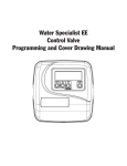
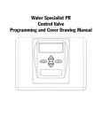
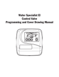
1
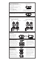
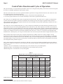
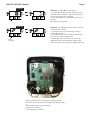
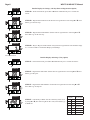
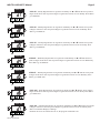
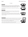
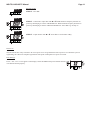
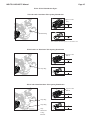
Water Specialist 1” Control Valve Series Model: WS1TC 1.25” Control Valve Series Model: WS1.25TC Operation and Instruction Manual for OEM Only. Please Note: This operation and instruction manual is for the training of the OEM and for the OEM to use to train their customers. This document is not to be used as the complete system manual. MANUAL REGENERATION NOTE: For softeners, if brine tank does not contain salt, fill with salt and wait at least 2 hours before regeneration. If you need to initiate a manual regeneration, either immediately, or tonight at the preprogrammed time (typically 2 a.m.), complete the following steps. For Immediate Regeneration: Press and hold V and W simultaneously until valve motor starts (typically 3 seconds). Arrow will point to Regen if a regeneration is expected “Tonight.” For Regeneration Tonight: Press and release V and W simultaneously (notice that arrow points to Regen). If the display shows “E1,” “E2”, “E3”, or “E4” (for error), call a service technician. To shut off water to the system, please position arrow handles as shown in the bypass operation diagram below. If your valve doesn’t look like the diagram below, contact your service technician for instructions on how to shut off water. NORMAL OPERATION Treated Water Exits BYPASS OPERATION Supply Water Enters Supply Water Exits GENERAL OPERATION Arrow will point to Regen if a regeneration is expected “Tonight.” When the system is operating one of two displays will be shown: time of day or days until the next regeneration. Pressing V or W button will toggle between the two choices. or TO SET TIME OF DAY 1. Accessed by pressing SET for approximately 3 seconds. 2. Adjust hour with Vor W. With 60 Hz line frequency detection on power-up, timekeeping is 12 hour with PM indicator. With 50 Hz line frequency detection on power-up, timekeeping is 24 hour without the PM indicator. Press SET to go to the next step. 3. Adjust minutes with Vor W. 4. Press SET to complete and return to normal operation. In the event of a prolonged power outage, time of day flashes, indicating that it needs to be reset. All other information will be stored in memory no matter how long the power outage. Please complete the steps as shown to the right. To access this mode, press “SET.” TO SET TIME OF REGENERATION AND DAYS BETWEEN REGENERATION For initial set-up or to make adjustments, please complete the steps as shown. Access this mode by pressing SET and V for approximately 3 seconds. The number of days between regenerations may need to be varied based on usage and water conditions. (This step will not appear if the 7-day clock option is selected.) Supply Water Enters 3 sec. 1. Accessed by pressing SET and V simultaneously for about 3 seconds. 2. Set Regeneration Time Hour. Set the time for regeneration to start. Press SET to go to the next step. 3. Set Regeneration Time Minutes. Press SET to go to the next step. 4. Set number of Days between regeneration cycles. 5. Press SET to complete and return to normal operation. Table of Contents Control Valve Function and Cycles of Operation ...........................................................................................................4 OEM General Programming Instructions ........................................................................................................................6 OEM System Setup ...........................................................................................................................................6 Installer Displays/Settings .................................................................................................................................8 User Displays/Settings.....................................................................................................................................10 Drawings and Part Numbers Front Cover and Drive Assembly ....................................................................................................................12 WS1TC Drive Cap, Pistons and Spacer Stack ................................................................................................13 WS1.25TC Drive Cap, Pistons and Spacer Stack ...........................................................................................14 WS1 & WS1.25 Identication Figure .............................................................................................................15 FOR INFORMATION COMMON TO ALL 1” & 1.25” CONTROL VALVES REFER TO THE WS1&WS1.25 DRAWINGS AND SERVICE MANUAL Page 4 WS1TC & WS1.25 TC Manual Control Valve Function and Cycles of Operation This glass lled Noryl1 (or equivalent) fully automatic control valve is designed as the primary control center to direct and regulate all cycles of a downow regeneration water softener or lter. The time clock control valve can be set to perform downow regeneration or simply backwash. The time clock control valve has two calendar options for regeneration frequency: 1. An option where the user can choose the number of days (1-99) between each regeneration; and 2. A seven-day option where the user can choose which day(s) of the week a regeneration should occur. The control valve is compatible with a variety of regenerants and resin cleaners. The control valve is capable of routing the ow of water in the necessary paths to regenerate or backwash water treatment systems. The injector regulates the ow of brine or other regenerants. The control valve regulates the ow rates for backwashing, rinsing, and the replenishing of treated water into a regenerant tank, when applicable. The control valve uses no traditional fasteners (e.g. screws); instead clips, threaded caps and nuts and snap type latches are used. Caps and nuts only need to be rmly hand tightened because radial seals are used. Tools required to service the valve include one small blade screw driver, one large blade screw driver, pliers and a pair of hands. A plastic wrench is available which eliminates the need for screwdrivers and pliers. Disassembly for servicing takes much less time than comparable products currently on the market. Control valve installation is made easy because the distributor tube can be cut ½” above to ½” below the top of tank thread. The distributor tube is held in place by an o-ring seal and the control valve also has a bayonet lock feature for upper distributor baskets. The AC adapter comes with a 15 foot power cord and is designed for use with the control valve. The AC adapter is for dry location use only. The control valve maintains timekeeping for up to 8 hours if the power goes out and the battery is not depleted. After 8 hours, the only item that needs to be reset is the time of day; valve status and programming are permanently stored in the nonvolatile memory. If a power loss lasts less than 8 hours and the time ashes on and off, the time of day should be reset and the non rechargeable battery should be replaced. Table 1 shows the time for the backwash, regenerative, and rinse cycles for the ten available programming options. Six different programs are available for a softener, one for a regenerative lter, and three programs for backwash only lters. When the control valve is used as a: • Softener - one or two backwashes occur and rell always occurs after the rinse cycle (P0 through P5) • Regenerative Filter - one backwash occurs and rell always occurs after the rinse cycle (P6) • Backwashing Filter - one backwash occurs (P7 through P9) Table 1 Regeneration Cycles and Times for Different Programs All times in Minutes Program C1 1st Backwash C2 Regenerate C3 2nd Backwash C4 Rinse C5 Fill P0 3 50 3 3 1-99 P1 8 50 8 4 1-99 P2 8 70 10 6 1-99 P3 12 70 12 8 1-99 P4 10 50 Skipped 8 1-99 P5 4 50 Skipped 4 1-99 P6 12 6 Skipped 12 1-99 P7 6 Skipped Skipped 4 Skipped P8 10 Skipped Skipped 6 Skipped P9 14 Skipped Skipped 8 Skipped NOTE: During regeneration the display will show C1, C2, etc. If the cycle is skipped, that cycle number will not be displayed. 1 Noryl is a trademark of Sabic Innovative Plastics IP B.V. Company WS1TC & WS1.25 TC Manual Page 5 • The user can initiate manual regeneration. The user has the option to request the manual regeneration at the delayed regeneration time or to have the regeneration occur immediately. Simultaneously press Vand W to start a regeneration at the next delayed regeneration time. If a regeneration is to occur “today” an arrow will point to REGEN. For immediate regeneration, simultaneously press and hold Vand W for three seconds. When in regeneration, step through the different regeneration cycles by pressing Vor W. Page 6 WS1TC & WS1.25 TC Manual OEM General Instructions The control valve offers multiple procedures that allow the valve to be modied to suit the needs of the installation. These procedures are: • • • OEM System Setup Installer Displays & Settings (either 1-99 Days Between Regeneration option or 7-Day option) User Displays These procedures can be accessed in any order. Details on each of the procedures are provided below and on the following pages. When in operation, normal user displays show the time of day or days remaining before regeneration. When stepping through a procedure, if no buttons are pressed within ve minutes the display returns to a normal user display. Any changes made prior to the ve minute time out are incorporated. To quickly exit Installer Displays & Settings or OEM Setup, simultaneously press SET + W. Any changes made prior to the exit are incorporated. To reinitialize the control valve, check to make sure the valve is in the User Display. Then simultaneously press SET + W or unplug power source plug (4-pin connector) on the circuit board, wait 3 seconds and plug back in. OEM System Setup STEP 1SS STEP 1SS – From normal mode, press SET + V buttons simultaneously for 3 seconds and release. Then press SET + V simultaneously for 3 seconds and release. STEP 2SS STEP 2SS – Choose the desired program by pressing V or W. Prior to selecting a program, verify the correct valve body, main piston, regenerant piston, and stack are being used, and that the injector or injector plug(s) are in the correct locations. See Valve Body Compliance Table in the WS1 and WS1.25 Drawings and Service Manual. Press SET button to go to Step 3SS. Regeneration Cycles and Times for Different Programs All times in Minutes STEP 3SS Program C1 1st Backwash C2 Regenerate C3 2nd Backwash C4 Rinse C5 Fill P0 3 50 3 3 1-99 P1 8 50 8 4 1-99 P2 8 70 10 6 1-99 P3 12 70 12 8 1-99 P4 10 50 Skipped 8 1-99 P5 4 50 Skipped 4 1-99 P6 12 6 Skipped 12 1-99 P7 6 Skipped Skipped 4 Skipped P8 10 Skipped Skipped 6 Skipped P9 14 Skipped Skipped 8 Skipped STEP 3SS – If program P0 through P6 was selected, enter in the minutes of ll using V or W. The allowable values vary from a low of 1 to a high of 99. If program P7, P8 or P9 was selected, this screen will not appear. Press SET button to go to Step 4SS. Note: For each minute of ll 0.5 gallons of water is added to the solution tank. With Sodium Chloride, each 0.5 gallon of water will dissolve 1.5 pounds of salt. WS1TC & WS1.25 TC Manual Page 7 STEP 4SS STEP 4SS - Use V or W to switch between: • 1-99 Days Between Regeneration - Regeneration is determined by the number of days that have passed since the last regeneration scheduled. • 7-Day - Regeneration is scheduled for specic days of the week. Press SET to go to Step 5SS. or STEP 5SS STEP 5SS - If a differential pressure switch is installed and actuated for 2 minutes: • a regeneration will occur immediately if no arrow points at Regen Time; or • a regeneration will occur at the delayed regeneration hour if an arrow points at Regen Time. Use V or W to switch between the two choices. If a differential switch is not installed the settings in this display are ignored. Press SET to exit OEM system setup. or Return to Normal Mode A B C NOTE: A regeneration will be initiated or scheduled after the control has received a signal for two minutes to the DP Input (Item A). A. Differential pressure switch connection B. Motor wire connection C. AC adapter wire connection Page 8 WS1TC & WS1.25 TC Manual STEP 1ID Installer Displays & Settings (1-99 Days Between Regeneration Option) STEP 1ID – From normal mode, press SET + V buttons simultaneously for 3 seconds and release. STEP 2ID STEP 2ID – Regeneration Time Hour: Set the time for regeneration to start using V or W. Press SET to go to the next step. STEP 3ID STEP 3ID – Regeneration Time Minutes: Set the time for regeneration to start using V or W. Press SET to go to the next step. STEP 4ID STEP 4ID – Days to Regen: Set the number of days between regenerations. The allowable range is 1 to 99. Press SET to exit Installer Displays and Settings. Return to Normal Mode Installer Displays & Settings (7 Day Option) STEP 1I7 STEP 1I7 – From normal mode, press SET + V simultaneously for 3 seconds and release. STEP 2I7 STEP 2I7 – Regeneration Time Hour: Set the time for regeneration to start using V or W. Press SET to go to Step 3I7. STEP 3I7 STEP 3I7 – Regeneration Time Minutes: Set the time for regeneration to start using V or W. Press SET to go to Step 4I7. STEP 4I7 Display STEP 4I7 – Current Day of Week: Set the current day of the week by using V or W (See chart at right for date codes). Press SET to go to STEP 5I7. Day of Week day 1 d1 Sunday day 2 d2 Monday day 3 d3 Tuesday day 4 d4 Wednesday day 5 d5 Thursday day 6 d6 Friday day 7 d7 Saturday WS1TC & WS1.25 TC Manual Page 9 STEP 5I7 STEP 5I7 – Sunday Regeneration: To regenerate on Sunday use V or W until the arrow points to Regen. If the arrow does not point to Regen a regeneration will not occur on Sunday. Press SET to go to STEP 6I7. STEP 6I7 STEP 6I7 – Monday Regeneration: To regenerate on Monday use V or W until the arrow points to Regen. If the arrow does not point to Regen a regeneration will not occur on Monday. Press SET to go to STEP 7I7. STEP 7I7 STEP 7I7 – Tuesday Regeneration: To regenerate on Tuesday use V or W until the arrow points to Regen. If the arrow does not point to Regen a regeneration will not occur on Tuesday. Press SET to go to STEP 8I7. STEP 8I7 STEP 8I7 – Wednesday Regeneration: To regenerate on Wednesday use V or W until the arrow points to Regen. If the arrow does not point to Regen a regeneration will not occur on Wednesday. Press SET to go to STEP 9I7. STEP 9I7 STEP 9I7 – Thursday Regeneration: To regenerate on Thursday use V or W until the arrow points to Regen. If the arrow does not point to Regen a regeneration will not occur on Thursday. Press SET to go to STEP 10I7. STEP 10I7 STEP 10I7 – Friday Regeneration: To regenerate on Friday use V or W until the arrow points to Regen. If the arrow does not point to Regen a regeneration will not occur on Friday. Press SET to go to STEP 11I7. STEP 11I7 STEP 11I7 – Saturday Regeneration: To regenerate on Saturday use V or W until the arrow points to Regen. If the arrow does not point to Regen a regeneration will not occur on Saturday. Press SET to exit Installer Displays & Settings. NOTE: If all arrows are turned off in d1-d7, the program will default to d7. Return to Normal Mode Page 10 WS1TC & WS1.25 TC Manual User Displays General Operation When the system is operating one of two displays will be shown. Pressing V or W will alternate between the displays. One of the displays is always the current time of day. The second display is the days remaining until the next regeneration. If the days remaining is equal to one, a regeneration will occur at the next preset regeneration time. The user can scroll between displays as desired. or If the system has called for a regeneration that will occur at the preset time of regeneration, the arrow will point to Regen. Regeneration Mode Typically a system is set to regenerate at a time of low water usage. An example of a time with low water usage is when a household is asleep. If there is a demand for water when the system is regenerating, untreated water will be used. When the system begins to regenerate, the display will change to the Regeneration Cycle Display to indicate the current regen cycle step and time remaining. An arrow will also point to Regen. The system will run through the steps automatically and will reset itself to provide treated water when the regeneration is completed. Manual Regeneration Sometimes there is a need to regenerate the system sooner than when the system calls for it, usually referred to as a manual regeneration. There may be a period of heavy water usage because of guests or a heavy laundry day. To initiate a manual regeneration at the preset delayed regeneration time, simultaneously press V and W and release. The arrow will point to the word Regen if a regeneration is expected “tonight.” To cancel the regeneration simultaneously press V and W and release. To initiate a manual regeneration immediately, simultaneously press V and W for three seconds. The system will begin to regenerate immediately. The request cannot be cancelled. Note: For softeners, if brine tank does not contain salt, ll with salt and wait at least two hours before regenerating. An arrow will point to the word Regen if a regeneration is expected “tonight.” WS1TC & WS1.25 TC Manual STEP 1U Page 11 Set Time of Day STEP 1U – Press SET STEP 2U STEP 2U – Current time: Adjust hour with V or W. With 60 Hz line frequency detection on power-up, timekeeping is 12 hour with PM indicator. With 50 Hz line frequency detection on power-up, timekeeping is 24 hour without the PM indicator. Press SET to go to Step 3U. STEP 3U STEP 3U – Adjust minutes with V or W. Press SET to exit Set Time of Day. Power Loss Only the current time of day will need to be reset if power is lost for greater than 8 hours. If power is lost while the system is regenerating, the control will complete regeneration at the point of interuption once power is restored. Error Message If “E1,” “E2”, “E3” or “E4” appears on the display contact the OEM for help. This indicates that the valve did not function properly. Page 12 WS1TC & WS1.25 TC Manual Front Cover and Drive Assembly Drawing No. Order No. 1 V3175TC-01 2 3 4 V3818TC WS1TC PC BOARD 4-DIGIT 1 5 V3110 WS1 DRIVE REDUCING GEAR 12 X 36 3 V3109 WS1 DRIVE GEAR COVER 1 WS1TC DRIVE ASY * V3186 WS1 AC ADAPTER 110V - 12V 1 V3186 WS1 AC ADAPTER 110V-12V 6 Description 1 V3107-01 WS1 MOTOR ASY 1 V3106-01 WS1 DRIVE BRACKET & SPRING CLIP 1 V3002TC Not Shown Not Shown Quantity WS1TC FRONT COVER ASY V3186EU WS1 AC ADAPTER 220-240V-12V EU V3186UK WS1 AC ADAPTER 220-240V-12V UK V3186-01 WS1 AC ADAPTER CORD ONLY 1 * Drawing number parts 2 through 6 may be purchased as a complete assembly, part V3002. When replacing the battery, align positives and push down to fully seat. Correct Battery Orientation Battery replacement is 3 volt lithium coin cell type 2032. Battery Fully Seated 1 4 6 5 3 2 WS1TC & WS1.25 TC Manual Page 13 WS1TC Drive Cap Assembly, Downow Piston, Regenerant Piston and Spacer Stack Assembly Drawing No. Order No. 1 V3005 WS1 Spacer Stack Assembly 1 2 V3004 Drive Cap ASY 1 3 V3178 WS1 Drive Back Plate 1 4 V3011 WS1 Piston Downow ASY 1 5 V3174 WS1 Regenerant Piston 1 6 V3135 O-ring 228 1 7 V3180 O-ring 337 1 8 V3105 O-ring 215 (Distributer Tube) 1 V3001 WS1 Body ASY Downow Not Shown V3001-02 Description Quantity 1 WS1 Mixing Valve Body ASY Note: The regenerant piston is not used in backwash only applications. 3 1 4b Black Plug 2 5 4a 4 6 8 7 Page 14 WS1TC & WS1.25 TC Manual WS1.25TC Drive Cap Assembly, Downow Piston, Regenerant Piston and Spacer Stack Assembly Drawing No. Order No. 1 V3430 WS1.5 Spacer Stack Assembly 1 2 V3004 Drive Cap ASY 1 3 V3178 WS1 Drive Back Plate 1 4 V3407 WS1.5 Piston Downow ASY 1 5 V3174 WS1 Regenerant Piston 1 6 V3135 O-ring 228 1 7 V3180 O-ring 337 1 V3358 O-ring 219 (Distributor Tube Opening 1.32") V3357 O-ring 218 (Distributor Tube Opening 32mm) V3020 WS1.25 Body ASY Downow (Distributor Tube Opening 1.32") 8 Not Shown Description Quantity V3020-01 WS1.25 Mixing Valve Body Downow ASY (Distributor Tube Opening 1.32") V3020-02 WS1.25 Body ASY Downow (Distributor Tube Opening 32mm) V3020-03 WS1.25 Mixing Valve Body Downow ASY (Distributor Tube Opening 32mm) 1 1 Note: The regenerant piston is not used in backwash only applications. 3 1 Grey Plug on all WS1.25 bodies *Grey Ring *Grey Distributor O-ring retainer 2 5 7 4 8 6 *Only for valves that have a 32mm Distributor Tube Opening WS1TC & WS1.25 TC Manual Page 15 WS1 & WS1.25 Identication Figure WS1 with 1.050" Distributor Tube Opening Identication Spacer Color: Grey 1.25" Black Plug D 1.25" Note: The WS1 downow piston is a solid amber color. WS1.25 with 1.32" Distributor Tube Opening Identication Spacer Color: Black 1.5" Grey Plug 1.5" WS1.25 with 32mm Distributor Tube Opening Identication Spacer Color: Black 1.5" Grey Plug Grey Ring 1.5" Grey Distributor O-ring Retainer Page 16 Form No. V3115TC-04 – 12/7/2010 WS1TC & WS1.25 TC Manual