1
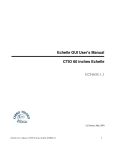
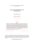
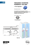
Administrator's Manual Software Architecture CTIO 60 inches Echelle ECH60S2.2 La Serena, May 2010 Echelle Administrator's Manual / CTIO 60 inches Echelle ECH60S2.2 1 Contents Introduction.....................................................................................................................................................4 Chapter 1: Software general architecture........................................................................................................5 Introduction................................................................................................................................................5 1.1 COMMSDEV (Communications Device): SYNCDEV.......................................................................7 1.1.1 Description....................................................................................................................................7 1.1.2 Configuration file..........................................................................................................................7 1.2 GUIDEV (Graphic Unit Interface Device): OPTGUI.........................................................................8 1.2.1 Description....................................................................................................................................8 1.2.2 Configuration file.........................................................................................................................8 1.3 LAMPDEV (Comparison Lamps Device): ECHLAMPDEV............................................................10 1.3.1 Description..................................................................................................................................10 1.3.2 Configuration file........................................................................................................................11 1.3.3 Header Information.....................................................................................................................13 1.3.4 Available commands...................................................................................................................13 1.4 TCSDEV (Telescope Control System Device): TCSCT60DEV........................................................15 1.4.1 Description..................................................................................................................................15 1.4.2 Configuration file........................................................................................................................15 1.4.3 Header Information.....................................................................................................................16 1.4.4 Available commands...................................................................................................................16 1.5 Data Handling System Device: DHSDEV.........................................................................................19 1.5.1 Description..................................................................................................................................19 1.5.2 Configuration file........................................................................................................................19 1.6 PAN Device: PANDEV......................................................................................................................20 1.6.1 Description..................................................................................................................................20 1.6.2 Configuration file.......................................................................................................................20 1.6.3 Available commands...................................................................................................................21 1.7 ENV (core)..........................................................................................................................................22 1.7.1 Description..................................................................................................................................22 1.7.2 Configuration file........................................................................................................................22 1.8 Iodine Cell Device: IODCELLDEV..................................................................................................24 1.8.1 Description..................................................................................................................................24 1.8.2 Configuration file.......................................................................................................................24 1.8.3 Header Information.....................................................................................................................25 1.8.4 Available Commands..................................................................................................................25 Chapter 2: Software Tree / directories..........................................................................................................27 2.1 Software tree.......................................................................................................................................27 2.2 Directories description.......................................................................................................................27 Echelle Administrator's Manual / CTIO 60 inches Echelle ECH60S2.2 2 References......................................................................................................................................................30 Glossary.........................................................................................................................................................31 Echelle Administrator's Manual / CTIO 60 inches Echelle ECH60S2.2 3 Introduction The following document is a reference to the CTIO 60 inches ECHELLE Software structure. It provides a way of understanding its' internal structure and configuration This document describes each of the devices present in this application. It also describes the directories structure and where to find binaries and configuration files. This document does not include information on how to handle the GUI (see ECH60S1.0) or commands/scripting (see ECH60S3.0), but just a basic guide to maintenance and a general view of the architecture. Echelle Administrator's Manual / CTIO 60 inches Echelle ECH60S2.2 4 Chapter 1: Software general architecture Introduction The Echelle 60 inches software is based on software modules, called “devices”, that talk to each other using a protocol called “SML”. Each device is in charge of an specific task. Each device is independent on one another, being the SML protocol the only way of “contact” between them. In this way, the software is totally modular. The “core” of the software (called “ENV”) only starts the devices at boot time Figure 1.1: software diagram In Figure 1.1 is shown a general diagram of the software. Each device is represented as a box. The SML protocol is represented as the upper black line that connects all the boxes (devices). Each device was designed for handling a very specific part of the hardware or functionality. The name of each box self explains the purpose of each device. The “external” clients can talk to the software using raw tcp/ip, Echelle Administrator's Manual / CTIO 60 inches Echelle ECH60S2.2 5 allowing easy access to scripts. The software also provides wrappers that encapsulates the tcp/ip, making even easier for the scripts or external clients to access all the functionality. Details on this wrappers is provided in Chapter 2, and details on scripting is provided in document in ECH60S3.0 (scripting). In the following points we will briefly explain each device. Panview is the application in charge of handling the camera itself (detector controller, temperatures, logs, etc). It is also the application that is generating the final fits file image (getting data from the detector controller and header information from eah of the devices). Panview can be considered a separate application, and it is explained in document ECH60S6.X Echelle Administrator's Manual / CTIO 60 inches Echelle ECH60S2.2 6 1.1 COMMSDEV (Communications Device): SYNCDEV 1.1.1 Description This device's only function is to provide an interface between the “external world” and the SML “bus” (so, the devices themselves). This device has a multiple clients tcp/ip server that allow to receive command and send responses, and also to send asynchronous messages. In general, the communications protocol is based on two channels: a command/response channel, and an asynchronous messages channel. This device, then, receives the command through the tcp/ip channel, and passes that command using SML to the appropriate device, passing then the response back from the device (SML) to the client (tcp/ip). It also passes an SML “async” message into a tcp/ip async. Channel. TCP/IP SYNCDEV SML Figure 1.2: communications device: syncdev The wrappers provided to easy scripting “hide” all this, giving to the user a single point to handle the software without the need to worry about the protocol details, other than the command and response syntax. See next chapter for examples. 1.1.2 Configuration file The configuration file is called DEV_SYNC.cfg and it is located in the standard application's configuration directory (see next chapter) [COMMS] port=1920 asyncport=1930 blockport=1940 maxcmdsvr=2 maxasyncsvr=2 // tcp multiclient command/response service port // tcp multiclient async. Server port // tcp single client blocked port // maximum amount of command/response clients allowed at a time // maximum amount of async. Client allowed at a time [LOG] log=yes // enable logging? file=__LOGPATH/DEV_SYNC.log // file log path. See next chpater for “__LOGPATH” definition Echelle Administrator's Manual / CTIO 60 inches Echelle ECH60S2.2 7 1.2 GUIDEV (Graphic Unit Interface Device): OPTGUI 1.2.1 Description The Graphic Interface itself is the front end of a SML device (a piece of software that is based in the SML protocol/structure). When the user press buttons or type controls, those actions are internally translated into an SML commands (which are, actually, ASCII commands plus some headers) that go to the devices appropriate for the actions requested. The GUI description is outside of the scope of this document. For that description, please see document ECH60S1.0 (Echelle GUI User's Manual) 1.2.2 Configuration file The configuration file is called DEV_OPTGUI.cfg (located on the standard application's configuration directory) [MISC] autopis="" beep=TRUE inforate=3000 //PlugIns to start automatically //beep when observation is done //rate to display telescope information,in msecs [LOG] log=true asyncfile=__LOGPATH/DEV_OPTGUI_async.log //log? //log file path All the entries starting as “TYPE_XXX” means: this is an observation of type XXX. Automatically the GUI will create the appropriate entries in the GUI (observation type drop down menu, controls, etc) [TYPE_Object] exptime=4.000000 nimages=1 comment=none title=none //type “Object” //last typed exposure time, in secs //last typed number of images //last typed comment //last types image title [TYPE_Dark] //type “Dark” (shutter will not open) ... [TYPE_Bias] //type “Bias” (exposure time will be always zero ... Echelle Administrator's Manual / CTIO 60 inches Echelle ECH60S2.2 8 [TYPE_Calibration] //type “calibration” (same as “flat”, selected comparison lamps will be turned ON ... Any other (arbitrary) observation type can be added here. Echelle Administrator's Manual / CTIO 60 inches Echelle ECH60S2.2 9 1.3 LAMPDEV (Comparison Lamps Device): ECHLAMPDEV 1.3.1 Description This device is in charge of handling the comparison lamps. It knows how to talk to the ADAM module in the comparison lamps control box (for details on this hardware implementation, please refer to document ECH60HF5.0) When the user requests to turn on/off an specific comparison lamp, this device receives a request, and transforms that request into a command that the hardware in the comparison lamps control box understands. Particularly, it gets translated into an ADAM's 6050 ASCII UDP command This device implements a set of interlocks to avoid undesired conditions, as having two lamps ON at the same time. As the control box also has “manual” inputs (physical switches in the console), this device also monitors those inputs (also from the ADAM module). In the following description we will call the physical switch “manual switch”, and the on/off software command “software switch”. The implemented logic follows the following rules: a) If a manual switch is detected (digital input), it turns immediately OFF all the software switches. Since the lamp control signal is an OR between the manual and the software switch, this ensures that only the lamp commanded with the manual switch will be ON. Figure 1.3 a) represent this interlock b) If the user commands, through a software switch, to turn ON a lamp while a manual switch is active, it will receive an error with an explanatory message (“manual switch is on”) c) If the user commands, through a software switch, to turn ON a lamp, while another software switch is active (not a manual switch), it will turn OFF that lamp, and after that it will turn ON the new commanded lamp. Figure 1.3 b) represents this interlock. The forced signal output “0” when another software command arrives causes the original (old) software command to be turned off (represented in the diagram as the switch at the input; a digital “1” opens the switch, a digital “0” closes it). To interpret the diagram correctly we need to assume that the switches only acts on “edges” (not states), this is, only when detecting a change in state. The device keeps polling the ADAM module,. Echelle Administrator's Manual / CTIO 60 inches Echelle ECH60S2.2 10 a) b) Figure 1.3 a): Manual switch interlock (manual switch always wins), b) Software switch interlock (last command always wins) The device also implements a timer for the “on” time (after the timer is expired the lamp will be turned off this, of course, through the software commands, because there is not control over the manual switches). This is only to avoid the observers leaving the lamps turned on after the observations. This time is a parameter that can be configured through the configuration file. 1.3.2 Configuration file The configuration file is called DEV_ECHLAMP.cfg, and it is located in the standard configurations directory (see next chapter on software tree). It is based on sections and key/value pairs (as most of the devices configurations) Echelle Administrator's Manual / CTIO 60 inches Echelle ECH60S2.2 11 [SETTINGS] address=139.229.12.49 port=1024 updaterate=1000 //ADAM 6050 address //ADAM 6050 UDP service port //polling time, in msecs, to ADAM module The rest of the entries describe th actual input/outputs Each section is a name [THAR] channel=0 inverse=false timeout=5000 type=output maxtimeon=300 // THAR lamp // ADAM output channel // implements inverted logic? // timeout, in msecs, for ON/OFF commands // ADAM signal type. “output” means “digital output” // maximum allowed “on” time, in secs [QUARTZ] channel=2 inverse=false timeout=5000 type=output maxtimeon=300 // Quartz lamp // ADAM output channel // implements inverted logic? // timeout, in msecs, for ON/OFF commands // ADAM signal type. “output” means “digital output” // maximum allowed “on” time, in secs [SW_QUARTZ] channel=0 timeout=5000 type=input // manual switch for Quartz lamp // ADAM input channel // timeout, in msecs, for reading command // ADAM signal type. “input” means “digital input” [SW_THAR] channel=2 timeout=5000 type=input // manual switch for THAR lamp // ADAM input channel // timeout, in msecs, for reading command // ADAM signal type. “input” means “digital input” [MOTOR] // Motor signal channel=5 timeout=5000 // ADAM input channel // timeout, in msecs, for reading command type=feedback // ADAM signal type. “feedback” means It is reading back an output The defined input/output for the different lamps and manual switches must correspond to the wired ADAM signals in the comparison lamps control box. For details on this, please refer to document ECH60HF5.0 (comparison lamps automation) Echelle Administrator's Manual / CTIO 60 inches Echelle ECH60S2.2 12 1.3.3 Header Information This device will send to the Data Handling System device (DHSDEV, see 1.5) the current lamp information every time a change in state is detected (read) in the ADAM module. The header information is 1 line that says COMPLAMP = ' <lamp_name>' / comparison lamp where <lamp_name> name is the name of the lamp which is ON. If no lamp is ON, “none” will appear. 1.3.4 Available commands <> indicates an obligatory field [] indicates an optional field | separates argument options Commands are case sensitive. Prefix: ECHLAMP | LAMP | LAMPS set <lamp_name> < ON | OFF> description turns on/off the specified lamp return value DONE or ERROR <error message> get <lamp_name> description gets the state of the specified lamp return value DONE or ERROR <error message> list [params] description Lists the available lamps, one line per lamps (\n separated) params: returns additional information for each lamp return value On success: Echelle Administrator's Manual / CTIO 60 inches Echelle ECH60S2.2 13 name= <lamp_name> [, channel=<channel_number>, inverse=TRUE | FALSE, timeout=<command_timeout>, type=<lamp_type>, status=TRUE | FALSE] \n ... On error: ERROR <error_message> status description brings information on the device and lamps return value On success: <lamp_name> <ON | OFF> <ON | ERROR <message>>\n ... On error: ERROR <error_message> Echelle Administrator's Manual / CTIO 60 inches Echelle ECH60S2.2 14 1.4 TCSDEV (Telescope Control System Device): TCSCT60DEV 1.4.1 Description The TCS device has in charge the communication / handling of the Telescope Control System (TCS). It can talk to the TCS computer using a serial line or the RPC protocol. Every time a new image will be taken detected as an asynchronous message from the PAN device (see 1.6), this device requests information from the TCS (usually “info” command, but this is customizable, see the configuration file description next), and that information gets passed to the Data Handling System Device (see 1.5). It also keeps polling for info, so when the connection is lost it sends an asynchronous message that the GUI device detects, turning the TCS led red (when the connection is reacquired the inverse happens, and the GUI TCS led gets turned green) 1.4.2 Configuration file The configuration file is called DEV_TCS.cfg, and is located in the standard config directory of the application. [Comms] params="type rpc_tcs, address 139.229.12.8" #params="type serial, port 0, brate 9600" tcsport=1 retries=2 //protocol type (rpc_tcs or serial), tcs address //commented out, in case serial is used // TCS service port // retries if failure [Status] updaterate(ms)=2000 postasync=false // polling rate to TCS, in msecs // generate an async. Message with the info [MISC] commands="" // commands at startup [HDRINFO] infofile=TCSCT60_INFO.tpl infocmd="POINTING, INFO, DOME" //info file template (see below) //command to send for “info”. [LOG] log=true file=__LOGPATH/DEV_TCSCT60.log // generate a log file? //log file location Echelle Administrator's Manual / CTIO 60 inches Echelle ECH60S2.2 15 1.4.3 Header Information The information that this device exports is taken from a file template. This file template states what information to export from the returned TCS information (returned from the “infocmd” stated in the configuration file. The template is specified in the key “infofile” in the configuration file The template is a sequence of lines, where each line is KEYNAME = '[(<datatype>)] <value> ' / comment\n where <value> is the value to assign to that key. The <value> can be a constant or a value from the telescope information, as returned from the “info” device command. <datatype> can be any supported datatype (FLOAT, I32, U32, I16, U16, I8, U8, STR). If no <datatype> is specified, it is assumed STR The template is: OBSERVAT='CTIO ' /Origin of data TELESCOP='CTIO 1.5 meter telescope ' /Specific system DATEOBS ='dateobs ' /date of observation start UT ='universal_time ' /UT of TCS coords RA ='ra ' /ra DEC ='dec ' /dec EPOCH ='(FLOAT) epoch ' /epoch ALT ='dome_azimuth ' /altitud HA ='hour_angle ' /ha ST ='sidereal_time ' /sidereal time ZD ='zenith_distance ' /zenith distance AIRMASS ='airmass ' /airmass For example, the field RA = 'ra' ... means that it will take whatever value the filed “ra=” has in the returning information (response to command “info”. See available commands next). The result of replacing the stated values is sent to the DHS device 1.4.4 Available commands <> indicates an obligatory field [] indocates an optional field | separates argument options Commands are case sensitive. Echelle Administrator's Manual / CTIO 60 inches Echelle ECH60S2.2 16 Prefix: TCS | TCSCT60 INFO description return current telescope information. At the low level, it sends to the TCS the commands stated under “infocmd” in the configuration file, and concatenate the responses,presenting them as stated below return value On success: Return the telescope information date= 20091223 universal_time= 17:00:34.0 dateobs= 20091223T17:00:34.0 ra= 12:45:28 dec= 64'36'' epoch= 2000.0 hour_angle= 00:30:16.1 sidereal_time= 05:04:01.1 dome_azimuth= 260.0 airmass= 1.015 zenith_distance= 12.5 slew_ra= 45.000 slew_dec= 45.000 raw_ra= 12:45:28 raw_dec= 64'36'' sidereal_time= 05:04:01.1 raw_ra= 12:45:28 raw_dec= 64'36'' apparent_ra= 12:45:28 apparent_dec= 64'36'' On error: ERROR <error_message> OFFSET <RA> <DEC> description moves the telescope (offsets) by the specified amount of arcsecs in RA and DEC response On success: OK <time> as immediate response, where <time> is the estimated time for the action, in msecs DONE (TCS:OFFSET) as callback response On error: ERROR <error message> Echelle Administrator's Manual / CTIO 60 inches Echelle ECH60S2.2 17 The TCS devices also passes to the TCS itself any other command it receives; this means that any command available in the TCS documentation can be passed straight, and the direct response will be passed back as response (see the 60 inches TCS commands reference) Echelle Administrator's Manual / CTIO 60 inches Echelle ECH60S2.2 18 1.5 Data Handling System Device: DHSDEV 1.5.1 Description This device is in charge of collecting the data that will be available for the headers and in some cases also the pixel data. The other devices will send (write) to it any information to share, and it is this device's responsibility to handle the data so the data becomes available. This particular DHS implementation connects to the “real dhs” that runs on a separate application (panview, see PAN device in 1.6) and sends any data that was written to him by the other devices. The “dhs” in panview will then write that data to the fits image headers (see diagram of Figure 1.1, where this connection between DHSDEV and panview is shown 1.5.2 Configuration file The configuration file is called DEV_DHS.cfg, and is located in the standard configuration file of the application. [DHS] params=type tcp, address localhost, port 4065, retries 6 //states how to connect to the dhs in panview: connection type (“type”), tcp address (“address”), connection port (“port”) and number of retries in failure (“retries”) Echelle Administrator's Manual / CTIO 60 inches Echelle ECH60S2.2 19 1.6 PAN Device: PANDEV 1.6.1 Description This device is in charge of handling the pixel generation and all the hardware associated to it. PAN stands for Pixel Acquisition Node, A PAN is, then, a single point of pixels / headers collections. This device is designed to handle any arbitrary amount of “PANs”, each “PAN” being in charge of some particular subsystem or detector controller. This, of course, in systems where more than one detector controller is used. In the case of this application there is only one detector controller, so this device handles a single PAN here. “Panview” is a separate program that is in charge of handling the detector controller and the camera. It is its responsibility to talk to the controller and generate the pixels and headers (data) for a single controller so, panview is a specific implementation of a PAN concept. In this application, then, the single PAN that PANDEV handles is a single panview (a single panview that handles a monsoon orange controller). PANDEV connects to panview and any request it receives regarding the controller /detector is passed directly to panview,, which is the one that actually processes the command and returns the response. PANDEV will pass back to the caller (other device) the response. The async. Messages that PANDEV receives from panview are also passed back (available to the other devices) . When there are several panviews, PANDEV is in charge of broadcasting the commands, mixing the data, etc (managing all the panviews together) ; however, in this application, having a single panview, PANDEV appears more like an interface between panview and SML 1.6.2 Configuration file The configuration file is called DEV_PAN.cfg and it is located in the standard application's configuration directory. [_echelle] // name of the panview to connect startscript=xgterm e start_panechelle // script to call at startup, to start panview stopscript=yes // when shutdown, shutdown also panview type=tcp // type of connection to panview cmdparams=address localhost, port 5415, retries 6, altport 5615 // command/response parameters asyncparams=address localhost, port 5435, retries 16, altport 5635 // asynchronous channel parameters All the configuration related to the detector specific information (readmodes, size, geometry, etc) is Echelle Administrator's Manual / CTIO 60 inches Echelle ECH60S2.2 20 handled by panview and it is not part of PANDEV. In other words, it is panview's business how to handle the controller/detector. For information and details on panview's configuration files for this application, please refer to document ECH60S6.0 (panview configuration) 1.6.3 Available commands As the commands are passed to panview, the available commands are all the available panview commands. We will not give a complete list of the available panview commands here (beyond the scope, too many of them). For that refer to document ECH60S3.X on scripting. There is presented a list of the most useful observerlevel commands Echelle Administrator's Manual / CTIO 60 inches Echelle ECH60S2.2 21 1.7 ENV (core) 1.7.1 Description ENV is the core of the application. It does not maps to any specific hardware or functionality, but defines what devices will be available and started at software startup time. It also provides a way of talking to all the devices at a time, as for broadcasting a system command (Offline/shutdown, etc. See documentation on SML devices). 1.7.2 Configuration file The configuration file is where the standard directory for configurations is. This directory is actually defined here. The configuration file is called ENV.cfg, and can be considered the first, or master configuration file [APP] name=ECHELLE // defines application name path=../ArcVIEW/ // define path to application (sources) root [ENVIRONMENT] MainVisible=False // show main window? [TRANSLATIONS] APP=PAN // defines translations, or “aliases” to the devices. See below for more details dhe="PAN DHE" // if arrives a command that start with “dhe” assumes it is PAN DHE DHE="PAN DHE" // etc FITS="PAN FITS" fits="PAN FITS" DISPLAY="PAN DISPLAY" GRTD="PAN DISPLAY" TPNT="PAN TPNT" LAMP=ECHLAMP //if a command “LAMP” arrives, send it to ECHLAMP device LAMPS=ECHLAMP pan=PAN tcs=TCS [VARS] // This defines some “global” variables, that any module can see __MODPATH=__APPPATH/modules //where the modules (devices) are __CONFPATH=./ // where the configuration directory is. __LOGPATH=../log // where the log directory is. [DEVICES] // defines where the devices are file=ENV_DEVICES.cfg // or the file where the available devices is defined. Note that here is defined the configuration directory as “./”, which means “this directory”. This means Echelle Administrator's Manual / CTIO 60 inches Echelle ECH60S2.2 22 that where this directory is, all the config files for the other modules will also be. Note also that here it is defined the global variable “__LOGPATH” that all the devices are using to define their log directory. The “translations” entry defines other names that the device can have, meaning that if a command with those names arrives it will be routed to the defined device. The file that defines what devices are available is here set as ENV_DEVICES.cfg (which is the same as ./ENV_DEVICES.cfg in the current directory In this file each section defines a device. The name of the section is the device's name. [SYNC] // device name Path=__MODPATH/SYNCDEV/public/vis/SYNC_Device.vi // path to the device's main vi (API) Commands="START; INIT" //commands to pass at load time [COMSTCP] Path=__MODPATH/COMSTCPDEV/public/vis/COMSTCP_Device.vi Commands="START; INIT" [PAN] Path=__MODPATH/PANDEV/public/vis/PAN_Device.vi Commands="START; INIT" [DHS] Path=__MODPATH/DHSDEV/public/vis/DHS_Device.vi Commands="START; INIT" [LOG] Path=__MODPATH/LOGDEV/public/vis/LOG_Device.vi Commands="START; INIT" [TCS] Path=__MODPATH/TCSCT60DEV/public/vis/TCSCT60_Device.vi Commands="START; INIT" [ECHLAMP] Path=__MODPATH/ECHLAMPDEV/public/vis/ECHLAMP_Device.vi Commands="START; INIT" [TEMP] Path=__MODPATH/TEMPDEV/public/vis/TEMP_Device.vi Commands="START; INIT" [OPTGUI] Path=__MODPATH/GUI/OPTGUI/public/vis/OPTGUI_Device.vi Commands="START; INIT" Note that __MODPATH was defined in ENV.cfg. The command “START” means “load the device”. The command “INIT” means “initialize” it. What each device does on initialization depends on the device. Echelle Administrator's Manual / CTIO 60 inches Echelle ECH60S2.2 23 1.8 Iodine Cell Device: IODCELLDEV 1.8.1 Description The Iodine Cell device is the software component that takes care of handling the ADAM module that handles the iodine cell motor (in/out). This device talks to the ADAM 6050 located on the RTD/Data IO box (see document ECH60HF7.X). It basically polls for the status of the module, and request changing the status (true/false) of the output that goes to the motor driver. The configuration file 1.8.2 Configuration file The configuration file is called DEV_IODCELL.cfg, and it is located in the standard configurations directory (see next chapter on software tree). It is based on sections and key/value pairs (as most of the devices configurations) This file describes what inputs and outputs of the ADAM will be used, and also the address/port of the ADAM module [SETTINGS] address=139.229.12.32 port=1024 updaterate=2000 Specifies the ethernet address and udp service port of the ADAM module. The updaterate specifies the polling rate in msecs [IODINE] channel=0 inverse=false timeout=5000 type=output movetime=3000 park=last Specifies the name (IODINE) and the ADAM module output (type=output) channel to use (channel=0).This means that this is set to be DO0 (Digital Output 0). It also states that the output will not be inverted (0/1 polarity), the timout for the command to be 5 seconds (timeout=5000) and the estimated time for the motor to reach its final position to be 3 secs (movetime=3000). Important, there is no Echelle Administrator's Manual / CTIO 60 inches Echelle ECH60S2.2 24 encoder or home switch, which means that the software sends the “move” commandand waits the specified time (movetime), assuming that after that the motor is in position. If the motor get stucked, or gets disengaged from the actual mechanical arm, the software will not know. [SW_IODINE] channel=0 timeout=5000 type=input Specifies the location of the manual swicth in the front panel to be Digital Input 0 (DI0)(type=input, channel=0), and the timoue 5 secs (timeout=5000). Note that internally the ADAM module does an OR between the Digital Output 0 (DO0) and the Digital Input 0 (DI0) and place the result to Digital Output 1 (DI1). This is the actual control signal applied to the motor driver 1.8.3 Header Information This device will send to the Data Handling System device (DHSDEV, see 1.5) the current iodine cell position information every time a change in state is detected (read) in the ADAM module. The header information is 1 line that says IODCELL = ' <IN | OUT>' / iodine cell position where IN means “inside light path” and OUT means “out of light path” 1.8.4 Available Commands <> indicates an obligatory field [] indicates an optional field | separates argument options Commands are case sensitive. Prefix: IODCELL | CELL set IODINE < IN | OUT> description Echelle Administrator's Manual / CTIO 60 inches Echelle ECH60S2.2 25 puts the iodine cell in or out of the light path (moves the motor in or out) return value DONE or ERROR <error message> get <name> description gets the state of the specified field. <name> can be IODINE or SW_IODINE (manual switch) return value [IN | OUT] , or ERROR <error message> list [params] description Lists the available fields, one line per each one (\n separated) params: returns additional information for each field (iodine or manual switch) return value On success: name= <IODINE | SW_IODINE> [, channel=<channel_number>, timeout=<command_timeout>, type=<input | output>, status=TRUE | FALSE] \n ... On error: ERROR <error_message> status description brings information on the device and fields (iodine cell and manual switch) return value On success: <field_name> <IN | OUT> <OK | ERROR <message>>\n ... On error: ERROR <error_message> Echelle Administrator's Manual / CTIO 60 inches Echelle ECH60S2.2 26 Chapter 2: Software Tree / directories Here we will give a view of the locations of the different software components and configuration files 2.1 Software tree Figure 2.1 shows a diagram of the software tree structure Figure 2.1: Software tree ROOT directory can be anything. In the case of this application, it is the home directory of the observer's account, /home/observer/ 2.2 Directories description apps is the directory where all the applications are. If more than one instrument is in use with the same computer,here it would appear in parallel to the specific ECHELLE application > bin: location of “generic” application scripts. The most important are: Echelle Administrator's Manual / CTIO 60 inches Echelle ECH60S2.2 27 ● start_application <name>: starts the named application (“start_application ECHELLE”) ● shutdown_application <name>: shutdown any application (“shutdown_application ECHELLE”) ● ECHELLE: this is a wrapper created at boot time to talk to the ECHELLE application from a command line. See the scripting reference document (ECH60S3.0) (“ECHELLE LAMP set QUARTZ ON”) > ECHELLE: directory of specific ECHELLE application ● ArcVIEW: directory where sources are ○ modules: all devices sources, one directory per device ○ bin: generic arcview scripts (startup and shutdown, etc) ● doc: specific echelle application documentation ● log: all log files of devices (__LOGPATH) ● bin: specific echelle application scripts: ○ ○ ○ ● start_ECHELLE: starts echelle application. This is a “start_application ECHELLE” plus some process checking, polling, etc. This is the script actually used to start the application (see ECH60S1.0) shutdown_ECHELLE: shutdown echelle application. This is a “shutdown_application ECHELLE” plus some process checking, poling, etc. This is the script actually used to shutdown the application (see ECH60S1.0) sendsockcmd: binary (executable) that is used by the wrappers to talk to the application (opens a socket, sends the command, prints the response, closes the socket). config : this is the directory where all the device's configuration files are: DEV_PAN.cfg, DEV_ECHLAMP.cfg, DEV_TCSCT60.cfg, DEV_OPTGUI.cfg, ENV.cfg, etc In general, the user (observer) should not edit any of this. The administrator (maintenance) should be aware mostly of the configuration directory (apps/ECHELLE/config) and the specific echelle binaries (apps/ECHELLE/bin) The wrapper ECHELLE, in apps/bin, provides an easy way of interacting with the application using simple command line (and hence, scripting). This is a simple csh built at boot time, that calls the binary “sendsockcmd” to open the communications channel (socket) and get the response. Example: Echelle Administrator's Manual / CTIO 60 inches Echelle ECH60S2.2 28 ECHELLE LAMP QUARTZ ON Will open a socket to the application, send the command “LAMP QUARTZ ON”, wait for the response and print it. In this way, using this as part of a bigger script is very easy. All the details in can be found on the scripting reference document ECH60S3.0 Echelle Administrator's Manual / CTIO 60 inches Echelle ECH60S2.2 29 References ● SML documentation ● TCS 60 inches documentation / command list Echelle Administrator's Manual / CTIO 60 inches Echelle ECH60S2.2 30 Glossary Device: A software component that encapsulates a specific functionality. It must have a very standard and well defined internal structured and inputs/outputs, so they can be “pluged” into any application that uses devices SML: A communications protocol used by the devices to talk to each other. This is a simple protocol that sends ASCII commands and headers. The protocol makes it transparent if the application's devices are in the same machine or distributed among several ones. Echelle Administrator's Manual / CTIO 60 inches Echelle ECH60S2.2 31