1
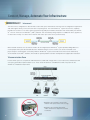
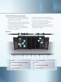
PANVIEW iQ™ PHYSICAL INFRASTRUCTURE MANAGEMENT SYSTEM
Enabling Intelligence Throughout the Physical Layer
The Case for Network Intelligence
In today’s data center, the quick identification and resolution of network problems and security threats is key to
business success. However, many organizations overlook the importance of deploying network intelligence in
the data center.
Without real-time monitoring and visibility into dense physical layer connectivity, enabled by an intelligent
physical infrastructure management system, enterprises are vulnerable to risk across several areas:
Security and Regulatory Compliance
• Disruptions caused by inadvertent disconnections or potential security breaches may not be
identified in sufficient time for proper remedial response
• Without systems in place to ensure financial information and corporate communications are
adequately protected, enterprises may find themselves in violation of industry regulations
(from Sarbanes-Oxley, Basel II and HIPAA to Gramm-Leach-Bliley)
Network Availability
• Improperly executed patch field changes may not be easily detected in a timely manner, resulting
in substantial downtime to network services and mission-critical applications
• Manual documentation and maintenance of patch field connectivity are dependent on adherence
to written processes and manual audits which require substantial effort
Response Time
• Without a “snapshot” of their network connectivity and capacity, organizations require more time
for planning and installation
• Notification delays can prolong network downtime and hamper disaster recovery measures,
resulting in significant cost to repair and restore connectivity
Asset Utilization
• Unused or wasted server and switch ports reduce the effectiveness of data center consolidation
efforts and prolong the time required to achieve ROI on IT assets
• Lost or poorly configured hardware assets are difficult to track, which complicates
commissioning/decommissioning projects and increases labor costs associated with repair
and replacement
Physical infrastructure management systems provide automated, accurate, and up-to-date tracking of network connections
through monitoring and reporting capabilities, critical to timely infrastructure diagnosis and troubleshooting efforts.
2
Overcoming the Challenges
The PANVIEW iQ ™ Physical Infrastructure Management System helps IT stakeholders address risk by
providing real-time monitoring and visibility of physical layer connectivity within enterprise data centers and
telecommunication spaces.
Benefits of the system include:
Automated Documentation of Network
Captures planned and unplanned changes that occur in patch field connectivity and automatically
updates the connectivity database
Asset Management and Reporting
Documents and manages network inventory for increased speed of configuration and efficient
record retrieval and reporting
Work Order Management and Tracking
Guides, monitors and expedites the work order process and manages scheduled network maintenance activities
Web-Based Remote Management
Enables local and remote management accessible from anywhere in the world
Scalable Deployment Options
Allows deployment flexibility to accommodate growth as
business needs evolve
3
Enhancing Network Security
Maintaining network security has traditionally meant restricting access points and protecting the network
infrastructure from data corruption, viruses, or physical damage. However, laptop computing, remote
workforces, messaging, and peer to peer Internet applications have widened the scope of security risks.
Additionally, new industry rules, requirements, and regulations have forced organizations to rethink their
security strategies in order to improve the safe and secure transmission of sensitive data and information.
The PANVIEW iQ ™ Physical Infrastructure Management System enhances network security with effective controls
and reporting processes.
Real-Time Monitoring of Patch Field Connections
Scans patch field connections 24 hours a day/365 days a year to provide network administrators with visibility
into the physical layer to track activities locally or remotely
Unauthorized Access or Change Alerts
Provides real-time notification of unauthorized access or changes in the physical layer patch field, allowing for
quick isolation, notification, and resolution of faults or potential security breaches
Asset Tracking and Documentation
Utilizes a comprehensive, relational database to document and manage physical layer connectivity in the
network to identify, track and report all asset movements, providing auditable event logs that comply with
industry regulations
4
Improving Network Reliability
Enterprises require uninterrupted user access to mission-critical business applications. The most common service
interruptions to the physical layer result from moves, adds, and changes (MACs) that are needed to grow data
center capacity and extend the life of active equipment and connectivity. Human error related to (MACs), as well
as outdated records, have made automation a necessity to ensure optimum network availability.
The PANVIEW iQ ™ Physical Infrastructure Management System provides:
Automated Patch Field Verification and Documentation
Verifies the accuracy of the patch field database at all times and creates automated documentation to provide
real-time visibility of the physical layer, without manual record keeping
Point and Click Diagnostics
Allows visibility to the current status of patch field connectivity for improved troubleshooting and response time
Simplifies connectivity troubleshooting by allowing interaction with an on-screen infrastructure map of all
physical layer links
Guided Moves, Adds, and Changes
Documents MACs for planned configuration changes and provides a defined set of IT staff instructions,
reducing risk of errors and improving speed of deployment
Web-Based Management
Utilizes a graphical user interface (GUI) that provides intuitive, easy to use network manageability
Remote Accessibility
Allows global network access via a web-browser for cost-effective network management and access
to vital network information from anywhere in the world
5
Connect, Manage, Automate Your Infrastructure
Interconnect
The interconnect configuration is ideal for data centers with space limited areas that have lower reconfiguration requirements
and utilize higher density connections than other computing areas. The new PANVIEW iQ ™ System interconnect capability
provides the assurance of accurate switch port provisioning and patch field documentation when monitored by the PANVIEW
iQ ™ PHYSICAL INFRASTRUCTURE MANAGER ™ (PIM ™) Software. This revolutionary design requires no additional cables, appliances,
or obstructive overlays on a switch which interfere with switch port connections (see box below).
When network elements such as switches need to be reconfigured, the PANVIEW iQ ™ System provides LED guidance to
ensure proper switch port allocation/de-allocation. Network elements such as servers can also be monitored at the
physical layer to ensure proper connectivity. With the PANVIEW iQ ™ System, both ends of the switch-server relationship
are monitored via the PIM ™ Software, which leads to quicker problem resolution and rapid service/application restoration.
Telecommunications Room
In areas where space is at a premium and limited moves, adds and changes will occur, an interconnect infrastructure will
save space and reduce implementation costs. These areas will utilize the unmodified local switch to patch into the
PANVIEW iQ ™ Distribution Patch Panel.
• Eliminates the need for scanner units
and the rack spaces these units occupy
• Eliminates the need for attachment
cables and stick-on strips which mount
to switches
6
Interconnect and cross-connect are both proven methods of connecting network elements within data centers
and telecommunication rooms. The density of IT assets within racks and cabinets as well as the frequency of
asset reconfigurations will drive the decision on which method will be most effective.
PANVIEW iQ ™ (PViQ ™ ) Interconnect Benefits
• Unique PViQ ™ Provisioning Port and Intelligent
Interconnect Patch Cords guide installers to the
correct switch and panel ports for flawless MACs
• Monitors all server (or other networking devices)
connections and disconnections connected to PViQ ™
Patch Panels with PViQ ™ Interconnect Patch Cords
• Detects connections and disconnections made
between the switch and PViQ ™ Patch Panels and
visually identifies these ports through colored LEDs
on the PViQ ™ Patch Panels, as well as LEDs built
into enhanced PViQ ™ Interconnect Patch Cords
• Reports and provides asset tracking of devices with
the PViQ ™ PIM ™ Software through on-screen, email
or network (SNMP) notification
• PViQ ™ PHYSICAL INFRASTRUCTURE MANAGER ™ (PIM ™)
Application Software is notified in the event of
completed patching or connection violations
• Lowers operational and administrative costs and
establishes higher physical layer security allowing
for faster response times
Data Center
5
3
3
2
2
4
1
1
Switches
4
Servers
2
PANVIEW iQ ™ Interconnect Patch Cords
5
Horizontal Cabling
3
PANVIEW iQ ™ Patch Panels
7
Connect, Manage, Automate Your Infrastructure
Cross-Connect
A cross-connect infrastructure is warranted in data centers where server commissioning/decommissioning and equipment
cut-overs necessitate configuration flexibility and cable routing for application reconfigurations.
In cross-connect configurations, the more permanent and highest density network element (such as the high-speed switch)
is permanently cabled through the back of a PANVIEW iQ ™ Intelligent Patch Panel with modular jacks. Patch cords are then
connected between the representative switch-port panel and the remote routable PANVIEW iQ ™ Patch Panel cabled via
horizontal runs to remote cabinets typically containing other network elements (e.g., servers) or endpoint equipment (e.g.,
computers, IP phones, security equipment, etc.).
Telecommunications Room
Intermediate distribution areas or data-communications closets (as shown below), may implement a cross-connect
infrastructure to reduce the facility reconfiguration costs and cabling time.
8
PANVIEW iQ ™ (PViQ ™ ) Cross-Connect Benefits
• Provides a high level of physical security and asset
tracking of devices with the PViQ ™ System from the
logical layer to the physical layer
• PViQ ™ Patch Panels detect double-ended (both ends
connected) and single-ended (far end disconnected)
connections for improved fault isolation
• The PViQ ™ PIM ™ Application can automatically
commit cross-connect patch field configurations on
selected panels to database
• Guides moves, adds, and changes (MACs) from
either patch panel in the cross-connect configuration
• Extends port visibility and accessibility of
expensive, mission-critical switching equipment
into an easily reconfigurable patch field
• Maps other network elements such as servers and
storage devices through representative panel ports
and PViQ ™ PIM ™ Software
Data Center
8
7
5
4
3
1
6
2
3
1
Switches
5
Standard Patch Panels
2
PANVIEW iQ ™ Cross-Connect Patch Cords
6
Servers
3
PANVIEW iQ ™ Patch Panels
7
Standard Plug-to-Jack Cabling
4
Standard Patch Cords
8
Horizontal Cabling
9
PANVIEW iQ ™ Intelligent Module:
Panel Manager or
Expansion Module
PANVIEW iQ ™
Patch Panel
Mounting
Bracket
System Overview
MINI-COM ®
Jack Module
PANVIEW iQ ™
Interface Unit
The unique flexible design of the PANVIEW iQ ™ System uses intelligent modules that
snap directly into the back of PANVIEW iQ ™ Patch Panels, eliminating the need for additional
PANVIEW iQ ™
Patch Cord
hardware components that consume valuable rack space.
PANVIEW iQ ™ Patch Panels
PANVIEW iQ ™ Patch Panels have been developed with functionality, scalability, and consideration for rack space
efficiency. The innovative patch panel design provides opportunities for phased installations that allow an
organization to install passive connectivity now and upgrade to a fully managed system at a later time.
The PANVIEW iQ ™ Patch Panels which include flat (UTP and STP) and angled (UTP and STP) styles provide
flexibility by offering compatibility with all MINI-COM ® offering UTP, and STP Copper Modules, as well as LC
Fiber Optic Adapters.
PANVIEW iQ ™ Interface Units
The revolutionary interface unit eliminates the need for separate control equipment by allowing the following
operational modes to be accessed or viewed directly from the front of the panel:
• Visually and audibly alert user when any changes are made – Secure Mode
• Notify user when pending change order has been sent to the PViQ™ Patch Panel – MAC Mode
• Direct user to near and far end of patch field for end-to-end connectivity verification – Trace Mode
• Diagnostic services available locally and remotely – Maintenance Mode
• Commit current patch field configuration on selected panels to database – Learn Mode
The provisioning port allows guided patching from PANVIEW iQ ™ Panels to designated switch ports in support of
secure network segmentation.
Indicator LEDs
Navigation
Buttons
Provisioning
Port
Interface unit shown for PANVIEW iQ ™ Panel Manager (PM).
Interface unit for PANVIEW iQ ™ Expansion Manager (EM)
does not contain provisioning port.
10
PANVIEW iQ ™ Intelligent Modules
Panel Manager (PM)
Expansion Module (EM)
The PANVIEW iQ Panel Manager is designed to
consolidate patch field scanning and management
functions into a single, removable module. It
contains an embedded web interface for remote
management and access to connectivity information.
The PANVIEW iQ ™ Expansion Module cost-effectively
expands the scanning and management capabilities
of the PANVIEW iQ ™ Panel Manager to additional
patch panels.
™
Panel Manager
(PM) Connections
Expansion Module
(EM) Connections
MAC
Address Label
Expansion Port
for EM
LAN Connectors for
Daisy Chaining PMs
12V Power
Input
In and Out Expansion Ports
PHYSICAL INFRASTRUCTURE MANAGER ™ (PIM ™) Software
PANDUIT ® PHYSICAL INFRASTRUCTURE MANAGER ™ (PIM ™) Software is a web-based application suite that
maps and monitors both the physical layer and network resources to enable better infrastructure visibility
and to reduce network operational cost.
The application suite provides automated network documentation and maintenance for the physical layer,
offering improved reliability and security while increasing overall network management efficiency.
11
Innovative PANVIEW iQ ™ Enhanced Interconnect Patch Cords
The interconnect patching capability of the PANVIEW iQ ™ Physical Infrastructure Management System allows for
accurate connections and disconnections between PANVIEW iQ ™ Patch Panels and specified switch ports
through visual verification of change orders as defined through the PANVIEW iQ ™ PHYSICAL INFRASTRUCTURE
MANAGER ™ (PIM ™) Software.
The higher density of connection points on network equipment creates risk when changes are required.
Identification of proper switch ports is imperative to ensure business continuity so that applications and
services are not improperly connected or mistakenly taken out of service. The speed and accuracy of
connecting to the correct switch port is increased through guided visual notification.
Building upon the functionality of the basic PANVIEW iQ ™ Interconnect Patch Cords (shown on page 17), the
new enhanced PANVIEW iQ ™ Interconnect Patch Cords (shown illustrated below) implement an industry-first
design which integrates LEDs directly into the patch cord plug, providing visual verification of accurate
patching and tracing activities.
• Accurate Network Switch Port Connections
Enhanced PANVIEW iQ ™ Interconnect Patch Cords visually indicate and verify
accurate insertion at the switch port, ensuring that the right services and
networking capabilities are provided for this connection.
• Guided Disconnects
The PANVIEW iQ ™ System guides removal of interconnect patch cords from both
the switch and corresponding patch panel to reduce risk and enable secure
disconnects, reducing the potential for service disruption to peripheral ports.
• Visual Traceability
Enhanced PANVIEW iQ ™ Interconnect Patch Cords enable port tracing between
PANVIEW iQ ™ Patch Panels and network switches via local access or remote
management. This innovative capability allows for direct mapping and
verification of end-to-end patch field connection points.
PANVIEW iQ ™ Enhanced Cross-Connect Patch Cords
LEDs integrated into the plug end of enhanced PANVIEW iQ ™ Cross-Connect Patch Cords provide visual
verification of accurate patching and tracing activities.
• Guided Bundle Patching
Enhanced PANVIEW iQ ™ Cross-Connect Patch Cords help to identify the
appropriate patch cord when large cable bundles are being routed through
horizontal and vertical cable managers. This saves time and increases the
accuracy of the patching operation.
• Accurate Connections
Enhanced PANVIEW iQ ™ Cross-Connect Patch Cords visually indicate and verify insertions at
both ends of the connection, confirming that the patching request has been reliably completed.
12
Installation Example
Rear View of a 96-Port Connectivity Management Kit
1
2
3
5
4
1
PANVIEW iQ ™ Expansion Module (EM)
Up to 3 EMs may be connected and extended
from each PM
2
PANVIEW iQ ™ Expansion Port Cable
(included with an expansion module) that
carries power and data between all modules
3
4
RJ45 Patch Cord
(included with a PANVIEW ™ Panel Manager)
that connects the PM to additional PMs via a
LAN connection
5
Power Supply Input
for the PANVIEW iQ ™ Panel Manager (PM)
PANVIEW iQ ™ Panel Manager (PM)
Up to 50 connected PMs may be patched to
a single switch port
13
PANVIEW iQ ™ Patch Panels
PANVIEW iQ ™ Patch Panels revolutionize intelligent physical infrastructure management by providing a modular and
scalable approach to meet the demands of enterprise and data center installations. Standard copper and fiber cabling is
used for all (horizontal link) terminations onto the back of these panels while unique PANVIEW iQ ™ Patch Cords are used
for cross-connect or interconnect installations. The innovative design of PANVIEW iQ ™ Patch Panels permit cabling and data
connectivity to be installed immediately with “intelligence ready” connections that allow the incremental growth and
provisioning of panel management capabilities.
• Accommodates intelligent modules that mount in the rear
and utilize no additional rack space (zero RU)
• Accepts all MINI-COM ® UTP, STP, and LC Fiber
Optic Modules
• Accepts a PANVIEW iQ ™ Interface Unit to provide patch
cord tracing and provisioning of switch ports with PANVIEW
iQ ™ Interconnect Patch Cords or patch field mapping with
PANVIEW iQ ™ Cross-Connect Patch Cords
• Mount to standard EIA 19" rack or 23" racks with optional
extender bracket
Part Number
Part Description
No. of Std. Std.
Rack Pkg. Ctn.
Spaces^ Qty. Qty.
Angled PANVIEW iQ ™ Patch Panels
PVQ-MIQAPU24
PVQ-MIQAPU24 24-port unpopulated angled modular intelligent module
ready patch panel accepts all MINI-COM ® UTP and LC Fiber
Optic Modules.
PVQ-MIQAPS24 24-port unpopulated angled modular intelligent module
ready patch panel accepts all MINI-COM ® STP Modules.
1
1
10
1
1
10
1
1
10
1
1
10
4
1
—
Flat PANVIEW iQ ™ Patch Panels
PVQ-MIQPU24
PVQ-MIQPU24
PVQ-MIQPS24
24-port unpopulated modular intelligent module ready
patch panel accepts all MINI-COM ® UTP and LC Fiber
Optic Modules.
24-port unpopulated modular intelligent module ready patch
panel accepts all MINI-COM ® STP Modules.
PANVIEW iQ ™ Connectivity Management Kit
PVQ-MIQPS96F
PVQ-MIQPS96F For standard configurations, this 96-port modular
intelligent panel kit includes four flat PANVIEW iQ ™ Patch
Panels (PVQ-MIQPU24), one PANVIEW iQ ™ Panel Manager
with interface unit, and three PANVIEW iQ ™ Expansion
Modules with expansion port cables and interface units.
Also includes one 1.5' (0.5m) RJ45 patch cord for
connection to network switch or additional daisy-chained
PANVIEW iQ ™ Panel Managers. (Power Supply, PANVIEW iQ ™
Patch Cords and MINI-COM ® Modules are not included and
must be purchased separately.)
[PVQ-MIQPS96A will be released as an angled kit.
See website for availability at www.panduit.com/pim.]
^One rack space = 1.75" (44.45mm).
PANVIEW iQ ™ Panel Manager requires proper country specific power supply (PVQ-PS12VDC-S for North America,
PVQ-PS12VDC-E for Europe, or PVQ-PS12VDC-U for United Kingdom) which must be ordered separately.
14
PANVIEW iQ ™ Fiber Trays
Part Number
Part Description
No. of Std. Std.
Rack Pkg. Ctn.
Spaces^ Qty. Qty.
PVQ-FMT
24-port PANVIEW iQ ™ Fiber Tray with no
fiber adapters.
1
1
1
PVQ-FMTMTP-ZX
24-port PANVIEW iQ ™ Fiber Tray including 24
(CMDSAQLCZBL) LC SR./SR. 10 GIG ™ SFF duplex
multimode aqua adapters with zirconia ceramic
split sleeves.
1
1
1
PVQ-FMTMTP-9
24-port PANVIEW iQ ™ Fiber Tray including 24
(CMDSLCZBU) LC SR./SR. SFF duplex singlemode
blue adapters with zirconia ceramic split sleeves.
1
1
1
PVQ-FMT
PANVIEW iQ ™ Intelligent Modules
PANVIEW iQ ™ Intelligent Modules enable the PANVIEW iQ ™ Patch Panels to sense connections and disconnections from each
port and relay status information to the PHYSICAL INFRASTRUCTURE MANAGER ™ (PIM ™) Software Database. The intelligent
modules also accept trace mode and MAC commands to provide guidance via the PANVIEW iQ ™ Interface Unit and Patch
Panel LEDs.
• Provides manageability for a PANVIEW iQ ™ Patch Panel
• Eliminates the need for additional rack space by attaching
directly to the back of a PANVIEW iQ ™ Patch Panel
• Enables quick addition, removal, or replacement of
intelligent modules to add management capabilities
• Supports both cross-connect and interconnect installations
PVQ-PM
• The intelligent panel manager (PM) module provides
networking interface, power connection and expansion
port connections
• The intelligent expansion module (EM) receives all power
and data signals from the PM through the expansion port.
Three EMs can be connected to one PM
Part Number
Part Description
PVQ-PM
Panel manager (includes mounting bracket, 1.5' (0.5m) RJ45 patch cord, and
interface unit).
PVQ-EM
Expansion module (includes mounting bracket, expansion port cable, and
interface unit).
Std.
Pkg.
Qty.
1
1
™
PANVIEW iQ Panel Manager requires proper country specific power supply (shown on page 16) which must be
ordered separately.
PVQ-EM
15
PANVIEW iQ ™ Power Supply
• Provides 12 volts of regulated power
• One power supply required per PANVIEW iQ ™ Panel
Manager module
Part Number
PVQ-PS12VDC-S
PVQ-PS12VDC-E
PVQ-PS12VDC-U
• Offers flexible placement inside of rack
• 5 foot (1.5m) cord length
Part Description
30W power supply for North America.
30W power supply for Europe.
30W power supply for UK.
Std.
Pkg.
Qty.
1
1
1
PHYSICAL INFRASTRUCTURE MANAGER ™ Software
• Supports the PANVIEW iQ ™ System
• Provides automated documentation of network patch
field connectivity
• Provides real-time notification of all changes in physical
layer patch field
• Documents and assigns moves, adds, and changes for
planned configuration changes
• Utilizes a web-based graphical user interface that is
globally accessible
• Allows integration between third-party programs via the
PANDUIT Application Programming Interface (API) e.g.
HP OpenView Network Node Manager^
Part Number
Part Description
PIMS-MEDIA Software user manual with PHYSICAL INFRASTRUCTURE MANAGER™ (PIM ™)
SOFTWARE CD and support tools.
PIMS-100EL
PIMS-1KEL
PIMS-MA-B1
Endpoint license for 100 intelligent links.
Endpoint license for 1000 intelligent links.
Software maintenance agreement, basic, 1-year.
^HP, OpenView, and Network Node Manager are registered trademarks of Hewlett-Packard Development
Company, L.P.
16
Std.
Pkg.
Qty.
1
1
1
1
PANVIEW iQ ™ Patch Cords
• PANVIEW iQ ™ Interconnect Patch Cords support
connectivity between shielded non-PANVIEW iQ ™ enabled
ports (e.g., switches with shielded jacks, servers with
shielded jacks, etc.) and PANVIEW iQ ™ Panel Ports
Part Number
• PANVIEW iQ ™ Cross-Connect Patch Cords manage and
map the patch field between two PANVIEW iQ ™
Patch Panels
• All PANVIEW iQ ™ Patch Cords permit PANVIEW iQ ™ Panels
to detect single-ended connections
Part Description
Std. Std.
Length Cable Pkg. Ctn.
Ft. m Color Qty. Qty.
Copper Interconnect Patch Cords – Basic
PVQ-BIU6C3BU*
Category 6 UTP interconnect patch cord for
use with PANVIEW iQ ™ Patch Panel,
Communications (CM) rated.
3
—
Blue
1
10
PVQ-BIU6L1MBU^
Category 6 UTP interconnect patch cord for
use with PANVIEW iQ ™ Patch Panel, Low
Smoke Zero Halogen (LSZH) rated.
—
1
Blue
1
10
PVQ-BIU6C3BU
Additional lengths and colors available:
*For lengths of 5, 7, 10, 14 or 20 feet, change the length designation in the part number to the desired length. For
standard cable color other than BU (Blue), replace BU in the part number with GR (Green). For example, the part
number for a green, 5-foot patch cord is PVQ-BIU6C5GR.
^For lengths of 2, 3, 5 or 10 meters, change the length designation in the part number to the desired length. For
standard cable color other than BU (Blue), replace BU with WH (White). For example, the part number for a white
2 meter patch cord is PVQ-BIU6L2MWH.
Contact PANDUIT Customer Service for lead times and for non-standard lengths and colors.
Part Number
Part Description
Std. Std.
Length Cable Pkg. Ctn.
Ft. m Color Qty. Qty.
Copper Interconnect Patch Cords – Enhanced
PVQ-EU6AC3BU*
10GIG ™ UTP Enhanced Interconnect Patch
Cord for use with PANVIEW iQ ™ Patch Panel,
CM rated.
3
—
Blue
1
10
PVQ-ES6X3BU*
10GIG ™ STP Enhanced Interconnect Patch
Cord for use with PANVIEW iQ ™ Patch Panel,
dual rated.
3
—
Blue
1
10
PVQ-ES6X1MBU^
10GIG ™ STP Enhanced Interconnect Patch
Cord for use with PANVIEW iQ ™ Patch Panel,
dual rated.
—
1
Blue
1
10
Additional lengths and colors available:
*For lengths of 1, 2, 5 or 10 feet, change the length designation in the part number to the desired length. For standard cable color other than BU (Blue), replace BU in the part number with WH (White). For example, the part number for a white, 5-foot patch cord is PVQ-EU6AC5WH.
^For lengths of 2, 3, 5 or 10 meters, change the length designation in the part number to the desired length. For
standard cable color other than BU (Blue), replace BU with WH (White). For example, the part number for a white
2 meter patch cord is PVQ-ES6X2MWH.
Contact PANDUIT Customer Service for lead times and for non-standard lengths and colors.
17
PANVIEW iQ ™ Patch Cords (continued)
Part Number
Part Description
Std. Std.
Length Cable Pkg. Ctn.
Ft. m Color Qty. Qty.
Copper Cross-Connect Patch Cords – Basic
Category 6 UTP patch cord for use with
PANVIEW iQ ™ Patch Panel.
3
—
Blue
1
10
PVUTPSPC1MBBUY^ Category 6 UTP patch cord for use with
PANVIEW iQ ™ Patch Panel.
—
1
Blue
1
10
PVUTPSPC3BBUY*
PVUTPSPC*BBUY
PVSTP6X*MBBU
PVSTP6X1MBBU^^
Category 6A, STP modular 10GIG ™ Patch
Cord for use with PANVIEW iQ ™ Patch Panel.
—
1
Blue
1
10
PVUTP6X1MBBU‡
Category 6A, UTP modular 10GIG ™ Patch
Cord for use with PANVIEW iQ ™ Patch Panel.
—
1
Blue
1
10
Additional lengths and colors available:
*For lengths of 5, 7, 10, 14 or 20 feet, change the length designation in the part number to the desired length.
Available in (BU) blue only. For example, the part number for a blue 5-foot patch cord is PVUTPSPC5BBUY.
^For lengths of 2, 3, 5, 7 or 10 meters, change the length designation in the part number to the desired length. For
standard cable color other than BU (Blue), replace BU with GR (Green). For example, the part number for a green
5 meter patch cord is PVUTPSPC5MBGRY.
^^For lengths of 2, 3, 5, or 10 meters, change the length designation in the part number to the desired length. For
standard cable color other than BU (Blue), replace BU with BL (Black), RD (Red), GR (Green) or YL (Yellow). For
example, the part number for a green 5 meter patch cords is PVSTP6X5MBGR.
‡For lengths of 2, 3, 5, or 10 meters, change the length designation in the part number to the desired length. For
standard cable color other than BU (Blue), replace BU with BL (Black), RD (Red), GR (Green) or YL (Yellow). For
example, the part number for a green 5 meter patch cord is PVUTP6X5MBGR.
Contact PANDUIT Customer Service for lead times and for non-standard lengths and colors.
Copper Cross-Connect Patch Cords – Enhanced
Contact PANDUIT for availability.
18
PANVIEW iQ ™ Patch Cords (continued)
Part Number
Part Description
Std. Std.
Length Cable Pkg. Ctn.
Ft. m Color Qty. Qty.
Fiber Cross-Connect Patch Cords
PVF9L10-10M*Y
PVF9L10-10M0.5Y*
Singlemode LC-LC, Duplex 9 micron patch
cord for use with PANVIEW iQ ™ Patch Panel,
Low Smoke Zero Halogen (LSZH) rated.
—
.5 Yellow
1
10
PVFXL10-10M0.5Y^
Multimode LC-LC, Duplex 50 micron
OM3 patch cord for use with PANVIEW iQ ™
Fiber Tray, Low Smoke Zero Halogen (LSZH)
rated.
—
.5
1
10
Aqua
Additional lengths available:
*For lengths .5 meters to 10 meters (0.5 meter increments), change the length designation in the part number to
the desired length (yellow only). For example, the part number for a yellow 7.5 meter singlemode LC-LC patch
cord PVF9L10-10M7.5Y.
^For lengths .5 meters to 10 meters (0.5 meter increments), change the length designation in the part number to
the desired length (aqua only). For example, the part number of an aqua 7.5 meter multimode LC-LC patch cord is
PVFXL10-10M7.5Y.
Contact PANDUIT Customer Service for lead times and for non-standard lengths and colors.
Cable Labels for PANVIEW iQ ™ Patch Cords
Suggested Label Solutions for TIA/EIA-606-A Compliance
Patch Cord
Part Number
All Patch Cords
Laser/Ink Jet Desktop TDP43MY Thermal Transfer
PANTHER ™ LS8E
Printer Label
Desktop Printer Label
Hand-Held Printer Label
S100X150YAJ
S100X150VATY
S100X150VAC
COUGAR ™ LS9
Hand-Held Printer Label
T100X000CBC-BK
19
PANDUIT Corp.
Tinley Park, Illinois 60477-3091
For more information
Visit us at www.panduit.com
Contact Customer Service by email: [email protected]
or by phone: 800-777-3300
PANDUIT Europe Ltd.
London, UK
[email protected]
Phone: 44.20.8601.7200
PANDUIT Japan
Tokyo, Japan
[email protected]
Phone: 81.3.6863.6000
PANDUIT Singapore Pte. Ltd.
Republic of Singapore
[email protected]
Phone: 65.6305.7575
PANDUIT Latin America
Jalisco, Mexico
[email protected]
Phone: 52.333.777.6000
PANDUIT Australia Pty. Ltd.
Victoria, Australia
[email protected]
Phone: 61.3.9794.9020
PANDUIT Canada
Markham, Ontario
[email protected]
Phone: 800.777.3300
WO R L DW I D E H E A D Q UA RT E R S
© 2009 PANDUIT Corp.
ALL RIGHTS RESERVED.
Printed in the U.S.A.
Brochure Number SA-PVCB16
3/2009